|

Bartels AutoEngineer®
Product Information
Last Change
The following pictures show typical screen shots of the
Bartels AutoEngineer® software.
The basic BAE user interface is identical on the supported platforms. However, through the
User Language which is freely available with every BAE system, the features for customizing the menu layout and adding new functions virtually unlimited. We are encouraging and supporting users in adapting the menu to their special requirements. I.e., customer-specific BAE menus are commonplace...
Figure 1 shows a screen shot from the
BAE HighEnd main menu screen on
Windows XP. The
function starts additional processes coupled with the current process, thus allowing for inter-module communications such as cross-highlighting between the
Schematic Editor and the
PCB Layout Editor. The
CAM View module including Gerber viewer, panelization functions and manufacturing data optimizers is provided with every
AutoEngineer layout system at no additional cost. The menu below also shows the function for activating the optional
IC/ASIC Design system:
Figure 1: Bartels AutoEngineer HighEnd Main Menu
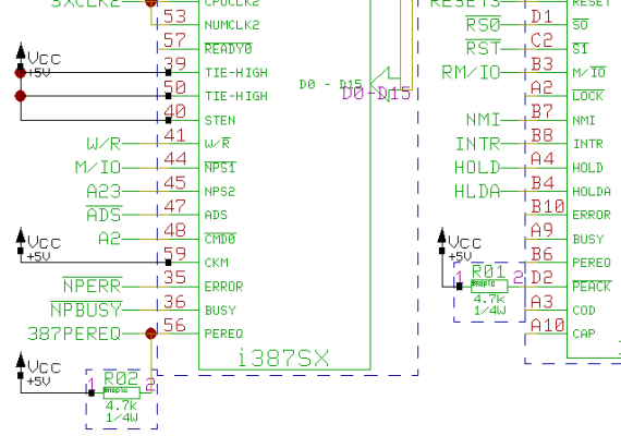
Figure 2 shows a typical
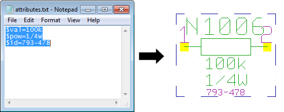
Schematic Capture session. The toolbar at the left provides buttons for frequently used display and file functions, design view management facilities, and a feature for automatic part attribute settings, all of which is designed and can be fully customized through
User Language. Please note the resistor attributes and the bus connection to the processor IC in the schematic plan. The system automatically connects the individual bus lines based on the logical library description:
Figure 2: Bartels AutoEngineer Schematic Capture
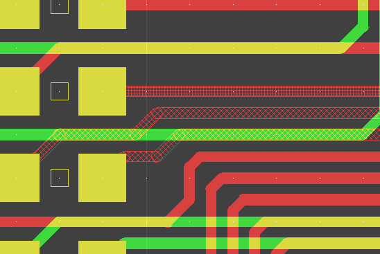
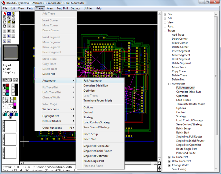
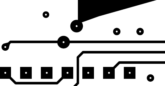
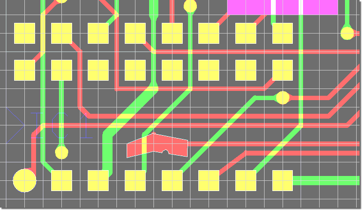
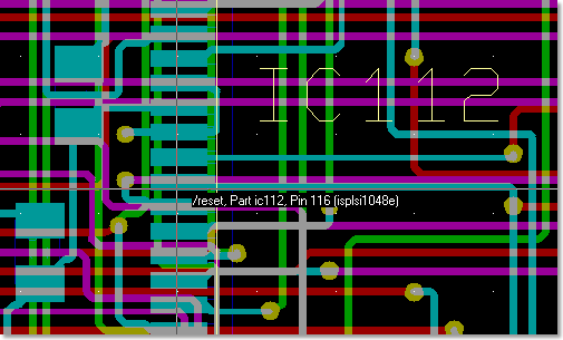
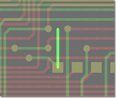
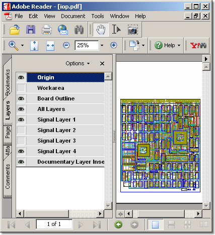
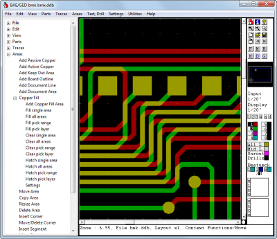
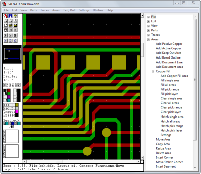
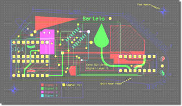
Figure 3 shows a typical
PCB Layout Editor window. The PCB layout displayed shows a mixture of possible design options, such as the use of surface mounted devices (SMDs), curved traces, negative split power planes, positive copper pour areas, irregular pad and copper shapes, etc. The DRC is able to handle all these online and in real time, as it is based on an incremental technology which also allows for multi-step
. The toolbar on the lefthand side is designed with
User Language and provides design view management facilities and buttons for frequently used display and file access functions:
Figure 3: Bartels AutoEngineer PCB Layout
An IC design module including real-time mask connectivity, GDS2 I/O, Standard Cell Placement with intelligent algorithms as well as routing using the
Bartels AutoEngineer in its IC design version is available as an option.
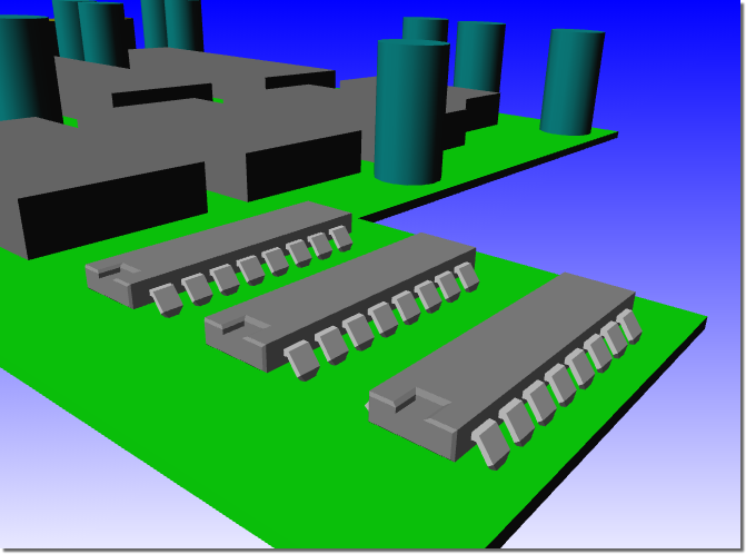
Figure 4 shows a typical IC mask layout
(Chip Editor) session.
Figure 4: Bartels AutoEngineer ASIC/IC Design
The following figures show the hierarchical structure of the
Bartels AutoEngineer object oriented Design DataBase (DDB). All design objects are stored in a single file, and each design object belongs to a certain class (e.g., drawing, symbol, etc.) and can inherit (include) symbols from the same or from other classes depending on the design context. Database and design objects can be manipulated independently from other objects and may be copied, extracted, included or deleted as required. The database knows about the design relations, i.e., copying a schematic sheet automatically copies inherited part and pin symbols. All database files, design or library, have the same file format. Whether a file is a design or a library file depends on its (contextual) content rather than on its file structure.
Figure 1 explains the schematic capture graphical object relations:
Figure 1: SCM Database Hierarchy
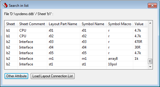
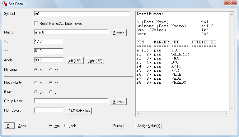
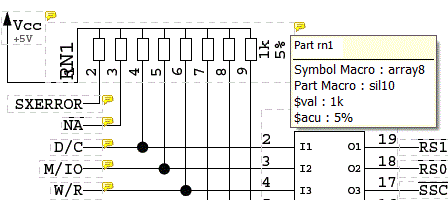
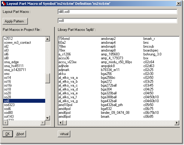
Figure 2 shows the relations between the logical and physical parts as well as an example for pin/gate/group swap information and power supply pins. This description can also be used to specify a fully hierarchical design, e.g., for ASICs or custom ICs:
Figure 2: Part Data Sheet with Loglib Definition
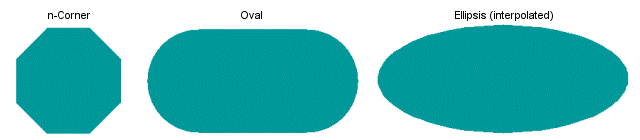
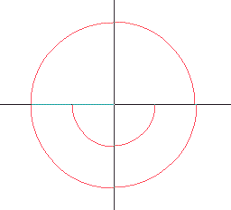
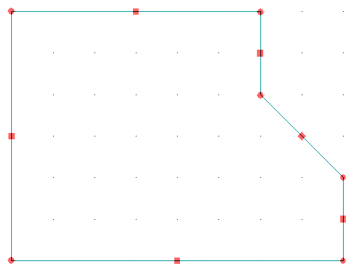
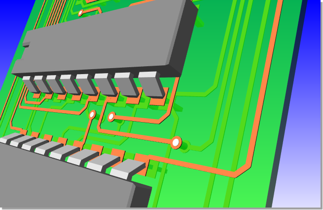
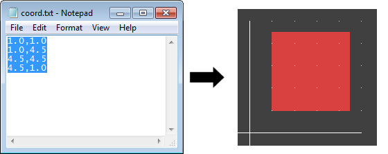
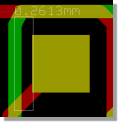
Figure 3 illustrates the construction of a printed circuit board. Arbitrarily shaped polygons can be created in any design hierarchy level. A polygon may also contain arcs, which are handled by the system as basic element types, i.e., all arc calculations are precise without using arc interpolation:
Figure 3: Layout Database Hierarchy
Figure 4 explains the overall dataflow within the complete design system including schematic capture and PCB design. Consider the central position of the
Job File which, at the end of the design process, contains all design-specific objects such as the schematic sheets, the PCB layout, the netlist data, and the job-specific library data:
Figure 4: Bartels AutoEngineer System Flow Diagram
Please note that the same design file which contains all SCM and PCB data may also contain part lists or other table-oriented information. The
Bartels AutoEngineer database software includes an SQL engine which is able to bundle SQL table information transparently into its own object class and automatically build indices for quick database access. SQL database access optimization works with multiple tables, too. All database queries, whether to objects or via the SQL engine, are processed by a powerful variable key-length B-TREE algorithm. It is not necessary to copy symbol and/or part libarary data directly onto a schematic plan and/or a PCB layout, the schematic plan and the PCB layout objects only store (placement data) references to the placed symbols and/or parts. Library symbols and parts are copied into the design file when they are requested for placement for the first time. This automatically creates design-specific symbol and part libraries within the design file and leaves the designer with the opportunity to modify design-specific library elements without changing the original (master) library. The backup of a design is also much simplified, since a single DDB file ends up containing the complete SCM and PCB design and library data.
The
Bartels Autorouter® was the first PC based protected mode rip-up/retry router. It is still the only one with selective Rip-Up/Cleanup/Backtracking. Previous versions were known as
Superoute of which thousands of licenses were sold worldwide.
Superoute modules were also modified by some source code OEM customers. Routers sold today under the name
Superoute no longer represent Bartels latest routing technology.
Bartels is the original source for all of the OEM versions resulting from more than 15 OEM contracts. The latest
Bartels Autorouter® version is integrated in the
Bartels AutoEngineer® CAD/CAE system.
- Rip-Up/Retry Router with AI Backtracking.
- Intelligent routing provides high quality results.
- Backtracking allows the router to try several different solutions before committing to one. E.g., the router may remove a bunch of intersecting traces, trying an alignment without the risk of losing the previously best solution.
- Unique selective Rip-Up/Retry algorithm, superset of global Rip-Up and Shove.
- Unique selective Clean-Up algorithm.
- Any (user selectable) grid, sub-grid (between traces) routing, mixture of different grids, gridless pad connections.
- Net-oriented product, full T-connection support, incomplete traces for SMT-via preplacement.
- User selectable individual net/trace constraints for, e.g., width, length, structure, distance, priority.
- Real working optimization for really manufacturable PCB designs. Cross-net optimization (Cleanup).
- Automatic redesign of existing projects, stop, leave and/or re-start at any time (Re-Entrant routing).
- On-screen visible routing, rip-up, etc. Numerous user-controlled modes and routing cost factors.
- Supports any geometry of items including curved traces, polygon-with-arc obstacles and blind/buried/staggered vias with floating point accuracy.
- Rule based routing using Neural Net Technology.
- Both cell and shape based Routing algorithms, based on priority trees.
- Optional automatic Pin/Gate Swap during Routing.
- Optional Autoplacement.
- Bartels Autorouter® - Routing Examples
The router supports gridless placement of pads, obstacles and traces, cell based routing grid, routing with one or multiple cells in width to existing on-grid or off-grid pads and on-grid or off-grid traces. The off-grid feature is a combination of grid-based and gridless routing technologies and does off-grid routing of traces even in a cell-based environment, making it the ideal combination between cell-based and shape-based technologies.
Integrated with the BAE schematic and PCB rule system, the
Bartels AutoEngineer supports automatic assignment of net classes based on library part/pin classifications and schematic tags to the actual design. Together with rules assigned to PCB areas, this allows for board design with EMC (Electromagnetic Compatibility) rules application.
Increased use of SMT fine pitch parts has created a demand for a flexible grid routing technology. The previous versions of the
Bartels AutoEngineer used the following data representation:
- A one byte per cell per layer routing matrix (any basic grid may be chosen)
- Integer (matrix) coordinates routed trace representation
- Indexed floating point trace anchors (e.g., to fixed off-grid traces)
- Floating point fixed trace representation
- Floating point polygon pin and obstacle representation
In this case floating point coordinates permit what is called a "gridless" (shape/contour) representation. This database supports true floating point polygons/polylines including arcs for all data including prerouted fixed traces, however, with the exception of currently routed traces. The router can connect to off-grid junction points, including pins and fixed traces.
With the introduction of the sub-grid mode, the on-grid limit for routed traces was relaxed to half-grid (one-half) shifted traces, thus permitting proper handling of fine pitch SMT. However, this mode requires additional matrix memory and more computing time.
Competing products claiming to be "gridless" choose a multi-way (mostly four-way) geometrical tree approach which ends up in rectangular leafs. The advantage of this data representation is that rectangular data may indeed be represented with high resolution and routing is fast if trace and corner density is low. However, for high-density boards it requires even more memory than a matrix-based approach, and access time for allocation checks at certain board positions can increase excessively. The greatest pitfall, however, is the lack of efficient facilities for joining neighbouring rectangles, thus layout quality in true gridless mode often deteriorates dramatically, with 100% routing results becoming exceptional. This is especially true for non-rectangular (e.g., polygon) obstacles and 45 degree routing.
Our solution is to keep the matrix at the lowest possible density for strategic routing purposes, and to do the final artwork on a gridless database.
The
Bartels Autorouter V6.0 maintains a floating point database for routed traces parallel to the integer/matrix representation (dual database). The matrix allows for efficient routing and rip-up/retry with high quality results even for highest trace and/or ratsnet density. The floating point contour/shape routing database results in efficient board space usage by finding off-grid SMT channels and high quality SMT pad connections including long distance off-grid routing where required and/or applicable. The dual database combines the advantages of both concepts, thus giving significant improvement over both pure matrix and pure shape-based routing. The strategic trace routing is done via the matrix, thus both the advanced Lee algorithm which guarantees to find the least cost optimum way for a single trace, and the Bartels RipUp and CleanUp algorithms which detect optimum traces for rip-up and cleanup, can be used together with a non-rectangular shape-based database.
The dual database is an open end development. One of the next steps will be simultaneous maintenance of multiple routing matrices to reach even higher quality on mixed analog/digital boards. Further developments could yield the selective placement adjustment for certain parts to combine and thus gain additional trace channels.
The
Bartels Autorouter V6.0 is also called the
Neural Router because it may be combined with the
Bartels Rule System. The
Rule System applies one or more rules to system objects such as parts or traces. The rules are defined using a language similar to Prolog, however, with special operators to find not only all possible, but also optimum solutions to design-specific rule system queries or output requests.
The rules may be defined and assigned to individual items such as parts, nets, or traces as well as for the overall system, e.g., for cost factor and routing strategy control.
As the
Rule System uses a novel neural net approach to focus the rule evaluation on the probably best path, the
Bartels AutoEngineer combined with the
Rule System is called the
Bartels Neural Autorouter™.
The
Bartels Autorouter V6.0 implements the pin/gate/group swap within the router depending on the routing results. If enabled, this feature permits routing of even the most complex boards, because the router gains an additional degree of freedom. The swaps done by the
Autorouter are reported by the output interface and
requests for correlating the schematic plan are automatically stored with the design.
Together with the introduction of the pin/gate/group swaps, a part-oriented input interface was implemented to permit placement optimizations by the router in future versions. The interface now maintains an additional attribute field (trace/via ident code) to support rather specific definitions such as traces on part level, a BAE-specific feature widely used for defining printed inductors.
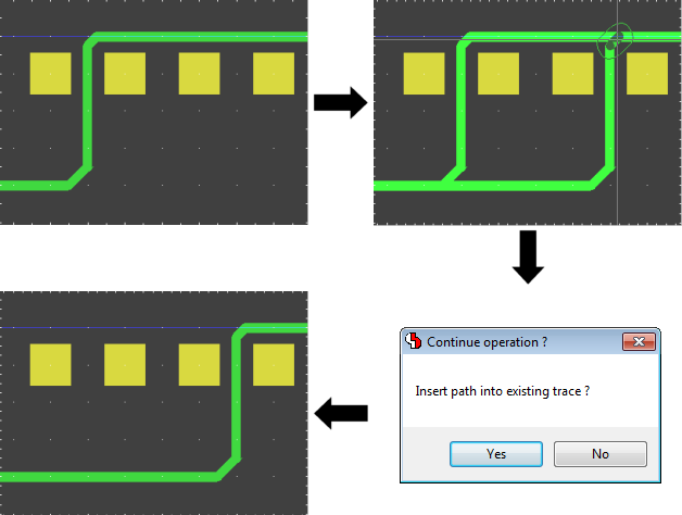
A documented interactive routing functions interface is provided to implement the interactive single net/part routing features through the standard interface (used by the
Neural Autorouter module).
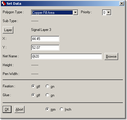
In addition to standard negative power planes and copper and copper pour areas, the
Autorouter now also supports split hierarchical negative power planes.
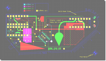
The following images shows some examples of PCB designs which were automatically routed with the
Bartels Autorouter®.
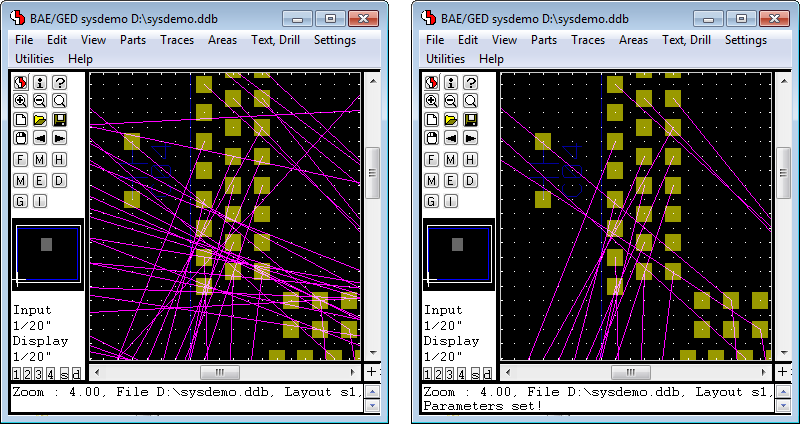
Figure 1a displays a medium size conventional printed circuit board with some manually pre-routed critical traces and power supply connections:
Figure 1a: Bartels Autorouter Application Example - Medium Size Conventional Board (unrouted)
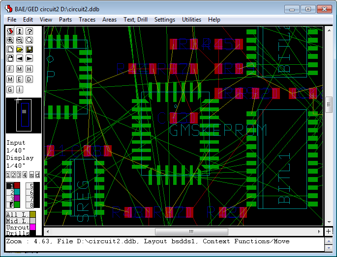
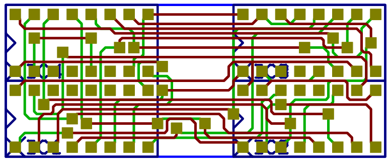
Figure 1b shows the automatically routed version of the PCB layout from
figure 1a. The
Autorouter used four signal layers and two power planes:
Figure 1b: Bartels Autorouter Application Example - Medium Size Conventional Board (automatically routed)
This document highlights some of the new features introduced with the Bartels AutoEngineer Version 8.0.
Labels included in Net Highlight - with Highlight Focus
 |
This document highlights some of the new features introduced with the Bartels AutoEngineer Version 7.8.
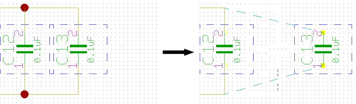
Clipboard - Attribute Transfer
 |
Clipboard - Coordinate Transfer
 |
This document highlights some of the new features introduced with the Bartels AutoEngineer Version 7.6.
This document highlights some of the new features introduced with the Bartels AutoEngineer Version 7.4.
Left Treeview Menu Display
 |
Right Treeview Menu Display
 |
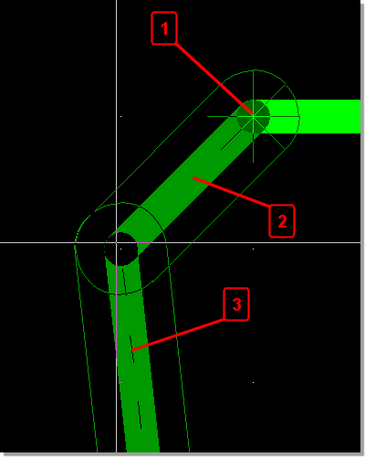 |
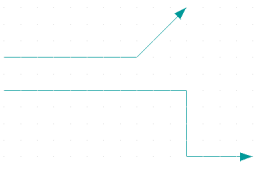
- Angle Direction Marker
- Solid display for segment placed by setting corner point
- Dashed display for segment processed after corner point
|
Separate X/Y Coordinates
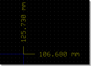 |
X/Y Coordinate Pair
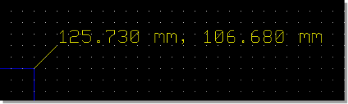 |
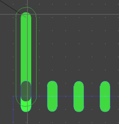
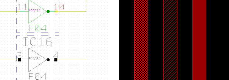
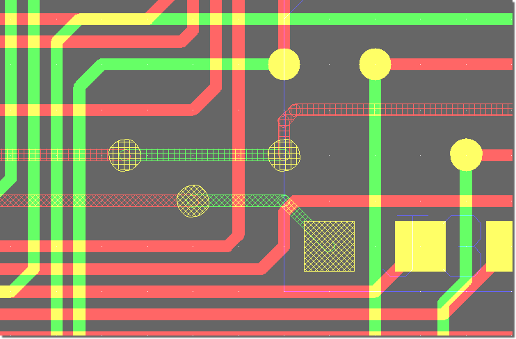
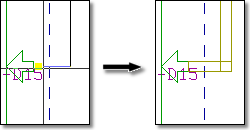
Schematic Plan Differential Pair Marker
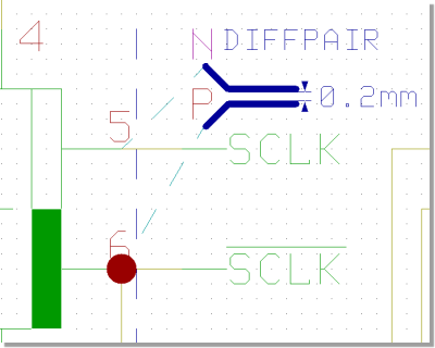 |
Layout Pair Partner Hatch Highlight and Parallel Trace Display
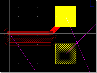 |
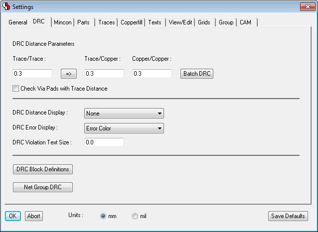
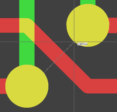
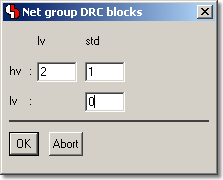
DRC Error Marker
with Distance Display
 |
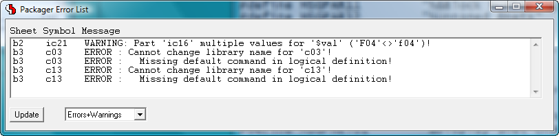
DRC Error Report
with Distance Display
 |
This document highlights some of the new features introduced with the Bartels AutoEngineer Version 7.2.
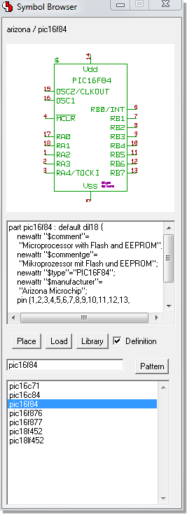
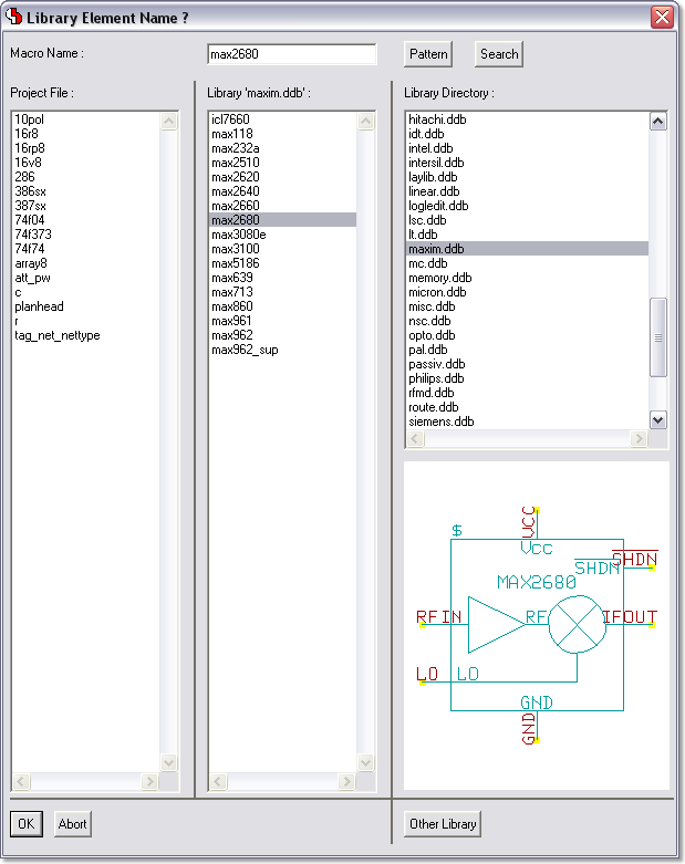
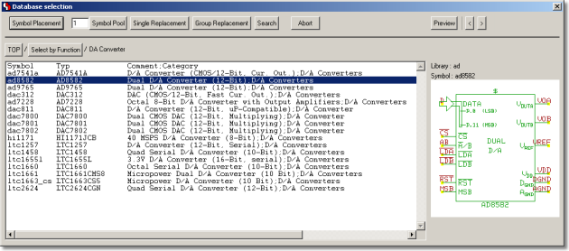
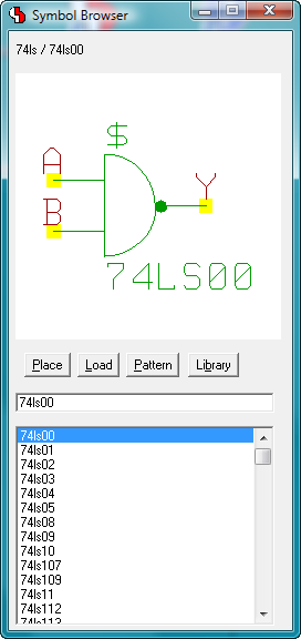
Symbol Browser
 |
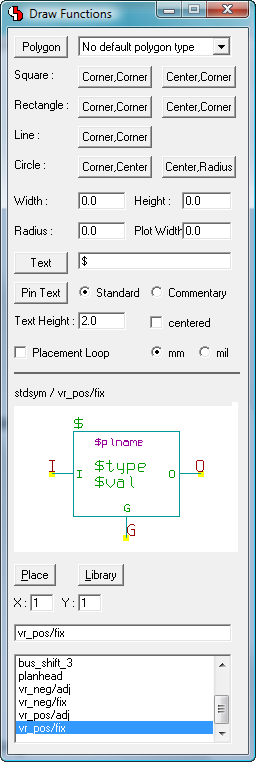
Draw Assistant
 |
Favorites Dialog
 |
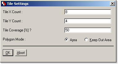
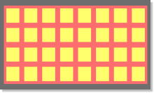
Create/Edit Polygon...
 |
...
 |
View Layout Component Side
 |
View Layout Solder Side
 |
This document highlights some of the new features introduced with the Bartels AutoEngineer Version 7.0.
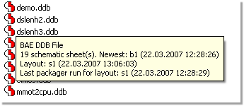
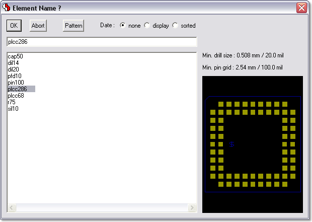
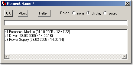
File Contents Info during File Selection | 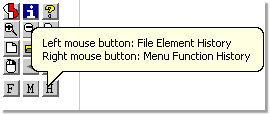
Toolbar Function Tooltips |
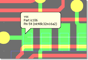
Element Info (optional) |
| 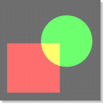
Polygons |
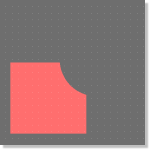
Cut Out |

Contour |
Intersection |
| 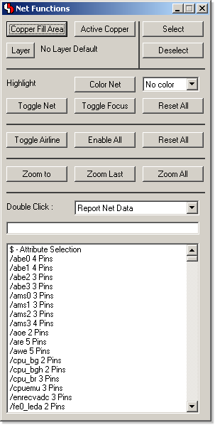 |
Modeless Layout Editor dialog with
net-specific
functions. |
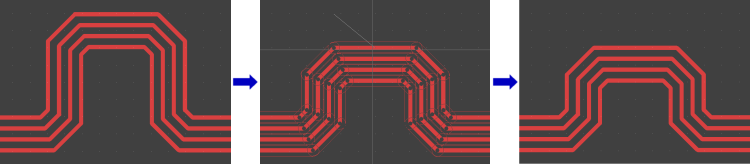
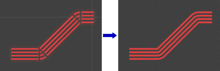
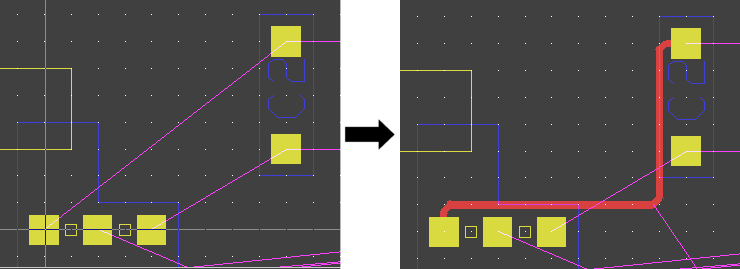
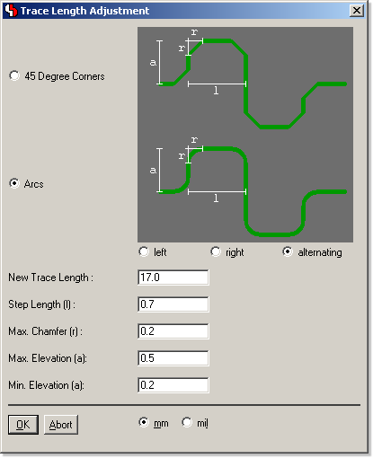
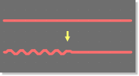
| Signal Phase Shift Display
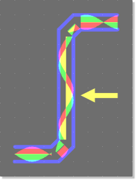 |
Phase Shift Compensation through Trace Length Adjustment
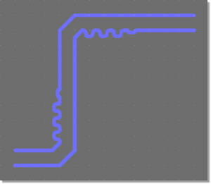 |
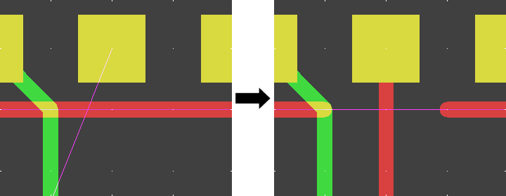
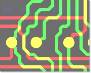
Gridless routing alongside obstacle edges
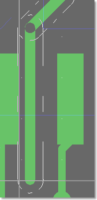 |
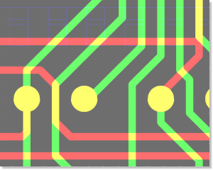
Trace centered between obstacles
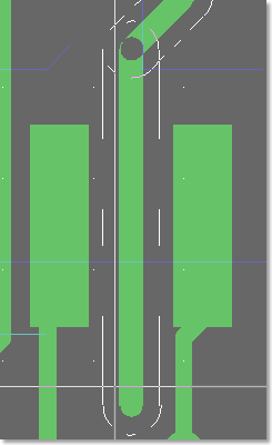 |
Pin Assignments Table
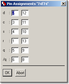 |
Pin Assignments graphically
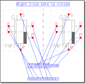 |
SMD Pin Routing prior to BAE V6.6
 |
SMD Pin Routing in BAE V6.6
 |
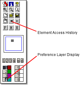
SCM Toolbar Buttons for Quick Drawing Function Access
 |
Layout Toolbar Buttons for Quick Documentary Layer Access
 |
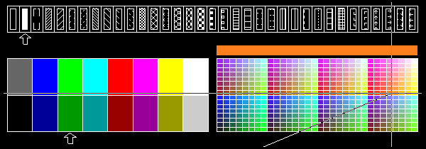
Layout Toolbar Buttons for Color Table Management and Access
 |
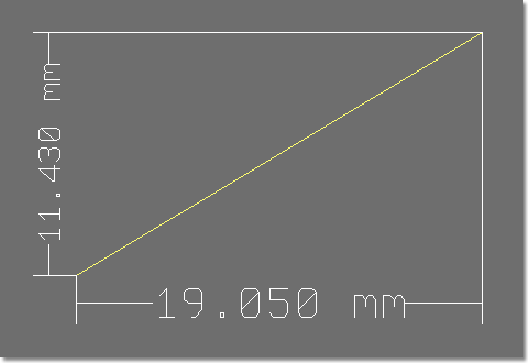
Formula Input...
 |
...is automatically calculated
 |
Highligh Focus Off
 |
Highlight Focus On
 |
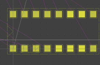
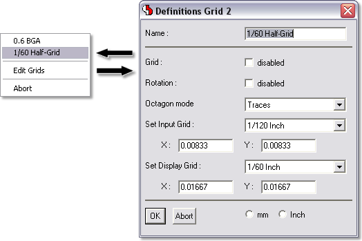
Bus Tap Row Definition
 |
Bus Tap Row Placement
 |
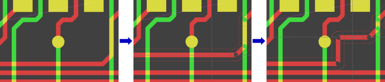
BGA Via Fanout Routing
 |
Microvias - Via-in-Pin Routing
 |
Increased Multilayer Visibility
 |
Overlapping Fill Area Outlines visible
 |
only Values visible
 |
Values and Pin Names visible
 |
only Pin Names visible
 |
e.g., for Milling Contour Generation
 |
Displaying swappable Pins/Gates...
 |
...and possible Swap Partners
 |
DRC Error Listing...
 |
...and Zoom to Selected Error
 |
delay in BAE Professional
 |
instant response in BAE HighEnd
 |
deleting power signal area
in BAE Professional
 |
deleting power signal area
in BAE HighEnd
 |
highlighting all short-circuit net elements
in BAE Professional
 |
selective short-circuit highlight
in BAE HighEnd
 |
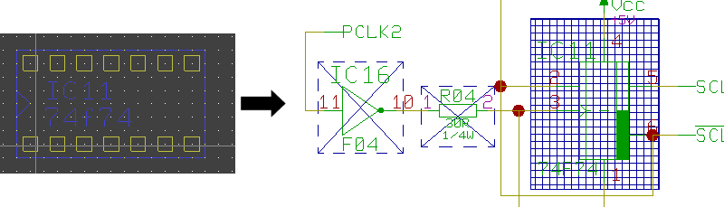
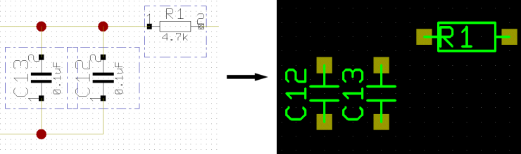
layout part selection...
 |
...and automatic zoom to SCM symbol
 |
SCM symbol group selection...
 |
...to select corresponding layout parts
 |
select SCM symbol...
 |
...and place corresponding layout part
 |
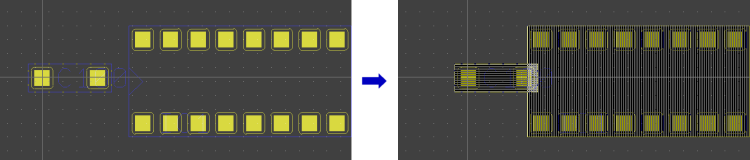
group-select SCM symbols and...
 |
...autoplace corresponding layout part set
 |
Bartels AutoEngineer® - Product Information
© 1985-2025 Oliver Bartels F+E • Updated: 12 April 2004, 14:37 [UTC]
|