| Welcome to the Bartels Group of Companies |
 |
|
Bartels AutoEngineer®Bartels AutoEngineer® (BAE) is a famous EDA/CAE/CAD/CAM software system for schematic capture, printed circuit board design and IC/ASIC design. Bartels AutoEngineer® software runs under Microsoft Windows, Linux and various X11/Unix systems. Look for yourself why more and more well-known companies - ranging from A like Alcatel (GSM) to Z like Zytek (motor sports) - are using Bartels AutoEngineer® software for the design and development of complex state-of-the-art electronic modules and components.
Last Change
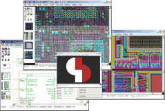
The following pictures show typical screen shots of the Bartels AutoEngineer® software. The basic BAE user interface is identical on the supported platforms. However, through the User Language which is freely available with every BAE system, the features for customizing the menu layout and adding new functions virtually unlimited. We are encouraging and supporting users in adapting the menu to their special requirements. I.e., customer-specific BAE menus are commonplace...
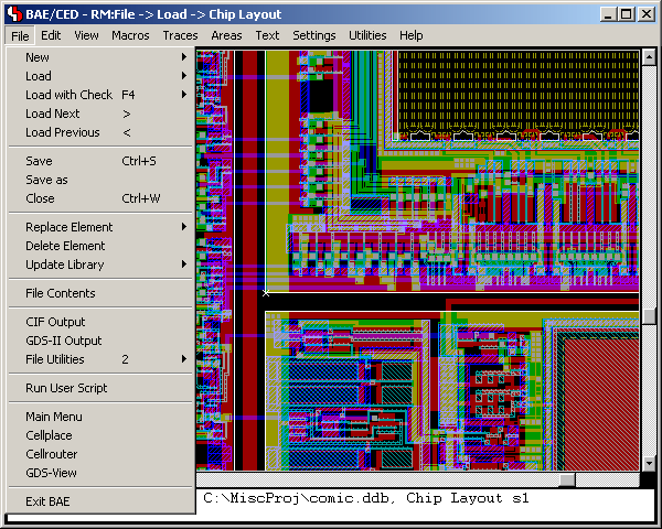
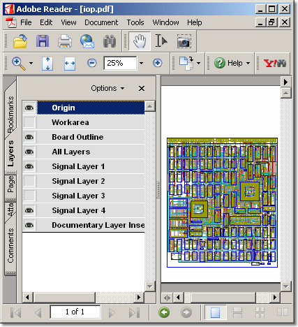
Figure 1 shows a screen shot from the BAE HighEnd main menu screen on Windows XP. The function starts additional processes coupled with the current process, thus allowing for inter-module communications such as cross-highlighting between the Schematic Editor and the PCB Layout Editor. The CAM View module including Gerber viewer, panelization functions and manufacturing data optimizers is provided with every AutoEngineer layout system at no additional cost. The menu below also shows the function for activating the optional IC/ASIC Design system:
Figure 1: Bartels AutoEngineer HighEnd Main Menu
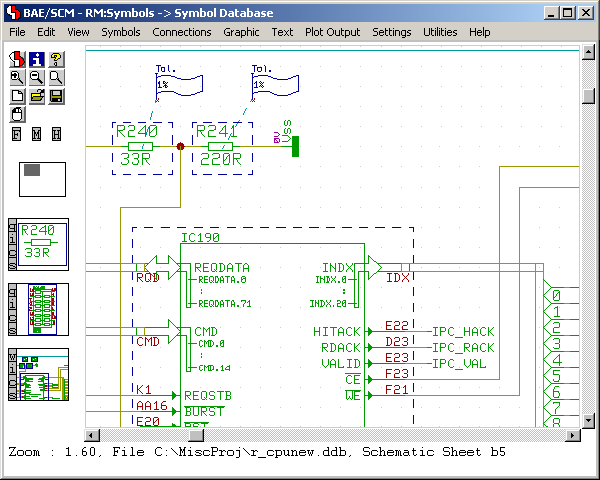
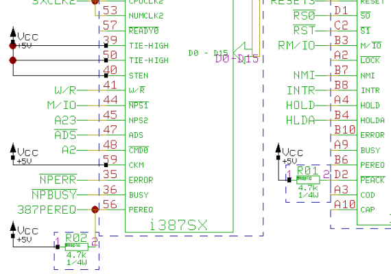
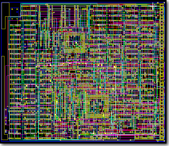
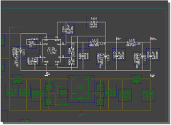
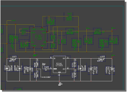
Figure 2 shows a typical Schematic Capture session. The toolbar at the left provides buttons for frequently used display and file functions, design view management facilities, and a feature for automatic part attribute settings, all of which is designed and can be fully customized through User Language. Please note the resistor attributes and the bus connection to the processor IC in the schematic plan. The system automatically connects the individual bus lines based on the logical library description:
Figure 2: Bartels AutoEngineer Schematic Capture
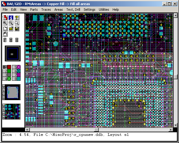
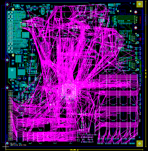
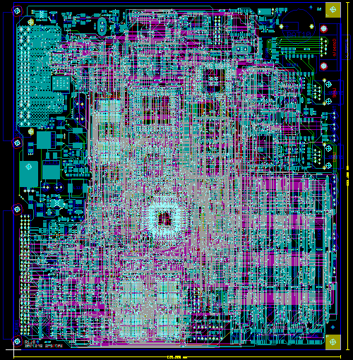
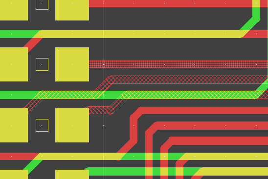
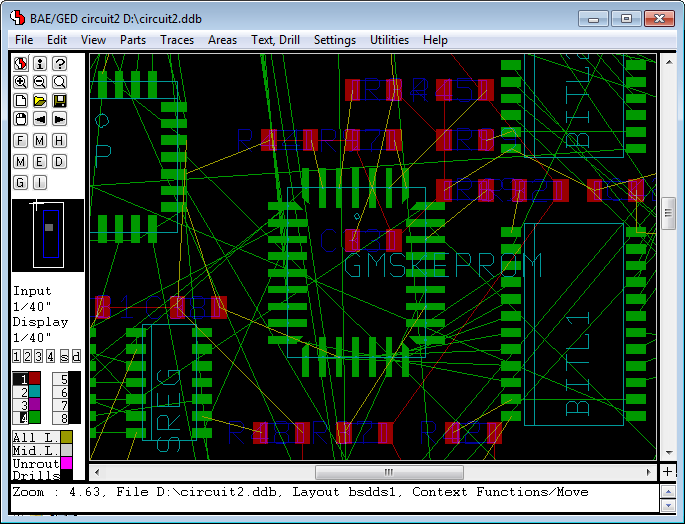
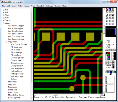
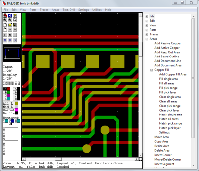
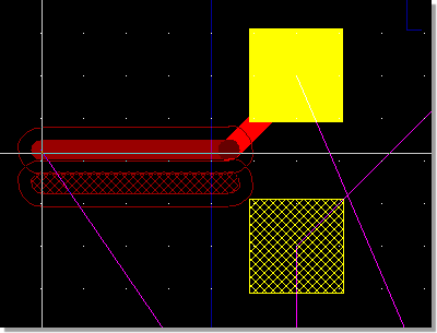
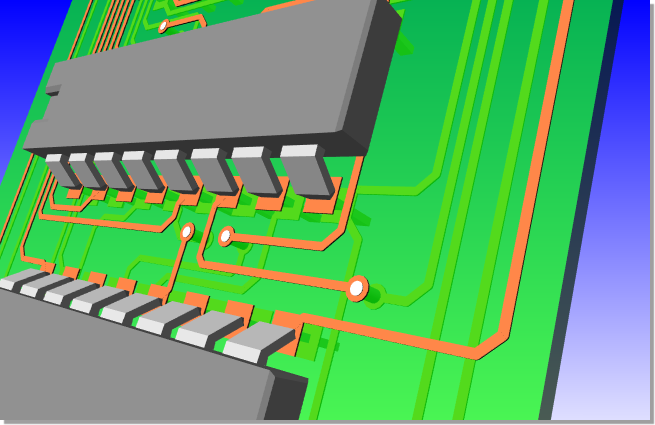
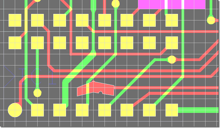
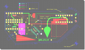
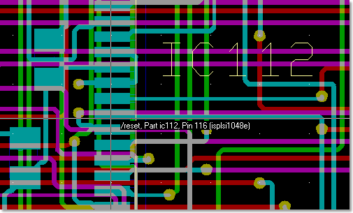
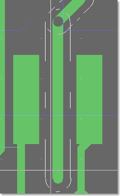
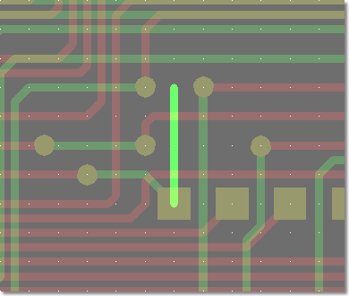
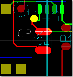
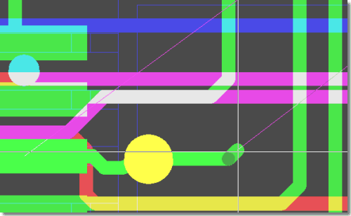
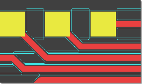
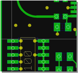
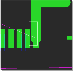
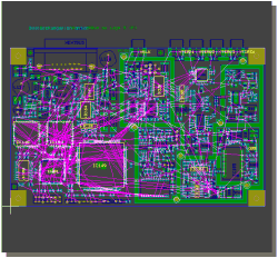
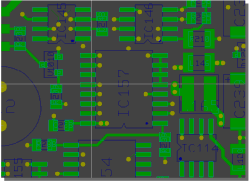
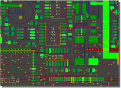
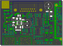
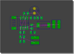
Figure 3 shows a typical PCB Layout Editor window. The PCB layout displayed shows a mixture of possible design options, such as the use of surface mounted devices (SMDs), curved traces, negative split power planes, positive copper pour areas, irregular pad and copper shapes, etc. The DRC is able to handle all these online and in real time, as it is based on an incremental technology which also allows for multi-step . The toolbar on the lefthand side is designed with User Language and provides design view management facilities and buttons for frequently used display and file access functions:
Figure 3: Bartels AutoEngineer PCB Layout
An IC design module including real-time mask connectivity, GDS2 I/O, Standard Cell Placement with intelligent algorithms as well as routing using the Bartels AutoEngineer in its IC design version is available as an option. Figure 4 shows a typical IC mask layout (Chip Editor) session.
Figure 4: Bartels AutoEngineer ASIC/IC Design
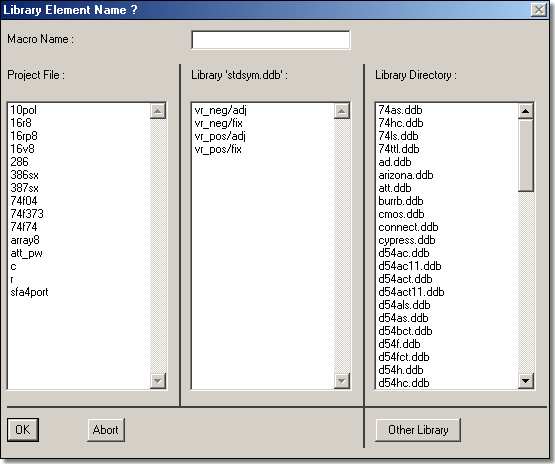
The following figures show the hierarchical structure of the Bartels AutoEngineer object oriented Design DataBase (DDB). All design objects are stored in a single file, and each design object belongs to a certain class (e.g., drawing, symbol, etc.) and can inherit (include) symbols from the same or from other classes depending on the design context. Database and design objects can be manipulated independently from other objects and may be copied, extracted, included or deleted as required. The database knows about the design relations, i.e., copying a schematic sheet automatically copies inherited part and pin symbols. All database files, design or library, have the same file format. Whether a file is a design or a library file depends on its (contextual) content rather than on its file structure.
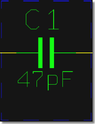
Figure 1 explains the schematic capture graphical object relations:
Figure 1: SCM Database Hierarchy
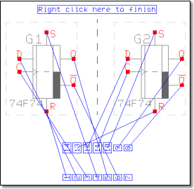
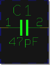
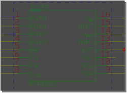
Figure 2 shows the relations between the logical and physical parts as well as an example for pin/gate/group swap information and power supply pins. This description can also be used to specify a fully hierarchical design, e.g., for ASICs or custom ICs:
Figure 2: Part Data Sheet with Loglib Definition
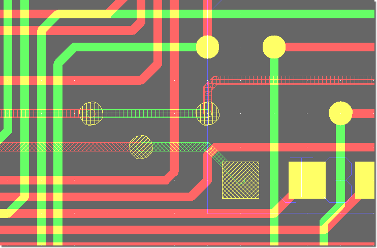
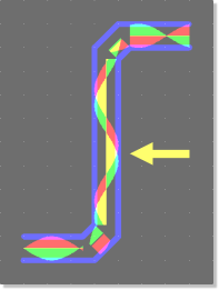
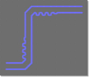
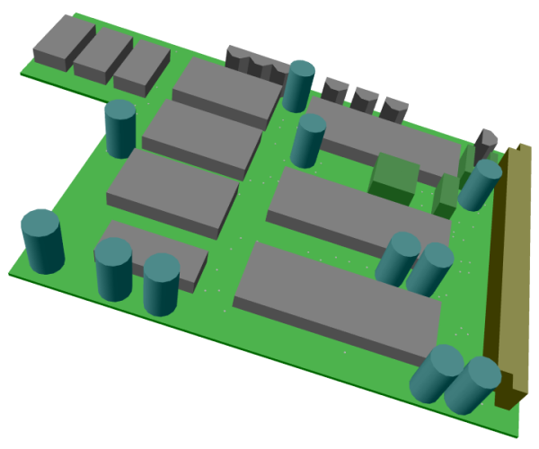
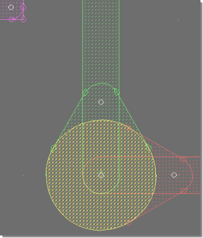
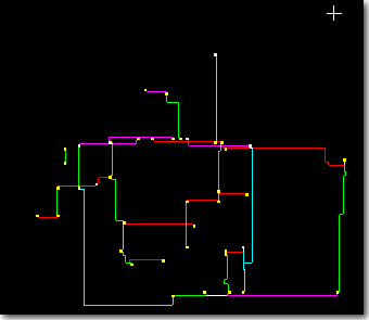
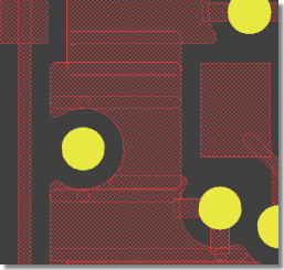
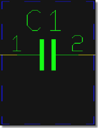
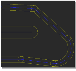
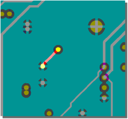
Figure 3 illustrates the construction of a printed circuit board. Arbitrarily shaped polygons can be created in any design hierarchy level. A polygon may also contain arcs, which are handled by the system as basic element types, i.e., all arc calculations are precise without using arc interpolation:
Figure 3: Layout Database Hierarchy
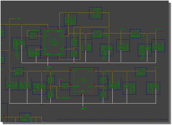
Figure 4 explains the overall dataflow within the complete design system including schematic capture and PCB design. Consider the central position of the
Figure 4: Bartels AutoEngineer System Flow Diagram Please note that the same design file which contains all SCM and PCB data may also contain part lists or other table-oriented information. The Bartels AutoEngineer database software includes an SQL engine which is able to bundle SQL table information transparently into its own object class and automatically build indices for quick database access. SQL database access optimization works with multiple tables, too. All database queries, whether to objects or via the SQL engine, are processed by a powerful variable key-length B-TREE algorithm. It is not necessary to copy symbol and/or part libarary data directly onto a schematic plan and/or a PCB layout, the schematic plan and the PCB layout objects only store (placement data) references to the placed symbols and/or parts. Library symbols and parts are copied into the design file when they are requested for placement for the first time. This automatically creates design-specific symbol and part libraries within the design file and leaves the designer with the opportunity to modify design-specific library elements without changing the original (master) library. The backup of a design is also much simplified, since a single DDB file ends up containing the complete SCM and PCB design and library data.
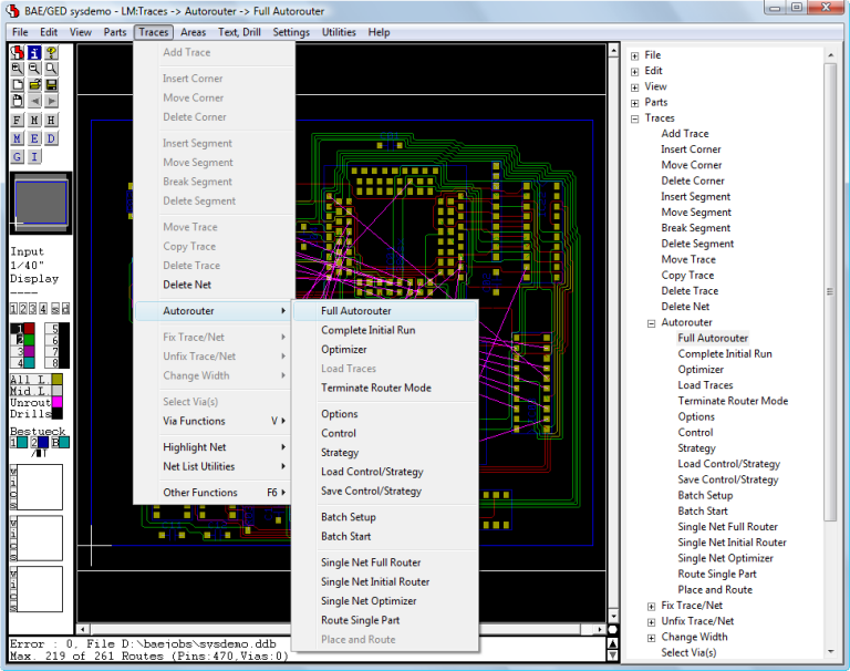
The Bartels Autorouter® was the first PC based protected mode rip-up/retry router. It is still the only one with selective Rip-Up/Cleanup/Backtracking. Previous versions were known as Superoute of which thousands of licenses were sold worldwide. Superoute modules were also modified by some source code OEM customers. Routers sold today under the name Superoute no longer represent Bartels latest routing technology. Bartels is the original source for all of the OEM versions resulting from more than 15 OEM contracts. The latest Bartels Autorouter® version is integrated in the Bartels AutoEngineer® CAD/CAE system.
The router supports gridless placement of pads, obstacles and traces, cell based routing grid, routing with one or multiple cells in width to existing on-grid or off-grid pads and on-grid or off-grid traces. The off-grid feature is a combination of grid-based and gridless routing technologies and does off-grid routing of traces even in a cell-based environment, making it the ideal combination between cell-based and shape-based technologies.
Integrated with the BAE schematic and PCB rule system, the Bartels AutoEngineer supports automatic assignment of net classes based on library part/pin classifications and schematic tags to the actual design. Together with rules assigned to PCB areas, this allows for board design with EMC (Electromagnetic Compatibility) rules application.
Increased use of SMT fine pitch parts has created a demand for a flexible grid routing technology. The previous versions of the Bartels AutoEngineer used the following data representation:
In this case floating point coordinates permit what is called a "gridless" (shape/contour) representation. This database supports true floating point polygons/polylines including arcs for all data including prerouted fixed traces, however, with the exception of currently routed traces. The router can connect to off-grid junction points, including pins and fixed traces. With the introduction of the sub-grid mode, the on-grid limit for routed traces was relaxed to half-grid (one-half) shifted traces, thus permitting proper handling of fine pitch SMT. However, this mode requires additional matrix memory and more computing time. Competing products claiming to be "gridless" choose a multi-way (mostly four-way) geometrical tree approach which ends up in rectangular leafs. The advantage of this data representation is that rectangular data may indeed be represented with high resolution and routing is fast if trace and corner density is low. However, for high-density boards it requires even more memory than a matrix-based approach, and access time for allocation checks at certain board positions can increase excessively. The greatest pitfall, however, is the lack of efficient facilities for joining neighbouring rectangles, thus layout quality in true gridless mode often deteriorates dramatically, with 100% routing results becoming exceptional. This is especially true for non-rectangular (e.g., polygon) obstacles and 45 degree routing. Our solution is to keep the matrix at the lowest possible density for strategic routing purposes, and to do the final artwork on a gridless database. The Bartels Autorouter V6.0 maintains a floating point database for routed traces parallel to the integer/matrix representation (dual database). The matrix allows for efficient routing and rip-up/retry with high quality results even for highest trace and/or ratsnet density. The floating point contour/shape routing database results in efficient board space usage by finding off-grid SMT channels and high quality SMT pad connections including long distance off-grid routing where required and/or applicable. The dual database combines the advantages of both concepts, thus giving significant improvement over both pure matrix and pure shape-based routing. The strategic trace routing is done via the matrix, thus both the advanced Lee algorithm which guarantees to find the least cost optimum way for a single trace, and the Bartels RipUp and CleanUp algorithms which detect optimum traces for rip-up and cleanup, can be used together with a non-rectangular shape-based database. The dual database is an open end development. One of the next steps will be simultaneous maintenance of multiple routing matrices to reach even higher quality on mixed analog/digital boards. Further developments could yield the selective placement adjustment for certain parts to combine and thus gain additional trace channels.
The Bartels Autorouter V6.0 is also called the Neural Router because it may be combined with the Bartels Rule System. The Rule System applies one or more rules to system objects such as parts or traces. The rules are defined using a language similar to Prolog, however, with special operators to find not only all possible, but also optimum solutions to design-specific rule system queries or output requests. The rules may be defined and assigned to individual items such as parts, nets, or traces as well as for the overall system, e.g., for cost factor and routing strategy control. As the Rule System uses a novel neural net approach to focus the rule evaluation on the probably best path, the Bartels AutoEngineer combined with the Rule System is called the Bartels Neural Autorouter™.
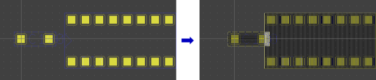
The Bartels Autorouter V6.0 implements the pin/gate/group swap within the router depending on the routing results. If enabled, this feature permits routing of even the most complex boards, because the router gains an additional degree of freedom. The swaps done by the Autorouter are reported by the output interface and requests for correlating the schematic plan are automatically stored with the design. Together with the introduction of the pin/gate/group swaps, a part-oriented input interface was implemented to permit placement optimizations by the router in future versions. The interface now maintains an additional attribute field (trace/via ident code) to support rather specific definitions such as traces on part level, a BAE-specific feature widely used for defining printed inductors. A documented interactive routing functions interface is provided to implement the interactive single net/part routing features through the standard interface (used by the Neural Autorouter module). In addition to standard negative power planes and copper and copper pour areas, the Autorouter now also supports split hierarchical negative power planes.
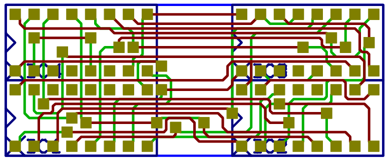
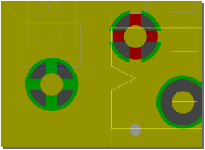
The following images shows some examples of PCB designs which were automatically routed with the Bartels Autorouter®.
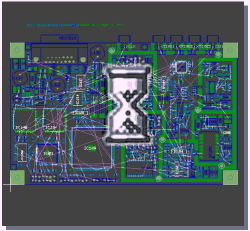
Figure 1a displays a medium size conventional printed circuit board with some manually pre-routed critical traces and power supply connections:
Figure 1a: Bartels Autorouter Application Example - Medium Size Conventional Board (unrouted) Figure 1b shows the automatically routed version of the PCB layout from figure 1a. The Autorouter used four signal layers and two power planes:
Figure 1b: Bartels Autorouter Application Example - Medium Size Conventional Board (automatically routed)
This document highlights some of the new features introduced with the Bartels AutoEngineer Version 8.0.
This document highlights some of the new features introduced with the Bartels AutoEngineer Version 7.8.
This document highlights some of the new features introduced with the Bartels AutoEngineer Version 7.6.
This document highlights some of the new features introduced with the Bartels AutoEngineer Version 7.4.
This document highlights some of the new features introduced with the Bartels AutoEngineer Version 7.2.
This document highlights some of the new features introduced with the Bartels AutoEngineer Version 7.0.
Prices effective as of November 4th, 2013 and correct at time of going to press. All prices are shown in European Monetary Union (EMU) Euro currency, exclusive and inclusive of VAT. German VAT at 19% applies to all customers in Germany and to all EU customers without EC VAT Registration number. Software delivery is free of charge. All prices based on and displayed in Euro (EUR) and additionally/optionally displayed in the selected currency: Currently selected display: Euro (EUR). Prices displayed in other than Euro currencies (GBP, USD, etc.) are subject to exchange rate fluctuation and may have to be adjusted in line with the Euro exchange rate on the day of the purchase.
Notes BAE system prices (except for BAE Demo, BAE Schematics and BAE Light) are subject to discounts for multiple BAE systems/license purchases, universities, schools, students, etc. Please contact us with any enquiries regarding discounts. We reserve the right to change all prices without notice. The standard sales and delivery terms of Bartels System GmbH apply. Especially, all delivered goods remain our property until full payment of the invoiced amount. The European Copyright Directive applies, which means that duplication of the delivered software is not permitted except for backup purposes. We sell single per-piece non-exclusive licenses only. Place of court and jurisdiction is Munich, Germany. InquiriesYou can use the following form to send your inquiry via Email message to us, even if you don't have Email on your system. Please fill in the appropriate details, then press :
As Bartels AutoEngineer software is a professional EDA system, it requires quite some space even in its compressed form. We decided to focus on the Windows and Linux versions, which have relatively small binaries due to modern compression technology. Please contact us if you experience download problems, or if you are interested in BAE systems for other operating system platforms such as Sun Solaris. Please fill in and submit the following form to select the desired download:
The Bartels AutoEngineer® software is © copyrighted, the copyright belongs to Oliver Bartels F+E, Munich, Germany. The name Bartels AutoEngineer® is a registered trademark. The software is provided for evaluation purposes and exclusively under the law and jurisdiction of the Federal Republic of Germany with place of court at Munich, Germany. As this demo version is provided for free, there is no money back guarantee, however we are of course interested in bug reports to provide the highest quality software to our customers. But in no case shall we be responsible for indirect or consequential damages. German Legislation also means that the binding software copyright rules of the European Union apply, which prohibits unauthorized duplication of this copyrighted software by third parties. You also agree not to attempt to circumvent the restrictions of the Bartels AutoEngineer Demo version by altering the software or by using keys other than those provided by us. The software may not be redistributed in whole or in part without our prior written permission. You also agree that we do not permit or support the use of this software in countries to which its export is forbidden by German law. We are interested in mirroring sites, however we want to make sure that our customers always receive the latest version, thus the demand for permission. BAE Schematics is provided on an as is basis for internal use only. Commercial redistribution is expressly prohibited. By starting the download you agree to the above conditions and legislation. Please do not download the software if you do not agree to the above conditions or if your country does not permit the sole and binding application of German law and jurisdiction or does not permit the above mentioned liability limitations.
Bartels System currently provides the following Bartels AutoEngineer manuals and publications. Adobe Acrobat Reader is required for viewing and/or printing Adobe Portable Document Format (PDF) files. Bartels AutoEngineer® - Installation GuideThe Bartels AutoEngineer® - Installation Guide describes the Bartels AutoEngineer configurations and system requirements and provides detailed Bartels AutoEngineer installation instructions for all supported hardware and software platforms. Bartels AutoEngineer® - User ManualThe Bartels AutoEngineer® - User Manual describes in detail how to use the Bartels AutoEngineer CAE/CAD/CAM design system. The following main topics are covered by this manual:
Bartels AutoEngineer® - Symbol and Part LibrariesThe Bartels AutoEngineer® - Symbol and Part Libraries documentation contains detailed information about the symbol and part libraries provided with the Bartels AutoEngineer CAE/CAD/CAM design system. Bartels User Language - Programmer's GuideThe Bartels User Language - Programmer's Guide describes how to use the Bartels User Language in Bartels AutoEngineer, i.e., how it is integrated to the Bartels AutoEngineer EDA system and how it can be applied. The following main topics are covered by this manual:
Bartels AutoEngineer® - Update HistoryThe Bartels AutoEngineer® - Update History provides short information about the most important new features, enhancements and changes introduced by Bartels AutoEngineer update versions released since Bartels AutoEngineer Version 1.2. Forward compatibility from earlier versions to newer Bartels AutoEngineer versions is always ensured, but not backward compatibility. Bartels AutoEngineer® - Next Version - Release Notes - * Preliminary Information *The Bartels AutoEngineer® - Next Version - Release Notes - * Preliminary Information * provide detailed information about new features, enhancements, changes and bug-fixing introduced with the next Bartels AutoEngineer version. Forward compatibility from earlier versions to the latest Bartels AutoEngineer version is always ensured, but not backward compatibility. Bartels AutoEngineer® - Version 8.0 - Release NotesThe Bartels AutoEngineer® - Version 8.0 - Release Notes provide detailed information about new features, enhancements, changes and bug-fixing introduced with Bartels AutoEngineer Version 8.0. Forward compatibility from earlier versions to Bartels AutoEngineer Version 8.0 is ensured, but not backward compatibility. Bartels AutoEngineer® - Version 7.8 - Release NotesThe Bartels AutoEngineer® - Version 7.8 - Release Notes provide detailed information about new features, enhancements, changes and bug-fixing introduced with Bartels AutoEngineer Version 7.8. Forward compatibility from earlier versions to Bartels AutoEngineer Version 7.8 is ensured, but not backward compatibility. Bartels AutoEngineer® - Version 7.6 - Release NotesThe Bartels AutoEngineer® - Version 7.6 - Release Notes provide detailed information about new features, enhancements, changes and bug-fixing introduced with Bartels AutoEngineer Version 7.6. Forward compatibility from earlier versions to Bartels AutoEngineer Version 7.6 is ensured, but not backward compatibility. Bartels AutoEngineer® - Version 7.4 - Release NotesThe Bartels AutoEngineer® - Version 7.4 - Release Notes provide detailed information about new features, enhancements, changes and bug-fixing introduced with Bartels AutoEngineer Version 7.4. Forward compatibility from earlier versions to Bartels AutoEngineer Version 7.4 is ensured, but not backward compatibility. Bartels AutoEngineer® - Version 7.2 - Release NotesThe Bartels AutoEngineer® - Version 7.2 - Release Notes provide detailed information about new features, enhancements, changes and bug-fixing introduced with Bartels AutoEngineer Version 7.2. Forward compatibility from earlier versions to Bartels AutoEngineer Version 7.2 is ensured, but not backward compatibility. Bartels AutoEngineer® - Version 7.0 - Release NotesThe Bartels AutoEngineer® - Version 7.0 - Release Notes provide detailed information about new features, enhancements, changes and bug-fixing introduced with Bartels AutoEngineer Version 7.0. Forward compatibility from earlier versions to Bartels AutoEngineer Version 7.0 is ensured, but not backward compatibility. Bartels AutoEngineer® - Version 6.8 - Release NotesThe Bartels AutoEngineer® - Version 6.8 - Release Notes provide detailed information about new features, enhancements, changes and bug-fixing introduced with Bartels AutoEngineer Version 6.8. Forward compatibility from earlier versions to Bartels AutoEngineer Version 6.8 is ensured, but not backward compatibility. Bartels AutoEngineer® - Version 6.6 - Release NotesThe Bartels AutoEngineer® - Version 6.6 - Release Notes provide detailed information about new features, enhancements, changes and bug-fixing introduced with Bartels AutoEngineer Version 6.6. Forward compatibility from earlier versions to Bartels AutoEngineer Version 6.6 is ensured, but not backward compatibility. Bartels AutoEngineer® - Version 6.4 - Release NotesThe Bartels AutoEngineer® - Version 6.4 - Release Notes provide detailed information about new features, enhancements, changes and bug-fixing introduced with Bartels AutoEngineer Version 6.4. Forward compatibility from earlier versions to Bartels AutoEngineer Version 6.4 is ensured, but not backward compatibility. Bartels AutoEngineer® - Version 6.2 - Release NotesThe Bartels AutoEngineer® - Version 6.2 - Release Notes provide detailed information about new features, enhancements, changes and bug-fixing introduced with Bartels AutoEngineer Version 6.2. Forward compatibility from earlier versions to Bartels AutoEngineer Version 6.2 is ensured, but not backward compatibility. Bartels AutoEngineer® - Version 6.0 - Release NotesThe Bartels AutoEngineer® - Version 6.0 - Release Notes provide detailed information about new features, enhancements, changes and bug-fixing introduced with Bartels AutoEngineer Version 6.0. Forward compatibility from earlier versions to Bartels AutoEngineer Version 6.0 is ensured, but not backward compatibility. Bartels AutoEngineer® - Version 5.4 - Release NotesThe Bartels AutoEngineer® - Version 5.4 - Release Notes provide detailed information about new features, enhancements, changes and bug-fixing introduced with Bartels AutoEngineer Version 5.4. Forward compatibility from earlier versions to Bartels AutoEngineer Version 5.4 is ensured, but not backward compatibility. Bartels AutoEngineer® - Version 5.0 - Release NotesThe Bartels AutoEngineer® - Version 5.0 - Release Notes provide detailed information about new features, enhancements, changes and bug-fixing introduced with Bartels AutoEngineer Version 5.0. Forward compatibility from earlier versions to Bartels AutoEngineer Version 5.0 is ensured, but not backward compatibility. Bartels AutoEngineer® - Version 4.6 - Release NotesThe Bartels AutoEngineer® - Version 4.6 - Release Notes provide detailed information about new features, enhancements, changes and bug-fixing introduced with Bartels AutoEngineer Version 4.6. Forward compatibility from earlier versions to Bartels AutoEngineer Version 4.6 is ensured, but not backward compatibility. Bartels AutoEngineer® - Version 4.4 - Release NotesThe Bartels AutoEngineer® - Version 4.4 - Release Notes provide detailed information about new features, enhancements, changes and bug-fixing introduced with Bartels AutoEngineer Version 4.4. Forward compatibility from earlier versions to Bartels AutoEngineer Version 4.4 is ensured, but not backward compatibility. Bartels AutoEngineer® - Version 4.2 - Release NotesThe Bartels AutoEngineer® - Version 4.2 - Release Notes provide detailed information about new features, enhancements, changes and bug-fixing introduced with Bartels AutoEngineer Version 4.2. Forward compatibility from earlier versions to Bartels AutoEngineer Version 4.2 is ensured, but not backward compatibility. Bartels AutoEngineer® - Version 4.0 - Release NotesThe Bartels AutoEngineer® - Version 4.0 - Release Notes provide detailed information about new features, enhancements, changes and bug-fixing introduced with Bartels AutoEngineer Version 4.0. Forward compatibility from earlier versions to Bartels AutoEngineer Version 4.0 is ensured, but not backward compatibility. Bartels AutoEngineer® - Version 3.4 - Release NotesThe Bartels AutoEngineer® - Version 3.4 - Release Notes provide detailed information about new features, enhancements, changes and bug-fixing introduced with Bartels AutoEngineer Version 3.4. Forward compatibility from earlier versions to Bartels AutoEngineer Version 3.4 is ensured, but not backward compatibility.
The information contained in the Bartels AutoEngineer publications as well as the products and/or programs described therein are subject to change without notice and should not be construed as a commitment by Bartels System. Although Bartels System has gone to great effort to verify the integrity of the information provided with the Bartels AutoEngineer publications, these publications could contain technical inaccuracies or typographical errors. Bartels System shall not be liable for errors contained therein or for incidental consequential damages in connection with the furnishing, performance or use of this material. Bartels System appreciates readers' and/or users' comments in order to improve these publications and/or the products described therein. Changes are periodically made to the information therein. These changes will be incorporated in new editions of the Bartels AutoEngineer publications. All rights reserved. No part of the Bartels AutoEngineer publications may be reproduced, stored in a retrieval system, translated, transcribed or transmitted, in any form or by any means manual, electric, electronic, electromagnetic, mechanical, chemical, optical or otherwise without prior express written permission from Bartels System. Bartels AutoEngineer®, Bartels Router® and Bartels Autorouter® are registered trademarks of Bartels System. Bartels User Language™ and Bartels Neural Router™ are trademarks of Bartels System. All other products or services mentioned in this publication are identified by the trademarks or service marks of their respective companies or organizations.
The reader should be familiar with the following notations used throughout the Bartels AutoEngineer documentation:
The following acronyms are used throughout the Bartels AutoEngineer documentation:
Unless otherwise mentioned, the following symbolic conventions are used throughout the Bartels AutoEngineer documentation:
The character sequences mentioned above may regain original meaning when used in programming languages, interpreter languages, specification languages, syntax description languages, etc. Bartels AutoEngineer®
|
|||||||||||||||||||||||||||||||||||||||||||||||||||||||||||||||||||||||||||||||||||||||||||||||||||||||||||||||||||||||||||||||||||||||||||||||||||||||||||||||||||||||||||||||||||||||||||||||||||||||||||||||||||||||||||||||||||||||||||||||||||||||||||||||||||||||||||||||||||||||||||||||||||||||||||||||||||||||||||||||||||||||||||||||||||||||||||||||||||||||||||||||||||||||||||||||||||||||||||||||||||||||||||||||||||||||||||||||||||||||||||||||||||||||||||||||||||||||||||||||||||||||||||||||||||||||||||||||||||||||||||||||||||||||||||||||||||||||||||||||||||||||||||||||||||||||||||||||||||||||||||||||||||||||||||||||||||||||||||||||||||||||||||||||||||||||||||||||||||||||||||||||||||||||||||||||||||||||||||||||||||||||||||||||||||||||||||||||||||||||||||||||||||||||||||||||||||||||||||||||||||||||||||||||||||||||||||||||||||||||||||||||||||||||||||||||||||||||||||||||||||||||||||||||||||||||||||||||||||||||||||||||||||||||||||||||||||||||||||||||||||||||||||||||||||||||||||||||||||||||
| 1 | Bartels AutoEngineer Software Configurations |
| 1.1 | Bartels AutoEngineer Professional |
| 1.2 | Bartels AutoEngineer Light |
| 1.3 | Bartels AutoEngineer Economy |
| 1.4 | Bartels AutoEngineer HighEnd |
| 1.5 | Bartels AutoEngineer IC Design |
| 1.6 | Bartels AutoEngineer FabView |
| 2 | System Requirements |
| 2.1 | Processor and Operating System |
| 2.2 | Main Memory (RAM) |
| 2.3 | Hard Disk Drive |
| 2.4 | Video Adapter, Monitor |
| 2.5 | Pointing Device, Mouse |
| 2.6 | CD-ROM Drive |
| 2.7 | Special PC System Requirements |
| 2.8 | CAM Interfaces |
| 3 | Documentation |
| 4 | Installation Guide |
| 4.1 | System Files |
| 4.2 | Preparing for Update Installations |
| 4.3 | Software Security Module and License Files |
| 4.4 | Windows Installation |
| 4.5 | MS-DOS Installation |
| 4.6 | Linux Installation |
| 4.7 | UNIX Installation |
| 5 | Parameter Setup and Program Start |
| 5.1 | BAE System Parameter |
| 5.2 | User Language Programs, Menu Assignments, Key Bindings |
| 5.3 | BAE Program Start and DDB File Access |
| 5.4 | File Access Environment Variables |
| 5.5 | System File Access Environment Variables |
| 5.6 | Windows System Font Selection |
| Tables |
| 1 | BAE Hardware and Operating System Platforms |
| 2 | BAE System Files |
| 3 | BAE Software License Files |
| 4 | BAE Graphic Device Driver for MS-DOS |
| 5 | BAE System File Environment Variables |
Bartels AutoEngineer (BAE) is a fully integrated EDA software system with powerful CAE/CAD/CAM program modules for circuit design, PCB (printed circuit board) layout and IC/ASIC design. The system is based on the famous Bartels AutoEngineer which has been incorporated in most leading PCB layout systems throughout the world, setting new industrial standards of autorouting success and dramatically reducing the requirement for manual routing.
The following Bartels AutoEngineer software configurations are available:
All BAE software configurations are provided with the same user interfaces and support different languages (English, German, etc.). Bartels AutoEngineer features binary-compatible design data management on different host platforms, i.e., BAE design data can be transferred "as-is" between all supported hardware and/or operating system platforms (Windows, Linux/Unix, DOS, etc.).
Bartels AutoEngineer Professional is the basic BAE software configuration described in this manual. BAE Professional is available for PCs with Windows, Linux or DOS operating systems. The following components are included with the BAE Professional software:
BAE Schematics, the Schematic Editor of BAE Professional is freely available and can be operated in stand-alone mode. Demo software configurations of BAE Professional (BAE Demo, fully-featured except for data output) are available free of charge for test and evaluation purposes.
Bartels AutoEngineer Light is available for PCs with Windows, Linux or DOS operating systems. BAE Light is a shareware price-level BAE configuration for educational purposes and/or semi-professional users. BAE Light provides full BAE Professional functionality, however, with the following restrictions:
Bartels AutoEngineer Economy (formerly known as Bartels AutoEngineer Educate/Entry) is available for PCs with Windows, Linux or DOS operating systems. BAE Economy is a low-price BAE configuration for educational purposes and/or small business users. BAE Economy has full BAE Professional functionality, however, with the following limitations:
Bartels AutoEngineer HighEnd is available on workstations as well as on Windows and Linux PC platforms. BAE HighEnd utilizes special operating system characteristics (multi-tasking, multi-windowing, virtual memory management, etc.) to implement advanced features and functions such as:
BAE HighEnd is data-compatible to BAE Professional in both directions; requested data transformations are automatically applied during element load procedures.
BAE HighEnd can be upgraded to a fully featured ASIC design system. Bartels AutoEngineer IC Design (BAEICD) is a complete CAD/CAM system for the physical design of integrated circuits (gate arrays, standard cells, custom ICs and/or ASICs). BAEICD consists of a series of system components such as IC Mask Editor, IC Autoplacement, IC Autorouter and IC DRC (Design Rule Check). GDS-II and CIF standard interfaces are provided for converting foreign data and/or producing CAM output (mask data, bonding data, etc.). The BAEICD CAM tools include a module for displaying CIF data in order to perform visual CAM output checks. Net list data is usually transferred by the BAE Packager after defining the circuitry with BAE Schematics, which provides features for hierarchical circuit design. Alternative solutions for importing foreign/third-party netlist data/formats can be provided on request.
Bartels AutoEngineer FabView is a low-cost PCB layout viewer with manufacturing data output functions. BAE FabView is intended for PCB manufacturing departments and service providers who only have to produce manufacturing data and print/plot outputs but don't have to edit layouts. BAE FabView can be used together with BAE Professional and/or BAE HighEnd. BAE FabView provides the same functionality, however, the functions for saving layout design changes to BAE project files are deactivated.
The C programming language is used for the implementation of the Bartels AutoEngineer software to ensure easy portability. The software is available with identical user interfaces on different hardware and operating system platforms. Design data created with Bartels AutoEngineer is binary-compatible on all supported platforms, i.e., there are no software-imposed restrictions for accessing and transferring BAE data in heterogeneous networks connecting different operating systems on workstations and PCs.
PC systems should be equipped with a Pentium (80586, 80686) or at least a 80486DX processor. Any compatible processor such as AMD-K6 or AMD-K7 (Athlon) will also do.
BAE Light, BAE Economy and BAE Professional versions are available for Linux (Kernel 2.0.x and above), Windows 8.1, Windows 8, Windows 7, Windows Vista, Windows XP, Windows 2000, Windows NT 4.0, Windows NT 3.51, Windows ME (Millenium Edition), Windows 98, Windows 95 and MS-DOS.
BAE HighEnd and BAE IC Design systems are available for Hewlett-Packard 9000/7xx workstations with OSF/Motif and/or X11 and for PCs with Linux (Kernel 2.0.x and above), Windows 8.1, Windows 8, Windows 7, Windows Vista, Windows XP, Windows 2000, Windows NT 4.0, Windows NT 3.51, Windows ME (Millenium Edition), Windows 98 and Windows 95 operating systems.
BAE Schematics and BAE FabView systems are available for all of the afore-mentioned platforms.
Under Windows and Motif, the BAE software can be operated with pulldown menus instead of the BAE standard sidemenu user interface.
Table 1: BAE Hardware and Operating System Platforms
| Hardware Platform | Operating System (Graphic Interface) |
BAE HighEnd IC Design |
BAE Professional Economy Light |
BAE Schematics FabView |
Notes |
|---|---|---|---|---|---|
| Intel/AMD X86 |
Windows 8.1
Windows 8 Windows 7 Windows Vista Windows XP Windows 2000 Windows NT 4.0 Windows NT 3.51 Windows ME Windows 98 Windows 95 |
x | x | x | |
| Linux Kernel 2.0.x (Motif) |
x | x | x | ||
| Solaris/OpenSolaris | x | x | x | ||
| MS-DOS Windows DOS Box OS/2 DOS Full Screen |
x | x | DPMI |
Bartels AutoEngineer DOS software uses the Phar Lap 386|DOS Extender which supports DOS Protected Mode Interface Specification (DPMI, Version 1.0), eXtended Memory Specification (XMS, usually provided by installing the HIMEM.SYS driver for accessing memory beyond 1 Mb), Virtual Control Program Interface (VCPI, supporting LIM-compatible 386 EMS emulators such as Microsoft EMM386, Quarterdeck QEMM-386, Qualitas 386MAX), Virtual Disk facilities (VDISK) and the INT 15h method of extended memory allocation. I.e., BAE DOS software can be run from operating system MS-DOS (Version 3.1 or later), and BAE can be started via DPMI from operating system IBM OS/2 (Version 2.0 and/or Version 3.0 Warp; to be started in a DOS Full Screen session) or from Microsoft Windows 3.x/95/98/NT (to be run as DOS-Box in Enhanced Mode).
A minimum of 16 Mbytes RAM is required for DOS systems (32 Mbytes RAM recommended). A minimum of 32 and/or 64 Mbytes RAM is required for Windows and Linux systems.
Some 40 Mbytes of hard disk space are required for installing the BAE software. Note also that additional disk space is required for user-specific libraries and design files to be created when working with the AutoEngineer.
A VGA or higher resolution monitor and a mouse or a corresponding pointing device are required on any BAE platform.
A video adapter and/or graphic card supporting at least 16 colors at reasonable resolutions is required for operating the BAE software. The BAE Windows versions can be operated using the graphic device driver installed with the operating system. The BAE DOS versions require the installation of a BAE-specific graphic device driver, i.e., a video adapter supported by one of the BAE DOS graphic device drivers is required for the BAE DOS software. See table 4 for a list of the graphic device drivers supplied with the BAE DOS software.
The monitor must correspond with the installed graphic card and vice versa. Due to ergonomic considerations, the display should have a size of at least 15 inches with a screen resolution of at least 800*600 pixels. A color display is strongly recommended since Bartels AutoEngineer requires at least 4 color planes with up to 16 different colors for graphical output.
Bartels AutoEngineer requires a mouse with three or at least two buttons. A compatible trackball and/or touchpad pointing device can be used instead of a mouse.
The Bartels AutoEngineer is delivered on CD-ROM, i.e., a CD-ROM drive is required for installing the software. On request, the BAE software can also be provided on different media or through Internet and/or Email.
On DOS systems, a printer port (LPT1, LPT2 or LPT3) for the BAE hardlock key is required for checking the software authorization of BAE Economy, BAE Professional, and BAE FabView.
On Windows systems, a USB interface or a printer port for the BAE hardlock key is required for checking the software authorization of BAE Economy, BAE Professional, BAE HighEnd and BAE FabView.
On Linux systems, either a USB interface or a printer port for the BAE hardlock key or an Ethernet card is required for checking the software authorization of BAE Economy, BAE Professional, BAE HighEnd and BAE FabView.
The BAE CAM Processor provides plot data in HP-GL, HP-Laser or Postscript format. I.e., a HP7475A (or compatible) pen plotter, a HP LaserJet laser printer or a Postscript-capable output device can be used. HP-Laser output is automatically scaled to A4 format, i.e., HP-Laser output is intended for control purposes only. A hardware interface (e.g., COM2) can be utilized for directing the plot data to the output device. The output data can also be directed to files on the hard disk, which then can be sent to the output device using operating system commands or even emulator programs for supporting other output devices such as matrix printers, raster plotters, ink jet printers, etc.
With the Windows versions of the BAE PC software there is also a generic print/plot output function implemented. I.e., any print/plot output feature supported by the current Windows operating system configuration is also supported with the BAE Windows software.
Photo plot data is provided in Gerber format. Either a plot file can be generated or a hardware interface can be used for sending the plot data directly to the photo plotter.
Drill data is provided in Sieb&Meier or Excellon format. Either an ASCII drill data file can be generated, or a hardware interface can be used for sending the drill data directly to the drilling machine.
Insertion data is provided in generic format. Either an ASCII insertion data file can be generated or a hardware interface can be used for sending the insertion data directly to the insertion machine.
Almost any output interface needed for production and/or manufacturing (e.g., part lists, milling data, etc.) can be implemented with Bartels User Language. User Language also provides functions for storing design data and most powerful tools for the programming of ASCII file interpreters. I.e., User Language can be used for importing foreign data to the Bartels AutoEngineer such as net lists, artworks, library symbol definitions, placement data, part attributes, drawing data, routing data, etc.
The
baedoc directory of the BAE CD-ROM contains the complete
Bartels AutoEngineer documentation including the
Bartels AutoEngineer User Manual and the
Bartels User Language Programmer's Guide in HTML and PDF format.
PDF files displaying all graphic symbols of the officially released BAE libraries are provided in the
pdflib directory of the BAE-CD-ROM. The
baelib directory of the BAE-CD-ROM contains HTML files with comprehensive library contents tables and reference lists for the BAE symbol and part libraries.
The BAE software contains some system files for storing user-specific setup and parameter data. These are the files from the BAE programs directory which end on
.vdb,
.dat,
.col and/or
.fnt. These setup files contain user-specific menu setups, color tables, layer definitions, Gerber aperture tables, character fonts, library access paths, etc. The setup files are overwritten when performing a new installation of the BAE software, i.e., when updating from an older version. It is recommended to save these files before starting a new installation or to select the update install mode when installing to PC platforms (see below).
Table 2 lists all system and setup files of the Bartels AutoEngineer, showing the BAE program module access modes (R=read, W=write).
Table 2: BAE System Files
| System File | Contents | BAE Program Module | ||||||
|---|---|---|---|---|---|---|---|---|
| SCM | GED | AR | NAR | CAM | CV | CED | ||
| R=Read Access, R/W=Read/Write Access | ||||||||
bsetup.dat |
Menu Colors Library Paths Layer Definitions |
R/- R/- -/- |
R/- R/- R/- |
R/- -/- R/- |
R/- R/- R/- |
R/- -/- R/- |
R/- -/- R/- |
R/- R/- R/- |
ulcprog.vdb | BAE User Language Database | R/- | R/- | -/- | R/- | R/- | R/- | R/- |
ulchelp.vdb | BAE User Language Help Texts | R/- | R/- | -/- | R/- | R/- | R/- | R/- |
brules.vdb | BAE Rule Database | R/- | R/- | -/- | R/- | R/- | -/- | R/- |
bae.ini | BAE Module Startup Parameter Settings | R/W | R/W | -/- | R/W | R/W | R/W | R/W |
baebase.ini | BAE Module Startup Parameter Settings (company-specific) | R/W | R/W | -/- | R/W | R/W | R/W | R/W |
baeuser.ini | BAE Module Startup Parameter Settings (user-specific) | R/W | R/W | -/- | R/W | R/W | R/W | R/W |
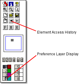
baehist.dat | BAE Element Access History | R/W | R/W | -/- | R/W | R/W | R/W | R/W |
baemacro.dat | BAE Macro Command Definitions | R/W | R/W | -/- | R/W | R/W | R/W | R/W |
scm.dat | SCM Color Tables | R/W | -/- | -/- | -/- | -/- | -/- | -/- |
ged.dat | PCB Layout Color Tables | -/- | R/W | R/W | R/W | R/W | R/W | -/- |
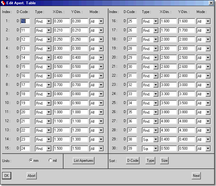
cam.dat | CAM Gerber Aperture Tables | -/- | -/- | -/- | -/- | R/W | R/W | -/- |
ced.dat | IC Design Color Tables | -/- | -/- | -/- | -/- | -/- | -/- | R/W |
ged.fnt | BAE Graphic Character Fonts | R/- | R/- | R/- | R/- | R/- | R/- | R/- |
baewin.dat | BAE Windows Position File | R/W | R/W | R/W | R/W | R/W | R/W | R/W |
baexwin.dat | BAE X11/Xwindows Position File | R/W | R/W | R/W | R/W | R/W | R/W | R/W |
bae.col | BAE Screen Color Table | R/- | R/- | R/- | R/- | R/- | R/- | R/- |
baescm.col | Schematic Editor Screen Color Table | R/- | -/- | -/- | -/- | -/- | -/- | -/- |
baeged.col | Layout Editor Screen Color Table | -/- | R/- | -/- | -/- | -/- | -/- | -/- |
baear.col | Autorouter Screen Color Table | -/- | -/- | R/- | R/- | -/- | -/- | -/- |
baecam.col | CAM Processor Screen Color Table | -/- | -/- | -/- | -/- | R/- | -/- | -/- |
baecv.col | CAM View Screen Color Table | -/- | -/- | -/- | -/- | -/- | R/- | -/- |
baeced.col | Chip Editor Screen Color Table | -/- | -/- | -/- | -/- | -/- | -/- | R/- |
baep.col | BAE Printer Color Table | R/- | R/- | R/- | R/- | R/- | R/- | R/- |
language.vdb | BAE Menu Items | R/- | R/- | R/- | R/- | R/- | R/- | R/- |
The
bsetup utility program and/or the
function from the BAE main menu of the Windows/Motif versions are used for changing the system parameters in the
bsetup.dat file. The
fontconv utility program can be applied for transferring user-defined character fonts to the
ged.fnt file. See
Bartels AutoEngineer User Manual - Chapter 7 of this manual for a description of the utility programs provided with the
Bartels AutoEngineer.
The
language.vdb file contains the
Bartels AutoEngineer menu and message texts. This file is delivered only with software configurations where the customer wants to run the BAE user interfaces with a language differing from the default German language (e.g., English).
The BAE library and
User Language directory contents are replaced when performing update installations. It is strongly recommended to backup any user-specific data from these directories before installing the BAE update and to restore the required data afterwards. The same backup and restore process should be applied to BAE programs directory files with extensions
.dat,
.def,
.fnt and
.ini when just updating from earlier BAE versions since these files can contain user-defined color tables, layer definitions, Gerber aperture tables and character fonts which are overwritten during update installations.
BAE updates can be installed to new directories. You should then copy the BAE system files with the
.dat,
.def,
.fnt and
.ini extensions from the old BAE programs directory to the BAE programs directory of the new installation to transfer all user-specific system definitions such as color tables and Gerber aperture tables to the new BAE installation.
The BAE (update) installation procedures always (re-)install the BAE system files ending on
.vdb to the BAE programs directory. These files contain version-dependent system data such as the compiled
User Language programs of the BAE software
(ulcprog.vdb) and the compiled rule definitions of the BAE software
(brules.vdb). It is therefore not necessary to run the time-consuming batch for compiling the
User Language sources provided with the BAE software or to compile the rule definition files deliverd with the BAE software. However, customer-specific
User Language programs and rule definitions developed and compiled under the previously installed BAE version must be re-compiled after performing a BAE Update Installation.
The BAE PC software for Windows, Linux, and DOS (except for BAE Demo, BAE Light and BAE Schematics) is protected by a hardlock key (dangle). You have the choice between a USB adapter for Windows and Linux or a parallel port adapter for Windows, Linux, or DOS. On Linux systems, it is also possible to use a pre-installed Ethernet card instead of a hardlock key for BAE software authorization checks.
The parellel port hardlock key must be plugged onto one of the parallel ports (LPT1, LPT2 or LPT3) of your PC. Switch off your computer before mounting the BAE parallel port module, or otherwise the hardlock key could be damaged by high voltage. If a peripheral device such as a laser printer is connected to the hardlock key, then you must always switch on the peripheral device before switching on your computer to avoid hardlock key check problems.
If your PC system has a free USB port then we recommend the USB adapter which can usually be operated more easily.
The BAE PC software provides the license files according to the available software configurations as shown in table 3. You will be asked to select the BAE software configuration (and thus the appropriate license file) when installing the BAE software. Make sure to select the BAE software configuration to be installed and/or authorized on your computer.
Table 3: BAE Software License Files
| Software Configuration | License File Name | Note |
|---|---|---|
| BAE Demo | demo.cfg | SCM and Layout; no Hardlock Key, no (CAM) output |
| BAE Schematics | schema.cfg | SCM only; no Hardlock Key |
| BAE Light | see note | SCM and Layout; no Hardlock Key, customer-specific CFG file router.cfg is provided on purchase |
| BAE Economy | economy.cfg | SCM and Layout |
| BAE Professional | autoeng.cfg | SCM and Layout |
| BAE HighEnd | highend.cfg | SCM and Layout |
| BAE Layout | layout.cfg | Layout only; required/provided only for updating from BAE Versions older than BAE Version 4.6 |
| BAE IC Design | icdesign.cfg | SCM, Layout and IC Design |
| BAE FabView | fabview.cfg | CAM/manufacturing data output; save to DDB file deactivated |
The
router.cfg license file matching the BAE software configuration authorized on your computer must be available in the BAE programs directory. I.e., to install the correct license file you can also copy the desired CFG file to
router.cfg in the BAE programs directory instead of selecting the valid BAE configuration during BAE software installation
BAE Demo software is intended for evaluation purposes only. BAE Demo cannot produce any CAM or User Language output. BAE Demo masks Layout board elements to prevent from processing with productive software configurations afterwards. I.e., the BAE user version are not able to read Demo jobs, however, we are able to convert these jobs.
The Bartels AutoEngineer software for Windows is provided on CD-ROM. I.e., you will need a CD-ROM drive if you intend to install the software.
The installation of the BAE Windows software includes the installation of the BAE programs (directory
bae), the BAE libraries (directory
baelib), the BAE
User Language sources (directory
baeulc), the BAE test jobs and examples (directory
baejobs) and the BAE online documentation (directory
baedoc), respectively. Make sure there is enough disk space available for the installation. See
chapter 2 of this documentation for information on BAE system requirements.
Under Windows, the BAE setup program for installing
BAE Demo,
BAE Schematics,
BAE Light,
BAE Economy,
BAE Professional,
BAE HighEnd,
BAE IC Design and/or
BAE FabView should start automatically after inserting the BAE CD-ROM to the CD-ROM drive. If this doesn't happen, simply start the
setupen.exe program from the CD-ROM using the
function from the Windows
menu. Please follow the instructions of the setup program.
The setup ends with the BAE software configuration. Please select the BAE configuration which is authorised for your machine (BAE Demo, BAE Schematics, BAE Light, BAE Economy, BAE Professional, BAE HighEnd, BAE IC Design or BAE FabView; see also table 3).
BAE usually closes files immediately after write procedures are completed. Depending on the type of the BAE save operation it may be necessary that BAE files are re-opened and closed subsequent to the save operations. This can lead to significant delays when saving elements in certain
Windows configurations where automatic file indexing is activated. This problem can be fixed by excluding
.ddb and
.lck files from automatic indexing using the Indexing Options in the
Windows Control Panel.
The Bartels AutoEngineer software for Windows and DOS is provided on CD-ROM. I.e., you will need a CD-ROM drive if you intend to install the software.
Four different directory path names can be chosen for installing the BAE programs (default directory path name
bae), the BAE libraries (directory
baelib), the BAE
User Language sources (directory
baeulc) and the BAE test jobs and examples (directory
baejobs), respectively. Any of these directories not yet existing are automatically created with user verification. You can manually copy the BAE online documentation (format HTML and PDF; CD-ROM directory
baedoc) to your hard disk if you wish to do so. Make sure there is enough disk space available for the installation. See
chapter 2 of this documentation for information on BAE system requirements.
For installing BAE Schematics, BAE Economy, BAE Professional, BAE HighEnd or BAE FabView under MS-DOS, the CD-ROM must be inserted to the CD-ROM drive, and the drive and directory must be set accordingly. E.g., to install the BAE software from CD-ROM drive D, insert the BAE CD-ROM to CD-ROM drive D and enter the following commands to the DOS prompt:
> D:> install
Once the install program has been started, the instructions issued on the screen should be followed carefully. First you are asked for the BAE user interface language (e.g., English, German, etc.) and for the operating system host platform (DOS, Windows NT, etc.).
The install program provides different modes for performing either new Installation or Update installations. The Update install mode is strongly recommended when just updating from earlier BAE Versions; this will prevent the install program from overwriting special BAE system and setup files ending on
.dat,
.def and
.fnt (otherwise, user-defined color tables, aperture tables, fonts, layer definitions, library access path settings and menu setups stored with these files might get lost).
After selecting the install mode, you are prompted to specify the destination directories for installing the programs, the libraries, the User Language source files and the examples and test jobs. You can exclude certain destination directories by deleting the corresponding path names. More experienced BAE users can, e.g., suppress the installation of the BAE example jobs, or re-install certain parts of the BAE software later. For security reasons, the install parameter settings are verified with user query before starting the installation process. The destination directories are automatically created on request. The install program automatically copies the BAE software files to the selected destination directories on the hard disk.
At the end of the install process, the install program asks for the licensed BAE software configuration and/or software authorization file (see table 3).
The DOS versions of the BAE software are shipped with a series of graphic device drivers. During the installation you are asked to select an appropriate BAE graphic device driver.
Table 4 lists the DOS graphic device drivers supplied with the
Bartels AutoEngineer software. Please select the graphic device driver matching the video adapter and/or graphic card installed with your computer. Or simply select standard VGA driver VGA480 if you are not sure about which driver to select. VGA480 is assumed to run on almost any PC system. The selected graphic driver file is copied to the
bae.dev file in the BAE programs directory. You can manually copy a different driver (e.g., with higher resolution) even after running the BAE DOS installation.
Table 4: BAE Graphic Device Driver for MS-DOS
| Graphic Driver | Type | Resolution | Chip Set/Manufacturer |
|---|---|---|---|
CCD480.DEV | PGA | 640x 480 | IGC (Cad Card) |
EGA350.DEV | EGA | 640x 350 | Standard |
EGA480EW.DEV | EEGA | 640x 480 | EGA Wonder |
EGA480GE.DEV | EEGA | 640x 480 | Genoa, ATI |
EGA600EW.DEV | EEGA | 800x 600 | EGA Wonder |
EGA600GE.DEV | EEGA | 800x 600 | Genoa, ATI |
EGA600PA.DEV | EEGA | 800x 600 | Paradise |
QPC1024.DEV | - | 1280x1024 | Datapath QPDM |
QPDM768.DEV | VGA | 1024x 768 | AMD QPDM |
QPDM1024.DEV | VGA | 1280x1024 | AMD QPDM |
VGA480.DEV | VGA | 640x 480 | Tseng ET3000 / ET4000 |
VGA600.DEV | VGA | 800x 600 | Tseng ET3000 / ET4000 |
VGA768.DEV | VGA | 1024x 768 | Tseng ET3000 |
TSENG768.DEV | VGA | 1024x 768 | Tseng ET4000 |
VESA600.DEV | VESA | 800x 600 | various |
VESA768.DEV | VESA | 1024x 768 | various |
MACH768.DEV | - | 1024x 768 | ATI Mach 64 |
MACH1024.DEV | - | 1280x1024 | ATI Mach 64 |
MACH1200.DEV | - | 1600x1200 | ATI Mach 64 |
MGA600.DEV | - | 800x 600 | Matrox Millenium/Mystique |
MGA768.DEV | - | 1024x 768 | Matrox Millenium/Mystique |
MGA1024.DEV | - | 1280x1024 | Matrox Millenium/Mystique |
MGA1200.DEV | - | 1600x1200 | Matrox Millenium/Mystique |
TIGA.DEV | TI | variable | Texas TMS34010 / TMS34020 |
It is strongly recommended to add the BAE programs directory path to the
PATH environment variable. Load the
autoexec.bat file to your text editor and check whether
autoexec.bat contains a
PATH statement or not. If there is already a
PATH statement defined in
autoexec.bat, then just add the following program path link to the
PATH statement (assume BAE programs directory
c:\bae):
;c:\bae
If there is no
PATH statement defined in
autoexec.bat, then insert the following
PATH statement (assume BAE programs directory
c:\bae):
PATH=c:\bae
You can also insert the following command at the end of the
autoexec.bat file to include the BAE programs directory path name with the
PATH variable:
PATH c:\bae;%path%
With the PC versions of the BAE software an environment variable called
BAETMP can be defined for optionally specifying a BAE temporary directory to avoid problems with temporary file generation on network-based PC/MS-DOS systems. To specify the BAE temporary directory the following command must be added to the
autoexec.bat file:
SET BAETMP=<dirpath>\
<dirpath> is the path name of the temporary directory (e.g.,
d:\baetmp; the backslash at the end of the path name is required).
The
config.sys file must contain the following statements:
BUFFERS=<b> FILES=<f>
The number
<b> of buffers should be at least 30, and the number
<f> of files should be at least 20.
Note that you must reboot your computer if you made any changes to the
config.sys or
autoexec.bat. Otherwise you might not be able to start BAE.
The BAE DOS software works in Protected Mode, i.e., there is no 640 Kbytes barrier.
Bartels AutoEngineer uses the
Phar Lap 386|DOS Extender, which supports
DPMI,
VCPI,
EMM386,
XMS/HIMEM,
VDISK and
INT 15h. However, in special cases (e.g., with certain third party software configurations) it might be necessary to remove conflicting memory managers. It is possible to reconfigure the BAE programs, if you wish to restrict the way in which BAE uses memory; please contact us for more detailed information in case. With EMM386 installed under MS-DOS 6.x it is strongly recommended to add the NOVCPI switch (and the NOEMS) switch to the corresponding
config.sys line since otherwise the performance for starting BAE graphic program modules will dramatically slow down.
Note that you must reboot your computer if you made any changes to
config.sys or
autoexec.bat. Otherwise you might not be able to start BAE.
The
baelinux directory on the BAE CD-ROM contains the
baelinux.tgz and
baelinus.tgz TGZ archive files with different BAE builds for Linux. Each of these TGZ files contains the directories
bin (programs and setup files),
baelib (symbol and part libraries),
baeulc (User Language source files) and
baejobs (examples and test jobs). The BAE software is supposed to run on all common Linux systems with Kernel 2.0.x (S.u.S.E. 6.0 or later, RedHat, etc.). The TGZ files
baelinhe.tgz and
baelinhs.tgz contain the binaries for
BAE HighEnd. An additional file named
baeeng.tgz including the English BAE user interface setup is also provided.
We strongly recommend that you have a look into the
readme file from the
baelinux directory of the BAE CD-ROM before installing the BAE Linux software. The
readme file contains a list of the provided BAE Linux archive files and latest information and important instructions for installing the BAE Linux software.
baelinus.tgz must be installed on Linux systems without Motif.
baelinus.tgz contains a statically linked BAE version including all system and Motif libraries (libc6/glibc, lesstif/Motif1.2) required to run BAE on any Linux Kernel 2.0.x distribution.
It is recommended to use the more efficient dynamically linked BAE version from
baelinux.tgz (linked to libc6/glibc and Motif2.0) on Linux systems where Motif is already installed. The statically linked version from
baelinus.tgz can always be used on Linux systems which fail to run the dynamically linked version.
To install the BAE Linux software, simply mount the CD-ROM drive with the BAE-CD-ROM (e.g., under
/cdrom), change to the directory where you want to install the BAE software, and unpack the appropriate archive file (e.g.,
baelinux.tgz) using the
tar command as in
> tar -xzvf /cdrom/baelinux/baelinux.tgz
The
-z option is used to filter the TGZ file through the
gzip utility. If your
tar command does not support the
-z option, simply use
gzip and
tar as in
> gzip -dv /cdrom/baelinux.tgz
To install the dynamically linked
BAE HighEnd version, simply extract the
baelinhe.tgz file after installing
baelinux.tgz. To install the statically linked
BAE HighEnd version, simply install
baelinhs.tgz after installing
baelinus.tgz.
A configuration file is provided with productive BAE Linux versions. This configuration file
(router.cfg) must be saved to the BAE program directory
(bin, see above). To activate
BAE Demo, the
demo.cfg configuration file must be copied to
router.cfg, to activate
BAE Schematics,
schema.cfg must be copied to
router.cfg (see also
table 3).
BAE is pre-configured with a German user interface. The English user interface can be activated by extracting the
baeeng.tgz archive file from the CD-ROM
baelinux directory to the destination directory.
The access rights must be set properly (i.e., execute for the programs, read access to the libraries, read/write access to the job files, all rights for the system administrator, special rights for the library manager, etc.). The user must have read access to the BAE program directory files ending on
.cfg (for authorization check) and read/write access to the files with extensions
.dat and
.fnt. The user must also have write access in the working directory to enable temporary file creation.
The Linux shell environment variable
PATH must point to the BAE programs directory to allow for BAE program call from any other directory. The
PATH variable can be set automatically through shell profile execution (shell script
.profile,
.login,
.bashrc or
.cshrc, according to Linux derivative, respectively).
The
BAE HighEnd archive files for UNIX workstation are provided in specific BAE-CD-ROM directories such as
baehp for the HP version. These archive files contain the directories
bin (programs and setup files),
baelib (symbol and part libraries),
baeulc (User Language source files) and
baejobs (examples and test jobs). An additional file named
baeeng.tgz including the English BAE user interface setup is also provided.
The
BAE HighEnd archive files for HP workstations are provided in the
baehp directory on the BAE CD-ROM. Please see the
readme file in the
baehp directory for latest information and instructions on how to install the BAE HP software.
To install the HP software, simply mount the CD-ROM drive with the BAE-CD-ROM (e.g., under
/cdrom), change to the directory where you intend to install the BAE software, and unpack the
baehp.tgz archive using the
tar command as in
> tar -xzvf /cdrom/baehp.tgz
This installs the
BAE HighEnd software with OSF/Motif interface. To activate the BAE HP software for X11, the
baehpx11.tgz file from the
baehp directory on the CD-ROM must be installed in the destination directory after installing
baehp.tgz.
A configuration file is provided with productive BAE UNIX versions. This configuration file
(router.cfg) must be saved to the BAE program directory
(bin, see above) To activate
BAE Demo, the
demo.cfg configuration file must be copied to
router.cfg, to activate
BAE Schematics,
schema.cfg must be copied to
router.cfg (see also
table 3).
BAE is pre-configured with a German user interface. The English user interface can be activated by extracting the
baeeng.tgz archive file from the CD-ROM
baelinux directory to the destination directory after installing the UNIX software.
The access rights must be set properly (i.e., execute for the programs, read access to the libraries, read/write access to the job files, all rights for the system administrator, special rights for the library manager, etc.). The user must have read access to the BAE program directory files ending on
.cfg (for authorization check) and read/write access to the files with extensions
.dat and
.fnt. The user must also have write access in the working directory to enable temporary file creation.
The UNIX shell environment variable
PATH must point to the BAE programs directory to allow for BAE program call from any other directory. The
PATH variable can be set automatically through shell profile execution (shell script
.profile,
.login,
.bashrc or
.cshrc, according to UNIX derivative, respectively).
The BAE software versions for Windows and Motif provide an interactive program for modifying the BAE system parameters. Under DOS, however, the bsetup utility must be applied as described herein.
The BAE software comes with a setup definitions file template named
stdset.def which is installed to the BAE programs directory. This file contains the following commands for setting the BAE library access paths:
SCMDEFLIBRARY("<libdir>\stdsym");
LAYDEFLIBRARY("<libdir>\laylib");
<libdir> is the path name of the BAE library directory. If the library has been installed to, e.g., the directory
c:\baelib under DOS or Windows then you should replace
<libdir> with this path name to provide correct access to the BAE symbol libraries. If the library has been installed to, e.g., the directory
/usr/bae/lib under Linux or Unix, then you should insert the following commands to the setup definitions file for providing correct access to the supplied BAE symbol libraries:
SCMDEFLIBRARY(/usr/bae/lib/stdsym); LAYDEFLIBRARY(/usr/bae/lib/laylib);
The setup definitions file can be transferred to the BAE setup file
bsetup.dat using the following
bsetup program call (assuming
stdset.def to be the name of the setup definitions file, and the BAE programs directory to be the working directory):
> bsetup stdset
The bsetup utility program is also used for defining important system parameters such as the documentary layer definitions and the menu setup. The documentary layer definitions and assignments have major impact on how manufacturing data is generated. It is strongly recommended to become familiar with the features of the bsetup utility program before using BAE for the design of real layouts. See Bartels AutoEngineer User Manual - Chapter 7.2 for details on how to use bsetup.
The BAE software installs many pre-compiled
User Language programs to the
ulcprog.vdb file of the BAE programs directory. The corresponding source files are are also provided in the
User Language directory
(baeulc). See
Bartels User Language Programmer's Guide - Chapter 4 for a complete listing and short descriptions of the BAE
User Language programs.
Some of the installed User Language programs define implicit User Language program calls for activating a modified BAE user interface with many additional functions. You can add even more functions or you can modify and/or reset the predefined menu assignments and key bindings.
Usually, it is not necessary to (re-)compile the
User Language programs delivered with the BAE software, since the compiled programs are installed to the
ulcprog.vdb file of the BAE programs directory. Nevertheless, the
User Language directory provides several batch files for automatically compiling all BAE
User Language programs. The
CPLSLL (ComPiLe with Static Link Library) batch file is recommended for compilation. The compile batch can be started in the
User Language directory
(baeulc) by entering
> cplsll
to an MS-DOS-Prompt (with the
PATH variable pointing to the BAE programs directory) or with the
> cplsll.bat
command from a Linux or UNIX shell. The compilation process might last some time according to the power of your computer.
Use the following command to start the Bartels AutoEngineer from a DOS prompt or a Linux and/or UNIX command shell:
> bae
Design file access can be simplified by starting and/or running BAE from the design and/or project files directory.
Under Windows, the
Bartels AutoEngineer can also be started by selecting the
bae.exe file using the
function from the Windows
menu. Windows also allows for application startup by double-clicking the application from Windows Explorer, and it is also possible to define an initial working directory for the application to start in. A shortcut to
bae.exe can be placed on the desktop or the Windows Start menu to provide an even more convenient method of starting up the
Bartels AutoEngineer.
When installing the BAE software under Windows, a BAE program group with shortcuts for starting the BAE main menu () and the BAE program modules (, , , , , , ) and for accessing the Bartels AutoEngineer User Manual () is added to the Windows menu.
The
option for creating a new BAE DDB file named
New BAE DDB File is included with the
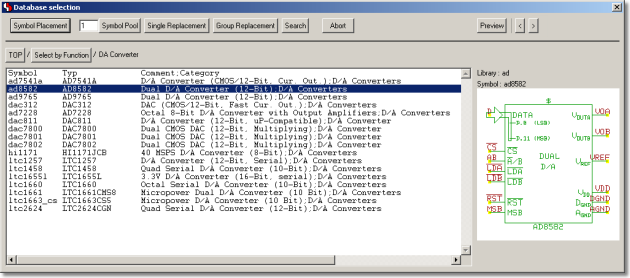
function from the Windows Desktop and Windows Explorer context menus to be activated through the right mouse button. The BAE DDB file context menus provide the
and
options for loading the selected BAE file to the
Schematic Editor and/or the
Layout Editor. Double-clicking a BAE DDB file automatically loads the DDB file's standard layout element to the
Layout Editor. The system suggests to create a new layout element if the DDB file does not yet contain a layout element with default name.
Please consult your operating system documentation for more information on how to configure applications for startup.
Environment variable references in file name specifications are automatically substituted. This allows for definitions such as
$BAELIB for the symbol library directory and combined specifications such as
$BAELIB/laylib or
$BAELIB/$STDLIB to be used for path and file name specifications in functions such as
from the
menu. The environment variables are not evaluated until they are actually referred for file access. The environment variables are stored with design files to be transferred to different computers where they can refer to machine-dependent path specifications defined through corresponding environment variables. Environment variable references are preceded with a dollar sign
($) and must be either entirely lower-case or entirely upper-case. The
~ character serves as an alias for the
$HOME variable. Undefined environment variable references are substituted with empty strings.
The environment variables listed in table 5 are evaluated for advanced configuration of BAE system file access in network installations.
Table 5: BAE System File Environment Variables
| Environment Variable | System File Default Name |
System File Contents |
|---|---|---|
BAE_CFG | router.cfg | BAE Configuration/License File |
BAE_BSETUP | bsetup.dat | BAE System Parameters |
BAE_INI | bae.ini | BAE Initialization/Startup Parameters |
BAE_BASEINI | baebase.ini | BAE Initialization/Startup Parameters (company-sepcific) |
BAE_PARLIB | baeparam.dat | BAE Parameter Settings |
BAE_MACRO | baemacro.dat | BAE Macro Commands |
BAE_HIST | baehist.dat | BAE Command History |
BAE_ULCLIB | ulcprog.vdb | BAE User Language Programs |
BAE_ULCHELP | ulchelp.vdb | BAE User Language Help Texts |
BAE_RULELIB | brules.vdb | BAE Rules Database |
BAE_LANG | language.vdb | BAE Menu String Tables (language-specific) |
BAE_FONTLIB | ged.fnt | BAE Graphic Character Fonts |
BAE_SCMLIB | scm.dat | SCM Color Tables |
BAE_GEDLIB | ged.dat | PCB Layout Color Tables |
BAE_DRCLIB | drcparam.dat | DRC Block Parameter Tables |
BAE_RUTLIB | rutparam.dat | Autorouter Parameter |
BAE_CEDLIB | ced.dat | IC Layout Color Tables |
BAE_CAMLIB | cam.dat | CAM Gerber Aperture Tables |
BAE_CAMBLIB | cambatdb.dat | CAM Batch Outpout Parameter |
BAE_EPSBLIB | epsbatdb.dat | EPS/PDF Batch Output Parameter |
BAE_DCOLLIB | bae.col | BAE Display Color Table |
BAE_PCOLLIB | baep.col | BAE Printer Color Table |
BAE_WINLIB | baewin.datbaexwin.dat | BAE Windows Position File |
BAE_CLIPB | baeclipb.dat | BAE Clipboard File |
Environment variables must specify complete paths to the corresponding system files. This feature can be used in definitions such as
set BAE_WINLIB=d:\bae\user1.dat
where access to a machine-specific Windows positions file in network installations with central BAE programs directory is established.
System files without environment variable definition are accessed from the BAE programs directory using the default system file name.
The
BAE_PROGDIR environment variable allows for the specification of an alternative system file directory.
The
ANSI_FIXED_FONT system font is used on default for displaying status line and dialog text in BAE Windows versions. Alternatively,
SYSTEM_FIXED_FONT can be selected by assigning an arbitrary value to the
BAE_OLDFONT environment variable if
ANSI_FIXED_FONT isn't suited for the configured screen/monitor resolution.
| Preface |
| Organization of this Documentation |
| Related Documentation |
| Problems, Questions, Suggestions |
| Documentation Notations |
| Documentation Conventions |
| Copyright |
| 1 | Introduction |
| 1.1 | Product Information |
| 1.1.1 | BAE Software Configurations |
| 1.1.2 | BAE System Components |
| 1.1.3 | BAE Database Structure |
| 1.1.4 | BAE Data Types and Application Concepts |
| 1.1.5 | Exchanging Data with other Systems |
| 1.2 | Operating the Bartels AutoEngineer |
| 1.2.1 | BAE Startup and BAE User Interface |
| 1.2.2 | Function Selection |
| 1.2.3 | Basic System Functions |
| 1.2.4 | Graphic Input |
| 1.2.5 | Special Remarks |
| 1.3 | BAE Design Database |
| 1.3.1 | Database Concept |
| 1.3.2 | SCM Database Hierarchy |
| 1.3.3 | Layout Database Hierarchy |
| 1.3.4 | Logical Library |
| 2 | Circuit Design / CAE |
| 2.1 | General |
| 2.1.1 | Components and Features |
| 2.1.2 | Starting the Schematic Editor |
| 2.1.3 | Schematic Editor Main Menu |
| 2.1.4 | Customized Schematic Editor User Interface |
| 2.1.5 | In-built Schematic Editor System Features |
| 2.2 | SCM Library Symbol Design |
| 2.2.1 | Creating SCM Markers |
| 2.2.2 | Creating SCM Symbols |
| 2.2.3 | Creating SCM Labels |
| 2.3 | Designing SCM Circuits |
| 2.3.1 | Creating and Editing SCM Plans |
| 2.3.2 | Symbols |
| 2.3.3 | Connections, Labels, Busses |
| 2.3.4 | Text and Graphic |
| 2.4 | Special SCM Functions |
| 2.4.1 | Virtual Symbols |
| 2.4.2 | Groups |
| 2.4.3 | Plug Pin Assignment |
| 2.4.4 | Net Attributes |
| 2.4.5 | Tag Symbols |
| 2.4.6 | Templates |
| 2.4.7 | Exiting the Schematic Editor |
| 2.5 | SCM Plot Output |
| 2.5.1 | General Plot Parameters |
| 2.5.2 | HP-GL Pen Plot |
| 2.5.3 | HP-Laser Output |
| 2.5.4 | Postscript Output |
| 2.5.5 | Generic Output under Windows |
| 2.5.6 | Bitmap Plot Output to Windows Clipboard |
| 2.6 | Hierarchical Circuit Design |
| 2.6.1 | Sub-block Circuit Drawing |
| 2.6.2 | Sub-block Reference Symbol and Logical Sub-block Reference |
| 2.6.3 | Top Level Circuit Drawing |
| 2.7 | Backannotation |
| 3 | Packager / Backannotation |
| 3.1 | General |
| 3.1.1 | Components and Features |
| 3.2 | Packager |
| 3.2.1 | Starting the Packager |
| 3.2.2 | Packager Main Menu |
| 3.2.3 | Running the Packager |
| 3.2.4 | Example |
| 3.2.5 | Messages |
| 3.3 | Backannotation |
| 3.3.1 | Starting the Backannotation |
| 3.3.2 | Running the Backannotation |
| 3.3.3 | Example |
| 3.4 | Net List Utilities |
| 3.4.1 | Importing Logical Net Lists |
| 3.4.2 | Importing Physical Net Lists |
| 3.4.3 | Exporting Net List Data |
| 3.4.4 | Net Attributes |
| 4 | PCB Design / CAD |
| 4.1 | General |
| 4.1.1 | Components and Features |
| 4.1.2 | Starting the Layout System |
| 4.1.3 | Layout Editor Main Menu |
| 4.1.4 | Customized Layout Editor User Interface |
| 4.1.5 | In-built Layout System Features |
| 4.2 | Layout Library Symbol Design |
| 4.2.1 | Creating Layout Pads |
| 4.2.2 | Creating Layout Padstacks |
| 4.2.3 | Creating Layout Parts |
| 4.3 | Designing PCB Layouts |
| 4.3.1 | Creating and Editing PCB Layouts |
| 4.3.2 | Parts, Placement |
| 4.3.3 | Text and Graphic |
| 4.3.4 | Traces, Routing |
| 4.4 | Autoplacement |
| 4.4.1 | Part Set |
| 4.4.2 | Matrix Placement |
| 4.4.3 | Initial Placement |
| 4.4.4 | Placement Optimization |
| 4.5 | Autorouter |
| 4.5.1 | Starting the Autorouter |
| 4.5.2 | Autorouter Main Menu |
| 4.5.3 | Customized Autorouter User Interface |
| 4.5.4 | In-built Autorouter System Features |
| 4.5.5 | Autorouter Options |
| 4.5.6 | Autorouter Control |
| 4.5.7 | Autorouter Strategy |
| 4.5.8 | Autorouter Functions |
| 4.5.9 | Using the Autorouter |
| 4.6 | Special Layout Features |
| 4.6.1 | Batch Design Rule Check, Report |
| 4.6.2 | Color Setup, Color Tables, Pick Preference Layer |
| 4.6.3 | Layout Net List Changes |
| 4.6.4 | SCM Changes, Redesign |
| 4.6.5 | Defining and Editing Power Layers |
| 4.6.6 | Autorouter Via Keepout Areas |
| 4.6.7 | Area Mirror Mode |
| 4.6.8 | Automatic Copper Fill |
| 4.6.9 | Library Update |
| 4.6.10 | Back Net List |
| 4.6.11 | Blind and Buried Vias |
| 4.6.12 | Exiting the Layout System |
| 4.7 | CAM Processor |
| 4.7.1 | Starting the CAM Processor |
| 4.7.2 | CAM Processor Main Menu |
| 4.7.3 | Customized CAM Processor User Interface |
| 4.7.4 | In-built CAM Processor System Features |
| 4.7.5 | Plot Parameters |
| 4.7.6 | Power Layers |
| 4.7.7 | HP-GL Output |
| 4.7.8 | HP Laser Output |
| 4.7.9 | Postscript Output |
| 4.7.10 | Windows Generic Output |
| 4.7.11 | Bitmap Plot Output to Windows Clipboard |
| 4.7.12 | Gerber Photoplot |
| 4.7.13 | Drill Data |
| 4.7.14 | Insertion Data |
| 4.8 | CAM View |
| 4.8.1 | Starting the CAM View Module |
| 4.8.2 | CAM View Main Menu |
| 4.8.3 | Customized CAM View User Interface |
| 4.8.4 | In-built CAM View System Features |
| 4.8.5 | Processing Gerber Data |
| 4.8.6 | Processing Drilling and Milling Data |
| 4.8.7 | Retrieving Layouts from Gerber Data |
| 5 | IC/ASIC Design |
| 5.1 | General |
| 5.1.1 | Components and Features |
| 5.1.2 | IC Design System Startup |
| 5.1.3 | Chip Editor Main Menu |
| 5.1.4 | Chip Editor User Interface |
| 5.1.5 | Chip Editor System Features |
| 5.2 | IC Cell Library |
| 5.2.1 | IC Pin Definitions |
| 5.2.2 | IC Cell Definitions |
| 5.3 | IC Mask Layout |
| 5.3.1 | Creating and Editing Chip Layouts |
| 5.3.2 | Cell Makros, Placement |
| 5.3.3 | Text and Graphic |
| 5.3.4 | Traces, Routing |
| 5.4 | Cell Placer |
| 5.4.1 | Cell Placer Startup |
| 5.4.2 | Cell Placer Main Menu |
| 5.4.3 | Cell Placer System Features |
| 5.4.4 | Cell Placer Options |
| 5.4.5 | Cell Placer Control |
| 5.4.6 | Cell Placer Functions |
| 5.5 | Cell Router |
| 5.5.1 | Cell Router Startup |
| 5.5.2 | Cell Router Main Menu |
| 5.5.3 | Cell Router System Features |
| 5.5.4 | Cell Router Options |
| 5.5.5 | Cell Router Control |
| 5.5.6 | Cell Router Strategy |
| 5.5.7 | Cell Router Functions |
| 5.6 | IC Design Data Import and Export |
| 5.6.1 | GDS Data Import and Output |
| 5.6.2 | CIF Data Import and Output |
| 6 | Neural Rule System |
| 6.1 | General |
| 6.2 | Rule Definition |
| 6.2.1 | Bartels Rule Specification Language |
| 6.2.2 | Bartels Rule System Compiler |
| 6.3 | Rule System Applications |
| 6.3.1 | Circuit Design Rule System Applications |
| 6.3.2 | PCB Design Rule System Applications |
| 6.4 | Rule System Predicates |
| 6.4.1 | Circuit Design Rule System Predicates |
| 6.4.2 | PCB Design Rule System Predicates |
| 7 | Utilities |
| 7.1 | BAEHELP |
| 7.2 | BAESETUP, BSETUP |
| 7.3 | BICSET (IC Design) |
| 7.4 | BLDRING (IC Design) |
| 7.5 | CONCONV |
| 7.6 | COPYDDB |
| 7.7 | FONTCONV |
| 7.8 | FONTEXTR |
| 7.9 | INSTALL |
| 7.10 | LISTDDB |
| 7.11 | LOGLIB |
| 7.12 | NETCONV |
| 7.13 | REDASC |
| 7.14 | RULECOMP |
| 7.15 | ULC - User Language Compiler |
| 7.16 | User Language Interpreter |
| 7.17 | USERLIST |
| 7.18 | VALCONV |
| Tables |
| 2-1 | Special BAE Attributes |
| 4-1 | Autorouter Grids |
| 4-2 | Autorouter Strategy Parameters |
| 4-3 | Pick Preference Layer Color Tables and Short Layer Names |
| 4-4 | Gerber Aperture Table "standard" |
| 5-1 | Cell Router Strategy Parameters |
| Figures |
| 1-1 | Bartels AutoEngineer System Flow Diagram |
| 1-2 | BAE Pulldown Menu User Interface |
| 1-3 | BAE Side Menu User Interface |
| 1-4 | SCM Database Hierarchy |
| 1-5 | Layout Database Hierarchy |
| 1-6 | Part Data Sheet with Loglib Definition |
| 2-1 | SCM Library Symbols |
| 2-2 | SCM Symbol CD4081 |
| 2-3 | SCM Library Access |
| 2-4 | SCM Sheet with Symbols |
| 2-5 | SCM Sheet with Symbols, Connections |
| 2-6 | SCM Sheet with Symbols, Connections, Labels |
| 2-7 | SCM Bus Connections |
| 2-8 | SCM Sheet Demo/Sheet1 |
| 2-9 | SCM Sheet Demo/Sheet2 |
| 2-10 | Hierarchical Circuit Design; Sub-Block SCM Sheet "BLOCK" |
| 2-11 | Hierarchical Circuit Design; Block Symbol "DFF" with Loglib Definition |
| 2-12 | Hierarchical Circuit Design; Top Level SCM Sheet |
| 3-1 | Design Flow Packager - Backannotation |
| 3-2 | Part CD4081 Data Sheet with Loglib Definition |
| 3-3 | Net Attribute Definitions |
| 4-1 | Layout Library Symbols |
| 4-2 | Layout with Board Outline and Plot Markers |
| 4-3 | Layout Library Access |
| 4-4 | Layout with Part Placement |
| 4-5 | Routing with or without Via Offset |
| 4-6 | Routing Traces Ongrid/Offgrid |
| 4-7 | Layout after Autorouting |
| 4-8 | Automatic Copper Fill Complexity |
| 4-9 | Layout with Filled Copper Areas |
| 4-10 | CAM Mirror Modes |
| 4-11 | CAM Power Layer Isolation |
The Bartels AutoEngineer® - User Manual describes in detail how to use the Bartels AutoEngineer CAE/CAD/CAM design system. The following main topics are covered by this manual:
The reader of this documentation should be familiar with the use of his operating system and a text editor for generating ASCII files on his system.
Kindly note the Copyright before making use of the information provided with this documentation or applying the herein described products. The reader should also be familiar with the Notations and Conventions used throughout this documentation.
| Chapter 1 | describes the Bartels AutoEngineer system architecture, provides general operating instructions and introduces the design database. |
| Chapter 2 | describes in detail how to use the Schematic Editor for creating SCM library symbols and designing circuits. |
| Chapter 3 | describes how to use the Packager program module and the function for performing forward and backward annotation of net list data. |
| Chapter 4 | describes in detail how to use the Layout Editor, the Autoplacement functions and the Autorouter for creating layout library symbols and designing PCB layouts, and how to use the CAM Processor and CAM View modules for creating and processing CAM output and manufacturing data for the PCB production. |
| Chapter 5 | describes how to use the Chip Editor, the Cell Placer, and the Cell Router for the interactive and/or automatic design of IC mask layouts. |
| Chapter 6 | describes the Bartels Neural Rule System, i.e., how to define neural rules with the Bartels Rule Specification Language, how to compile rule specification source files using the Bartels Rule System Compiler and how to apply neural rules throughout the Bartels AutoEngineer design process. |
| Chapter 7 | describes the utility programs of the Bartels AutoEngineer software. |
The Bartels AutoEngineer® - Installation Guide describes the Bartels AutoEngineer configurations and system requirements and provides detailed Bartels AutoEngineer installation instructions for all supported hardware and software platforms.
The Bartels AutoEngineer® - Symbol and Part Libraries documentation contains detailed information about the symbol and part libraries provided with the Bartels AutoEngineer CAE/CAD/CAM design system.
The Bartels User Language - Programmer's Guide describes how to use the Bartels User Language in Bartels AutoEngineer, i.e., how it is integrated to the Bartels AutoEngineer EDA system and how it can be applied. The following main topics are covered by this manual:
We appreciate comments from the people who use our system. In particular we are thankful for suggestions on how to improve the Bartels AutoEngineer and/or the Bartels User Language by introducing new or improving existing functions. Please do not hesitate to contact Bartels Support if you have questions or problems related to the use of the Bartels AutoEngineer. Check the Bartels Website at http://www.bartels.de for our address.
The reader should be familiar with the following notations used throughout the Bartels AutoEngineer documentation:
| Mouse | pointing device (mouse, trackball, etc.) to be used for moving the menu and graphic cursors as well as for selecting functions |
|---|---|
| Info Field | menu field on the right top of the screen for displaying system status messages |
| Main Menu | function menu permanently available in the upper right screen area used for selecting a subordinate function menu |
| Menu | function menu in the lower right screen area currently selected from main menu |
| Submenu | subordinate function menu in the lower right screen area activated intermediately whilst using another menu function |
| Graphic Workarea | workarea for graphic interaction in the upper left screen area |
| Status Line | lower left screen line used for displaying system status messages and for performing interactive user queries |
| Menu Cursor | rectangle-shaped cursor for selecting a menu function |
| Graphic Cursor | cross-shaped cursor in the graphic workarea (crosshairs) |
| Menu Prompt | user query in the status line |
| Popup Menu | menu optionally displayed on top of the graphic workarea for selecting function-specific objects or for activating menu-specific functions |
| Button | selectable popup menu entry for choosing a certain menu element or for activating a menu-specific function |
| Select Function | move menu cursor to a function of the currently active function menu |
| Activate | hitting the mouse button |
| Pick | select an object to be manipulated using the graphic cursor |
| Place | move an element to a certain position in the graphic workarea |
| Select | select an element to be manipulated or a function to be executed by pressing the mouse button |
| Confirm | confirm the execution of a function verified by user query |
The following acronyms are used throughout the Bartels AutoEngineer documentation:
| BAE | acronym for identifying the Bartels AutoEngineer EDA software |
|---|---|
| BAEICD | acronym for the Bartels AutoEngineer IC/ASIC design system optionally included with workstation-based BAE configurations |
| SCM | acronym for the Schematic Editor program module of the Bartels AutoEngineer circuit design system |
| GED | acronym for the graphical PCB Layout Editor program module of the Bartels AutoEngineer PCB design system |
| AP | acronym for the Autoplacement program module of the Bartels AutoEngineer PCB design system |
| AR | acronym for the Autorouter program module of the Bartels AutoEngineer PCB design system |
| NAR | acronym for the advanced Neural Autorouter program module of the Bartels AutoEngineer PCB design system |
| CAM | acronym for the CAM Processor program module of the Bartels AutoEngineer PCB design system |
| CV | acronym for the CAM View program module of the Bartels AutoEngineer PCB design system |
| CED | acronym for the Chip Editor program module of the Bartels AutoEngineer IC/ASIC design system |
| CP | acronym for the Cell Placement program module of the Bartels AutoEngineer IC/ASIC design system |
| CR | acronym for the Cell Router program module of the Bartels AutoEngineer IC/ASIC design system |
| UL | acronym for the Bartels User Language programming language |
| ULC | acronym for the Bartels User Language Compiler |
| ULI | acronym for the Bartels User Language Interpreter |
Unless otherwise mentioned, the following symbolic conventions are used throughout the Bartels AutoEngineer documentation:
Lineprint | Lineprint font represents text output generated by the system. |
| Boldface | Boldfaced words or characters in format or command descriptions represent topic definitions or syntactic terminals, i.e., commands or keywords to be inserted directly. |
| Emphasize | Emphasized text is used for optical accentuation. |
| " " | Double quotes denote names and/or path names or enclose characters and/or character sequences directly to be inserted. |
| [ ] | Square brackets enclose optional items in format or command descriptions. |
| { } | Braces enclose a list of items in format or command description, from which one has to be chosen. |
| | | A vertical bar separates items in a list of choices. |
| < > | Angle brackets enclose the logical name of a key on the keyboard. In format or command descriptions, angle brackets enclose values to be supplied. |
> | Boldfaced greater signs in lineprint font are used for denoting prompts on operating system level. |
| ... | Horizontal ellipsis points indicate either optional repetition of the preceding element in format or command descriptions or absence of irrelevant parts of a figure or example. |
| : | Vertical ellipsis points indicate absence of irrelevant parts of a figure, an example or a format or command description. |
| Any Mouse Button (MB) | |
| Left Mouse Button (LMB) | |
| Middle Mouse Button (MMB) | |
| Right Mouse Button (RMB) | |
| Keyboard (input) - Return/Enter key (CR) | |
| a b ... | Keyboard (input) - standard key(s) |
| F1 F2 ... | Keyboard (input) - function key(s) |
filename | File or directory path name. |
keyword | Topic definitions or syntactic terminals, i.e., commands or keywords to be inserted directly. |
| BAE/system status or error message display. | |
| Bartels AutoEngineer menu. | |
| Bartels AutoEngineer menu function. | |
| Bartels AutoEngineer menu option. | |
| Bartels AutoEngineer (popup) menu button. | |
| ul.ulh | (Hypertext link to) Bartels User Language include file. |
| ulprog | (Hypertext link to) Bartels User Language program description. |
| ul.ulc | (Hypertext link to) Bartels User Language program source file. |
| ul_function | (Hypertext link to) Bartels User Language system function description. |
| UL_INDEX | (Hypertext link to) Bartels User Language index type description. |
| utilprog | (Hypertext link to) Bartels AutoEngineer utility program description. |
| new feature | New features which are made available with regular (weekly) software updates/builds are highlighted in the online documentation. |
The character sequences mentioned above may regain original meaning when used in programming languages, interpreter languages, specification languages, syntax description languages, etc.
The information contained in the Bartels AutoEngineer publications as well as the products and/or programs described therein are subject to change without notice and should not be construed as a commitment by Bartels System.
Although Bartels System has gone to great effort to verify the integrity of the information provided with the Bartels AutoEngineer publications, these publications could contain technical inaccuracies or typographical errors. Bartels System shall not be liable for errors contained therein or for incidental consequential damages in connection with the furnishing, performance or use of this material. Bartels System appreciates readers' and/or users' comments in order to improve these publications and/or the products described therein. Changes are periodically made to the information therein. These changes will be incorporated in new editions of the Bartels AutoEngineer publications.
All rights reserved. No part of the Bartels AutoEngineer publications may be reproduced, stored in a retrieval system, translated, transcribed or transmitted, in any form or by any means manual, electric, electronic, electromagnetic, mechanical, chemical, optical or otherwise without prior express written permission from Bartels System.
Bartels AutoEngineer®, Bartels Router® and Bartels Autorouter® are registered trademarks of Bartels System. Bartels User Language™ and Bartels Neural Router™ are trademarks of Bartels System. All other products or services mentioned in this publication are identified by the trademarks or service marks of their respective companies or organizations.
This chapter describes the Bartels AutoEngineer system architecture, provides general operating instructions and introduces the design database.
| 1.1 | Product Information |
| 1.1.1 | BAE Software Configurations |
| 1.1.2 | BAE System Components |
| 1.1.3 | BAE Database Structure |
| 1.1.4 | BAE Data Types and Application Concepts |
| 1.1.5 | Exchanging Data with other Systems |
| 1.2 | Operating the Bartels AutoEngineer |
| 1.2.1 | BAE Startup and BAE User Interface |
| 1.2.2 | Function Selection |
| 1.2.3 | Basic System Functions |
| 1.2.4 | Graphic Input |
| 1.2.5 | Special Remarks |
| 1.3 | BAE Design Database |
| 1.3.1 | Database Concept |
| 1.3.2 | SCM Database Hierarchy |
| 1.3.3 | Layout Database Hierarchy |
| 1.3.4 | Logical Library |
| Figures |
| 1-1 | Bartels AutoEngineer System Flow Diagram |
| 1-2 | BAE Pulldown Menu User Interface |
| 1-3 | BAE Side Menu User Interface |
| 1-4 | SCM Database Hierarchy |
| 1-5 | Layout Database Hierarchy |
| 1-6 | Part Data Sheet with Loglib Definition |
Bartels AutoEngineer (BAE) is a fully integrated EDA software system with powerful CAE/CAD/CAM program modules for circuit design, PCB (printed circuit board) layout and IC/ASIC design. The system is based on the famous Bartels AutoEngineer which has been incorporated in most leading PCB layout systems throughout the world, setting new industrial standards of autorouting success and dramatically reducing the requirement for manual routing.
The following Bartels AutoEngineer software configurations are available:
All BAE software configurations are provided with the same user interfaces and support different languages (English, German, etc.). Bartels AutoEngineer features binary-compatible design data management on different host platforms, i.e., BAE design data can be transferred "as-is" between all supported hardware and/or operating system platforms (Windows, Linux/Unix, DOS, etc.).
Bartels AutoEngineer Professional is the basic BAE software configuration described in this manual. BAE Professional is available for PCs with Windows, Linux or DOS operating systems. The following components are included with the BAE Professional software:
BAE Schematics, the Schematic Editor of BAE Professional is freely available and can be operated in stand-alone mode. Demo software configurations of BAE Professional (BAE Demo, fully-featured except for data output) are available free of charge for test and evaluation purposes.
Bartels AutoEngineer Light is available for PCs with Windows, Linux or DOS operating systems. BAE Light is a shareware price-level BAE configuration for educational purposes and/or semi-professional users. BAE Light provides full BAE Professional functionality, however, with the following restrictions:
Bartels AutoEngineer Economy (formerly known as Bartels AutoEngineer Educate/Entry) is available for PCs with Windows, Linux or DOS operating systems. BAE Economy is a low-price BAE configuration for educational purposes and/or small business users. BAE Economy has full BAE Professional functionality, however, with the following limitations:
Bartels AutoEngineer HighEnd is available on workstations as well as on Windows and Linux PC platforms. BAE HighEnd utilizes special operating system characteristics (multi-tasking, multi-windowing, virtual memory management, etc.) to implement advanced features and functions such as:
BAE HighEnd is data-compatible to BAE Professional in both directions; requested data transformations are automatically applied during element load procedures.
BAE HighEnd can be upgraded to a fully featured ASIC design system. Bartels AutoEngineer IC Design (BAEICD) is a complete CAD/CAM system for the physical design of integrated circuits (gate arrays, standard cells, custom ICs and/or ASICs). BAEICD consists of a series of system components such as IC Mask Editor, IC Autoplacement, IC Autorouter and IC DRC (Design Rule Check). GDS-II and CIF standard interfaces are provided for converting foreign data and/or producing CAM output (mask data, bonding data, etc.). The BAEICD CAM tools include a module for displaying CIF data in order to perform visual CAM output checks. Net list data is usually transferred by the BAE Packager after defining the circuitry with BAE Schematics, which provides features for hierarchical circuit design. Alternative solutions for importing foreign/third-party netlist data/formats can be provided on request.
Bartels AutoEngineer FabView is a low-cost PCB layout viewer with manufacturing data output functions. BAE FabView is intended for PCB manufacturing departments and service providers who only have to produce manufacturing data and print/plot outputs but don't have to edit layouts. BAE FabView can be used together with BAE Professional and/or BAE HighEnd. BAE FabView provides the same functionality, however, the functions for saving layout design changes to BAE project files are deactivated.
Bartels AutoEngineer basically consists of a Schematic Editor, a Layout Editor with Autoplacement and Autorouter and a CAM Processor with a supplemental module for viewing and processing CAM data. A Packager program module and a function are provided for automatic forward and backward annotation of net list data from the schematics to the layout and vice versa. BAE supports all phases of modern computer-aided PCB design including schematic capture, physical PCB layout featuring powerful Autoplacement and Autorouting facilities and, finally, generating all of the required manufacturing data and documentation. See figure 1-1 for a design flow diagram of the Bartels AutoEngineer.
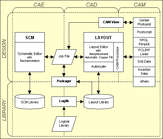
Figure 1-1: Bartels AutoEngineer System Flow Diagram
CAD systems must process and/or manage huge amounts of design data. Therefore, the internal database structure of a CAx system is an important criteria for estimating the power of the system. The Bartels AutoEngineer is based on especially designed, homogeneous, object-oriented, hierarchical database structures featuring optimized B-tree search algorithms for fast database object access. Variable keyword lengths and generic data structures guarantee that neither redundancies nor system limits are imposed by the software. The system is only limited by the available amount of main memory. I.e., the software imposes no restrictions with regard to the number of symbols and/or sheets of a schematic circuit, number of parts placed on a layout board, number of pins defined on a part, number of traces routed on a layout, etc.
All BAE CAD data is organized and managed in a fully integrated database with a common binary data format for all supported hardware platforms. Each CAD object is dynamically constructed of its individual components. Library elements from lower database hierarchy levels (e.g., parts on a PCB) are copied (with all sub-elements) from the currently selected library to the currently processed design file when they are first requested, e.g., for placement on the upper hierarchy level. This results in a job-specific library in the design file. Subsequent requests for the same element will then refer to the element already copied to the current design file, i.e., the job-specific library elements are accessed with highest priority. This concept prevents any library and/or design file modification from unintentionally affecting another design and/or library file. AutoEngineer objects can be composed of sub-elements from different libraries. A BAE library file can be build up by accessing one or more other libraries. Even a particular design file can be used as library for another design file. Library definitions such as pin or part symbols can be modified at any stage. Any such modification is automatically reflected up the library hierarchy.
All data relating to one particular design is kept in a single file thus avoiding the confusion of multiple file structures. This so-called design database (DDB) file contains different element types relating to schematic, layout, net lists, part lists, etc. all of which go together to make a complete design. This concept supports highly efficient data management features for the creation, modification, backup, update and redesign of design files and library files alike.
The BAE system is comfortable to use with simple instructions aided by convenient user control over menu and mouse. The menus and manuals are available in different languages (German, English, etc.). The standard BAE user interface is the same on all hardware platforms. With the BAE windows versions the user can optionally use the windows-like BAE user interface with pull-down menus. It is easy to learn how to work with the system since the functions for creating and modifying objects are quite similar for all object types of the different library hierarchy levels. The BAE software also provides most powerful tools for customizing the BAE user interface with menu assignments and online key binding for calling user-defined functions.
The floating point database used throughout the Bartels AutoEngineer has many advantages. Firstly it means that there are virtually no grid limits to designs. Any pad shape, component shape, track width, board size or shape, copper area size or shape, etc. can easily be generated. Secondly it means that online design rule checking (DRC) of copper and track clearances and void areas run at all time during layout providing instant indication of errors. Floating point calculation also means that all geometry is stored extremely accurately. The system can either accept metric or imperial numeric input which is automatically converted to floating point information.
A powerful function is provided to ensure data security and to allow for comfortable evaluation of different design modifications. Real-time graphic interaction (re-display at zoom and pan, moving graphic elements, etc.) is self-evident, as well as graphical built-in features such as definable color tables or display, query and highlight of elements, connections and errors, etc.
A pool is used for managing data in main memory. This also controls basic features such as the display functions or . Complex operations such as moving parts are extremely fast since all data is converted in real-time from internal hierarchical representation to vector/polygon-oriented display mode. Fast workspace and clipping window checks are performed on graphical elements to guarantee high-speed re-display. These functions are implemented with internal programming interfaces to support different graphic controllers. Large objects like wiring paths and areas are stored in compressed internal format to avoid redundant memory usage. An entire trace path located on a particular layer occupies just one pool element, as well as e.g., a 84 pin PGA on subsequent placement (only the connectivity is stored separately, the geometry refers to the symbol instantiated with the first placement request). The maximum number of pool elements on 32 bit computer systems is 2^31=2,147,483,648. I.e., the pool on non-virtual systems is limited rather by available memory and/or pointer address space than by the complexity of the design.
All coordinate and angle values are stored in internal 32 bit IEEE floating point format. Online operations requiring higher precision are performed with double (64 bit) precision. Each element can be placed with arbitrary coordinates at any rotation angle. Skillful linkage to the hierarchical database system avoids performance disadvantage even on slow floating point processors. References to named elements (such as pins or parts) are always stored as strings. Identical strings are linked together to one file entry. I.e., naming of e.g., plug or PGA pins such as
c32 is easily possible without creating redundancies.
Bartels AutoEngineer provides tools for importing different ASCII net list formats, placement data and routing data (via Gerber format). Functions for generating insertion data, drill data, Gerber photoplots, Postscript output, HP-GL pen plots and HP-Laser (PCL) output are integrated to the CAM Processor of the Bartels AutoEngineer. A special programming language (Bartels User Language) can be applied for implementing user-specific programs for importing and/or exporting almost any data such as part lists, net lists, geometry data, drill data, insertion data, milling data, etc. in freely definable formats.
After successful installation with correct path setting the Bartels AutoEngineer can be started from any directory, but it is recommended to start BAE from the directory where the projects and/or the design files should be generated (this considerably simplifies job file access).
You can start the Bartels AutoEngineer from your projects directory by typing
> bae
to the operating system prompt (for testing the software you can use the BAEJOBS directory created during the software installation).
Within Windows, the
Bartels AutoEngineer can be started by selecting the
bae.exe file using the
function from the Program Manager Files menu. Windows- and X11/Motif-based operating systems also allow for application startup by clicking the icon of the corresponding program file. Startup icons also allow for the definition of the directory to be entered on default when starting the corresponding application, i.e., BAE can be configured to be started from the BAE jobs directory or from any user-specific BAE project directory. A reference of the BAE startup icon can be included with the operating system launchpad and/or
menu to provide an even more convenient method of starting up the
Bartels AutoEngineer. The default BAE setup links the
.ddb file name extension to the BAE application in such a way that the
Layout Editor automatically starts and loads the default project layout when double-clicking a
.ddb file. Right-clicking the
.ddb file activates a context menu which provides the choice of starting either the
Layout Editor with the default layout or the
Schematic Editor with the last modified SCM sheet. Please consult also your operating system manual for more details on how to configure applications for startup.
On default, the Windows and Motif versions of the Bartels AutoEngineer are configured with pull-down menus. This user interface is vertically organized and consists of the main menu bar on top, the graphic work area in the middle and an info line followed by the status and input line at the bottom. Function menus are activated in pull-down mode when selecting the corresponding main menu item. Under Windows, the submenu from the menu provides the function for activating an Explorer-style tree view function menu which can be displayed either to the left or to the right of the graphic workarea.
After starting the BAE, the Bartels company logo and/or a copyright note is displayed in the graphic workarea and the status line displays the program version and/or the user names.
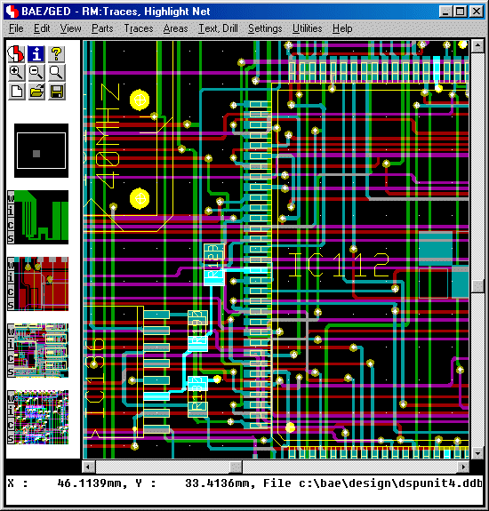
Figure 1-2: BAE Pulldown Menu User Interface
If the message appears, then check for correct software authorization (i.e., hardlock key and appropriate license file installation; see the Bartels AutoEngineer® Installation Guide for more details).
The Bartels AutoEngineer can optionally be operated with a side menu user interface. The graphic display of the side menu user interface is divided into different areas as shown in the figure below. It consists of the graphic workarea, an input and/or status line below the graphic workarea and an info field and function menus on the right side.
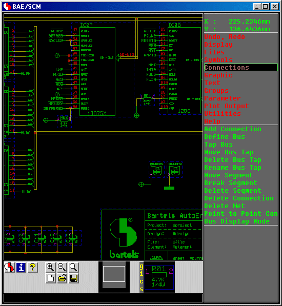
Figure 1-3: BAE Side Menu User Interface
Under Windows and Motif, the BAE user interface can be selected and/or configured through the dialog from the BAE main menu. Alternatively, the bsetup can be used to select the BAE user interface (see chapter 7.2 for more details).
If the BAE DOS version fails to load the graphic display, then check for correct BAE graphic device driver installation (see the Bartels AutoEngineer® Installation Guide for more details).
The pull-down user interfaces of the BAE Windows/Motif versions provide a permanently displayed main menu bar at the top. Main menu selections usually activate a more particular pull-down function menu. A particular menu function is selected by moving the mouse to the corresponding menu item and pressing the left mouse button. The menu item strings usually contain underlined characters to denote hotkeys for fast activation of the corresponding menu and/or function. I.e., main menu items can also be activated and/or selected by pressing the denoted character together with the Alt key, and pull-down menu functions can be activated and/or selected by simply pressing the denoted hotkey. The middle mouse button provides instant access to the menu, i.e., pressing the middle mouse button is possible at any time and from any other function and provides fast access to frequently required display functions such as zoom and pan, changing color setup, setting the input and/or display grid, etc. Pressing the middle mouse button will also cause a status line display of the current file and element name if no other menu function is currently active. The middle mouse button interaction can also be simulated by simultaneously holding down both the left and the right mouse button. I.e., it is possible to activate the online display menu even if only a two-button mouse is installed and/or configured. Any currently active menu function can be immediately aborted and/or canceled by pressing the escape key ESC (ASCII code 27; abort hotkey).
To call the Layout Editor function , activate the function menu by selecting the main menu item , then select the function from the pull-down menu. The left mouse button provides fast access to the previously processed function, i.e., pressing the left mouse button re-activates the same function as was processed with the previous operation. The function currently assigned to the left mouse button is displayed in the BAE window title bar. Right-clicking the toolbar button H provides quick access to the 16 last called menu functions.
The Windows pull-down menus as well as the menu functions are context-sensitive, i.e., they are only selectable when currently applicable, otherwise they are faded-out ("ghost" menus). Menu separator lines are used throughout the Windows pull-down menu system to separate function groups.
The Windows and Motif versions provide context menus with element-specific functions which can be activated by right-clicking elements in the graphic workarea. The p (properties) key activates a dialog for displaying and/or modifying the properties of the element at the current mouse position.
For certain functions such as file name selection, the BAE Windows/Motif user interfaces provide Windows- and/or Motif-specific dialogs or popup menus instead of BAE standard popup menus. Scrollbars are displayed with BAE Windows and Motif workarea text popups to provide unrestricted access to the contents of lengthy listings and/or protocols.
The cursor/arrow keys can be used under Windows and Motif to scroll the BAE display by half of its dimension in the key-specific direction. The Page Up and Page Down keys scroll the display up or down by its full height. In combination with the Shift key, Page Up and Page Down scroll to the left and right, respectively. Scrolling is limited by the boundaries of the currently loaded element. The Home and End keys can be used to jump immediately to the upper or lower element boundary. In combination with the Shift key, Home and End scroll to the left and right element boundary, respectively.
Under Window and Motif, the mouse wheel can be used to move the current view port upwards or downwards by half its size. In combination with the Shift key, the mouse wheel moves the view port to the left or right, respectively. With the left mouse key pressed, the mouse wheel can be used to zoom in or out.
BAE Windows and Motif sessions can be finished using the standard function from the application window system menu or by clicking the Windows close button of the application window. To prevent from accidentally discarding design changes, these exit procedures might require user confirmation with an option for saving the currently processed element.
When ending a BAE Windows or Motif session, the dimensions and positions of the BAE application and dialog windows are automatically saved to a configuration file with the name
baewin.dat or
baexwin.dat in the BAE programs directory. The next BAE session automatically loads and restores the windows dimensions and positions from the configuration file.
BAE HighEnd stores window positions not only with BAE module names but also with current session window numbers, thus allowing for multiple project windows of to be restored with the next BAE session. This is very useful when using
BAE HighEnd with multi-monitor systems.
The menu area on the right side of the BAE standard user interface is divided into a main menu and a standard function menu. Selections are allowed in both of these menus. The permanently displayed main menu is used for activating the more particular function menu displayed below the main menu. Each function of the same process can be reached with only one mouse interaction and each other function can be reached with a maximum of only two mouse interactions.
Within the menu fields of the BAE standard user interface the green menu cursor can be moved with the mouse. A particular menu function is selected by moving the mouse to that function and by pressing either the left or the right mouse button. To call the function the Layout Editor, simply activate the function menu by selecting the main menu item, then select the function from the menu. Once the function is completed, it can be re-activated by simply pressing the left or right mouse button or you can select any other function from the still active menu. If you e.g., want to change to the function, just choose the main menu item and select the function from the menu.
After selecting a particular function, either another menu is displayed or the user is prompted for keyboard input via the input line or graphic input via the graphic cursor is expected in the graphic workarea. Any messages displayed in the status line are displayed as long as they are relevant. Input prompts (e.g., for coordinate and/or length/width inputs) and error messages contain the name of the processed element if available. Graphic cursor inputs are accompanied by a status line message indicating the expected type of input. The color of the menu cursor changes to red to designate that the BAE system is waiting for some user input. The middle mouse button provides instant access to the menu, i.e., pressing the middle mouse button is possible at any time and from any other function and provides fast access to frequently required display functions such as zoom and pan, changing color setups, setting the input and/or display grid, etc. Pressing the middle mouse button will also cause a status line display of the current file and element name if no other menu function is currently active. The middle mouse button interaction can also be simulated by simultaneously holding down both the left and the right mouse button. It is possible to activate the online display menu even if only a two-button mouse is installed and/or configured. Any currently active menu function can be immediately aborted and/or canceled by pressing the escape key ESC (ASCII code 27; abort hotkey).
A series of functions are implemented with popup menus, where the object to be processed can be selected by mouse-pick. These popup menus simplify the use of basic data and file management functions such as , , , , etc. With each popup menu, the input line is enabled for manual element name input via keyboard and special popup menu buttons such as (for canceling the current function), (for scrolling down the popup menu selections list) or (for scrolling up the popup menu selection list) are usually provided.
The dialogs and/or popup menus for net list part and net name selections support
?prefix input for scrolling the list display to the specified name prefix. A name prefix specification such as
?r4 scrolls to the first name starting with
?r4 or, if no such name exists, to the next name thereafter. Part and net list scrolling positions specified through name prefices are saved for subsequent name queries.
The menu color settings of the BAE standard user interface can be changed with the bsetup utility program. Please note that suitable menu colors might achieve considerable ergonomic advantages such as better recognition of the currently active menu and/or function. See chapter 7.2 of this manual for a description of the bsetup utility program.
Bartels User Language provides system functions for performing key programming and defining menu assignments and/or toolbars. It is possible to define key bindings such as key r for activating User Language program rotate. New or existing menus and/or menu entries can be (re-)configured to support special User Language program calls. These features provide a most powerful tool for configuring the menus of the AutoEngineer modules. It is a good idea to utilize the User Language startup programs for performing automatic key binding and menu setup. Even dynamic changes to the AutoEngineer user interface can be supported with special User Language programs for performing online key and menu programming. Note that due to these features your currently configured AutoEngineer user interface might provide special user-specific add-on functions which are not described in this documentation. See the Bartels User Language Programmer's Guide for a detailed description of the Bartels User Language and its implicit program call features.
Facilities for cascading submenu definitions are implemented for the BAE Windows and Motif pulldown user interfaces. Submenus can be attached to menu items. The uifsetup User Language program is designed to configure cascading menus for the BAE Windows/Motif modules. This allows for easy submenu function location (and activation) without having to activate (and probably cancel) submenus. The function repeat facility provided through the right mouse button also supports cascading menus. This simplifies repeated submenu function calls significantly.
A series of Windows/Motif dialogs are implemented such as display and general parameter settings in all BAE modules, SCM plot parameters settings, Autoplacement and copper fill parameter settings, Autorouter routing batch setup and routing options, strategy and control parameter settings and CAM Processor control plot, Gerber photoplot and drilling data output parameter settings. These dialogs can be activated through the bae_callmenu User Language function. The uifsetup User Language program is designed to provide menu functions for activating the dialogs in the BAE Windows/Motif modules.
A message system is integrated to BAE HighEnd to enable advanced communication between different AutoEngineer program modules. The BAE HighEnd Shell (i.e., the BAE HighEnd main menu) is used as message exchange switchboard. Hence the BAE Shell knows only about its own descendants, i.e., descendant BAE tasks must be started using appropriate BAE HighEnd functions ( from the BAE Shell, from the menus of the Schematic Editor or the Layout Editor or switch between different program modules of the current BAE session). With BAE HighEnd, several views of a project, e.g., overview and zoomed details can be displayed at the same time. The use of multitasking and pipes also enables simultaneous processing of schematics and layout. I.e., BAE HighEnd supports advanced cross-module features such as simultaneous and/or global net highlight for schematic plans and layout of the same design (project specific multi-windowing/multitasking, cross-probing).
The middle mouse button is used to call the menu whilst performing a graphical manipulation like component placement or routing. This allows for the change of display options such as zoom scale, grids, colors, etc. without canceling the current operation. After the display choice has been made you will automatically return to the graphical manipulation that was in progress before the middle mouse button was pressed. I.e., the global placement of a part can be performed with the complete layout displayed, whilst the final placement of that still picked part can be accomplished in a more detailed zoom window.
The colors for displaying the design objects can be changed with the
function from the
menu. At overlaps of different elements the resulting mixed color is displayed. The highlight color is also mixed with the color of the element to be marked, thus resulting in a brighter display of that element. The
function from the
menu is used to saved the current color table definition to a system file (whichever appropriate for the current program module). Once a color table has been saved, it can be reloaded at any time using the
function from either the
menu. Special color tables (e.g., for library edit, for finding unroutes, etc.) can be defined and reloaded on request. The default color table to be loaded after the startup of a particular BAE program module is the one named
standard.
Changing some item-specific color is accomplished by selecting the desired display item using the left mouse button and then selecting the desired color button from the function. In the layout system, provides a feature for fast display item fade-out/fade-in. Activating and/or deactivating some item-specific display is accomplished by selecting the desired display item entry with the right mouse button which works as a toggle between fade-out and fade-in. The system won't loose information on currently defined colors of faded-out display items; strike-through color buttons are used for notifying currently faded-out display items.
The floating point database used throughout Bartels AutoEngineer allows to specify arbitrary placement coordinates. Input grids and angles can be released and/or locked at any time from throigh the menu which can be activated with the middle mouse button. Nevertheless, the choice of a suitable input grid has fundamental meaning for design processes such as Autorouting or manufacturing data generation. Placing parts in 1/10" or 1/20" grids with just exceptional deviation (e.g., for plugs) will considerably facilitate both manual routing as well as Autorouting. Trace corners at 45 degree angle steps are recommended for better manufacturing results unless deviation is indispensable.
The cursor/arrow keys can be used together with the Shift key to move the mouse/graphic cursor to the next input grid point in direction of the arrow key. Shift together with Enter selects the current input grid coordinate (as if a corner was selected with the left mouse key) and a subsequent Enter key input terminates the definition of a point list as if was selected through the right mouse key. This allows for on-grid traces or polygons to be created through the keyboard only.
BAE uses a conventional coordinate system which always references the current position of the origin. It can be useful to reposition the origin to make absolute coordinate references easier - even for one command. A special submenu can be activated with the right mouse button when manipulating objects in the graphic workarea (placing/moving elements, creating polygons, etc.). This submenu provides functions for specifying absolute or relative coordinate values.
accepts an absolute coordinate value referring to the origin of the currently loaded element.
accepts a coordinate value relative to the previous input coordinate value (e.g., when drawing polygons). Floating point coordinates can be specified, where fractional parts of corresponding numeric values must follow the decimal point
(.). Coordinate values are interpreted either in mm units or in inch units, depending on whichever default input units are defined with the
USERUNITS setup parameter (see also
chapter 7.2 of this manual for a description on how to define
USERUNITS with the
bsetup utility program). Non-default metric input is forced by attaching
mm to the input value. Non-default imperial input is forced by attaching the double quote character
" to the input value. Metric and imperial values can be mixed arbitrarily. Precision throughout the whole system is ensured with BAE's floating point database based on common internal system units. The system also support polar coordinate input through the
Polar Coordinates button and subsequent radius and angle value prompts. Attaching an
R to the angle value will force the system to interpret the value in Radians instead of (default) Degree units.
All numeric input fields of the BAE dialogs support simple arithmetic expressions with add, subtract, multiply and divide operators and round brackets. An equal sign at the end of the expression causes the system to calculate and display the result immediately in the input field. Otherwise, the expression is evaluated when the dialog box closes successfully. This allows for, e.g., a
to be carried out through a
dialog with the relative coordinates added to the absolute coordinates using the
+ operator.
Most of the BAE functions require an element (e.g., SCM sheet, layout board, library symbol, etc.) to be loaded. A particular element is specified by element type, file name and element name. The element name is the unique name of the element in the selected design database (DDB) file. The process of loading an element is activated after specifying the element name. There are two methods for specifying file and element names. Either select the file and/or element name with popup menu and mouse-pick or perform direct keyboard input by typing in the name to the corresponding input line prompt. The file name of the currently loaded element is used if you select the
popup menu button or if you type in an empty string (by pressing the return key
![]() ) to the file name prompt. DDB file name queries in the
Schematic Editor and the layout system also accept
) to the file name prompt. DDB file name queries in the
Schematic Editor and the layout system also accept
! input for selecting the SCM and/or the layout standard library defined through the BAE setup (see also
chapter 7.2).
Please do not forget to save the currently loaded element before exiting from the program or loading or creating another element. The system activates a popup menu with options for discarding and/or saving changes to prevent from unintentionally discarding design changes in cases where an unsaved element is about to be unloaded.
When loading a BAE DDB file element, the element's modification time is retrieved. This modification time is checked against the current time when saving the element. User confirmation request is issued if the DDB file element appears to have been changed, thus providing advanced support and security for BAE network installations where different users might simultaneously modify the same DDB file element.
With the BAE standard user interface, an intelligent popup menu for optionally selecting directories is integrated to the file name query functions. This feature can be activated by selecting the
button from the currently active file selection popup menu. The
bsetup command
PROJROOTDIR (see
chapter 7.2) can be used to define the root of the directory tree to be displayed for directory name selection; on default the current directory (relative path name
.) will be used. The background color for the directory selection popup menus can be defined using the
POPMFILL option of the
FRAMECOLOR bsetup command (see also
chapter 7.2). Directories with subdirectories are displayed in hierarchically arranged graphic frames. Directories without subdirectories are displayed with their name only. Directories including files with extension
.ddb (DDB files) are marked by appending a plus sign
(+) to the end of the directory name. The
button of the directory selection menus is used to scroll in the directory selection menu. The
button can be used to switch to a more detailed display of the selected directory; the
button can be used to switch back to the directory survey. Selecting the
button will cancel the file name query. An error message such as
is issued if there are no subdirectories available in the directory defined by
PROJROOTDIR. After selecting a valid directory, the file name query is reactivated with the file names of the selected directory provided for selection.
With the Windows and Motif user interfaces of the BAE software, Windows- and/or Motif-specific popup menus for file name selection with directory navigation and listboxes for element name queries are automatically provided.
The file and element name queries provide default names (current project file name, selected library, current element name, etc.) if at all possible and/or appropriate. The functions from the menus can only be applied to DDB file elements which are not referenced by any other element from the same DDB file.
A feature for optionally performing automatic design data saving is implemented with the
Schematic Editor, the
Layout Editor and the
Neural Router. This feature is controlled with the
function from the
menus. The
function requires a positive integer input designating the autosave time interval in minutes. On zero or dash
(-) input the automatic save facility will be deactivated. With
activated, the system automatically saves the currently processed element to a backup file at the specified time intervals.
However, to prevent
from overwriting backup files in situations where an element is only loaded for viewing/checking purposes, the backup is only performed if the currently loaded element was modified during the autosave interval.
The name of the backup file is automatically derived from the current job file name and has the extension
.bak. Autosaved elements can be restored using features such as the
function from the
menu or the
copyddb utility program.
Important design and operational parameters such as autosave time interval, name of the currently loaded color table, input and display grid, angle and grid lock, coordinate display mode, standard placement angle and mirror mode, standard text size, library access paths, plot file names, standard trace widths, function class, airline display mode, placement matrix, copper fill parameters, etc. are automatically saved with the currently processed layout board and/or SCM sheet or with the processed library hierarchy level (part, padstack, pad, SCM symbol, etc.). When loading an element, the corresponding parameter set is automatically loaded as well, thus providing a convenient way of setting up a default design environment suitable for processing the selected database and/or design element.
At the creation of a new element the system will prompt for the element boundary. The element boundary corresponds with the workspace on a paper for manual drawing, i.e., the element boundary defines the overall size of the data element and must not be confused with the board outline or any other artwork drawing. It is utilized for preventing the system from creating or placing objects somewhere outside in hidden infinite regions, i.e., nothing can be drawn or placed outside the workspace (which otherwise would be possible because of the floating point coordinates supported by the system). The element boundary can be enlarged or reduced with the and functions from the menu. Note that workspaces larger than necessary are worsening performance at screen redraw, zoom, pan and certain other functions. It is a good idea to shrink each element's workspace; element workspaces can easily be enlarged at any time lateron.
The Bartels AutoEngineer group functions allow powerful manipulation in both the Schematic Editor and the Layout Editor. The group functions are featuring set principles. Groups can be defined either by selecting individual items or by defining the area around the items that you want to select. Choice of item types and the ability to de-select with the same technique makes it easy to define a group. Group-selected elements are marked by highlight, and these are the only objects to be affected by subsequent group functions. Groups can be moved, copied, deleted or saved and loaded. When saved they are stored as an element of the same type as that from which the group was selected and can be accessed by the appropriate editor. When saved a group origin must be defined which becomes the origin of the new element and is used as the reference point for group load commands. Group facilities can be used for a variety of tasks such as replicating circuitry and/or tracking, saving and loading standard SCM blocks or PCB templates, stealing from existing and proven designs, etc.
With the and functions from the menu, the Bartels AutoEngineer can be used without fear of causing damage. Previously executed commands can be reversed or undone using and then reprocessed with . This ensures data security and provides a powerful feature for validating different design options.
On default, the system supports twenty steps. The dialog from the BAE main menu provides options for increasing the number of supported steps for the Schematic Editor and/or the Layout Editor to up to one hundred.
Input to the BAE graphic workarea is performed with the graphic cursor and the mouse. The most important graphical interactions are pick and place. Pick means selecting an item which is already placed in the graphic workarea. Place means placing a new item to the graphic workarea. A pick function is often followed immediately by a place function, e.g., when moving a part.
The left mouse button is used both for selecting an element (pick) for further manipulations and for selecting the current graphic cursor position for place operations such as placing a selected part or defining the next corner point of the trace or polygon to be currently created. The right mouse button is used either for canceling pick operations or for activating a submenu with special options. This options submenu provides choices appropriate for the current graphic operation. These include important functions such as setting rotation angles and mirroring during placement, specifying direct coordinate input (, ) during placement or polygon point definition, performing layer changes or setting trace widths during manual routing, generating arcs whilst drawing lines or defining areas, defining text sizes whilst moving texts, finishing a manually routed trace or a polygon definition, etc.
Each area and line (or trace) in the Bartels AutoEngineer is defined as a polygon. The corresponding menus for the creation and manipulation of such items are in the Schematic Editor and (or ) in the Layout Editor. BAE supports different polygon types such as graphic area, graphic line and dotted line in schematics or passive copper area, active copper area, keepout area, documentary area, documentary line, copper fill workarea and trace in the layout system. Each polygon can consist of an arbitrary number of polygon points and arc segments. An arc segment is created by defining the arc segment start point, then choose the requested orientation with submenu function or and select the arc center point, and finally define the arc segment end point. When finishing the polygon definition with the submenu function, the system distinguishes between area and line definitions, and the last polygon point is connected to the first point when creating an area. No area can contain intercrossing segments because otherwise basic operations like checking polygon intersection for clearances and short circuits, polygon filling features, area size changes, etc. would not be possible. The polygons created by the Bartels AutoEngineer are not just simple line drawings but intelligent arbitrary shaped polygons. The system is fully capable of applying complex operations on these polygons such as move, copy, enlarge, shrink the polygon, move, delete, insert polygon corner points and/or polygon segments, perform automatic copper fill and/or hatching, perform design rule checking, etc.
Redundant polygon points should be avoided because they might cause trouble, e.g., when generating certain CAM data. In this context, the definition of full circles in BAE is worthwhile to be mentioned here especially. A full circle is created by defining a point on the circle, then choose either or from the submenu and select the circle center point and finish the definition with the submenu function. Alternatively, the c key can be pressed to set the circle center point, and then a second point can be selected to set the circle radius.
The preceding paragraphs explained the basic concepts of operating the BAE design system. Now you can become more familiar with the BAE system functions by working through the examples provided with this manual. You should also have a close look at the bsetup utility program and the AutoEngineer database concept before starting the design of real projects since the user-definable setup parameters and database conventions have most considerable inpact on the design process and the possibilities of manufacturing data output.
Some of the more complex BAE functions such as loading or moving groups might require some CPU time. Within the Windows version of the BAE software the mouse cursor will change to a sand clock symbol to indicate that the system is waiting for the completion of some function. Within the BAE standard user interfaces the menu cursor changes its color (to red) to indicate that the system is currently busy. This is also true for operations where the system expects some user input in the graphic workarea or via keyboard input. After the completion of a particular function the menu bar color of the BAE standard user interface changes back (to green) to indicate that the user can activate another function. More time-consuming functions such as batch design rule check or connectivity generation will even report the percentage of completeness for better information. It is strongly recommended to wait for each BAE function to be successfully completed, because interrupting a function by e.g., resetting your computer might cause irreparable damage of design data.
Kindly note the importance of backing up your design data when working on real projects. Every now and then we are asked to restore damaged design data on faulty hard disks. A hard disk can suffer a genuine loss of data by headcrash or other hardware defects, and we are not able to help if not even a simple backup has been performed. A regular backup of your project (DDB) files is strongly recommended. You can also use the function from the menu (see above) for activating the automatic design data backup feature.
Before generating and releasing manufacturing data, you should always perform a complete design rule check using the function from the menu of the Layout Editor. Subsequently, the DRC result should be examined with the function. Never start the CAM data output if clearance violations or short circuits are indicated since otherwise you might produce useless PCBs in almost any case. Also ensure that the CAM process does not cause any troubles such as overdraw errors. Apply CAM View on generated Gerber data for visual checks. Furthermore it is recommended to perform extensive tests on prototypes before starting any mass production. You should be able to achieve good project and production results with the Bartels AutoEngineer if you follow these instructions.
The key feature of the Bartels AutoEngineer design system is its powerful design database. It is a genuine object-oriented database since this has been proven to be optimum for accessing and processing the complex data types of different size used throughout the AutoEngineer. Powerful search algorithms are implemented for fast access to the database objects, and a high-sophisticated library management program provides simultaneous access to different symbol libraries. The user is able to define both standard libraries and job-specific libraries for particular projects. These libraries can be stored with the job and completely and/or partially transferred to or from a central standard system library.
Each database entry is assigned to a predefined database class and is identified by an element name which is unique in this database class. Each element contains the data defined on that element, i.e., graphic items, texts, pin positions and pin designators on SCM and/or layout symbols, etc. Higher level database entries can refer elements of subordinate database hierarchy levels. Such a reference consists of the element placement coordinates, a name referring the subordinate database symbol, and the name of the placed element if it is a named reference. E.g., a layout contains the named references of the part symbols placed on the layout, the parts contain the named references to the padstack symbols defined on the part, and the padstacks contain the unnamed references to the pad symbols used on these padstack. All references of a certain element are transparent throughout the corresponding DDB file. When loading or copying that element, all pertinent references are automatically be loaded and/or copied.
All database classes are subject to general file and database management functions. I.e., the Schematic Editor is suitable for creating and manipulating SCM plans as well as for editing SCM library elements such as symbols, labels, and pins. The same is true for the Layout Editor concerning the creation and manipulation of layouts, parts, padstacks and pads. All functions are automatically adjusted to the current environment and database hierarchy level. Corresponding menus and functions from the Schematic Editor and the Layout Editor are quite similar. I.e., the SCM function is equivalent to the Layout Editor function, and the Layout Editor function is used for placing parts on layouts, for placing padstacks on parts or for placing pads on padstacks, whichever is appropriate for the currently loaded element. This concept creates far-reaching analogies for the processing of objects of different database classes and makes it fairly easy to learn how to use the BAE design system.
All program modules of the
Bartels AutoEngineer are working with the same database and file format. This file format is called Design DataBase (DDB) format. The
.ddb file name extension is used for indicating the DDB file type. All of the design data relating to one particular design is kept in a single DDB file, thus avoiding the confusion of multiple file structures. This DDB file contains different element types relating to schematics, PCB layout, net list data, library symbols, parameter settings, etc. all of which go together to make a complete design. This concept introduces most efficient data management features for creation, modification, backup, update and redesign of both design and library files. The BAE library files including SCM and layout symbols, logical library entries, etc. are also prepared in DDB format.
AutoEngineer objects can be composed of sub-elements from different libraries. A library or design file can be build up by accessing one or more other libraries, and even a particular design file can be used as library for another design.
Each element is constructed dynamically during load. E.g., when loading a layout element to the Layout Editor, first the data pertinent to the layout is read and then the referenced part elements are loaded from the same project file; with each part element the referenced padstack symbols are loaded, etc. This dynamic load process presupposes that all required elements are available in the project file. The system will automatically check on missing library symbols, and requested elements not available are copied and loaded from the currently selected library. With this process, consistent construction of job-specific libraries without the need of storing redundant library elements in a job file is always ensured. This concept introduces considerable advantages with regard to project archiving or independence from master library availability. Modifications in a certain DDB file are reflected up the library hierarchy levels of that file without affecting any other DDB file, and the functions for deleting library elements prevent from erasing DDB file elements which are referenced by other elements from the same DDB file. I.e., data consistency throughout any particular DDB file is automatically ensured. Nevertheless, BAE provides powerful features for transferring library data between different DDB files such as the function from the menu which can be used for correlating job-specific libraries with master library contents.
A further advantage of the BAE database concept is the possibility of adapting project-specific libraries to special manufacturing processes. For this purpose, so-called technology parts containing special pin and/or padstack definitions can be defined in technology-specific library files. With a technology part a complete set of technology-dependent pin definitions can be defined (e.g., SMD pad definitions for a special SMT soldering process or annular pad shapes for manual drilling). Functions such as or can be utilized for copying a technology part to a certain project file in order to include pin and/or pad definitions requested for a special manufacturing process.
The function from the menu is used in both the Schematic Editor and the Layout Editor for creating new BAE library (and design) elements. After specifying the new element library hierarchy level the user is asked for the name of the DDB file where the element is to be stored, the name of the element to be created and the element boundaries. Subsequently, the element is defined by placing elements from subordinate library hierarchy levels and by creating additional objects such as documentary graphic, text, drill holes, contact areas, keepout areas, etc. (whichever is permissible on the currently edited library hierarchy level).
Bartels User Language provides SQL (Structured Query Language) functions for maintaining relational databases, thus introducing powerful software tools for programming database management systems. These tools e.g., can be utilized for integrating a component database to the Bartels AutoEngineer to perform stock and cost expenditure analysis on different variants of a layout including facilities for choosing components with controlled case selection and part value assignment. This however is just one example from the wide range of possible database applications; utilizing database systems could be worthwhile also in the fields of project and version management, address list maintenance, production planning and inventory control, supplier and customer registers management, etc. See the Bartels User Language Programmer's Guide for a detailed description of Bartels User Language and its integrated SQL functions.
Figure 1-4 shows the structure of the database hierarchy supported throughout the Bartels AutoEngineer SCM system.
The SCM sheet level is the top hierarchy level of the BAE SCM design system database. On SCM sheet level, the circuit diagram of a particular design is defined by generating SCM sheets, placing symbols and creating connections and busses. Labels, bus taps and module ports can be placed for defining signal names and for connecting different sheets. Graphic and text can be created for documentation purposes such as creating SCM sheet frames, including commentary text, etc. Part and net attribute values can be assigned for setting variable component properties and/or for controlling subsequent design processes such as Autorouting or CAM data output.
On SCM symbol level the schematic part symbols are defined (and stored to SCM symbol libraries). A schematic symbol is usually defined by placing elements from the subordinate marker level, thus creating the logical pins of the corresponding part. Graphic and text can be created on symbol level for including symbol outlines, part name references, attribute definitions, commentary text, etc.
Special symbols for signal naming purposes are defined on SCM label level. These symbols can be utilized on SCM sheet level for assigning signal names or signal levels to connections and/or busses, for tapping busses, for connecting different SCM sheets, etc.
Pin symbols are created by defining a contact area on SCM marker level. Marker symbols can be placed on SCM symbol and/or label level to determine the positions of the corresponding part pins. The contact area is required for connecting the corresponding pin on SCM sheet level. A reference designator text can be defined on marker level for showing pin names on symbol level. Marker symbols with a normal graphic area instead of a contact area can be utilized on SCM sheet level for creating and displaying T-connections.
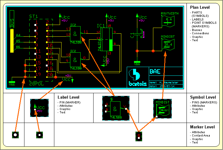
Figure 1-4: SCM Database Hierarchy
Figure 1-5 shows the structure of the database hierarchy supported throughout the Bartels AutoEngineer PCB design system.
The layout level is the top hierarchy level of the BAE PCB design system database. On layout level the PCB contour is defined, the parts (from the subordinate layout part level) are placed, keepout areas, power planes and copper areas are defined, the traces are routed, and, finally, the CAM output is generated. Drawing items and text can be created on layout level for such things as plot registration markers, measurement, project identification, etc.
On layout part level the layout part symbols (i.e., the part package types) are defined (and stored to a layout part library). A particular layout part symbol is usually defined by placing elements from the subordinate padstack level in order to define the types and positions of the physical pins of the corresponding part. Traces and vias (e.g., for printed inductors), keepout areas (for part clearance check, defining via keepout areas, etc.), copper areas, drawing information (component outline on insertion plan) and text (for part name reference, insertion data pick point, attribute value display, etc.) can be created optionally.
On layout padstack level the layout pin symbols and vias are defined by placing symbols from the subordinate pad level. Each pad can be assigned to a signal and/or documentary layer thus designating contact areas for the routing or defining pad shapes for solder resist, SMD masks, etc. A drill hole and drill plan info can be created optionally for the definition of vias or drilled pins. Keepout areas can be utilized for controlling the pin contact mode. Documentary lines or areas can serve as pin designators on the silk screen or insertion plan and reference texts can be used for displaying pin names on part and/or layout level.
On layout pad level the pad shapes (i.e., the pin contact areas) are defined by creating passive copper areas. Different pad symbols can be assigned to different layers on a single padstack symbol thus defining a particular layout pin type.
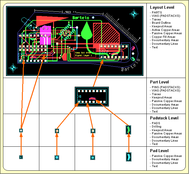
Figure 1-5: Layout Database Hierarchy
The Bartels AutoEngineer logical library provides the link between the SCM library and the layout library. The logical library contains information about the assignment of SCM symbols to layout packages including gate definitions and pin mapping, pin/gate swap rules, predefined power supply pins, fixed part attributes, etc. All these definitions can be entered to an ASCII file to be subsequently transferred to a BAE DDB file using the loglib utility program (see chapter 7.11 of this manual for a description of the loglib utility program). The logical library definitions are required by the Packager for compiling logical net list data created by the Schematic Editor to physical net list data which can be processed by the BAE layout system (see chapter 3.2 of this manual for a more detailed description of the BAE Packager). During a Packager run, the logical library entries are checked against the corresponding layout library symbols for ensuring correct pin mappings. Please note that the Packager can evaluate only one library file at the same time, i.e., both the required logical library data and the requested layout library data must be stored to the same DDB file.
Figure 1-6 shows a loglib file example containing a logical library part definition according to the manufacturer's part data sheet.
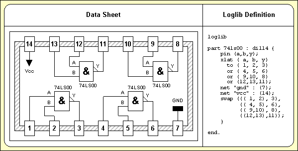
Figure 1-6: Part Data Sheet with Loglib Definition
The following sequence of operations is recommended for the definition of a new part:
Once the above tasks are completed, the new SCM symbol can be used for circuit drawing, the Packager is able to assign this SCM symbol to the correct layout package, and the corresponding layout part is available for placement in the layout. For less-experienced users it is a good idea to use a test file for new definitions, and to perform a Packager test run before releasing new library parts for real projects. This should prevent from unintentionally introducing erroneous library definitions to BAE library and/or project files.
This chapter describes in detail how to use the Schematic Editor for creating SCM library symbols and designing circuits. The examples presented with this chapter introduce the concepts and advanced features of the BAE Schematic Editor in a logical sequence and will take the user through the design and modification of library symbols and a circuit drawing which will be subject to further processing in the subsequent chapters. The reader should work through this chapter without missing any sections to gain full understanding of the BAE Schematic Editor. Once a command has been used and/or explained, the operator is assumed to have understood its function and be able to perform it again. Subsequent instructions containing this command will be less verbose for easier reading and more speedy learning.
| 2.1 | General |
| 2.1.1 | Components and Features |
| 2.1.2 | Starting the Schematic Editor |
| 2.1.3 | Schematic Editor Main Menu |
| 2.1.4 | Customized Schematic Editor User Interface |
| 2.1.5 | In-built Schematic Editor System Features |
| 2.2 | SCM Library Symbol Design |
| 2.2.1 | Creating SCM Markers |
| 2.2.2 | Creating SCM Symbols |
| 2.2.3 | Creating SCM Labels |
| 2.3 | Designing SCM Circuits |
| 2.3.1 | Creating and Editing SCM Plans |
| 2.3.2 | Symbols |
| 2.3.3 | Connections, Labels, Busses |
| 2.3.4 | Text and Graphic |
| 2.4 | Special SCM Functions |
| 2.4.1 | Virtual Symbols |
| 2.4.2 | Groups |
| 2.4.3 | Plug Pin Assignment |
| 2.4.4 | Net Attributes |
| 2.4.5 | Tag Symbols |
| 2.4.6 | Templates |
| 2.4.7 | Exiting the Schematic Editor |
| 2.5 | SCM Plot Output |
| 2.5.1 | General Plot Parameters |
| 2.5.2 | HP-GL Pen Plot |
| 2.5.3 | HP-Laser Output |
| 2.5.4 | Postscript Output |
| 2.5.5 | Generic Output under Windows |
| 2.5.6 | Bitmap Plot Output to Windows Clipboard |
| 2.6 | Hierarchical Circuit Design |
| 2.6.1 | Sub-block Circuit Drawing |
| 2.6.2 | Sub-block Reference Symbol and Logical Sub-block Reference |
| 2.6.3 | Top Level Circuit Drawing |
| 2.7 | Backannotation |
| Tables |
| 2-1 | Special BAE Attributes |
| Figures |
| 2-1 | SCM Library Symbols |
| 2-2 | SCM Symbol CD4081 |
| 2-3 | SCM Library Access |
| 2-4 | SCM Sheet with Symbols |
| 2-5 | SCM Sheet with Symbols, Connections |
| 2-6 | SCM Sheet with Symbols, Connections, Labels |
| 2-7 | SCM Bus Connections |
| 2-8 | SCM Sheet Demo/Sheet1 |
| 2-9 | SCM Sheet Demo/Sheet2 |
| 2-10 | Hierarchical Circuit Design; Sub-Block SCM Sheet "BLOCK" |
| 2-11 | Hierarchical Circuit Design; Block Symbol "DFF" with Loglib Definition |
| 2-12 | Hierarchical Circuit Design; Top Level SCM Sheet |
The schematic capture system of the Bartels AutoEngineer essentially consists of an interactive Schematic Editor with integrated SCM symbol editor and integrated and the Packager program module for converting logical into physical netlists ("Forward Annotation"). The following sections of this manual describe in detail how to use the Schematic Editor for creating and editing SCM symbols and schematic circuitry.
When working with a Schematic Editor, the user expects the net list to agree exactly with the circuit drawing. The Schematic Editor of the Bartels AutoEngineer is not just a simple drawing program but is also capable of instantly controlling and correlating the net list data with the circuit diagram. Every single net list change results in an incremental update of the net list data. Reliability on correct net list data recognition is achieved with an internally managed list of changes which is also used for controlling the facilities. BAE utilizes contact areas for indicating unconnected pins. Contact areas will automatically disappear with correct connections to the corresponding pins. This feature provides most useful graphical utility for controlling net list data whilst editing circuit diagrams. The system is also able to recognize T-shaped connections, and a junction point marker is automatically placed for the indication of T-connections.
With Bartels AutoEngineer, SCM symbols can be freely defined without restrictions referring to symbol size, symbol drawing information, number of pins on a part symbol, etc. The user can utilize but is not necessarily restricted to some standard. A series of extensive SCM symbol libraries is delivered with the Bartels AutoEngineer. The symbol placement functions provide features such as rotating the symbol at any angle, symbol mirroring, specifying arbitrary placement coordinates, etc.
Signal names can be freely defined. Inverted signal names are displayed with a line on top of the corresponding text. User-definable label symbols are automatically loaded when referencing the corresponding signal names, e.g., a ground label symbol can be defined for indicating ground connections.
Bartels AutoEngineer provides full capability of checking connectivity with busses, bus tapping, sub-bus definitions, bus naming, etc. Both numerical and arbitrary alphanumerical names can be used for bus signals. Incremental net list data update is included with all bus definition features. The SCM library even supports bus synthesis on part level, thus providing highest flexibility at the creation of symbols of any complexity.
The BAE system supports hierarchical circuit design. It is possible to define SCM block circuit diagrams which then can be referenced from other SCM plans using special block symbols. For correct net list data management a distinction between global and local signals is possible.
The facilities allow to use the Schematic Editor without fear of causing damage. Up to twenty commands can be reversed or undone by applying the function and then reprocessed with the function. ensures data security and provides a powerful feature for estimating design alternatives.
With the Bartels User Language integrated to the Schematic Editor the user is able to implement enhanced CAE functions and macros, user-specific post processors, report and test functions, etc. User Language programs can be called by applying the function from the menu or by pressing a key on the keyboard (hot key).
The Schematic Editor provides a series of enhanced features such as group functions, arbitrary attribute definitions and part and/or net attribute value settings, automatic part naming with definable part name patterns, virtual symbols for company logos or circuit legends, net highlight, automatic reconnection at symbol movement, etc. Net list modifications introduced to the layout such as pin/gate swaps or part name changes are reflected back to the SCM automatically by applying Backannotation.
It is recommended to start the Bartels AutoEngineer from the directory where the design files should be generated since this considerably simplifies job file access. If you intend to process the examples provided with this manual it is recommended to move to the BAE examples directory installed with the BAE software. The Schematic Editor can be called from the Bartels AutoEngineer main shell. Start the BAE shell by typing the following command to the operating system prompt:
> bae
The AutoEngineer comes up with the Bartels logo and the following menu (the function is only available under Windows/Motif; the and menu items are available only with special software configurations such as BAE HighEnd or BAE IC Design):
| Schematic |
| Layout |
| [ IC-Design ] |
| Packager |
| CAM-View |
| [ Setup ] |
| [ Next Task ] |
| Exit BAE |
Move the menu cursor to the menu item and confirm this choice by pressing the left mouse button:
| Schematic |
Now the Schematic Editor program module is loaded and the SCM menu will be activated. If this fails to happen then check your BAE software installation (see the Bartels AutoEngineer® Installation Guide for details on how to perform a correct installation).
The Schematic Editor standard/sidemenu user interface provides a menu area on the right side, consisting of the main menu on top and the currently active menu below that main menu. After entering the Schematic Editor, the menu is active and the menu cursor points to the function.
The Windows and Motif versions of the
Schematic Editor can optionally be operated with a pull-down menu user interface providing a horizontally arranged main menu bar on top. The
WINMENUMODE command of the
bsetup utility program is used to switch between
SIDEMENU and
PULLDOWN Windows/Motif menu configurations (see
chapter 7.2 for more details).
The following main menu is always available whilst processing SCM elements with the Schematic Editor:
| Undo, Redo |
| Display |
| Files |
| Symbols |
| Connections |
| Graphic |
| Text |
| Groups |
| Parameter |
| Plot Output |
| Utilities |
The functions provided with the menu allow you to use the Schematic Editor without fear of causing damage. Up to twenty commands can be reversed or undone using and then reprocessed with the . This is true even for complex processing such as group functions or User Language program execution. ensures data security and provides a powerful feature for estimating design alternatives.
The or menu can either be activated by selecting the corresponding main menu item or by pressing the middle mouse button. Activation through the middle mouse button is even possible whilst performing a graphical manipulation such as placing or moving an object. The or menu provides useful functions for changing display options such as zoom window, zoom scale, input and/or display grids, grid and/or angle lock, color settings, etc. The or menu also contains advanced display functions such as and .
The menu provides functions for creating, loading, saving, copying, replacing and deleting DDB elements. The menu also allows to load and/or store color tables or to call important database management functions such as listing DDB file contents and performing library update.
On SCM sheet level, the functions from the menu are used for placing, moving and deleting symbols, labels, and module ports, for assigning attribute values and for displaying symbol logic definitions from the Logical Library. On symbol and label level, the functions from the menu are used for placing, moving and deleting pins (i.e., marker symbols), and for defining name patterns for the automatic part naming facility.
The menu is used on SCM sheet level to create the logical net list by generating and/or manipulating connections and busses.
The menu is used on any SCM hierarchy level for creating, moving, copying and deleting graphic items such as lines and areas.
The menu is used on any SCM hierarchy level for defining, changing, moving and deleting text.
The menu provides functions for selecting elements to group, for moving, copying, deleting, saving and loading groups, and for replacing symbols in a group.
The menu provides functions for selecting the SCM library, setting the origin of the currently loaded element, defining the element boundaries, selecting the pin symbol and the T-connection marker, defining the SCM sheet hierarchy for hierarchical circuit designs, and activating the automatic design data backup feature.
The menu provides the functions for generating plot output in HP-GL (Hewlett Packard Graphics Language), HP Laser (PCL, Printer Command Language) or Postscript format.
The menu provides functions for exiting BAE, returning to the BAE main shell, producing a report for the currently loaded element and starting User Language programs.
The BAE software comes with User Language programs for activating a modified Schematic Editor user interface with many additional functions (startups, toolbars, menu assignments, key bindings, etc.). The bae_st User Language program is automatically started when entering the Schematic Editor. bae_st calls the uifsetup User Language program which activates predefined Schematic Editor menu assignments and key bindings. Menu assignments and key bindings can be changed by modifiying and re-compiling the uifsetup source code. The hlpkeys User Language program is used to list the current key bindings. With the predefined menu assignments of uifsetup activated, hlpkeys can be called from the function of the menu. Menu assignments and key bindings can be listed with the uifdump User Language program. The uifreset User Language program can be used to reset all currently defined menu assignments and key bindings. uifsetup, uifdump and uifreset can also be called from the menu of the keyprog User Language program which provides additional facilities for online key programming and User Language program help info management.
Pressing the left mouse button in the graphic workarea activates a context-sensitive menu with specific functions for the object at the current mouse position if no other menu function is currently active. The and/or file management functions are provided if no element is currently loaded. This feature is implemented through an automated call to the scm_ms User Language program.
The Windows and Motif pulldown menu user interfaces of the Schematic Editor provide facilities for cascading submenu definitions. I.e., submenus can be attached to other menu items. The uifsetup User Language program configures cascading submenus for the pulldown menu interfaces of the Windows/Motif Schematic Editor modules. This allows for easy submenu function location (and activation) without having to activate (and probably cancel) submenus. The function repeat facility provided through the right mouse button supports cascading menus to simplify repeated submenu function calls.
The following Windows/Motif parameter setup dialogs are implemented for the Schematic Editor:
The uifsetup User Language program replaces the parameter setup functions of the Windows and Motif pulldown menus with the above menu functions for activating the corresponding parameter setup dialogs.
When using pulldown menus under Windows and Motif, the uifsetup User Language program configures the following modified Schematic Editor main menu with a series of additional functions and features:
| File |
| Edit |
| View |
| Symbols |
| Connections |
| Graphic |
| Text |
| Plot Output |
| Settings |
| Utilities |
| Help |
The Schematic Editor provides an in-built feature for automatically saving important design and operational parameters with the currently processed SCM sheet and/or SCM library hierarchy level. The following parameters are stored to the current design file when activating the function:
Parameter sets are stored with special names according to the currently processed SCM database hierarchy level. Parameter set name
[plan] is used for SCM sheet elements,
[symbol] is used for SCM symbol elements,
[label] is used for SCM label elements and
[marker] is used for SCM marker elements. When loading an element, the corresponding parameter set is automatically loaded and/or activated as well, thus providing a convenient way of activating a default parameter set suitable for processing the selected design and/or library element type.
The Bartels User Language Interpreter is integrated to the Schematic Editor, i.e., User Language programs can be called from the Schematic Editor, and it is possible to implement any user-specific SCM function required such as status display, parameter setup, reports and test functions (fanout control, electronic rule check), special plot and/or documentation output functions, automatic or semi-automatic symbol edit routines, symbol library management utilities, customer-specific batch procedures, etc.
The
Schematic Editor provides both explicit and implicit
User Language program call facilities.
User Language programs can be started with explicit program name specification using the
function from the
menu (empty string or question-mark
(?) input to the program name query activates a
User Language program selection menu).
User Language programs can also be called by simply pressing special keys of the keyboard. This method of implicit User Language program call is supported at any time unless another interactive keyboard input request is currently pending. The name of the User Language program to be called is automatically derived from the pressed key, i.e. pressing a standard and/or function key triggers the activation of a User Language program with a corresponding name such as scm_1 for digit key 1, scm_r for standard key r, scm_# for standard key #, scm_f1 for function key F1, scm_f2 for function key F2, etc.
The Schematic Editor User Language Interpreter environment also features event-driven User Language program calls, where User Language programs with predefined names are automatically started at certain events and/or operations such as scm_st at Schematic Editor module startup, scm_load after loading a design element, scm_save before saving a design element, scm_tool when selecting a toolbar item and scm_zoom when changing the zoom factor. The module startup User Language program call method is most useful for automatic system parameter setup as well as for key programming and menu assignments. The element save and load program call methods can be used to save and restore element-specific parameters such as the zoom area, color setup, etc. The toolbar selection event must be used to start User Language programs which are linked to toolbar elements. The zoom event can be used to apply an update request to a design view management feature.
Bartels User Language also provides system functions for performing key programming, changing menu assignments and defining toolbars. These powerful features can be applied for user interface modifications. Please note that a large number of additional functions included with the Schematic Editor menu are implemented through the User Language programs delivered with the BAE software.
See the Bartels User Language Programmer's Guide for a detailed description of the Bartels User Language (chapter 4.2 lists all User Language programs provided with the BAE software).
A series of advanced Bartels AutoEngineer features are implemented through the integrated Neural Rule System. See chapter 6.3.1 for the rule system applications provided with the Schematic Editor.
The
Bartels AutoEngineer is shipped with a series of extensive SCM libraries. Nevertheless, you might require a certain symbol which has not yet been defined in these libraries. This section shows in detail how to create SCM library symbols. Some example symbols are created step-by-step starting with the lowest DDB hierarchy level. I.e., first of all a pin symbol (on marker level) is defined, subsequently an SCM part symbol (on symbol level) is defined and, finally, two label symbols (on label level) are defined. All these symbols will be stored to a DDB file named
demo.ddb. Use the following commands to move to the BAE examples directory (e.g.,
c:\baejobs), and start the
Bartels AutoEngineer:
> C:
The BAE main menu is activated, and you can start the Schematic Editor with the following command:
| Schematic |
The Schematic Editor is actiavted, and you can create SCM library elements. Before generating your own symbols you should familiarize yourself with the conventions used for circuit symbol design. Company-specific conventions are frequently to be considered with regard to symbol size, pin naming and grouping (input, output, clock, reset, etc.), text size, pin placement grids, symbol origin, etc. Most important for the placement of a symbol on superior design levels are the symbol origin and the pin placement grid. It is advisable to choose a pin placement grid (e.g., 2mm) which allows for easy pin connections in the grid used on SCM sheet level (e.g., 1mm); the symbol origin should be set accordingly.
Figure 2-1 shows the SCM library symbols to be created in the following sections.
Figure 2-1: SCM Library Symbols
Use the following commands to create a new marker element named
p with a size of 10 by 10 mm in the
demo.ddb DDB file:
| File |
| New |
| Marker |
| File Name ? | demo |
| Element Name ? | p |
| Element Width (mm/") ? | 10 |
| Element Height (mm/") ? | 10 |
The display now shows a square frame with a cross in the middle. The frame describes the element boundaries of the marker, and the cross marks the position of the element origin.
Contact areas on pin symbols are utilized for displaying net list changes on SCM sheet level. As soon as a pin is connected correctly, the contact area defined on the corresponding pin marker will disappear. Contact areas will not be plotted.
Use the following commands to define a square contact area with an edge length of 1mm on the currently loaded marker element:
| Graphic |
| Add Contact Area |
| Jump Absolute |
| Absolute X Coordinate (mm/") ? | 0.5 |
| Absolute Y Coordinate (mm/") ? | 0.5 |
| Jump Relative |
| Relative X Coordinate (mm/") ? | -1 |
| Relative Y Coordinate (mm/") ? | 0 |
| Jump Relative |
| Relative X Coordinate (mm/") ? | 0 |
| Relative Y Coordinate (mm/") ? | -1 |
| Jump Relative |
| Relative X Coordinate (mm/") ? | 1 |
| Relative Y Coordinate (mm/") ? | 0 |
| Done |
The graphical design of the marker symbol is completed now. Nevertheless a pin reference designator should be defined on the marker. For this purpose the
$ text string is utilized as a variable for indicating the name of corresponding references on superior hierarchy levels. I.e., a
$ text string placed on marker level displays pertinent pin reference names on symbol level, a
$ text string placed on symbol level displays pertinent part reference names on SCM sheet level, etc.
Use the following commands to place the
$ text with a size of 2mm at coordinate [-0.5,0.5]:
| Text |
| Add Text |
| Text ? | $ |
| Text Size |
| Text Size ( 4.00mm) ? | 2 |
| Jump Absolute |
| Absolute X Coordinate (mm/") ? | -0.5 |
| Absolute Y Coordinate (mm/") ? | 0.5 |
The marker symbol's element boundaries should be reduced in order to enclose the marker definition as densely as possible. This is accomplished with the following commands:
| Settings |
| Upper/Right Border |
| Jump Absolute |
| Absolute X Coordinate (mm/") ? | 0 |
| Absolute Y Coordinate (mm/") ? | 0 |
| Lower/Left Border |
| Jump Absolute |
| Absolute X Coordinate (mm/") ? | 0 |
| Absolute Y Coordinate (mm/") ? | 0 |
Use the following commands to save the marker symbol:
| File |
| Save Element |
Now the new marker symbol named
p is completely defined and stored to the DDB file
demo.ddb. Use the following commands to list the marker(s) defined in
demo.ddb:
| File |
| File Contents |
| Marker |
| File Name ? | |
An empty string to the file name prompt causes the system to use the file name of the currently loaded element (i.e., demo.ddb in our example). The system should produce the following listing of the markers contained in
demo.ddb:
Type : Marker / File : demo.ddb :p - End -
Hit the spacebar to continue.
In this section we will create a new SCM library symbol named
CD4081. This symbol can be created in a new or in an already existing library and/or job file. In our example we will store the new symbol to the currently processed DDB file named
demo.ddb.
With the
CD4081, it is advisable not to create an SCM symbol for the complete part, but to define the
CD4081 as single gate which then occurs four times in the corresponding package. The operations in the following section will produce the symbol definition shown in
figure 2-2.
Figure 2-2: SCM Symbol CD4081
Use the following commands to create a new symbol named
CD4081 in the DDB file
demo.ddb (an empty string input is sufficient for the specification of the DDB file name if an element of file
demo.ddb is still loaded):
| File |
| New |
| Symbol |
| File Name ? | demo |
| Element Name ? | cd4081 |
| Sheet (C)omplex/(L)ogic/(G)ate/(D)iscrete/(M)an. ? | g |
The symbol size determines the element's size and boundary. The system does not allow for the placement of objects outside the element boundaries, however, the boundary can modified lateron. You can either enter the element width and element height manually, or simply select one of the following predefined symbol sizes:
| Option | Element/Symbol Size | |
|---|---|---|
| 50 × 90 mm | |
| 30 × 30 mm | |
| 15 × 15 mm | |
| 15 × 10 mm |
In the previous section, we defined a marker symbol with the name
p. Use the following commands to select this marker as pin symbol for subsequent pin definitions on the currently loaded SCM symbol:
| Settings |
| Settings |
| Select Pin Symbol |
| Pin Marker Name (pin) ? | p |
Parameter settings as shown above can be utilized for assigning different pin symbols on a single SCM part symbol. On default, the system uses the marker named
pin (make sure that this marker is available in the currently accessed SCM default symbol library; see also the
SCMDEFLIBRARY command of the
bsetup utility program).
Now the pins of the symbol are to be defined. The
CD4081 part contains 4 equivalent AND gates with input pins
A and
B and output pin
Y. These are the logical pin names (other logical pins could be named
INPUT,
OUT,
CLK, etc.). Logical to physical pin assignment is applied with a corresponding logical library definition which can be translated with the
loglib utility program (see the
Packager description in
chapter 3.2 of this manual for more details). Equal names for logical and physical pins (1:1 pin assignments) are also allowed.
The marker level is the lowest SCM database hierarchy level. Each SCM part symbol consists of markers defining the part pins. I.e., the marker is the part symbol to be used on symbol level. This principle is applied on all database levels, thus enabling basic functions such as symbol placement to work in different database levels. Placing markers on symbol level will produce SCM part symbols, whilst placing SCM symbols on SCM sheet level produces circuitry.
Use the following commands to place the pins
A,
B and
Y at coordinates [2,10], [2,2] and [12,6] on the currently loaded symbol:
| Symbols |
| Add Symbol |
| Part Name ? | a |
| Move to [2,10] |
| Add Symbol |
| Part Name ? | b |
| Move to [2,2] |
| Add Symbol |
| Part Name ? | y |
| Move to [12,6] |
The markers placed with the commands above are representing the pins
A,
B and
Y of the
CD4081 gate. Instant placement coordinates display is provided in the status line and/or info field whilst performing interactive placement operations.
A slash
/ preceding the part name causes a line to be displayed on top of the name and/or text. This feature can be used to name negated signals and/or pin names such as
/y. This also works for normal text.
The symbol now consists of all pin definitions required for the
CD4081 gate, but symbol geometry and/or graphical information for documentation purposes such as symbol outline, pin connection designators, function indicator, etc. is still missing.
Use the following commands to define a symbol outline for the
CD4081:
| Graphic |
| Add Graphic Line |
| Move to [4,1] |
| Move to [4,11] |
| Move to [10,11] |
| Move to [10,1] |
| Move to [4,1] |
| Done |
Use the following commands to draw a graphic line connecting pin
A with the symbol outline:
| Graphic |
| Add Graphic Line |
| Move to Pin "A", [2,10] |
| Move to [4,10] |
| Done |
With the commands above a horizontal line has been drawn from pin
A to the symbol outline, thus indicating that pin
A is defined on symbol
CD4081. Use the following commands to connect also pin
B and pin
Y with the symbol outline:
| Graphic |
| Copy Graphic |
| Move to Pin "A", [2,10] |
| Move to Pin "B", [2,2] |
| Copy Graphic |
| Move to Pin "A", [2,10] |
| Move to [10,6] |
The graphical design of the
CD4081 part symbol is completed now. Nevertheless, some texts should be defined on the symbol. First of all a reference designator should be placed on the symbol. For this purpose, the
$ text string is utilized as a variable for indicating the name of corresponding references on superior hierarchy levels. I.e., a
$ text string placed on symbol level will display pertinent part reference names (e.g.,
IC01,
R20,
V2) on the circuit drawing.
Use the following commands to place the
$ text string with a size of 3mm on the symbol:
| Text |
| Add Text |
| Text ? | $ |
| Text Size |
| Text Size ( 2.00mm) ? | 3 |
| Move to [4,11] |
Use the following commands to place the
& string (text size 4mm) for denoting the AND gate function of the symbol:
| Text |
| Add Text |
| Text ? | & |
| Text Size |
| Text Size ( 3.00mm) ? | 4 |
| Move to [6,4] |
Use the following commands to place the gate name
CD4081 with a text size of 1mm:
| Text |
| Add Text |
| Text ? | CD4081 |
| Text Size |
| Text Size ( 4.00mm) ? | 1 |
| Move to [5,1] |
Use the following commands to define a commentary text referring the
$plname attribute (text size 1mm is still activated):
| Text |
| Add Text |
| Text ? | $plname |
| Commentary Text |
| Move to [5,0] |
The Schematic Editor distinguishes between standard and commentary text. Both standard text and commentary text are displayed on the screen, but only standard text will be plotted, thus featuring a mechanism of fading out certain text and/or attributes on the generation of plot data.
Texts can also be defined with frames. Such definitions are possible with the , and options from the submenu to be activated with the right mouse button whilst moving texts with the , and/or function. creates a surrounding box at 1/8 text height distance. creates a surrounding box at 1/4 text height distance. removes the vertical frame line at the text origin. can be applied to define labels with dynamically adjusted text frames to be attached to connections. Using large pens for plot outputs can cause the negation lines of small texts being merged with text frames. The option resets all text frame definitions.
The submenus of the , and functions also provide the and options for switching the selected text into norotate mode and/or center aligning the text at its placement position. Text in norotate mode is displayed and/or plotted without rotation on any database hierarchy level. The and text modes can be reset by applying the option from the same submenu.
Bartels AutoEngineer supports arbitrary part attributes on symbol level. A particular attribute is defined by a text consisting of the
$ character followed by the (lowercase) attribute name. Attributes are like variables, i.e., on SCM sheet level, values can be assigned to attributes. The attributes listed in
table 2-1 have special meanings due to BAE-specific conventions.
Table 2-1: Special BAE Attributes
| Attribute Name | Function/Meaning |
|---|---|
$ | Reference Name |
$$ | Logical Reference Name |
$llname | Logical Library Name |
$plname | Physical Library Name (and/or Alternate Layout Part Package Types) |
$ulname | Used Library Name (Alternate Layout Part Package Type Assignment) |
$rpname | Requested Part Name |
$rbname | Requested Backannotated Part Name |
$gp | Gate Pin |
$blkname | Hierarchical Block Name |
$pageref | SCM Label Sheet Reference Name List |
$pagecref | SCM Label Sheet Reference Comment List |
$orgname | Original/internal SCM symbol/part name(s) of layout part |
$pagename | Schematic sheet name(s) of layout part |
$blkrname | Schematic block symbol reference name(s) of layout part |
$rlname | Requested Logical Library Name |
$rlext | Requested Logical Library Name Extension |
$val | Value |
$pow | Power |
$type | Component Type |
$comment | Comment (English) |
$commentge | Comment (German) |
$manufacturer | Component Manufacturer |
$partside | Part Side (top = unmirrored, bottom = mirrored) |
$pltbaeversion | Bartels AutoEngineer Software Version Number (read-only) |
$pltbaebuild | Bartels AutoEngineer Software Build Number (read-only) |
$pltfname | Project File Path Name |
$Pltfname | Project File Path Name (uppercase) |
$pltfsname | Project File Name (without Directory Path) |
$Pltfsname | Project File Name (uppercase, without Directory Path) |
$pltpagecnt | Project SCM Sheet Count |
$pltename | Element Name |
$Pltename | Element Name (uppercase) |
$pltdatede | Current Date (German Format) |
$pltdateus | Current Date (US Format) |
$pltdate2de | Current Date (German Format; two-digit year display) |
$pltdate2us | Current Date (US Format; two-digit year display) |
$plttime | Current Time |
$pltsdatede | SCM/Layout Save Date (German Format) |
$pltsdateus | SCM/Layout Save Date (US Format) |
$pltsdate2de | SCM/Layout Save Date (German Format; two-digit year display) |
$pltsdate2us | SCM/Layout Save Date (US Format; two-digit year display) |
$pltstime | SCM/Layout Save Time |
$pltpname | Layout element name for last Packager run |
$Pltpname | Layout element name for last Packager run (uppercase) |
$pltpdatede | Date (German Format) of last Packager run |
$pltpdateus | Date (US Format) of last Packager run |
$pltpdate2de | Date (German Format; two-digit year display) of last Packager run |
$pltpdate2us | Date (US Format; two-digit year display) of last Packager run |
$pltptime | Time of last Packager run |
$pltcname | Layout Element Name |
$pltcdatede | Date of last name update (German Format) |
$pltcdateus | Date of last name update (US Format) |
$pltcdate2de | Date of last name update (German Format; two-digit year display) |
$pltcdate2us | Date of last name update (US Format; two-digit year display) |
$pltctime | Time of last name update |
$pltfbname | File Base Name - Element-specific Project File Name without .ddb extension |
$Pltfbname | File Base Name - Element-specific Project File Name without .ddb extension (uppercase) |
$pltfbsname | File Base Short Name - Element-specific Project File Name without .ddb extension and directory path |
$Pltfbsname | File Base Short Name - Element-specific Project File Name without .ddb extension and directory path (uppercase) |
$pltecomment | DDB Element Comment - Element-specific comment text |
$drcblk | Design Rule Check Block (Pin/Net Attribute) |
$net | Pin Net Name |
$netname | Net Name (Net Attribute) |
$nettype | Net Type (Pin/Net Attribute) |
$powpin | Power Pin Definition (Pin Attribute) |
$viastk | Via Padstack Type (Net Attribute) |
$notest | Exclusion from Automatic Test Point Generation (Net Attribut) |
$routdis | Exclusion from Autorouting Process (Net Attribute) |
$layers | Autorouting Layers (Net Attribute) |
$@ | Layout Part Name (Padstack Attribute) |
The
$pltbaeversion and
$pltbaebuild display the
Bartels AutoEngineer software version and build numbers. This allows for the inclusion of software version information on schematic plans as required for ISO certification.
The
$,
$llname,
$plname,
$gp,
$ulname and
$blkname attributes are automatically processed by the system. The reference designator attribute
($) is replaced with the name of the referenced symbol on the superior hierarchy level. On SCM sheet level, the part and/or pin names produced by the
Packager are displayed through the
$ attribute.
$$ attribute definitions on SCM symbol level can be used to retain logical SCM part name display on SCM sheet level after
Packager processing.
$$ attribute definitions on SCM marker level can be used to retain logical SCM symbol pin names display on SCM sheet level
after Packager processing.
Symbol level
$llname text definitions are substituted with symbol macro names on SCM plan level. The
Packager automatically assigns the
$llname attribute value, i.e., the
$llname attribute is not available for interactive and/or explicit attribute value assigments. Symbol name display through
$llname text definitions on SCM symbol label eliminate the need for redefining symbol name texts when creating new SCM symbols from existing SCM symbols.
The logical library name
($llname) can also be used for displaying SCM symbol names on the layout. The
Packager automatically transfers SCM symbol pin names to the
$llname pin attribute, thus allowing logical pin name display in the layout through
$llname text definitions on padstack level.
The physical library name
($plname) is used for assigning non-default layout packages
and/or alternative layout part package types.
I.e., selectable SCM symbols can be assigned to layout packages different from the logical library default assignment (e.g., a
so14 SMD package could be used instead of the default
dil14 by assigning the value
so14 to the
$plname attribute,
or a choice of layout package types could be passed to the layout system through a
[dil14,so14] $plname attribute value assignment; see the descriptions of the
loglib utility program and the
Packager for more details).
The
transfers layout part package type assignments back onto
$ulname (Used Library Name) SCM symbol attributes, thus allowing for alternate layout part package type assignments display and/or query on SCM plan level.
The requested part name
($rpname) is used for forcing the packaging of certain SCM symbols to certain layout parts (e.g., assignment to part
IC28 instead of the automatically generated assignment); this function is required for special part definitions consisting of different SCM symbols such as relays with strip and contact, opamps with variable power supply, etc.
The requested backannotated part name
($rbname) provides the same functionality like
$rpname, but without prohibiting subsequent layout part name changes. I.e., the
Layout Editor allows for
$rbname part names to be changed and the
transfers changed layout part names back onto the
$rbname attributes of the corresponding SCM symbols.
The gate pin
($gp) attribute can be used to assign SCM symbols to layout gate positions by setting the
$gp value to the desired gate's first pin name from the
xlat command of the corresponding logical library definition (see also
loglib). When using
$gp assignments, the
$gp value should be set for all gates of the layout part to avoid gate assignment conflicts. The
$gp attribute allows for specific assignments of dual operation amplifier components, and it can even be used to define connector pin symbols for single pins of multi-pin connectors where each pin is defined as a gate and the
$gp attribute specifies the name of the connector pin. Gate and pins assigned through the
$gp attribute are excluded from layout pin/gate swaps.
The hierarchical block name
($blkname) is used for hierarchical circuit design; corresponding attribute values are automatically set by the
Packager denoting the name of the hierarchical block where a certain part is referenced from.
The
$pltpagecnt can be used in the schematics to display the total number of schematic sheets of the current project.
On SCM sheet level, label level
$pageref text definitions are substituted with the list of all SCM sheets on which the corresponding net is used.
On SCM sheet level, label level
$pagecref text definitions are substituted with the list of comments of all SCM sheets on which the corresponding net is used.
The
Packager automatically assigns the
$orgname (original/internal SCM symbol/part name(s) and/or SCM (sub-)net name(s)),
$pagename (schematic sheet name(s)) of layout part') and
$blkrname (schematic block symbol reference name(s)) attributes for schematic sub-block tracking information to layout parts.
$rlname (Requested Logical Library Name) symbol attribute value assignments cause the
Packager to transfer symbols using non-default logical library definitions. This allows for the selection of part definitions with, e.g., manufacturer-specific library attribute settings or non-default package assignments. The non-default
loglib entry assigned through
$rlname must refer to the same part class like the default
loglib definition (for
loglib part class definitions see also
chapter 7.11).
mainpart/subpart symbol sets must be assigned to corresponding parts. I.e., heterogeneous symbol definitions such as
amain/asub and
bmain/bsub can be assigned to
amain/asub or
bmain/bsub, but not to
amain/bsub or
bmain/asub.
$rlext (Requested Logical Library Name Extension) symbol attribute value assignments work similar to
$rlname assignments.
$rlext assignments cause the
Packager to transfer symbols using non-default logical library definitions with specific name extensions (separated from the base name by an underscore _). This allows for the selection of part definitions with, e.g., standardized manufacturer-specific library attribute settings or non-default standardized package assignments.
The predefined attributes
$val (value),
$pow (power),
$type,
$comment,
$commentge and
$manufacturer are optionally used throughout the delivered BAE libraries. The user is free to apply these attribute definitions and/or to assign corresponding attribute values on demand.
The
$partside part system attribute can be used to block (attribute value
top) or force (attribute value
bottom) part mirroring. These settings have priority over any other mirror modes during interactive and automatic part placement operations. Parts violating these placement preferences are marked by the DRC, and the
/ functions list such parts in a part side error list. The
ROUTE library provides the
tag_sym_partside tag symbol for assigning
$partside attribute values.
The
$plttime (current time),
$pltdatede (current date, German Notation) and
$pltdateus (current date, US notation) system attributes are substituted with the current time and/or the current date when displayed and/or plotted on SCM sheet or layout level.
The
$pltstime (layout save time),
$pltsdatede (layout save date, German Notation) and
$pltsdateus (layout save date, US notation) system attributes are substituted with the time and/or the date the currently loaded layout was last saved. Automatic time and date substitutions are applied throughout all database hierarchy levels (marker, symbol, label, sheet and/or pad, padstack, part, layout), unless other attribute values are explicitly set for these attributes.
The
$pltpname (layout element name),
$pltpdatede (date, German Notation),
$pltpdateus (date, US notation) and
$pltptime (time) system attributes are substituted with the layout element name and/or the date and/or the time of the last
Packager run when displayed and/or plotted on SCM sheet or layout level.
The
$pltdate2de,
$pltdate2us,
$pltsdate2de,
$pltsdate2us,
$pltpdate2de and
$pltpdate2us attributes are two-digit year display versions of the
$pltdatede,
$pltdateus,
$pltsdatede,
$pltsdateus,
$pltpdatede and
$pltpdateus attributes.
The
$pltcname,
$pltcdatede,
$pltcdate2de,
$pltcdateus,
$pltcdate2us and
$pltctime attributes are substituted with the layout element name and the date and time of the last name update. These attributes are not only updated by the
Packager but also by the
.
The
$pltfbname (File Base Name) and
$pltfbsname (File Base Short Name) system attributes can be used for displaying the current element's project file name.
$pltfbname displays the project file name without the
.ddb extension.
$pltfbsname displays the project file name without the
.ddb extension and without the directory path.
The $pltecomment system attribute can be used to assign and display DDB element comments. Element comments can be assigned through the / submenu or, for the currently loaded element, through the / dialog. The element selection dialogs are displaying element comments together with the element names. The SCM PDF output functions are displaying SCM sheet comments rather than SCM sheet element names when creating tables of contents for SCM plans.
The
Packager supports net name assignments through the
$netname net attribute. Such net names have priority over net name assignments through label connections. I.e., the
$netname attribute can be used to control net name assignments for nets with different labels which would otherwise be named after the label which comes first in the alphabet.
$nettype pin attributes are automatically transferred to connected nets. The
$nettype value
mixed is assigned to nets with different
$nettype attribute values. The
BAE HighEnd
Packager automatically transfers
$drcblk pin attributes to connected nets. The
$drcblk attribute value addresses a
BAE HighEnd design rule check parameter block to be assigned to the corresponding net.
The
$powpin pin attribute setting causes the system to
set a symbol pin's connection width to the power pin connection width defined through the
net command and power width net attribute. The
tag_pin_powerpin tag symbol from the
ROUTE symbol library can be used for
$powpin pin attribute assignments. Alternatively, the system supports fixed
$powpin assignments through the logical definition of the symbol:
newattr "$powpin" = "1" : (pinname);
The
$viastk net attribute can be used to assign non-default via types to nets. Net-specific via padstack assignments are considered by the
Autorouter.
$notest net attribute assignments can be used to deactivate automatic test point generation by the
Packager for specific nets.
$routdis net attribute assignments can be used to exclude specific nets from the autorouting process. The
$layers net attribute can be used to assign net-specific routing layers (comma-separated signal layer numbers) for the autorouting process in
BAE HighEnd.
The
$@ attribute is padstack-specific. Text on padstack level is on layout level subsituted with the name of the part on which the padstack is placed. This feature can be useful if part names need to be displayed for pins which are placed outside the part body (e.g. during
operations).
BAE supports not only the attributes listed in
table 2-1, but also arbitrary user-defined attributes such as
$tolerance,
$identno,
$partnumber,
$price,
$supplier,
$delay,
$insertion_height, etc.
The function from the and/or menu can be used for moving and/or placing selectable symbol attributes. Attribute text offsets defined through override the global text offset set with . The attribute to be moved is selected through a mouse-click on the attribute text. Since symbol names are internally stored as attributes, the function can also be used to move symbol names without changing the placement of other symbol attributes.
Attribute value setting is performed either in the Schematic Editor (using the function from the menu) or by fixed attribute value assignment in the logical library.
A dialog box for simultaneously displaying up to 12 symbol attributes is provided with the
function under Windows and Motif. For symbols with more than 12 attribute definitions,
and
buttons are provided for forward and/or backward scrolling. The dialog box contains a line for each attribute. This line consists of a
button, an attribute value input/edit field and the attribute name/label display. The
button can be used to clear the attribute value setting which is indicated through a
!not_set! attribute value display. Clearing the attribute value is different from specifying an empty string. Empty string attribute values are assigned and transferred as such to the net list, whilst clearing an attribute value prevents the system from assigning and/or transferring any attribute value to the net list.
Attributes are part of the net list and are annotated by the Packager, thus providing access from the layout (e.g., by appropriate text definitions on selectable documentary layers). The userlist utility program and Bartels User Language can be utilized for performing automatic attribute value assignments and/or for evaluating attributes for cost analysis, production planning, manufacturing control, purchasing and ordering management, producing output data for third party systems, etc.
BAE supports patterns for symbol names to follow if a name is not specified when the symbol is placed on the SCM sheet. Use the following commands to define a part name pattern for the currently loaded CD4081 symbol:
| Symbols |
| Part Name Pattern |
| Part Name Pattern () ? | IC?? |
With the commands above a part name pattern consisting of the string
IC and two digits for the numbering is defined. The default pattern for symbols without a part name pattern definition is
N????, i.e., the default pattern consists of
N and four digits for the numbering. The start number for automatic part numbering emerges from 10 with pattern
??, 100 with pattern
???, 1000 with pattern
????, etc. This helps to avoid conflicts when renaming layout parts afterwards. Parts are renamed on the layout e.g., for improving the legibility of the insertion plan (for manual insertion). This is usually more important than designating SCM parts according to some devised rules since adequate SCM documentation is achieved by displaying the part and/or circuit function with appropriate symbol definitions. We recommend to apply the automatic part naming features at the placement of SCM symbols and to perform renaming on the layout only. Functions for changing net list part names and/or for automatic part numbering are provided with both the
Layout Editor and the
Autoplacement.
Use the following commands to set the upper right corner of the element boundaries to coordinate [14,14]:
| Settings |
| Upper/Right Border |
| Move to [14,14] |
The symbol origin refers to the pick point in superior hierarchy levels. This is the point of the SCM symbol where it is picked for placement and/or movement on the SCM sheet. Usually, it makes sense to set the origin at a certain pin coordinate (e.g., left top or left bottom). Use the following commands to define the origin on pin
A (coordinate [2,10]) of the currently loaded
CD4081 symbol:
| Settings |
| Set Origin |
| Move to Pin "A", [2,10] |
The definition of symbol
CD4081 is completed now. Do not forget to save this symbol with the following commands:
| File |
| Save Element |
Label symbols are used on SCM sheet level to define signals and/or net names. Labels can be utilized to connect signals from different schematic sheets of the same job file. The
function from the
menu is used for placing labels onto the currently loaded SCM sheet. If a label symbol is available with the same name as specified for the signal name, then the corresponding label symbol is loaded (thus displaying special graphic e.g., for the ground signal). If no label symbol with the specified net name is available, then the label symbol named
standard is used on default. The
standard label symbol should always contain a reference text
($) for displaying the net name. BAE uses two more predefined label symbols named
bustap and
port, respectively. The
bustap label symbol is used for tapping bus connections (use the
function from the
menu). The
port label symbol is used for defining module ports in hierarchical circuit designs (use the
function from the
menu). In this section we will create two label symbols named
vss and
vdd in DDB file
demo.ddb. These symbols are intended especially for CMOS ground and power supply.
Use the following commands to produce a new label symbol (i.e. a new element of type label) named
vss in the DDB file
demo.ddb (if an element of
demo.ddb is currently loaded, then the file name can be specified either by selecting the
button from the popup menu or by specifying an empty string, i.e., pressing the return key
![]() to the file name query):
to the file name query):
| File |
| New |
| Label |
| File Name ? | demo |
| Element Name ? | vss |
| Sheet (S)tandard/(M)anual ? | m |
| Element Width (mm/") ? | 6 |
| Element Height (mm/") ? | 10 |
Use the following commands to place the marker symbol
p at coordinate [3,7]:
| Symbols |
| Add Symbol |
| Library Element Name ? | p |
| Move to [3,7] |
Use the following commands to draw a graphic line (starting at the marker and ending at coordinate [3,4]) and a rectangle-shaped graphic area:
| Graphic |
| Add Graphic Line |
| Move to Marker, [3,7] |
| Move to [3,4] |
| Done |
| Add Graphic Area |
| Move to [1,3] |
| Move to [1,4] |
| Move to [5,4] |
| Move to [5,3] |
| Done |
Use the following command to place the label name text string
Vss (text size 2mm) at coordinate [1,1]:
| Text |
| Add Text |
| Text ? | Vss |
| Text Size |
| Text Size ( 1.00mm) ? | 2 |
| Move to [1,1] |
Use the following commands to set the label origin to the current marker position (i.e., at coordinate [3,7]):
| Settings |
| Set Origin |
| Move to Marker, [3,7] |
The definition of the label symbol
vss is completed now. Do not forget to save this symbol with the following commands:
| File |
| Save Element |
In this section we will create the label symbol
vdd from the previously defined label symbol
vss. Use the following commands to copy the currently loaded label symbol
vss to
vdd and load the copied label symbol
vdd:
| File |
| Save Element As |
| File Name ? | |
| Element Name ? | vdd |
| Load Element |
| Label |
| File Name ? | |
| Element Name ? | vdd |
The display now shows the
vdd label symbol, which still looks like the
vss label symbol. We will now make some modifications to create the desired
vdd symbol design.
Use the following commands to delete the text
Vss and the rectangle-shaped graphic area:
| Text |
| Delete Text |
| Move to [-2,-6] |
| Graphic |
| Delete Graphic |
| Move to [-2,-4] |
Use the following commands to move down the vertical graphic line:
| Graphic |
| Move Graphic |
| Move to [0,-3] |
| Move to [0,-5] |
Use the following commands to move down the marker symbol:
| Symbols |
| Move Symbol/Label |
| Move to [0,0] |
| Move to [0,-5] |
Use the following commands to create a V-shaped graphic area, i.e., an arrow-head pointing to top (the angle lock display option must be switched off to create this irregularly shaped triangle):
| Graphic |
| Add Graphic Area |
| Move to [-1,-2] |
| Move to [1,-2] |
| Grids/Rotation |
| Rotation Off |
| Move to [0,0] |
| Done |
Use the following command to place the label name text string
Vdd at coordinate [1,1] (text size 2mm is still activated):
| Text |
| Add Text |
| Text ? | Vdd |
| Move to [-2,0] |
Use the following commands to set the origin to the current marker position (i.e., at coordinate [0,-5]):
| Settings |
| Set Origin |
| Move to Marker, [0,-5] |
The definition of the
vdd label symbol is now completed. Do not forget to save this symbol with the following commands:
| File |
| Save Element |
This section describes how to create SCM plans using the
BAE Schematic Editor. Two example SCM sheets named
sheet1 and
sheet2 will be edited in the
demo.ddb DDB file.
sheet1 will contain the circuit logic. On
sheet2, the plug pin assignment and some net attributes for the
Autorouter will be defined.
The following paragraphs will introduce the basic functions for creating SCM plans, placing symbols, assigning attribute values, creating connections, placing labels, defining busses, placing texts and drawing graphic. This section also shows how to use special features such as virtual symbol definitions, group functions, defining plug pin assignments, setting net attribute values, using templates, etc.
Use the following commands to move to the BAE examples directory (i.e., where the example job file
demo.ddb resides, e.g.,
c:\baejobs), and start the
Bartels AutoEngineer:
> C:
Use the following command to start the Schematic Editor:
| Schematic |
The Schematic Editor is activated and you can start to edit SCM plans.
Use the following commands to create a new schematic sheet named
sheet1 with paper size A4 in the DDB file
demo.ddb:
| File |
| New |
| Sheet |
| File Name ? | demo |
| Element Name ? | sheet1 |
| A4 Landscape |
A frame designating the element boundaries of the SCM sheet will appear on the screen. If the system issues an error message such as
, then an SCM sheet with the specified element name has already been generated. In this case the requested element cannot be created, but must be loaded (see below). The element name query is indispensable due to the fact that a schematic circuit drawing can consist of multiple sheets. You can specify arbitrary sheet names such as
sheet1,
sheet2,
plan_1,
1,
2,
io,
memory,
plug_pinning, etc. An options menu for selecting the sheet size is activated after specifying the file and element names. This allows for the selection of predefined A0, A1, A2, A3, A4, Letter (8.5*11 Inches) and Tabloid (11*17 Inches) formats in either portrait or landscape orientation. The
option can be used to specify any other sheet size through subsequently activated element width and height prompts.
Use the following commands to store the new SCM sheet and return to the BAE main shell:
| File |
| Save Element |
| File |
| Main Menu |
Start the Schematic Editor and use the following commands to reload the previously created SCM sheet element (you can select the file and element name via popup menu and mouse-pick since you are now accessing an existing element):
| File |
| Load |
| Sheet |
| File Name ? | demo |
| Element Name ? | sheet1 |
The system now loads the previously created SCM sheet. An error message such as is issued if the requested DDB file is not available. An error message such as is issued if the requested element is not available in the selected DDB file.
When entering the
Schematic Editor, the system knows the name of the file previously processed in any other BAE module. On subsequent file name queries this global project name can alternatively be specified by selecting the
button from the file name popup menu or by entering an empty string (i.e., by pressing the return key
![]() ) to the file name prompt.
) to the file name prompt.
On SCM sheet level, the appropriate functions from the menu are used for placing, moving and deleting symbols, labels and module ports, for assigning attribute values and for querying symbol logic definitions. The symbol placement routines support access to different, selectable SCM symbol libraries. The functions provided with the Symbols menu are essentially applied for generating the part list and for defining signal names.
BAE supports arbitrary grids and also grid-free input. Nevertheless, it is recommended to use a reasonable grid for placing the symbols to enable easy pin connections. Use the following commands to set a 2mm input grid with grid lock (this is intended for subsequently creating pin connections in a 1mm grid):
| View |
| Grids/Rotation |
| Set Input Grid |
| 2.0 mm |
| Grid+Rotation On |
The function from the menu is used for selecting the SCM library, from which the symbols should be loaded. Use the following commands to check on how the library path is currently set:
| Settings |
| Select Library |
| Library Name ('c:/baelib/stdsym.ddb') ? | |
The name of the currently selected library is indicated with the library name prompt. When calling the Schematic Editor, a default library path is automatically set according to the system setup (see also chapter 7.2 of this manual for a description of the bsetup utility program).
An empty string input to the library name query does not change the current library path setting. A dash string input
(-) resets the library path setting (no library selected).
! and/or
. input restores the default library path defined with the setup. Under Windows, the library file name is specified through file dialog box. Use the following commands to check the library path settings:
| Settings |
| Select Library |
| Library Name ('c:/baelib/stdsym.ddb') ? | - |
| Select Library |
| Library Name ('') ? | ! |
The Bartels AutoEngineer supports a most flexible database concept. This concept allows any DDB file to be used as symbol library. When loading a symbol the system will first check the job-specific library (i.e., the currently edited DDB file) for the requested library element. If the element is not contained in the project file, then the search is expanded onto the currently selected library. When loading a symbol from an external library file the Schematic Editor will automatically create a complete copy of the requested library symbol in the current project file, and subsequent requests for the same symbol will from then on refer to the job-specific library. Figure 2-3 illustrates the Schematic Editor library access concept.
Figure 2-3: SCM Library Access
Changing the library path setting is meaningful only if a series of different symbols are to be loaded from a library file which is not accessible through the predefined library path. Use the following commands to set the library path to the
demolib.ddb DDB file of the current directory:
| Settings |
| Select Library |
| Library Name ('c:/baelib/stdsym.ddb') ? | demolib |
With the commands above the library path is set to the
demolib.ddb DDB file of the working directory, i.e., requested symbols on subsequent load operations are copied from
demolib.ddb.
Use the following commands to load the transistor symbol
tr_bc517 with part name
V1, and place it at coordinate [240,130]:
| Symbols |
| Add Symbol |
| Part Name ? | v1 |
| Library Element Name ? | tr_bc517 |
| Move to [240,130] |
The part name query is used for specifying the symbol reference (e.g.,
IC10,
R8,
U004, ...). If the user types in an empty string (by pressing the return key
![]() ), then the system will automatically generate a part name according to the part name pattern defined with the corresponding symbol (see also
chapter 2.2.2, Creating SCM Symbols). An empty string input to the part name query can also be activated by pressing a mouse button. The system will issue an error message when the part name space defined with the part name pattern is exhausted, i.e., if no new part name corresponding to the name pattern can be generated automatically any more.
), then the system will automatically generate a part name according to the part name pattern defined with the corresponding symbol (see also
chapter 2.2.2, Creating SCM Symbols). An empty string input to the part name query can also be activated by pressing a mouse button. The system will issue an error message when the part name space defined with the part name pattern is exhausted, i.e., if no new part name corresponding to the name pattern can be generated automatically any more.
The part names used throughout a schematic design must be unique to avoid conflicts in subsequent Packager and processes. Part name uniqueness is implicitly ensured when using the automatic part naming facilities. With explicit part naming the system performs special part name uniqueness checks to avoid name conflicts. If the specified part name is already used on the currently loaded SCM sheet, then the user must confirm to use this part name. If the part name is used on the currently loaded sheet, then the corresponding part is deleted and/or replaced with the new part (with a different SCM symbol on request and without any attribute value settings). However, if the specified part name is used on a different sheet, then the corresponding part will not be deleted automatically, i.e., it is up to the user to delete this part later to avoid name conflicts on subsequent Packager processes.
The library element name query is used for selecting the library symbol (e.g.,
74as00,
c,
led,
pal_20r4,
i80286, etc.). A mouse-click or a question-mark input string
(?) to the library element name query activates a popup menu with a list of all library files available with the predefined default library path. The
button or
> input to the library file name prompt selects the standard SCM library defined through the
function from the
menu. The
button from this menu provides optional access to the job-specific library in the currently processed DDB file. After selecting the library file, another popup menu with a list of all symbols available in the selected library file is activated.
Use the following commands to place one capacitor symbol
c and one resistor symbol
r, both with automatically generated part name:
| Symbols |
| Add Symbol |
| Part Name ? | |
| Library Element Name ? | c |
| Move to [140,190] |
| Add Symbol |
| Part Name ? | |
| Library Element Name ? | r |
| Move to [60,130] |
The function is used to place an automatically named part which refers the same symbol as with the preceding symbol load operation. Use the following commands to place three more resistor symbols on the circuit diagram:
| Symbols |
| Next Symbol/Label |
| Move to [100,130] |
| Next Symbol/Label |
| Move to [140,130] |
| Next Symbol/Label |
| Move to [180,130] |
| Next Symbol/Label |
| Move to [210,130] |
Pressing the right mouse button during symbol placement will activate a submenu which provides functions such as specifying absolute placement coordinates, symbol rotation and symbol mirroring. Use the following commands to load another resistor symbol, rotate it and place it at coordinate [170,170]:
| Symbols |
| Next Symbol/Label |
| Rotate Left |
| Move to [170,170] |
The Schematic Editor provides a function for setting a default rotation angle for symbol placement operations. If you intend to place a series of symbols at a special rotation angle (and/or mirror mode) it is most useful to set the default rotation angle accordingly, thus avoiding the need of explicitly specifying the rotation angle for each symbol. Use the following commands to set the default symbol placement rotation angle to 90 degree:
| Symbols |
| Set Default Angle |
| 90 Degrees Left |
The standard rotation angle setting above will cause symbols to be automatically rotated by 90 degree on subsequent load operations. Use the following commands to place some more symbols at 90 degree rotation angles:
| Symbols |
| Add Symbol |
| Part Name ? | |
| Library Element Name ? | c |
| Move to [30,80] |
| Add Symbol |
| Part Name ? | |
| Library Element Name ? | d |
| Move to [220,180] |
| Add Symbol |
| Part Name ? | |
| Library Element Name ? | s_1dil |
| Move to [50,140] |
| Next Symbol/Label |
| Move to [90,140] |
| Next Symbol/Label |
| Move to [130,140] |
| Next Symbol/Label |
| Move to [170,140] |
Use the following commands to reset the standard rotation angle to 0 degree, and place some more symbols:
| Symbols |
| Set Default Angle |
| 0 Degrees Left |
| Next Symbol/Label |
| Move to [80,70] |
| Next Symbol/Label |
| Move to [80,50] |
| Next Symbol/Label |
| Move to [80,30] |
All library symbols stored to the project file are directly available for repeated load operations. I.e., we can also place the symbol CD4081 (which was created in
chapter 2.2.2 and stored to the project file
demo.ddb) without accessing an external library file. Use the following commands to place some CD4081 symbols; note that mouse-click and popup menu features are utilized for specifying the part name and selecting the library element, i.e., no keyboard input is necessary for performing the following operations:
| Symbols |
| Add Symbol |
| Part Name ? |
| Library Element Name ? |
| Select Button |
| Select Element "cd4081" |
| Move to [60,110] |
| Next Symbol/Label |
| Move to [100,110] |
| Next Symbol/Label |
| Move to [140,110] |
| Next Symbol/Label |
| Move to [180,110] |
The popup menu for selecting the SCM library file provides access to all library files of the predefined library path as well as to the job-specific library selectable with the button. The subsequently activated popup menu for selecting the library symbol simultaneously provides access to the table of contents of the selected SCM symbol library (the symbol load function can be canceled by selecting the button).
The system also provides features for directly accessing certain library files of the predefined library path. Use the following commands to access the symbol
z80 from the library file
zilog.ddb:
| Symbols |
| Add Symbol |
| Part Name ? |
| Library Element Name ? | zilog/z80 |
Now the symbol
z80 is picked with the graphic cursor and can be placed. Use the following commands to abort this operation:
| Abort |
Aborting the symbol load function will prevent the system from copying the symbol from the library file to the currently edited project file, thus avoiding redundant database entries in the job file.
The general syntax for specifying the library element name is:
<library_file_name>/<library_element_name>
If the user hits a mouse button or types a question-mark
(?) to the library element name prompt, then the system will activate a popup menu for selecting the library file. If a question-mark is specified for the library element name, then the system will activate the popup menu for selecting symbols from the given library file (i.e.,
zilog/? activates the popup menu for selecting symbols from the
zilog.ddb library file).
Bartels AutoEngineer provides features for assigning different schematic symbol types to the same layout package type (see the descriptions of the
Packager and the
loglib utility program for more details). Use the following commands to place one coil symbol
rels and two contact symbols
relc:
| Symbols |
| Add Symbol |
| Part Name ? | |
| Library Element Name ? | rels |
| Move to [240,180] |
| Add Symbol |
| Part Name ? | |
| Library Element Name ? | relc |
| Move to [210,80] |
| Next Symbol/Label |
| Move to [210,60] |
The symbols placed with the commands above are assigned to a single relay part according to their logical library definition (see also the contents of the
demolib.def logical library file). Note that the
Packager will allocate a single layout package for these symbols.
On SCM sheet level, attribute values can be assigned to all parts where the corresponding symbols contain attribute definitions (i.e., lowercase text starting with a dollar sign, such as
$val,
$plname,
$pow, etc.). Use the following commands to assign values to the
$val attribute defined on
c100,
r100 and
v1000:
| Symbols |
| Assign Value |
| Move to "c100", [140,190] |
| $val |
| Attribute Value ? | 10uF |
| Return |
| Assign Value |
| Move to "r100", [60,130] |
| $val |
| Attribute Value ? | 100k |
| Return |
| Assign Value |
| Move to "v1000", [220,180] |
| $val |
| Attribute Value ? | 1N4001 |
| Return |
Apply commands such as shown above to assign values to the
$val attribute defined with the parts
r101,
r102,
r103 (set value
100k, respectively),
r104 (value
10k),
r105 (value
1M) and
c101 (value
100pF). Note that part and symbol name (e.g.,
) is displayed in the status line during attribute name queries, thus indicating the symbol currently selected for attribute value assignment.
The attributes submenu provides a list of the attributes defined on the selected symbol, respectively. I.e., this submenu can vary for different symbols. The option is only provided for symbols containing more than one attribute definition. is used to end the attribute value assignment function.
With the
rels and
relc symbols, only one attribute named
$rpname is defined. This attribute is used to designate the requested part name, i.e. the
$rpname value will cause the
Packager to allocate a physical part with a user-defined part name for assigning the logical parts referring to that requested part name. This feature should be applied to force the
Packager to assign different symbols to the same part whenever necessary (e.g., for op-amps with power supply, relays, etc.). Use the following commands to set the
$rpname attribute of the symbol
k10 to
k1, i.e. to assign the logical part named
k10 to the physical part named
k1:
| Symbols |
| Assign Value |
| Move to "k10", [240,180] |
| $rpname |
| Attribute Value ? | k1 |
Perform the same attribute value assignment as above (value
k1 for attribute
$rpname) also for the parts
KK100 and
KK101 (relay contacts
relc). This will cause the
Packager to pack these two symbols together with the relay coil
K10 into a physical part named
K1.
The
$plname attribute is used for assigning non-default package types to logical parts. Setting the
$plname attribute value for a certain logical part will cause the
Packager to assign this logical part to the layout package type defined with the
$plname value instead of the default package definition from the logical library. Use the following commands to set
$plname attribute values in order to change the default (standard) package type assignments of the logical parts
c100,
c101,
r104 and
r105 to SMD package types:
| Symbols |
| Assign Value |
| Move to "c100", [140,190] |
| $plname |
| Attribute Value ? | chip1210 |
| Return |
| Assign Value |
| Move to "c101", [30,80] |
| $plname |
| Attribute Value ? | chip1206 |
| Return |
| Assign Value |
| Move to "r104", [210,130] |
| $plname |
| Attribute Value ? | minimelf |
| Return |
| Assign Value |
| Move to "r105", [170,170] |
| $plname |
| Attribute Value ? | chip1206 |
| Return |
If you have executed all work steps of this paragraph correctly, then your circuit diagram should look like the one shown in figure 2-4.
Figure 2-4: SCM Sheet with Symbols
The function is used to move symbols already placed on the sheet. The Schematic Editor applies an built-in signal router for automatically rerouting connections to the moved symbol (see below). Pressing the right mouse button during symbol movement will activate a submenu with special options for rotating and mirroring, absolute coordinates input, activate and/or deactivate the signal router, etc. The function is used to delete symbols. Part names and/or references can be changed with the function. You should test these functions on the currently loaded sheet and use the and functions for estimating design modifications and returning to the original design stage. Please note that the symbol pick function picks the symbol which is placed inside other symbols at the pick position to prevent from unintentionally selecting frame symbols.
The Connections menu provides functions for creating, modifying, and deleting connections and/or busses on SCM sheet level.
Use the following commands to select the marker symbol
tconnector to be the connection point marker for indicating T-shaped connections:
| Settings |
| Set Junction Point |
| Please confirm (Y/N) : | y |
| Junction Point Name (junction) ? | tconnector |
The connection point marker is a special marker symbol. The connection point marker symbol should contain a normal graphic area instead of a contact area as with the pin marker symbols. The connection point marker symbol
junction is assigned on default (note that the system expects this marker symbol to be available in the SCM standard symbol library; see also the description of the
SCMDEFLIBRARY command supported by the
bsetup utility program).
Contact areas on pin symbols are utilized for displaying net list changes on SCM sheet level. As soon as a pin is connected correctly, the contact area defined on the corresponding pin marker will disappear, thus providing most useful graphical indication of net list changes. This feature is required, since BAE allows connections ending at any point (as to be utilized for bus definitions; see below). Note that single-segment pin connections will also cause the pin contact area to fade out, thus providing a convenient way of marking pins which should not be connected as already being processed. Contact areas attached to open connections consisting of more than one segment, however, are displayed with error highlight, and the function from the menu counts such an open connection as drawing error.
If you have problems connecting certain pins at the current input grid settings, then you should use the Display functions for selecting a smaller input grid (or even release the grid lock).
Use the following commands to select 1mm input grids for subsequent pin connection interactions:
| View |
| Grids/Rotation |
| Set Input Grid |
| 1.0 mm |
| Grid+Rotation On |
The middle mouse button can be used to activate the menu at any time during symbol placement and/or the drawing of geometry and connections. Particularly the zoom functions are very helpful at the generation of connections. The following example shows how to zoom to a certain window:
| Zoom Window |
| Move to Window Start Point |
| Move to Window End Point |
The following commands can be used to restore the full view display:
| Zoom All |
The first connection to be created should connect part
S1000 with part
IC10. Use the following commands to zoom to the workspace around these two symbols:
| Zoom Window |
| Move to Window Start Point, [40,80] |
| Move to Window End Point, [110,170] |
Use the following commands to connect pin
1 of part
S1000 with pin
A of part
IC10:
| Connections |
| Add Connection |
| Move to Pin "S1000.1", [50,140] |
| Move to Connection Corner Point, [50,110] |
| Move to Pin "IC10.A", [60,110] |
1 of the resistor
R100 to this connection:
Each connection corner point is set by pressing the left mouse button, and a connection is completed by pressing the right mouse button. After correct completion of the above-mentioned work step the pin markers should have become invisible. If this is not true, then step back using the
| Connections |
| Add Connection |
| Move to Pin "R100.1",[60,130] |
| Move to Connection,[50,130] |
A T-shaped connection has been created. Note how the system places a junction point marker to indicate the connection cross point.
Now you should create further connections to get a circuit drawing as shown in figure 2-5. You can also experiment with the functions for moving, cutting and deleting segments and for deleting connection and/or nets. Apply the and functions for estimating design modifications and returning to the original design stage. Please consider the function for automatically connecting two selectable points on the currently loaded SCM sheet if at all possible with up to three connection segments.
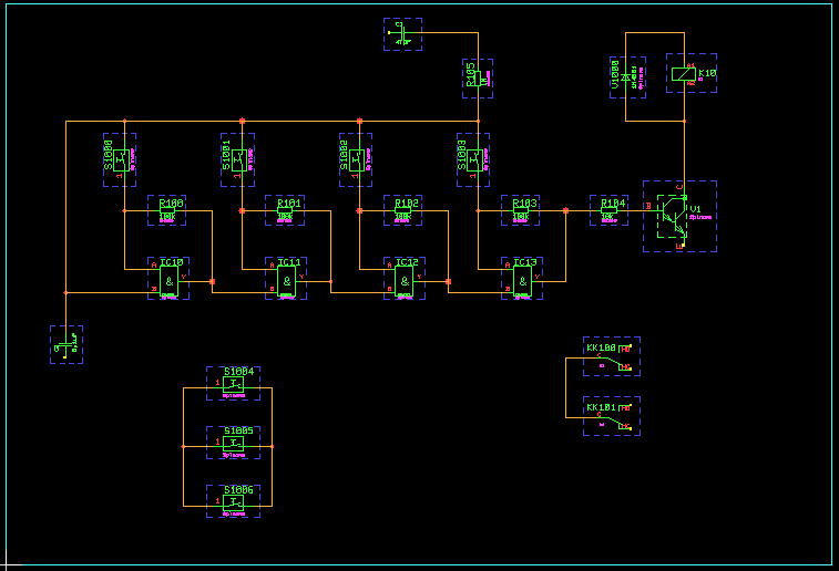
Figure 2-5: SCM Sheet with Symbols, Connections
Labels are special symbols to be utilized for defining net names. Labels can be applied for assigning certain signal names to connections. Label-defined signal names are known throughout all sheets of the schematics, i.e., labels can also be applied for connecting nets on different sheets.
In
chapter 2.2.3 we created the two label symbols
vss (0V CMOS supply) and
vdd (positive CMOS supply) in our job file
demo.ddb. I.e., these two symbols are available in the currently edited project file and can be loaded to the sheet using the
function from the
menu.
Use the following commands to define the signal
Vss by placing the label symbol
vss on the circuit drawing:
| View |
| Zoom All |
| Zoom Window |
| Move to Window Start Point, [120,160] |
| Move to Window End Point, [180,200] |
| Symbols |
| Add Label |
| Net Name ? | vss |
| Move to [130,190] |
Use the following commands to connect pin
1 of capacitor
C100 with signal
Vss by creating a connection between the capacitor pin and the previously placed label:
| Connections |
| Add Connection |
| Move to Label Pin,[130,190] |
| Move to Pin "C100.1",[140,190] |
Take care that the contact area of the label pin will extinguish in order to ensure a correct connection between the capacitor and signal
Vss.
It is not necessary to explicitly connect a label if the label is placed to a connection corner point. Use the following commands to load the label symbol
Vdd, and connect this label to the connection between capacitor
C100 and resistor
R105:
| Symbols |
| Add Label |
| Net Name ? | vdd |
| Move to Connection Corner Point, [170,190] |
Again take care that the contact area of the label pin will extinguish.
If no special label symbol for the requested net name is defined and/or available, then the system uses the default label symbol named
standard (presuming that at least this label symbol is available in the project file or in the selected library). Use the following commands to assign signal name
NET to the connection at pin
1 of switch
S1004:
| Zoom All |
| Zoom Window |
| Move to Window Start Point, [10,40] |
| Move to Window End Point, [100,100] |
| Symbols |
| Add Label |
| Net Name ? | net |
| Set Angle |
| Angle (Deg./(R)ad.) ? | 180 |
| Move to Connection Corner Point, [70,70] |
On default, the
standard label symbol is used when placing labels for net names without name-matching label symbol. This default label symbol can be changed through the
parameter setting of the
dialog from the
menu. This feature allows for the assignment of different label symbols to certain net names and/or net types without having to define a net-specific label symbol for each of these nets.
As shown in the example above the same placement functions apply for labels and symbols. I.e., you can rotate labels, set a standard placement angle, specify absolute placement coordinates, etc.
Now you should load and place further labels to get a circuit drawing as shown in
figure 2-6 (connect label
Vss to pins
V1.E,
C101.1 and
S1006.2; connect label
Vdd to pins
K10.A1 and
KK100.C; connect label
NET to pin
IC10.B). It is recommended to apply the
function for the repeated placement of the same label. You should also utilize the popup menu for selecting the label and/or signal name. This net name popup menu is activated when pressing a mouse button or typing the question-mark string
(?) to the net name query. The net name popup offers a menu with all signal names of the currently loaded SCM sheet, i.e., the net name menu does contain all those labels which are already connected to pins of the currently defined net list. The
button of the net name popup menu is used for activating the
function.
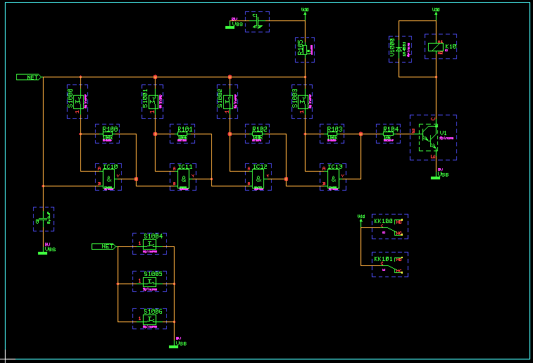
Figure 2-6: SCM Sheet with Symbols, Connections, Labels
The BAE design system instantly updates the net list with the circuit drawing. I.e., the Schematic Editor is capable of controlling and correlating the net list data with the circuit diagram at any stage of the design process. Use the following commands to test this most important feature:
| Highlight Net |
| Move to Connection |
The function from the menu is used to mark all connections of the selected net with a special ("Highlight") color. The function works as a toggle; to reset the highlight of a certain net simply re-select that net with the function. In BAE HighEnd, the function causes a highlight and/or de-highlight of the selected nets in all currently loaded plans of the current project file on schematic sheet and layout board level (global net highlight, cross-probing).
The Schematic Editor provides an built-in signal router for performing automatic connection re-routing when moving symbols and/or labels or groups on SCM sheet level. Signal routing can be activated and/or deactivated through the dialog from the menu or with the and/or options from the function submenu to be activated by pressing the right mouse button whilst moving a symbol or label. The selected signal routing mode is saved with the currently loaded SCM sheet (see also chapter 2.1.5).
Please note that the signal router should be considered "as-is", i.e., it is straight-forward designed with the intention to simplify work rather than to provide an academically optimum SCM autorouter solution with a long time-to-application/user period. We are aware of the fact that the signal router could produce unpredictable results (e.g., elimination of connections) in cases where symbol movement might cause net list conflicts. It is recommended to move symbols in a step-by-step approach rather than to move long distances and to refrain from placing symbols onto each other. You can always use the function and retry in cases where you are not pleased with the result.
The next operation is to connect the pins on the right side of the relay contacts
KK100 and
KK101 to a bus. First of all use the following commands to zoom to a suitable workspace:
| Zoom Window |
| Move to Window Start Point, [190,40] |
| Move to Window End Point, [290,100] |
Use the following commands to define a bus:
| Connections |
| Add Connection |
| Move to Connection Start Point,[240,90] |
| Move to Connection Corner Point,[240,50] |
| Move to Connection End Point,[250,50] |
| Define Bus |
| Move to Connection |
The definition of a bus is accomplished by defining a connection without pin contacts and then selecting that connection with the function. The system uses beam-shaped outlines for displaying bus connections.
Use the following commands to define the bus tap
OUT0 and connect that bus tap with pin
N0 of part
KK100:
| Connections |
| Tap Bus |
| Net Name (Range) ? | out0 |
| Move to Bus,[240,80] |
| Mirror |
| Move to Level of Pin "KK100.N0" |
| Add Connection |
| Move to Bus Tap "OUT0" |
| Move to Pin "KK100.N0" |
After specifying the bus pin net name the system will load the
bustap label symbol, which then can be placed on the bus; the submenu available during bus tap placement provides the
option which can be used for mirroring the bus tap to the opposite side of the bus. The
bustap symbol is a special label symbol, which is always used for displaying bus pins thus defining sub-signals on the corresponding bus (ensure that the
bustap label symbol is available in the preset library)
The bus tap net name query also accepts net name range specifications. Use the following commands to place three more bus taps named
OUT1,
OUT2 and
OUT3 (the previously selected bus tap mirror mode is still activated):
| Connections |
| Tap Bus |
| Net Name (Range) ? | out(1-3) |
| Move to Bus,[240,80] |
| Move to Level of Pin "KK100.NC" |
| Move to Level of Pin "KK101.N0" |
| Move to Level of Pin "KK101.NC" |
You should now connect the bus taps
OUT1 (to pin KK100.NC),
OUT2 (to pin KK101.N0) and
OUT3 (to pin KK101.NC).
Please note also the special menu functions for manipulating busses and/or bus taps (, , ).
The
Schematic Editor provides features for assigning bus signal names to support bus connections between different sheets of the schematics. Use the following commands to load a label named
BUS, and connect that label to the previously defined bus (take care that the contact area of the label extinguishes to ensure a correct connection):
| Symbols |
| Add Label |
| Net Name ? | bus |
| Move to Bus,[250,50] |
Figure 2-7 illustrates the
Bartels AutoEngineer features for bus definitions. The two bus signals
S1 in
figure 2-7a are not connected since they are tapped to different busses. In
figure 2-7b the bus signals
S1 are tapped to the same bus, i.e., they are connected.
Figure 2-7c illustrates how to define sub-busses
(DATA and
ADDR); the bus signals
S1 are not connected since they are tapped to different sub-busses.
Figures 2-7d and 2-7e show how to use labels for the assignment of bus signal names. The signals
S1 in
figure 2-7d are tapped to busses with the same label
(BUS) and thus are connected, whilst in
figure 2-7e the signals
S1 are tapped to busses with different labels
(BUS1 and
BUS2) and thus are not connected.
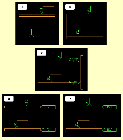
Figure 2-7: SCM Bus Connections
Text and graphic can be defined on SCM sheet level. Use the following commands to draw a graphic frame with a legend box around your circuit drawing:
| Graphic |
| Add Graphic Line |
| Move to [10,10] |
| Move to [290,10] |
| Move to [290,200] |
| Move to [10,200] |
| Move to [10,10] |
| Done |
| Add Graphic Line |
| Move to [290,40] |
| Move to [220,40] |
| Move to [220,10] |
| Done |
| Add Dot Line |
| Move to [290,20] |
| Move to [220,20] |
| Done |
Use the following commands to enter the text strings
DEMO (with text size 10mm) and
sheet1 (with text size 4mm) to the previously defined legend box:
| Text |
| Add Text |
| Text ? | DEMO |
| Text Size |
| Text Size ( 4.00mm) ? | 10 |
| Move to [230,25] |
| Add Text |
| Text ? | sheet1 |
| Text Size |
| Text Size (10.00mm) ? | 4 |
| Move to [230,13] |
Special design items such as legend boxes, company logos, etc. can also be defined as virtual symbols, and then placed to the circuit drawing. Use the following commands to place the
logo symbol for displaying the Bartels company logo:
| Symbols |
| Add Symbol |
| Part Name ? | |
| Library Element Name ? | logo |
| Move to [190,10] |
Group functions belong to the most powerful BAE features. These functions can be used for tasks such as move, copy, delete or replicate arbitrarily selectable parts of the design.
The group functions are featuring set principles. Elements can be added (selected) to or removed (deselected) from the currently defined group. Highlight display is used to indicate group-selected items. The function is used to select and/or deselect parts, traces, areas, texts or elements of any type by defining an area around the items to be selected. The function is used to select and/or deselect single elements of a certain type (symbols/labels, connections, graphic or text) by picking the desired items. The function will stay active with its parameter settings as long as valid pick elements are selected (thus omitting the need of reactivating the function when selecting a series of objects of a certain type). The function is used to deselect all items which are selected to the currently defined group. All group-selected elements are subject to subsequent group functions such as , , and .
The function is used to save the currently defined group. The function requires a group origin definition which becomes the origin of the new element and is used as the reference point for group load commands When saving groups they are stored as an element of the same type as that from which the group was selected. To prevent from unintentionally overwriting existing database elements, prompts for confirmation if the specified element already exists in the destination file.
The function can be used to reload previously saved groups (as well as SCM sheet and/or symbol/label elements) to different SCM plans and/or symbols/labels. I.e., the and functions can be used for a variety of tasks such as replicating circuitry, saving and loading SCM templates, stealing from existing and proven designs, etc.
Pressing the right mouse button during group movement operations such as , or will activate a submenu which provides functions for placing the group to relative or absolute coordinates (, ), or rotating and/or mirroring the group (, , , , ).
The function is used to replace group-selected symbol macros (on SCM sheet level) or marker macros (on symbol level). This function is most useful for fast part or pin type replacement (technology change). Attribute assignments and text positions from the original elements are transferred to the new elements if possible.
The function first resets the currently defined group to deselect all currently group-selected elements before performing the load operation. After successfully loading a group, all loaded group elements are automatically group-selected. The advantage of this feature is that loaded group elements (and only these objects) can be subject to subsequent group functions without the need to perform any group selection and/or deselection.
Use the following commands to select a group containing the switches
S1004,
S1005 and
S1006 and copy that group to the right:
| Groups |
| Group Polygon |
| All |
| Select |
| Move to [50,10] |
| Move to [110,10] |
| Move to [110,80] |
| Move to [50,80] |
| Done |
| Copy Group |
| Move to [70,70] |
| Move to [130,70] |
| Reset Group |
With the commands above three symbols and two labels have been placed, and a series of connections have been generated. Note that the system has performed automatic part naming on the copied symbols.
If you have executed all operations of this paragraph correctly, then
sheet1 of your circuit diagram should look like the one shown in
figure 2-8.
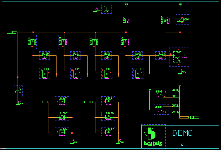
Figure 2-8: SCM Sheet Demo/Sheet1
Don't forget to save the circuit drawing with the following commands:
| File |
| Save Element |
The save operation can be activated at any time. It is recommended to save the design generally after a certain time of editing to minimize any possible loss of data caused by power failure, hardware crash, etc.
The submenus to be activated during group placement with the , and functions provide the option. This option renames and/or renumbers all currently selected parts according to their symbol part name patterns with part numbering starting at 1, and collisions with existing part names being avoided. This feature can be used for creating consecutive part numbering for the currently selected symbol group.
With the operations above we have defined the complete (logical) circuitry of our project on
sheet1 of the schematic drawing. What still is missing is the plug pin assignment, which we can define on a second schematic sheet of the project file.
Use the following commands to create a second sheet named
sheet2 in job file
demo.ddb and place the text string
Plug Pin Assignment:; also place the
x_subd9b plug symbol and assign value
xsubd9bl to the
$plname attribute of that symbol:
| File |
| New |
| Sheet |
| File Name ? | demo |
| Element Name ? | sheet2 |
| A4 Landscape |
| Text |
| Add Text |
| Text ? | Plug Pin Assignment: |
| Place |
| Symbols |
| Add Symbol |
| Part Name ? | |
| Library Element Name ? | x_subd9b |
| Place |
| Assign Value |
| Move to Symbol |
| $plname |
| Attribute Value ? | xsubd9bl |
You now should connect the signals
Vss,
Vdd and the bus signals
OUT(0-3) of
BUS to the plug symbol (see
figure 2-9 for pin assignments).
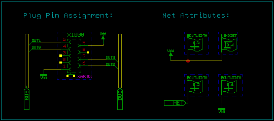
Figure 2-9: SCM Sheet Demo/Sheet2
Bartels AutoEngineer supports net-specific attributes for controlling the Autorouter such as trace width, minimum distance, net routing priority, and power supply routing width.
Place both the label
NET and the symbol
att_rw (net attribute
ROUTWIDTH) as shown in
figure 2-9, connect the pins of the
NET label and the
att_rw symbol with each other and assign a value of "0.5" to the
$val attribute of the
att_rw symbol. This net attribute assignment will cause the
Autorouter to route the net named
NET with a trace width of 0.5mm.
Place the label
Vdd as shown in
figure 2-9 and connect this label to the
att_rw symbol (with value "0.5" for the
$val
ROUTWIDTH attribute) and to the
att_md symbol (with value "0.4" for the
$val
MINDIST attribute). These net attribute assignments will cause the
Autorouter to route the net named
Vdd with a trace width of 0.5mm and a minimum distance (i.e., spacing) of 0.4mm.
Use the same procedure as described above to define a trace width of 0.6mm for the net named
Vss (place label
Vss and connect it to symbol
att_rw with a value of "0.6" for the
$val attribute).
Bartels AutoEngineer also supports the
PRIORITY and
POWWIDTH net attributes for controlling the
Autorouter. See the description of the
loglib utility program for more details on net attribute definitions.
Finally, place the
Net Attributes: text string to the circuit diagram as shown in
figure 2-9 and don't forget to save the circuit drawing.
Tag symbols can be used for assigning attributes and/or attribute sets to (groups of) parts, pins or nets. This feature can also be used to introduce more complex design information such as preferences for test procedures or logical relations between parts, pins and/or nets.
The function from the menu can be used to change the currently loaded symbol to either a or a . assignments are transferred to the physical net list. assignments are only processed on SCM sheet level.
The SCM color setup provides the and entries for displaying tags and/or tag assignments. Usually, tags are not plotted.
Tag symbol pins of certain types are required for assigning tag symbol entries to nets, symbols or pins, respectively. from the submenu to be activated with the right mouse button during pin placement can be used to define the pin mode. The pin modes provided are (for standard symbols and labels), (for assigning tags to symbols), (for assigning tags to pins) and (for assigning tags to nets).
At least one attribute should be defined with each tag symbol by either placing the required attribute name on tag symbol level or by defining a fixed attribute value assignment with the logical library definition of the tag symbol. In the logical library definition of tags each tag symbol pin must be referred by a loglib pin command. Pure attribute definition tags must be defined virtual.
On SCM sheet level, tags can be placed using the
function from the
menu. Once a tag is placed, the
function can be used for assigning tags. The target objects to be selected with the
function must correspond with the tag pin types of the selected tag symbols, i.e., either a symbol, a pin or a net named by label can be assigned to each tag pin. The attribute value assignments of net list tag symbols are automatically transferred to the assigned target objects by the
Packager. Special processing of predefined attributes such as
$plname,
$rpname,
$routwidth,
$powwidth, etc. stays in effect. The
$routwidth attribute can be tagged to pins to define pin-specific routing widths by assigning the required millimeter distance value.
Certain parts of the circuitry such as legends, plug pin assignments or router control definitions often are quite similar or even equal for different designs. The Bartels AutoEngineer data base concept supports multiple use of such circuit design templates, i.e., templates can be defined and referred as if they would be library elements. Templates can be saved and copied either by using group functions (, ) or by applying the function from the menu and utilizing the copyddb utility program for copying requested SCM elements to desired project files.
Don't forget to save the currently edited SCM element before exiting the Schematic Editor:
| File |
| Save Element |
Use the following commands to return from the Schematic Editor module to the BAE Main Menu (BAE Shell):
| File |
| Main Menu |
The currently loaded SCM element will automatically be saved when returning to the BAE Shell. Use the following commands to return from the BAE Shell to the operating system:
| Exit BAE |
Use the following commands if you wish to exit BAE from the Schematic Editor:
| File |
| Exit BAE |
The function activates a confirmation prompt if the element currently loaded to the Schematic Editor has not yet been saved. In this case you should abort the function, save the current element, and then call again, as in:
| File |
| Exit BAE |
| Please confirm (Y/N) : | n |
| File |
| Save Element |
| File |
| Exit BAE |
Use the following command from operating system level (e.g., under DOS) to list the project file(s) created in this chapter.
> dir demo.*
The job file
demo.ddb contains the all SCM sheets of the schematic circuit as well as a logical, unpacked net list. The next task of the design cycle would be to apply the
Packager for translating the logical net list into a physical, packed net list (see
chapter 3.2). After successfully packaging the net list the printed circuit board design can be created using the BAE Layout modules (see
chapter 4).
The SCM functions for generating HP-GL, HP Laser, or Postscript output are provided with the
menu of the
Schematic Editor. SCM plots can only be generated with an element loaded. I.e., you should first start the
Schematic Editor, and load the SCM sheet
sheet1 from the
demo.ddb file using the following commands:
| File |
| Load |
| Sheet |
| File Name ? | demo |
| Element Name ? | sheet1 |
The
function is used for specifying the plot data output device. The output can either be written to a file or directly to the plotter and/or printer. When plotting to a file, the desired output file name must be specified. When writing directly to the plotter, the name of the output port where the plotter is connected to (e.g.,
com2,
lpt1 under DOS) must be specified. Take care that enough disk space is available when writing to a file and that the corresponding interface is correctly initialized when directing output to a hardware device. The plot functions will abort with error messages such as
Error writing ASCII file!
if neither of these requirements are met.
The system will prompt for the output device name after activating the desired output function if no default plot device is specified with the
function. Popup menus for fast plot file selection are integrated to the
,
,
and
functions of
menu. Files ending on
.ass,
.con,
.ddb,
.def,
.exe,
.fre,
.ulc and
.usf are faded out from the plot file menus for data security reasons. New plot file names can be typed in via keyboard.
The function is used to specify a scale factor for the plot output. The default scale factor value is 1.0. Plot scale factor value specifications can range from 0.1 to 100.0.
The function provides the options and . The option sets the 0 degree plot rotation (which is the default). The option will produce a 90 degree counter-clockwise rotated plot output. Negative output coordinates might be produced when rotating plots. Some printers or plotters refuse to process negative coordinates. Positive output coordinates can be enforced however by replacing the origin of the plot element. I.e., the function from the menu can be used to set the origin to the upper left element corner before producing a rotated plot.
The function is used to define the pen width for generating the HP-GL output data. The default plotter pen width is 0.3mm. Pen width value specifications can range from 0.01mm to 10.0mm.
The
function is used to control the pen plotter speed, i.e. the speed at which the pen can be moved by the HP-GL plotter. The system accepts either
S input for maximum speed or non-negative integer plotter speed values in cm/s units. The default plotter speed corresponds with
S (maximum speed). The maximum speed value specification is 99cm/s.
The function provides the options and . causes the system to refrain from filling the plot structures, i.e., only outlines are drawn for filled areas. Switching off the fill mode is most useful for fast control plots. is used to select the default fill mode.
The
function is used to produce pen plots in HP-GL (Hewlett-Packard Graphics Language). The user is prompted for the pen number (1..99) and for the name of the output file (if no default output device was specified with
). Use the following commands to switch off the fill mode, set the plotter pen width to 0.1mm, and then plot the currently loaded SCM sheet to an HP-GL plot file named
demo_s1.plt using pen number 4:
| Plot Output |
| Plotter Pen Width |
| Plotter Pen Width ( 0.30mm) ? | 0.1 |
| Fill Mode HP-GL |
| Fill Mode Off |
| HP-GL Output |
| Plotter Pen Number (1..99) ? | 4 |
| Plot File Name ? | demo_s1.plt |
The system will issue the following message after successfully generating the HP-GL plot:
HP-GL plot done!
A
PG HPGL command is added to the end of HPGL output files to force a page eject and to prevent from subsequent plots being plotted onto the same sheet.
The
function is used to produce HP Laser plots in PCL (Printer Command Language) format. HP Laser plots are automatically scaled to A4 paper size, i.e., neither plot scaling factor nor pen width settings have effect. Use the following commands to generate an HP Laser plot of the currently loaded SCM sheet and direct the output to
lpt1 (e.g., for interfacing an appropriate DOS-connected laser writer device):
| Plot Output |
| HP Laser Output |
| Plot File Name ? | lpt1 |
The system will issue the following message after successfully generating the PCL plot:
HP Laser output done (scale 1:...)!
The scale information in the status messages indicates any non-default scaling factor being used for automatic plot to sheet size scaling.
Binary copy mode is required for transferring PCL plot data to the desired output device. I.e., the
/b option must be used when sending PCL files from hard disk to laser printer with the DOS COPY command as in
> copy pclplot lpt1 /b
with
pclplot being the PCL plot file name and
lpt1 designating the output device.
The
function is used to produce output in Postscript format. Use the following commands to set the standard line width to 0.25mm and the scaling factor to 0.75, and generate a Postscript output file named
plot1.ps for the currently loaded SCM sheet:
| Plot Output |
| Plotter Pen Width |
| Plotter Pen Width ( 0.10mm) ? | 0.25 |
| Plot Scale |
| Plot Scale Factor (1.0) ? | 0.75 |
| Postscript Output |
| Plot File Name ? | plot1.ps |
The system issues the following message after successfully generating the Postscript output:
Postscript output done!
A generic print/plot output function is implemented with the Windows versions of the BAE PC software. I.e., any print/plot output feature supported by the current Windows operating system configuration is also supported with the Schematic Editor of the BAE Windows software.
Use the following commands to activate the Windows print/plot menu:
| Plot Output |
| Generic Output |
The Windows printer dialog specifications for the number of copies, page sorting mode and page range are considered by the function.
The option from the Windows printer dialog of the function plots all elements of the currently loaded database class. This allows for the output of, e.g., all sheets of a schematic circuit. All SCM sheets are plotted according to specific plot parameter settings such as plot rotation modes.
The option from the Windows printer dialog allows for the selection of the print area for generic outputs.
The generic output is automatically scaled to the print page format selected through the Windows printer setup if the size of the element to be plotted exceeds the paper size. The page aspect ratio is maintained when automatic plot scaling is applied. The status message of the function provides information to indicate any non-default scaling factor being used for automatic plot to sheet size scaling.
The function from the menu can be used under Windows for plotting a bitmap of the currently loaded element into the clipboard ready to be imported (d) to other Windows applications capable of processing bitmaps. The whole element is plotted on default. The option can be used to restrict the output to a mouse-selectable rectangle. The plot dialog box also allows for bitmap size specifications and plot rotation mode selection.
The Schematic Editor provides functions for creating hierarchical schematic designs. Through these functions it is possible to define schematic sheets to be sub-blocks and to reference sub-blocks from higher level schematic plans. This high-sophisticated SCM design feature is recommended especially for experienced users designing large projects with replicated parts of the circuitry. Hierarchical circuit design usually is applied for the development of integrated circuits such as gate arrays, standard cells or ASICs.
The schematics for the sub-block can be defined on one or more sheets. The
option of the
function from the
dialog is used for assigning a sub-block name to the sub-block circuit drawing. Identical sub-block names must be set for different sheets defining the same sub-block.
Figure 2-10 shows an example for a sub-block circuit drawing named
BLOCK. Connections to higher hierarchy levels (i.e., the sub-block's pins) are defined by module ports. The system uses a standard label symbol named
port for module ports. The
function from the
menu is used for defining and placing module ports. The
and
functions from the
menu can be used for moving and/or deleting module ports. In
figure 2-10 the module ports
S,
R,
Q,
/Q and
HYPER are defined. Within hierarchical circuit design there is a difference between global and local net names. A local net is defined by preceding the net name with an ampersand
(&) character. Hence the nets named
&ABC and
/&ABC in
figure 2-10 are defined locally in all sheets with the same blockname. Standard net name allocation (such as at
VCC) introduces a global net definition which connects on all sheets, no matter what hierarchy level the net name is defined on. When using a global net name in a sub-block, all matching nets from multiple referenced sub-blocks are connected as well.
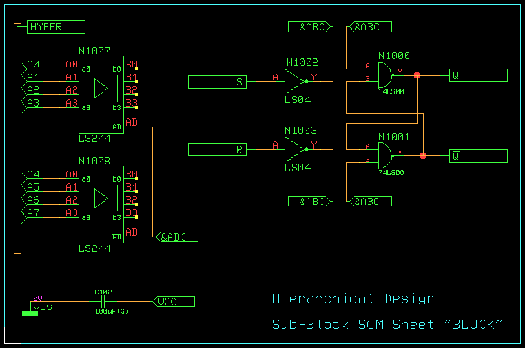
Figure 2-10: Hierarchical Circuit Design; Sub-Block SCM Sheet "BLOCK"
The
parameter setting also provides the
option for block diagramming support. Whilst there are multiple references to a standard
allowed, a
sheet can only be referenced once. Single sub-blocks are treated like normal SCM sheets by
Packager and
. I.e., the
Packager transfers symbol/part names from single sub-blocks without
[Pn] prefices to the layout, and
transfers part name changes and pin/gate swaps on single sub-blocks back to the schematics.
A special SCM symbol is required for referencing any sub-block on higher hierarchy levels. The pin names of that symbol must match the names of the module ports defined on the corresponding sub-block circuit drawing.
The Packager needs a logical reference for any sub-block reference symbol used throughout the schematics. This logical reference must be created in the Logical Library by defining a logical library file entry for the sub-block reference symbol. This loglib entry must define a virtual part with the name of the sub-block reference symbol. For referencing the sub-block, the loglib command call (with the blockname of the sub-block as argument) must be used. See also chapter 7.11 of this manual for a more detailed description of the loglib utility program.
Figure 2-11 shows the sub-block reference symbol
DFF and the corresponding logical sub-block reference for the sub-block circuit drawing in
figure 2-10. Note that
figure 2-11 also illustrates how to define busses on sub-block reference symbols.
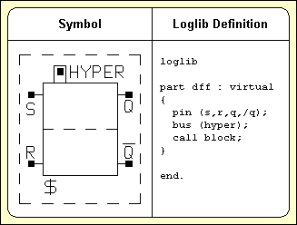
Figure 2-11: Hierarchical Circuit Design; Block Symbol "DFF" with Loglib Definition
Figure 2-12 shows how the sub-block symbol
DFF from
figure 2-11 is used in a higher level schematic drawing. The circuit drawing in
figure 2-12 contains three
DFF symbols named
DFF_1,
DFF_2 and
DFF_3, each referencing one
BLOCK sub-block circuit drawing.
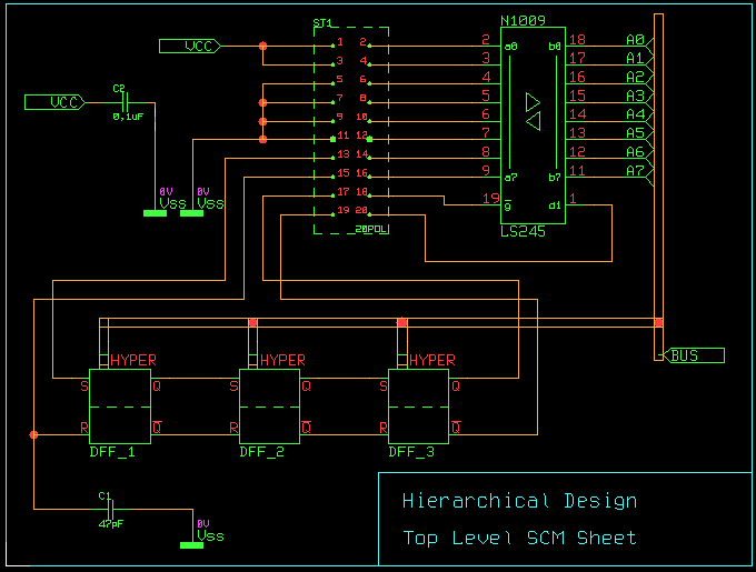
Figure 2-12: Hierarchical Circuit Design; Top Level SCM Sheet
Backward annotation with the is always required after performing layout net list modifications such as part name changes, pin/gate swaps or alternate part package type assignments. Part names can be changed using the function from the menus for interactive part placement. Interactive pin/gate swaps are applied with the function from the manual part placement menu. Automatic pin/gate swap is performed with the , and autoplacement functions, and can also be performed when using the option with the rip-up router of the Autorouter module. Alternate package types can be assigned using the submenu function during manual part placement. Note that any of the net list modifications mentioned above will get lost when re-editing the schematic without running the .
is fully integrated to the and can be explicitely started using the command from the menu. A feature for automatically processing pending requests is also integrated to the functions for loading schematic plans. requests are generated when saving layouts with net list modifications such as pin/gate swaps or changed part names. Loading an SCM sheet with a pending request automatically activates a verification menu which allows to backannotate the currently processed design. The request is deleted after successfully running the .
See chapter 3 for a detailed description on how is applied.
This chapter describes how to use the Packager program module and the function from the Schematic Editor for performing forward and backward annotation of net list data. The examples presented with this chapter introduce the basic concepts of net list data processing and annotation in the Bartels AutoEngineer in a logical sequence. The circuit design of the preceding chapter will be prepared for further processing in the subsequent chapters. The reader should work through this chapter without missing any sections to gain full understanding of Packager and . Once a command has been used and/or explained, the operator is assumed to have understood its function and be able to perform it again. Subsequent instructions containing this command will be less verbose for easier reading and more speedy learning.
| 3.1 | General |
| 3.1.1 | Components and Features |
| 3.2 | Packager |
| 3.2.1 | Starting the Packager |
| 3.2.2 | Packager Main Menu |
| 3.2.3 | Running the Packager |
| 3.2.4 | Example |
| 3.2.5 | Messages |
| 3.3 | Backannotation |
| 3.3.1 | Starting the Backannotation |
| 3.3.2 | Running the Backannotation |
| 3.3.3 | Example |
| 3.4 | Net List Utilities |
| 3.4.1 | Importing Logical Net Lists |
| 3.4.2 | Importing Physical Net Lists |
| 3.4.3 | Exporting Net List Data |
| 3.4.4 | Net Attributes |
| Figures |
| 3-1 | Design Flow Packager - Backannotation |
| 3-2 | Part CD4081 Data Sheet with Loglib Definition |
| 3-3 | Net Attribute Definitions |
The schematic capture system of the Bartels AutoEngineer essentially consists of an interactive Schematic Editor with integrated and the Packager program module for converting logical into physical netlists ("Forward Annotation"). The following sections of this manual describe in detail how to use Packager and .
Bartels AutoEngineer provides the Packager program module and the function for transferring net list data between schematics and layout. Figure 3-1 shows the design flow of forward and backward annotation using Packager and .
Editing SCM sheets with the Schematic Editor results in a logical net list. The Packager collects the interconnection information from the logical net list and generates a physical net list ready for layout. The forward annotation process is controlled by the logical library entries defining the assignments of SCM symbols to layout packages and the corresponding pin mappings (see also the description of the loglib utility program). The Packager annotates the schematic with the physical pin names to replace the logical pin names and also transfers special information such as pin/gate swap definitions, part attribute settings, power supply pinning, etc.
Layout Net list modifications such as part name changes, pin/gate swaps or part package type assignments must be backward annotated to the schematics using the function from the Schematic Editor. Running the results in a modified logical net list with annotated part and/or pin names on the corresponding SCM sheet.
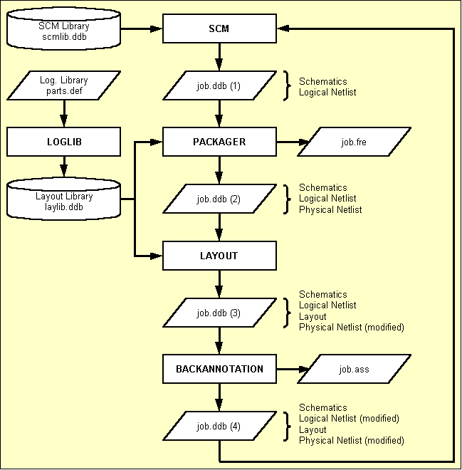
Figure 3-1: Design Flow Packager - Backannotation
Forward annotation with the Packager is always required after introducing net list changes with the Schematic Editor such as loading symbols to the schematic, changing the connectivity on the circuit, setting attribute values, etc.
It is recommended to start the Bartels AutoEngineer from in the directory where the design files should be generated, since this considerably simplifies job file access. If you intend to process the examples provided with this manual it is recommended to move to the BAE examples directory installed with the BAE software. The Packager can be called from the Bartels AutoEngineer main shell. Start the BAE shell by typing the following command to the operating system prompt:
> bae
The AutoEngineer comes up with the Bartels logo and the following menu (the function is only available under Windows/Motif; the and menu items are available only with special software configurations such as BAE HighEnd or BAE IC Design):
| Schematic |
| Layout |
| [ IC-Design ] |
| Packager |
| CAM-View |
| [ Setup ] |
| [ Next Task ] |
| Exit BAE |
Move the menu cursor to the menu item and confirm this choice by pressing the left mouse button:
| Packager |
Now the Packager program module will load. If this fails to happen then check your BAE software installation (see the Bartels AutoEngineer® Installation Guide for details on how to perform a correct installation).
The Packager user interface provides a menu area on the right side, consisting of the main menu on top and the currently active menu below that main menu. After entering the Packager the function with its menu is active. The main menu is always available and provides the following functions:
| Start |
| Main Menu |
| Schematic |
| Layout |
| Settings |
| Exit BAE |
The function is used to set the parameters for the Packager process to be started with the function. The , and functions are used to switch to the BAE Main Menu, the Schematic Editor or the Layout system. ends the BAE session. For designs without existing layout, layout element creation for the net list created by the Packager is automatically suggested when switching to the Layout system.
Before starting the Packager process through the function, the user must specify the parameters to be used for the Packager call using the functions from the Settings menu.
The following prompts are activated after calling the function from the menu:
| Settings |
| All Parameters |
| Design File Name ? |
| Design Library Name ? |
| Layout Element Name ? |
Each of these parameters can also be set explicitely through the corresponding functions from the menu.
The design file name is the name of the project file to be selected for packaging. The design file must be available with extension
.ddb but this extension must not be included with the file name specification. If the user types an empty string (by pressing the return key
![]() ) to the design file name prompt, then the system will automatically use the file name of the previously processed element (i.e., the global project name).
) to the design file name prompt, then the system will automatically use the file name of the previously processed element (i.e., the global project name).
The design library name is the name of the layout library file to be used for the PCB design. This file must also contain the logical library definitions required for packaging. The design library file must be available with extension
.ddb but this extension must not be included with the file name specification. If the user types in an empty string (by pressing the return key
![]() ) to the design library name prompt, then the system will automatically refer to the default layout library file name defined with BAE setup (see also command
) to the design library name prompt, then the system will automatically refer to the default layout library file name defined with BAE setup (see also command
LAYDEFLIBRARY of the
bsetup utility program).
The layout element name is the name of the layout and/or the net list to be generated. The layout element name is freely selectable when packaging a certain design for the first time. If the user types in an empty string (by pressing the return key
![]() ) to the layout element name prompt, then the system uses the default layout element name defined with BAE setup (see also command
) to the layout element name prompt, then the system uses the default layout element name defined with BAE setup (see also command
LAYDEFELEMENT of the
bsetup utility program).
After successfully processing all SCM sheets, the
Packager generates a physical net list with the same name as specified for the layout board element. That layout board element can then be created, parts placed and traces routed. For user information purposes, the
Packager also creates a free list file with file name extension
.fre. The free list is an ASCII file containing an unconnected pins report and statistical information such as net pin counts.
The system issues the message after successfully completing the packaging process, and the user can press any key to return to the BAE main menu. Errors during packaging usually result from wrong and/or missing logical library entries. In this case the logical library must be corrected before re-running the Packager (see the description of the loglib utility program for details on how to define logical library entries).
Saving a layout with pin/gate swaps and/or net list part name changes creates a design-specific request. The Packager checks for requests and activates a verification to prevent the Packager from forward annotation without confirmation. Confirmation to run the Packager will discard any layout net list changes not yet backannotated.
The
Packager automatically transfers SCM symbol pin names to the
$llname pin attribute. This allows for the display of logical pin names in the layout by defining
$llname texts on padstack level.
$nettype pin attributes are automatically transferred to connected nets. The
$nettype value
mixed is assigned to nets with different
$nettype attribute values.
The
BAE HighEnd
Packager automatically transfers
$drcblk pin attributes to connected nets. The
$drcblk attribute value addresses a
BAE HighEnd design rule check parameter block to be assigned to the corresponding net.
The
Packager evaluates
$pintype pin attribute settings to perform electrical rule checks (ERC). It is recommended to assign fixed ERC pin types through the logical symbol/part definitions. The following pin type attribute value settings are supported:
$pintype | Pin Type |
|---|---|
in | Input Pin |
out | Output Pin |
bidi | Bi-directional Pin |
anl | Analog Pin |
sup | Power Supply Pin |
The ERC issues a warning message such as if a net with one or more input pins has no (normal, bi-directional or power supply) output pin. A warning message such as is issued if a normal output pin is connected to another output pin, a bi-directional pin or a power supply pin.
This section describes how to run the
Packager on the
demo.ddb example project file which has been created in the previous chapter. I.e., you should change to the directory where the
demo.ddb file resides.
Start the BAE main menu, call the
Packager as described in
chapter 3.2.1, and use the following commands to run the
Packager for transferring the logical net list in
demo.ddb to a physical net list named
board using library
demolib.ddb:
| Settings |
| All Parameters |
| Design File Name ? | demo |
| Design Library Name ? | demolib |
| Layout Element Name ? | board |
| Start |
Errors will occur during packaging, and the following messages are displayed:
================ BARTELS PACKAGER ================ Design File Name ...........: 'demo' Library File Name ..........: 'demolib' Layout Element Name ........: 'board' Active Schematic Sheet .....: 'sheet1'. ERROR : Part 'cd4081' not in library! Abort - Database not changed!
The message at the end of the Packager protocol indicates that packaging was not successful.
Under Windows, the text window for
Packager messages is displayed with scrollbars to provide complete access to lengthy
Packager protocols without having to view the
bae.log log file (see below) through an external text editor.
Hit the return key
![]() to return to the
Packager main menu, and use the following command to exit from BAE:
to return to the
Packager main menu, and use the following command to exit from BAE:
| Exit BAE |
You are now back on operating system level. The
Packager report has been written to an ASCII file named
bae.log in the current directory. You can examine this file with your editor (or send it to your printer) to interpret the
Packager report. The
Packager process stopped with the following error message:
ERROR : Part 'cd4081' not in library!
The error message above means that library
demolib.ddb does not contain any logical library entry for SCM symbol
cd4081.
cd4081 is the new SCM symbol created in
chapter 2.2.2. The system only knows that this symbol is repeatedly referenced on SCM sheet
sheet1 of the
demo.ddb project file, and that the logical pins of
cd4081 are named
A,
B and
Y. The SCM symbol
cd4081 represents only one of the four gates of the complete CD4081 part. The
Packager needs additional information such as the layout package associated with
cd4081, logical to physical pin mapping, predefined power supply pins and pin/gate swap definitions.
SCM sheets which can be singled out to have caused Packager errors are automatically loaded when switching from the menu-driven Packager versions to the Schematic Editor. In that case, the Schematic Editor also triggers a to the first SCM symbol which caused a Packager error.
A
loglib file must be edited to provide the missing information about the assignment of SCM symbol
cd4081 to its corresponding layout package. The
loglib utility program must then be applied to transfer the contents of that
loglib file to the
demolib.ddb library file to be used for packaging.
Use your editor to prepare an ASCII file named
cd4081.def containing the
loglib definition as shown in
figure 3-2.
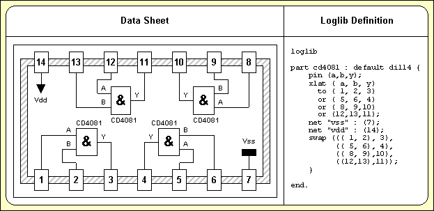
Figure 3-2: Part CD4081 Data Sheet with Loglib Definition
The following just explains the contents of the loglib definition in figure 3-2. See chapter 7.11 for a detailed description of the loglib input file syntax.
The
loglib file always starts with the
loglib keyword and ends with the
end. keyword.
The
part command is used to assign a layout package to the SCM symbol. The
default keyword in the example indicates that this assignment is not imperative, i.e., it can be changed with an appropriate value assignment to the
$plname attribute of the SCM symbol (e.g., for assigning an SMD instead of the standard DIL package).
The
pin command defines the logical pins
A,
B and
Y of the SCM symbol. Take care that this definition agrees with the pin definitions on the SCM symbol, or otherwise packaging will fail.
The
xlat is used to allocate the gates of the physical part and to define the logical to physical pin mapping.
The
swap command is used to define the rules for pin and gate swap. In the example above, the gates are mutually swapable, and the gate input pins are also swapable.
The
net command is used to define power supply pins. In the example above, pin
7 is connected to signal
Vss and pin
14 is connected to signal
Vdd.
Use the following
loglib call to translate the logical library definition from
cd4081.def and store it to the
demolib.ddb library file:
> loglib cd4081 demolib
If the definitions in
cd4081.def are correct, then the
loglib utility program should issue the following messages:
=================================== BARTELS LOGICAL LIBRARY MAINTENANCE =================================== Program run successfully done.
Now
demolib.ddb contains all information required for successfully packaging the project file
demo.ddb (see also the contents of
loglib file
demolib.def which has already been translated to
demolib.ddb).
The Schematic Editor menu provides a function named for displaying logical library part definitions of selectable symbols of the currently loaded SCM sheet.
, decodes and displays the internal logical library part definition stored with the
loglib. The logical library definition display header provides information on whether the
loglib definition was found in the current job file
() or in the default layout library
(). The current job file is searched with higher priority. The default layout library file name is specified with the
LAYDEFLIBRARY command of the
bsetup utility program (see also
chapter 7.2).
The function issues an error message such as on errors accessing the default library. An error message such as is issued if the requested logical library definition is neither available in the job file nor in the default library.
Restart the
Packager through the BAE main menu and use the following commands to call the
Packager for transferring the logical net list in
demo.ddb to a physical net list named
board using library
demolib.ddb:
| Settings |
| All Parameters |
| Design File Name ? | demo |
| Design Library Name ? | demolib |
| Layout Element Name ? | board |
| Start |
The Packager will issue the following messages on the screen:
================ BARTELS PACKAGER ================ Design File Name ...........: 'demo' Library File Name ..........: 'demolib' Layout Element Name ........: 'board' Active Schematic Sheet .....: 'sheet1'. Active Schematic Sheet .....: 'sheet2'. No error occurred!
The
message means that the packaging has been successfully completed, and a (packed) physical net list named
board was generated in the
demo.ddb project file.
The
Packager creates not only a physical net list, but also a logical net list with element name extension
_log. In the example above a logical net list named
board_log has been generated. The logical net list is not required by the system, but can be utilized for interfacing to certain foreign systems such as simulators (see also the
userlist application example in
chapter 3.4.3).
The
Packager produces a free list named
demo.fre for user information purposes only. You should examine the unconnected pins report and the net pin counts provided with this ASCII file (e.g., for checking on single pin signals).
The
Packager annotates physical net list data such as part and pin names to the schematics. Check this by examining the SCM sheet elements after successfully running the
Packager. Particularly you should have a close look at the four
cd4081 gates on
sheet1 of the example job file
demo.ddb. All these gates have the same part name now (since they are all assigned to the same physical part), and the logical pin designators
(A,
B and
Y, respectively) have been replaced by physical pin names
(1,
2,
3, etc.).
After successfully completing the
Packager process, the project is ready for layout, and you can enter the BAE
Layout Editor to start with the PCB design. The name of the layout element to be created must match the name of the net list specified with the
Packager run. I.e., the layout element name for the above-mentioned example project file
demo.ddb should be
board. Within the Layout system the library path should be set to library file
demolib.ddb which has been used for packaging, and then the net list parts can be placed (e.g., by repeatedly applying the
function from the
menu; see
chapter 4.3.2 for details).
This section provides an alphabetically sorted list of all
Packager error, warning and status messages. The
and
prefixes have been omitted since some messages are issued as errors or warnings depending on the
parameter. The messages displayed on screen are logged into a file named
bae.log and can be viewed after exiting the
Packager.
The system automatically loads the sheet with the first erroneous SCM symbol and zooms to that symbol when switching immediately to the
Schematic Editor after encountering error messages related to specific schematic symbols or their logical library definitions. The
/ and/or
/ functions can be used to view and/or edit the logical library definition if the problem is caused by the logical library definition. These functions also take
$rlname and/or
$rlext attribute settings for alternative logical library definition name assignments into account.
The Packager copies the required logical library definitions from the selected layout library file to the project file. Local, project-specific logical library definitions have priority over external logical library definitions from the layout library in subsequent Packager runs. It is important to consider this behaviour when correcting logical library definitions. The setting from / forces the Packager to restore and/or copy (corrected) logical library definitions from the layout library.
Any symbol pin changes such as the adding, deleting or renaming of pins require all of the affected SCM sheets to be reloaded and saved to update the logical netlists. Please note that although new and/or changed symbol pin names are displayed when re-loading a sheet, the SCM sheet has to be saved to update the logical netlist accordingly.
The Packager encountered one or more errors which prevented it from creating a valid layout net list. Consequently, the Packager was aborted without writing a layout net list to the project file. If a layout net list with the selected element name already existed in the project file, then this net list is left unchanged and can be reused. Please examine the Packager transcript and/or log file for the exact error cause(s).
*** NOT YET DOCUMENTED ***
The SCM sheet with the name sheetname is currently being processed. Subsequently listed error and warning messages relate to symbols on this sheet.
This message displays the file name of the alternative layout and logical library used by the Packager. The Packager fetches and copies required layout part macros and logical library definitions from the alternative library to the project file if these definitions are neither in the project file nor in the default layout library. Since the Packager copies required layout part symbols to the project file, these part macros are available for subsequent part placement operations in the Layout Editor. The Packager saves the alternative library file name parameter in the project file, thus eliminating the need for specifying the same parameter again in subsequent Packager runs.
*** NOT YET DOCUMENTED ***
*** NOT YET DOCUMENTED ***
*** NOT YET DOCUMENTED ***
*** NOT YET DOCUMENTED ***
*** NOT YET DOCUMENTED ***
*** NOT YET DOCUMENTED ***
*** NOT YET DOCUMENTED ***
*** NOT YET DOCUMENTED ***
*** NOT YET DOCUMENTED ***
*** NOT YET DOCUMENTED ***
*** NOT YET DOCUMENTED ***
*** NOT YET DOCUMENTED ***
*** NOT YET DOCUMENTED ***
*** NOT YET DOCUMENTED ***
*** NOT YET DOCUMENTED ***
*** NOT YET DOCUMENTED ***
*** NOT YET DOCUMENTED ***
*** NOT YET DOCUMENTED ***
This message displays the currently processed project file name. The Packager converts the connections and symbols from the schematic sheets of the project file into a layout part and net list.
*** NOT YET DOCUMENTED ***
*** NOT YET DOCUMENTED ***
*** NOT YET DOCUMENTED ***
*** NOT YET DOCUMENTED ***
*** NOT YET DOCUMENTED ***
*** NOT YET DOCUMENTED ***
*** NOT YET DOCUMENTED ***
*** NOT YET DOCUMENTED ***
The Packager aborted due to an unexpected error (e.g., a list element search failed immediately after the element was saved in the list). There is likely to be either a hardware problem or an unknown error occurred which is not (yet) handled by the Packager. Please submit the project file to your Bartels support department for debugging if the error occurs with a specific project and is not sporadic (i.e., if the error can be reproduced).
*** NOT YET DOCUMENTED ***
*** NOT YET DOCUMENTED ***
*** NOT YET DOCUMENTED ***
*** NOT YET DOCUMENTED ***
*** NOT YET DOCUMENTED ***
*** NOT YET DOCUMENTED ***
*** NOT YET DOCUMENTED ***
*** NOT YET DOCUMENTED ***
*** NOT YET DOCUMENTED ***
*** NOT YET DOCUMENTED ***
*** NOT YET DOCUMENTED ***
*** NOT YET DOCUMENTED ***
*** NOT YET DOCUMENTED ***
*** NOT YET DOCUMENTED ***
*** NOT YET DOCUMENTED ***
*** NOT YET DOCUMENTED ***
This error message is issued if the Packager (logpack.exe and/or logpack) is called directly from a DOS and/or UNIX/Linux shell. The Packager must be called from the BAE user interface to ensure that the required setup file and library path names are known and that the Packager can change (back) to the other BAE modules.
*** NOT YET DOCUMENTED ***
*** NOT YET DOCUMENTED ***
*** NOT YET DOCUMENTED ***
*** NOT YET DOCUMENTED ***
*** NOT YET DOCUMENTED ***
*** NOT YET DOCUMENTED ***
*** NOT YET DOCUMENTED ***
*** NOT YET DOCUMENTED ***
*** NOT YET DOCUMENTED ***
*** NOT YET DOCUMENTED ***
This message displays the name of the layout netlist to be created by the Packager. The same element name should be specified when (subsequently) creating the layout for this net list.
*** NOT YET DOCUMENTED ***
This message displays the file name of the default layout and logical library used by the Packager. The Packager fetches and copies required layout part macros and logical library definitions from the default library to the project file if these definitions are not yet in the project file. Since the Packager copies required layout part symbols to the project file, these part macros are available for subsequent part placement operations in the Layout Editor. The Packager saves the library file name parameter in the project file, thus eliminating the need for specifying the same parameter again in subsequent Packager runs.
*** NOT YET DOCUMENTED ***
*** NOT YET DOCUMENTED ***
*** NOT YET DOCUMENTED ***
*** NOT YET DOCUMENTED ***
*** NOT YET DOCUMENTED ***
*** NOT YET DOCUMENTED ***
*** NOT YET DOCUMENTED ***
*** NOT YET DOCUMENTED ***
*** NOT YET DOCUMENTED ***
*** NOT YET DOCUMENTED ***
*** NOT YET DOCUMENTED ***
*** NOT YET DOCUMENTED ***
*** NOT YET DOCUMENTED ***
*** NOT YET DOCUMENTED ***
*** NOT YET DOCUMENTED ***
*** NOT YET DOCUMENTED ***
*** NOT YET DOCUMENTED ***
*** NOT YET DOCUMENTED ***
*** NOT YET DOCUMENTED ***
*** NOT YET DOCUMENTED ***
*** NOT YET DOCUMENTED ***
There was not enough main memory available for successfully processing the project data. It is highly unlikely that this error occurs with today's hardware configurations unless the computer's main memory is used to capacity by other processes.
The selected menu function and/or option is not available. This is usually due to the use of an intermediate and/or preliminary BAE version which displays menu functions or options which are not yet implemented. Please be patient, the selected function/option will be fully implemented in one of the next BAE versions and/or builds.
*** NOT YET DOCUMENTED ***
*** NOT YET DOCUMENTED ***
*** NOT YET DOCUMENTED ***
*** NOT YET DOCUMENTED ***
*** NOT YET DOCUMENTED ***
*** NOT YET DOCUMENTED ***
*** NOT YET DOCUMENTED ***
*** NOT YET DOCUMENTED ***
*** NOT YET DOCUMENTED ***
*** NOT YET DOCUMENTED ***
*** NOT YET DOCUMENTED ***
*** NOT YET DOCUMENTED ***
*** NOT YET DOCUMENTED ***
*** NOT YET DOCUMENTED ***
*** NOT YET DOCUMENTED ***
*** NOT YET DOCUMENTED ***
*** NOT YET DOCUMENTED ***
*** NOT YET DOCUMENTED ***
*** NOT YET DOCUMENTED ***
*** NOT YET DOCUMENTED ***
*** NOT YET DOCUMENTED ***
*** NOT YET DOCUMENTED ***
*** NOT YET DOCUMENTED ***
*** NOT YET DOCUMENTED ***
*** NOT YET DOCUMENTED ***
A problem occurred when processing the layout part with the name layoutpartname. Please examine subsequent error message for more detailed information.
A problem occurred when processing the schematic symbol with the name symbolname. Please examine subsequent error message for more detailed information.
A problem occurred when processing the (variant) layout part with the name layoutpartname. Please examine subsequent error message for more detailed information.
*** NOT YET DOCUMENTED ***
*** NOT YET DOCUMENTED ***
*** NOT YET DOCUMENTED ***
The logical library definition of the symbol symbolname contains multiple newattr commands with different value assignments to the attributname attribute.
This problem can be fixed by removing the redundant/ambiguous newattr commands from the logical library definition of the symbol.
*** NOT YET DOCUMENTED ***
*** NOT YET DOCUMENTED ***
*** NOT YET DOCUMENTED ***
*** NOT YET DOCUMENTED ***
*** NOT YET DOCUMENTED ***
*** NOT YET DOCUMENTED ***
*** NOT YET DOCUMENTED ***
*** NOT YET DOCUMENTED ***
*** NOT YET DOCUMENTED ***
*** NOT YET DOCUMENTED ***
*** NOT YET DOCUMENTED ***
*** NOT YET DOCUMENTED ***
Either the specified project file name or the specified library file name contains invalid (control) characters or ? and/or * characters, or the project file name ( / ) was not set.
Please set a project file name and/or use file names without special characters to avoid this problem.
The layout element (net list) name specified through / is either empty or contains invalid (control) characters or ? and/or * characters.
Please set a valid layout element without special characters to avoid this problem.
*** NOT YET DOCUMENTED ***
*** NOT YET DOCUMENTED ***
*** NOT YET DOCUMENTED ***
*** NOT YET DOCUMENTED ***
*** NOT YET DOCUMENTED ***
*** NOT YET DOCUMENTED ***
Backward annotation with the is always required after performing layout net list modifications such as part name changes, pin/gate swaps, or alternate part package type assignments. Part names can be changed using the function from the menus for interactive part placement. Interactive pin/gate swaps are applied with the function from the manual part placement menu. Automatic pin/gate swap is performed with the , and autoplacement functions, and can also be performed when using the option with the rip-up router of the Autorouter module. Alternate package types can be assigned using the submenu function during manual part placement. Note that any of the net list modifications mentioned above will get lost when re-editing the schematic without running the .
is fully integrated to the Schematic Editor and can be explicitely started using the command from the menu.
A feature for automatically processing pending requests is integrated to the Schematic Editor functions for loading schematic plans. requests are generated when saving layouts with net list modifications such as pin/gate swaps or changed part names. Loading an SCM sheet with a pending request automatically activates a verification menu which allows to backannotate the currently processed design. The request is deleted after successfully running the .
Design and/or project file name and layout element name prompts are activated after calling (pressing the ESC key aborts the ):
| Utilities |
| Backannotation |
| Design File Name ? |
| Layout Element Name ? |
The design file name is the name of the project file to be selected for
. The design file must be available with extension
.ddb but this extension must not be included with the file name specification. If the user types an empty string (by pressing the return key
![]() ) to the design file name prompt, then the system will automatically use the file name of the currently loaded or the previously processed element (i.e., the global project name).
) to the design file name prompt, then the system will automatically use the file name of the currently loaded or the previously processed element (i.e., the global project name).
The layout element name is the name of the layout and/or the net list to be backannotated. If the user types in an empty string (by pressing the return key
![]() ) to the layout element name prompt, then the system uses the default layout element name defined with BAE setup (see also command
) to the layout element name prompt, then the system uses the default layout element name defined with BAE setup (see also command
LAYDEFELEMENT of the
bsetup utility program).
After successfully processing the layout the
will generate a modified logical net list in the project file. For user information purposes
also creates an assignments file under the design file name with extension
.ass. The assignments file is an ASCII file containing an annotation report (part name changes, logical to physical pin mapping).
The system issues the message after successfully completing the process, and the user can press any key to exit from the function. Errors during usually result from a wrong layout element name specification and/or from missing logical net list data. Missing SCM symbols and/or parts could also prevent the from completing successfully. The lists missing symbols/parts. These must be replaced on the SCM sheet(s) to allow for subsequent processes to be completed successfully (the missing parts problem could also be "solved" by simply re-running the Packager instead of the , but all netlist-specific layout modifications scheduled for such as pin/gate swaps would then be lost).
This section describes how to run
on the
demo.ddb example project file which has been created in the previous chapter. You should change to the directory where the
demo.ddb file resides.
Start the
Schematic Editor through the BAE main menu and use the following commands to call
for transferring the physical net list named
board from the
demo.ddb design file back to the schematics:
| Utilities |
| Backannotation |
| Design File Name ? | demo |
| Layout Element Name ? | board |
displays the following messages:
============================== BARTELS BACKANNOTATION UTILITY ============================== Design File Name ........: 'demo' Layout Element Name .....: 'board' No error occurred!
The
message means that
was successfully completed and the logical net list in project file
demo.ddb has been annotated with the physical net list named
board.
produces an assignment file named
demo.ass which is not required by the BAE design system. You can use the part name changes report and the logical to physical pin mapping lists provided with this ASCII file for backannotating to foreign CAE systems.
annotates physical net list modifications such as part name changes and pin/gate swaps to the schematic sheets. You can check this by examining the SCM sheet elements after successfully running the .
Within the Bartels AutoEngineer design process the net list is usually created with the Schematic Editor. Besides that BAE provides the subsequently mentioned utilities for creating and/or converting various foreign ASCII net list formats. See also chapter 7 for a detailed description of these utility programs.
Importing logical (i.e., unpacked) net lists to the Bartels AutoEngineer requires a subsequent Packager pass to prepare for the layout design. A DDB library file for the Packager process including all of the requested layout symbols and logical library entries is required.
The netconv (Logical Netlist Conversion Utility) program is used to transfer logical net list data from BAE ASCII format to internal Bartels AutoEngineer format ready for processing with the BAE Packager.
No packaging is required when importing physical (i.e., packed) net lists to the Bartels AutoEngineer. Nevertheless, a DDB library file including all of the requested layout symbols must be available for the subsequent layout design process.
The conconv (Connection Conversion Utility) program is used to transfer physical net lists to the Bartels AutoEngineer. Supported ASCII net list formats are BAE, CALAY, MARCONI and RACAL. Net lists from other systems can often be written in one of these formats providing a convenient link between other schematic systems and the powerful BAE layout system.
The redasc (REDAC ASCII Input Interface) program is used to transfer layout data from Redac MAXI system, i.e., redasc converts layout symbols, part lists, net lists, placement information etc. from Redac CDI ASCII format to internal BAE DDB format.
Either the
Bartels User Language programming facilities (see the
Bartels User Language Programmer's Guide for details on how to apply
Bartels User Language) or the
userlist (User Programmable List Generator) utility program can be utilized to provide tools for exporting net list data in arbitrary formats. Use your editor to create a
userlist script named
netlist.usf with the following contents:
EXTENSION = ".nl";
PRINT("NETLIST ",PROJECTNAME,";",CR);
FOR (ALL PARTS)
{
PRINT(PARTNAME:-5,"(",$plname:-8,") : ");
CLEARCOUNTER;
FOR (ALL PINS)
{
IF (NETPINCOUNT > 1)
{
PRINT(PINNAME,"(",NETNAME,")");
COUNTUP;
IF (COUNTVALUE > 4) { PRINT(CR,TAB);CLEARCOUNTER; }
}
}
PRINT(";",CR);
}
ENDSPEC
Use the following
userlist call to run the
netlist.usf
userlist script to export the (physical) net list
board from job file
demo.ddb to ASCII net list file
demo.nl:
> userlist netlist demo board
The above
userlist call produces the
demo.nl net list file with the following contents:
NETLIST board;
c100 (chip1210) : 1(vss)2(vdd);
c101 (chip1206) : 1(vss)2(net);
ic10 (dil14 ) : 1(@7)10(@9)11(@2)12(@3)13(@9)14(vdd)2(net)
3(@6)4(@4)5(@5)6(@6)7(vss)8(@11)9(@4);
k1 (relais ) : a1(vdd)a2(@14)c1(vdd)c2(vdd)nc1(bus.out1)
nc2(bus.out3)no1(bus.out0)no2(bus.out2);
r100 (r04a25 ) : 1(@7)2(@6);
r101 (r04a25 ) : 1(@5)2(@4);
r102 (r04a25 ) : 1(@11)2(@9);
r103 (r04a25 ) : 1(@3)2(@2);
r104 (minimelf) : 1(@2)2(@8);
r105 (chip1206) : 1(net)2(vdd);
s1000(s1dilo ) : 1(@7)2(net);
s1001(s1dilo ) : 1(@5)2(net);
s1002(s1dilo ) : 1(@11)2(net);
s1003(s1dilo ) : 1(@3)2(net);
s1004(s1dilo ) : 1(net)2(vss);
s1005(s1dilo ) : 1(net)2(vss);
s1006(s1dilo ) : 1(net)2(vss);
s1007(s1dilo ) : 1(net)2(vss);
s1008(s1dilo ) : 1(net)2(vss);
s1009(s1dilo ) : 1(net)2(vss);
v1 (to92 ) : 1(vss)2(@8)3(@14);
v1000(d04a25 ) : a(@14)k(vdd);
x1000(xsubd9bl) : 1(vss)4(bus.out0)5(bus.out1)6(bus.out2)7(bus.out3)
9(vdd);
Use the following
userlist call to run the
netlist.usf
userlist script to export the (logical) net list
board_log from job file
demo.ddb to ASCII net list file
demo.nl:
> userlist netlist demo board_log
The above
userlist call produces the
demo.nl net list file with the following contents (note the different pin designators and
$plname settings when comparing to the preceding example):
NETLIST board_log;
c100 (c ) : 1(vss)2(vdd);
c101 (c ) : 1(vss)2(net);
ic10 (cd4081 ) : a(@7)b(net)y(@6);
ic11 (cd4081 ) : a(@5)b(@6)y(@4);
ic12 (cd4081 ) : a(@11)b(@4)y(@9);
ic13 (cd4081 ) : a(@3)b(@9)y(@2);
k10 (rels ) : a1(vdd)a2(@14);
kk100(relc ) : c(vdd)nc(bus.out1)no(bus.out0);
kk101(relc ) : c(vdd)nc(bus.out3)no(bus.out2);
r100 (r ) : 1(@7)2(@6);
r101 (r ) : 1(@5)2(@4);
r102 (r ) : 1(@11)2(@9);
r103 (r ) : 1(@3)2(@2);
r104 (r ) : 1(@2)2(@8);
r105 (r ) : 1(net)2(vdd);
s1000(s_1dil ) : 1(@7)2(net);
s1001(s_1dil ) : 1(@5)2(net);
s1002(s_1dil ) : 1(@11)2(net);
s1003(s_1dil ) : 1(@3)2(net);
s1004(s_1dil ) : 1(net)2(vss);
s1005(s_1dil ) : 1(net)2(vss);
s1006(s_1dil ) : 1(net)2(vss);
s1007(s_1dil ) : 1(net)2(vss);
s1008(s_1dil ) : 1(net)2(vss);
s1009(s_1dil ) : 1(net)2(vss);
v1 (tr_bc517) : b(@8)c(@14)e(vss);
v1000(d ) : a(@14)k(vdd);
x1000(x_subd9b) : 1(vss)4(bus.out0)5(bus.out1)6(bus.out2)7(bus.out3)
9(vdd);
The BAE Packager provides functions for transferring arbitrary net attributes. These attributes are set with special (user-defined) net attribute symbols on SCM sheet level using the function from the menu. Logical library entries must be defined for packaging the net attribute definitions. Figure 3-3 illustrates how to define and use net attribute symbols and corresponding logical library entries (see also chapter 7.11 for a detailed description of the loglib utility program).
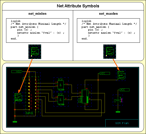
Figure 3-3: Net Attribute Definitions
This chapter describes how to use the Layout Editor, the Autorouter, the CAM Processor and CAM View for creating layout library symbols and designing PCB layouts and for generating and processing CAM output and manufacturing data for the PCB production. The examples presented in this chapter introduce the concepts and advanced features of the BAE PCB design system in a logical sequence and will take the user from the creation of layout library symbols and the design and modification of a PCB layout through to the generation of manufacturing data for the PCB production. The PCB design example is based on the circuit drawing and net list data prepared in the preceding chapters and will be subject to further processing in the following chapter. The reader should work through this chapter without missing any sections to gain full understanding of the BAE PCB design system. Once a command has been used and/or explained, the operator is assumed to have understood its function and be able to perform it again. Subsequent instructions containing this command will be less verbose for easier reading and more speedy learning.
| 4.1 | General |
| 4.1.1 | Components and Features |
| 4.1.2 | Starting the Layout System |
| 4.1.3 | Layout Editor Main Menu |
| 4.1.4 | Customized Layout Editor User Interface |
| 4.1.5 | In-built Layout System Features |
| 4.2 | Layout Library Symbol Design |
| 4.2.1 | Creating Layout Pads |
| 4.2.2 | Creating Layout Padstacks |
| 4.2.3 | Creating Layout Parts |
| 4.3 | Designing PCB Layouts |
| 4.3.1 | Creating and Editing PCB Layouts |
| 4.3.2 | Parts, Placement |
| 4.3.3 | Text and Graphic |
| 4.3.4 | Traces, Routing |
| 4.4 | Autoplacement |
| 4.4.1 | Part Set |
| 4.4.2 | Matrix Placement |
| 4.4.3 | Initial Placement |
| 4.4.4 | Placement Optimization |
| 4.5 | Autorouter |
| 4.5.1 | Starting the Autorouter |
| 4.5.2 | Autorouter Main Menu |
| 4.5.3 | Customized Autorouter User Interface |
| 4.5.4 | In-built Autorouter System Features |
| 4.5.5 | Autorouter Options |
| 4.5.6 | Autorouter Control |
| 4.5.7 | Autorouter Strategy |
| 4.5.8 | Autorouter Functions |
| 4.5.9 | Using the Autorouter |
| 4.6 | Special Layout Features |
| 4.6.1 | Batch Design Rule Check, Report |
| 4.6.2 | Color Setup, Color Tables, Pick Preference Layer |
| 4.6.3 | Layout Net List Changes |
| 4.6.4 | SCM Changes, Redesign |
| 4.6.5 | Defining and Editing Power Layers |
| 4.6.6 | Autorouter Via Keepout Areas |
| 4.6.7 | Area Mirror Mode |
| 4.6.8 | Automatic Copper Fill |
| 4.6.9 | Library Update |
| 4.6.10 | Back Net List |
| 4.6.11 | Blind and Buried Vias |
| 4.6.12 | Exiting the Layout System |
| 4.7 | CAM Processor |
| 4.7.1 | Starting the CAM Processor |
| 4.7.2 | CAM Processor Main Menu |
| 4.7.3 | Customized CAM Processor User Interface |
| 4.7.4 | In-built CAM Processor System Features |
| 4.7.5 | Plot Parameters |
| 4.7.6 | Power Layers |
| 4.7.7 | HP-GL Output |
| 4.7.8 | HP Laser Output |
| 4.7.9 | Postscript Output |
| 4.7.10 | Windows Generic Output |
| 4.7.11 | Bitmap Plot Output to Windows Clipboard |
| 4.7.12 | Gerber Photoplot |
| 4.7.13 | Drill Data |
| 4.7.14 | Insertion Data |
| 4.8 | CAM View |
| 4.8.1 | Starting the CAM View Module |
| 4.8.2 | CAM View Main Menu |
| 4.8.3 | Customized CAM View User Interface |
| 4.8.4 | In-built CAM View System Features |
| 4.8.5 | Processing Gerber Data |
| 4.8.6 | Processing Drilling and Milling Data |
| 4.8.7 | Retrieving Layouts from Gerber Data |
| Tables |
| 4-1 | Autorouter Grids |
| 4-2 | Autorouter Strategy Parameters |
| 4-3 | Pick Preference Layer Color Tables and Short Layer Names |
| 4-4 | Gerber Aperture Table "standard" |
| Figures |
| 4-1 | Layout Library Symbols |
| 4-2 | Layout with Board Outline and Plot Markers |
| 4-3 | Layout Library Access |
| 4-4 | Layout with Part Placement |
| 4-5 | Routing with or without Via Offset |
| 4-6 | Routing Traces Ongrid/Offgrid |
| 4-7 | Layout after Autorouting |
| 4-8 | Automatic Copper Fill Complexity |
| 4-9 | Layout with Filled Copper Areas |
| 4-10 | CAM Mirror Modes |
| 4-11 | CAM Power Layer Isolation |
The Bartels AutoEngineer PCB layout system essentially consists of an interactive Layout Editor with integrated layout symbol editor and functions for automatic part placement and automatic copper fill, the Bartels AutoEngineer for fully automated PCB routing, and CAM Processor and CAM View program modules for generating and processing CAM output and manufacturing data for PCB production. The following sections of this manual describe in detail how to use these modules.
The floating point database used throughout the BAE Layout Editor allows for the mixed specification of metric and imperial coordinate units. All placement coordinates including rotation angles can be specified with floating point values. There are no restrictions at the definition and placement of pads, copper areas, parts, traces, texts, etc. The user interface provides a genuine display even for the more complex structures such as circles or arcs. Area visibility can be defined according to mirror modes, thus supporting SMD pins with different pad shapes for component and solder side.
The Design Rule Check (DRC) operates in grid-free mode with a precision of eight digits behind the decimal point. The DRC provides constant monitoring of copper against net list, with visual indication of distance violations and short-circuits. The system supports both Online and Batch DRC. Online DRC performs incremental checks, i.e., only the modified items are checked real-time thus saving a lot of computation time.
The facilities allow to use the Layout Editor without fear of causing damage. Up to twenty commands can be reversed or undone by applying the function and then reprocessed with the function. ensures data security and provides a powerful feature for estimating design alternatives.
Arbitrary parts of the layout can be selected to groups and then moved, rotated, mirrored, copied or saved (and subsequently used as templates).
Fast interactive part placement with instant connections update guarantees an optimum exploitation of the layout area. Part connections (unroutes, airlines) are dynamically calculated and instantly displayed during placement. Parts can be rotated at arbitrary angles, and they can be mirrored for SMT applications. Parts can be placed at arbitrary coordinates and polar coordinates are supported for placing parts on a circle. The part library supports part-specific preferences for part rotation and part mirroring. During manual placement, an alternate package type can be selected for the currently processed part.
The system supports genuine net-orientated Connectivity. This means that electrical connections can be realized through copper areas instead of traces connecting. Traces and copper areas can be created in grid-free mode with floating point precision. Highlight is used to indicate the selected and/or processed signal, and each point of the signal can be connected. The system also supports arc shaped traces as well as blind and buried vias with automatic via type selection.
The BAE layout system provides powerful automatic copper fill functions. Copper areas can optionally be generated with line or cross hatching. The BAE layout system also supports power layer definitions. Arbitrarily shaped active copper areas can be placed on power layers, thus featuring split power planes.
High frequency and analogous applications are supported by useful facilities for shrinking and/or enlarging copper areas at arbitrary expansion values. Trace segment lengths and copper area edge lengths can automatically be determined or measured for test or documentation purposes.
With the Bartels User Language integrated to the Layout Editor the user is able to implement enhanced CAD functions and macros, user-specific post processors, report and test functions, etc. User Language programs can be called by applying the function from the menu or by pressing a key on the keyboard (hot key).
The BAE layout system is equipped with powerful
Autoplacement functions.
Parts can be selected and/or deselected for automativ placement according to set principles either by specifying part names
(c1,
r2,
ic15, etc.) or by specifying library symbol names
(dil14,
so20,
plcc44, etc.), where wildcards are also permitted. The user can also select parts from certain blocks of a hierarchical circuit design. The functions for designating the parts to be placed are a useful feature for controlling the placement process in a way that e.g., first the plug(s) can be placed, then the DIL packages, then the capacitors, etc.
The matrix placement facilities are used for the automatic placement of selectable part sets to definable placement grids. Matrix placement is intended especially for the initial placement of homogeneous part types such as memory devices, block capacitors, test points, etc. Of course the matrix placement function also considers the default rotation angle and mirror mode settings.
Initial placement functions are provided for performing a complete placement by automatically placing not yet placed parts inside the board outline. The parts are placed onto the currently selected placement grid, where pre-placed parts such as plugs and LEDs are considered as well as the connectivity derived from the net list. The initial placement algorithm features automatic SMD and block capacitor recognition. The solder side can optionally be used for placing SMDs. Parts are automatically rotated in 90 degree steps, where part rotation can optionally be restricted to provide fault-robust insertion data. A part expansion parameter can be set to support automatic part spacing. The initial placement process is controlled by adjustable heuristic weight factors for evaluating part segment fitting and for considering different net list structures. Intermediate rip-up/retry passes are activated during initial placement to optimize board area exploitation.
The system also provides placement optimization functions for automatic part and pin/gate swap. The part swap facility mutually exchanges identical components at their insertion position to minimize unroutes lengths. The pin/gate swap facility analogously performs an iterative exchange of gates and/or pins and pin groups, where gates or groups can also be swapped between different parts. Fixed parts are excluded from placement optimization. The admissibility of pin/gate swaps is fairly controlled with appropriate library definitions. Either single pass or multi pass optimization can be applied, with the swap method (only part swap, only pin/gate swap or both part and pin/gate swap) to be selected as required. Applying placement optimization will usually cause a significant simplification of the routing problem, thus resulting in a considerable time saving at the subsequent Autorouting process.
The Bartels Autorouter® is the culmination of years of research and practical routing experience. It has an impressive set of features and has the flexibility to route a wide range of PCB technologies, including analog, multilayer and SMT designs. The Bartels Autorouter® has been incorporated in leading PCB layout systems throughout the world, setting new industrial standards of success, reliability and flexibility and dramatically reducing the requirement for manual routing in all boards. Its incorporation into other systems has varied considerably. With Bartels AutoEngineer, all of the advanced features and capabilities of the Bartels Autorouter® are available. With the Bartels Autorouter®, an experienced BAE user should be able to complete the design of a eurocard PCB including schematic drawing and manufacturing data output in not more than one or two days.
Bartels Autorouter® is based on special backtracking/rip-up/reroute algorithms. These types of routing algorithms have been proven to be the only ones capable of achieving 100% route completion on the majority of today's challenging PCB designs. Extensive artificial intelligence features have been built into the router to produce high quality design results in a reasonable time. The Bartels Autorouter® includes special features for production optimization giving excellent yield in board manufacture. The complete routing process is supervised by a backtracking algorithm, which not only prevents from a deterioration of the result or a dead-lock during rip-up or optimization but also is able to exploit a new and/or better routing solution.
Both the selective rip-up and the cross-net optimizer passes are assisted by a unique intelligent multi-net cleanup algorithm with pattern recognition. This algorithm identifies traces blocking unrouted connections and rips up and reroutes multiple connections or even trees at a time to improve the global routing result. The Autorouter is capable of moving trace bunches to make space for not yet routed connections (push'n'shove routing). Cleanup passes for performing cross-net changes are applied during optimization and will considerably reduce via counts and straighten trace paths. All advanced routing features are supported by a sophisticated array of heuristic cost parameters which are dynamically adapted to produce quality routing results comparable to those made by skilled layout designers.
The Bartels Autorouter® is capable of simultaneously routing up to 28 layers (16 signal layers and 12 power layers; multilayer routing). The Autorouter automatically identifies and connects pre-placed power supply structures thus ensuring correct power and ground routing. The router also utilizes automatic routines for correctly connecting SMD pins to power layers wherever necessary. This feature also supports any split power planes placed on the power layers (split power plane routing). Routing widths are pin-specific rather than net-specific. SMD pins are routed with the anticipated pin routing widths to avoid perpendicular positioning of SMD parts during the soldering process. T-shaped connections are automatically generated (full copper sharing).
The routing progress can be watched both graphically and on statistical readout on the Autorouter user interface. The Autorouter can be stopped at any time and then continued or re-started with changed parameters on demand.
Features are provided for automatically adapting layouts to placement and/or net list changes (re-entrant routing) where the Autorouter evaluates pre-routed traces, identifies and removes wrong and redundant paths, and then routes open connections to achieve a correct 100% solution. Subsequently, the modified layout can be optimized again.
All of today's advanced PCB technologies are fully supported by the Bartels Autorouter®. The Autorouter is able to consider and/or connect arbitrarily shaped pads, traces, copper areas, power planes and keepout areas. The built-in off-grid recognition allows off-grid placement of parts and pre-routed traces. The Autorouter supports standard routing grids with optional half-grid routing (1/20 inch to 1/100 and/or 1/200 inch), arbitrary routing grids for special pin pitches and grid-free routing. Multilayer SMD technologies are supported by the Autorouter's SMD via preplace and BGA (Ball Grid Array) fanout routing algorithms, which can optionally be used if via pre-allocation is required for connecting SMD and/or BGA pins to inside layers with high priority. The Bartels Autorouter® supports microvias (via-in-pad technology) and blind and buried vias with automatic via type selection thus increasing the routability of multilayer layouts and also supporting new PCB manufacturing technologies such as processes for producing plasma-etched vias. Area and block routing methods can be supported by defining keepout routing areas and/or prohibited layers, and the Autorouter is capable of considering via keepout areas.
The Autorouter provides the same initial placement and placement optimization functions as already known from the Layout Editor, allowing for automatic pre-placement and placement optimization before starting the autorouting process.
The Autorouter provides enhanced routing features such as placement optimization (pin/gate swap) during rip-up/retry routing, gridless routing, single net routing, component routing, area routing, mixed-grid routing, etc. The place and route function activates both the (including complete initial placement and placement optimization) and the (including complete , rip-up/retry routing and optimizer), thus performing complete placement and routing on the push of a button. The single net routing function of the Autorouter is used for automatically routing selectable nets and/or connections. The single net router can be applied to pre-rout power supply or critical nets with specific preferences for trace widths, clearance, layer assignments, etc. For completeness reasons the single net router also supports an option for selectively deleting already routed nets and/or connections. The Autorouter provides a feature for selectively routing net groups (e.g., busses of a certain circuit block) using specific routing options for preferred routing directions, trace widths, etc. The component routing function can be used to rout selectable parts. The area/block routing function of the Autorouter is used for routing selectable areas and/or circuit blocks. It is possible to define different routing areas according to circuit topology (I/O, memory, digital and/or analog part of the design, etc.) and perform autorouting using block-specific routing options such as routing grid, clearance, preferred routing direction, bus routing preferences, etc. During the rip-up autorouting process the Autorouter utilizes features for automatically performing selective component and/or pin/gate swaps in cases where this might result in better routability of swapped parts, gates or pins.
The facilities allow to use the Autorouter without fear of causing damage. Up to twenty commands can be reversed or undone by applying the function and then reprocessed with the function. Since this is true even for most complex operations such as complete Autorouter passes, ensures data security and provides a powerful feature for estimating design alternatives.
With the Bartels User Language integrated to the Autorouter, the user is able to implement enhanced CAD functions and macros, user-specific placement and autorouting procedures, report and test functions, etc. User Language programs can be called by applying the function from the menu or by pressing a key on the keyboard (hot key).
The Autorouter module of the BAE HighEnd system provides advanced autorouting technologies based on patented neural network technology (Neural Autorouter). The BAE HighEnd Autorouter supports skilled analog signal routing, automatic microwave structure generation, grid-less object-orientated routing with automatic placement optimization, etc. The BAE HighEnd Autorouter also provides features for routing problem recognition and/or classification and for learning and automatically applying problem-adapted routing strategies and/or rules.
The Bartels AutoEngineer layout system allows for the definition and creation of arbitrarily shaped areas and pads which can also be rotated at any angle. All these features are supported by the intelligent CAM Processor, which utilizes a series of automatic fill algorithms with multiple aperture selection and area reduction. I.e., pad definitions are not necessarily restricted to some particular tool set, but may fully support the demanded technology. The CAM Processor automatically optimizes the use of the selected tools and aperture table definitions to generate all structures at highest possible precision with regard to the chosen plot parameters and output tolerance ranges. The system also provides appropriate error messages and highlight features to indicate objects which cannot be plotted using the selected tools and the current plot parameter settings. In-built functions are available for producing HP-GL pen plot, PCL laser print and Postscript output, and for supporting configurable drivers for Gerber photoplotting with freely definable aperture tables. The CAM Processor also provides programming data for auto insertion and pick and place equipment, solder mask, drill data and SMD adhesive masks. CAM output is generated considering general parameters such as tool tolerance, scaling factor, CAM rotation and/or mirroring, freely definable CAM origin, etc. Special plot parameters for generating negative power layer and split power plane plots are also supported. With the flexibility of easily preparing all of the required output data the BAE user has free choice amongst photo plot producers and PCB manufacturers.
With the Bartels User Language integrated to the CAM Processor the user is able to implement enhanced CAM functions and macros, user-specific and/or batch-driven post processors, report and test functions, etc. User Language provides unrestricted access to the BAE design database. The user is able to implement user-specific programs for exporting any data such as part lists, net lists, geometry data, drill data, insertion data, test data, milling data, etc. in freely definable formats. User Language programs can be called by applying the function from the menu or by pressing a key on the keyboard (hot key).
The CAM View module provides features for displaying Gerber data, drilling data (Sieb&Meier and/or Excellon) and milling data (Excellon) in order to check CAM data validity and to estimate the efficiency of tool usage. CAM View features multiple input and sorted output with variable offsets and adjustable aperture tables to support panelization. CAM View also provides a powerful function for translating Gerber data to BAE layout design data, i.e., with CAM View the user is able to import Gerber data produced by foreign PCB layout systems.
With Bartels User Language integrated to the CAM View module the user is able to implement enhanced CAM View functions and macros, user-specific batch procedures, report and test functions, etc. User Language programs can be called by applying the function from the menu or by pressing a key on the keyboard (hot key).
It is recommended to start the Bartels AutoEngineer from the directory where the design files should be generated since this considerably simplifies job file access. If you intend to process the examples provided with this manual it is recommended to move to the BAE examples directory installed with the BAE software. The Layout Editor can be called from the Bartels AutoEngineer main shell. Start the BAE shell by typing the following command to the operating system prompt:
> bae
The AutoEngineer comes up with the Bartels logo and the following menu (the function is only available under Windows/Motif; the and menu items are available only with special software configurations such as BAE HighEnd or BAE IC Design):
| Schematic |
| Layout |
| [ IC-Design ] |
| Packager |
| CAM-View |
| [ Setup ] |
| [ Next Task ] |
| Exit BAE |
Move the menu cursor to the menu item and confirm this choice by pressing the left mouse button:
| Layout |
The Layout Editor program module is loaded and the Layout Editor menu is activated. Check your BAE software installation if this fails to happen (see the Bartels AutoEngineer® Installation Guide for details on how to perform a correct installation).
It is also possible to call the Layout Editor directly from the Packager. In this case, layout element creation for the net list created by the Packager is automatically suggested for designs not yet containing a corresponding layout.
The Layout Editor standard/sidemenu user interface provides a menu area on the right side, consisting of the main menu on top and the currently active menu below that main menu. After entering the Layout Editor the menu is active and the menu cursor points to the function.
The Windows and Motif versions of the
Layout Editor can optionally be operated with a pull-down menu user interface providing a horizontally arranged main menu bar on top. The
WINMENUMODE command of the
bsetup utility program is used to switch between
SIDEMENU and
PULLDOWN Windows/Motif menu configurations (see
chapter 7.2 for more details).
The following main menu is always available whilst processing layout elements with the Layout Editor:
| Undo, Redo |
| Display |
| Files |
| Parts |
| Traces |
| Areas |
| Text, Drill |
| Groups |
| Parameter |
| Utilities |
The functions provided with the menu allow you to use the Layout Editor without fear of causing damage. Up to twenty commands can be reversed or undone using and then reprocessed with the . This is true even for complex processing such as group functions or User Language program execution. ensures data security and provides a powerful feature for estimating design alternatives.
The or menu can either be activated by selecting the corresponding main menu item or by pressing the middle mouse button. Activation through the middle mouse button is even possible whilst performing a graphical manipulation such as placing or moving an object. The or menu provides useful functions for changing display options such as zoom window, zoom scale, input and/or display grids, grid and/or angle lock, color settings, etc. The or menu also contains advanced display functions such as and .
The menu provides functions for creating, loading, saving, copying, replacing and deleting DDB elements. The menu also allows to load and/or store color tables or to call important database management functions such as listing DDB file contents and performing library update.
The provides functions for defining part placement groups, for manual part placement, for part renaming, for automatic part placement (matrix placement, initial placement) and for manual and automatic placement optimization (component swap, pin/gate swap). The function for selecting the via(s) for subsequent routing is also provided in this menu.
On part level, the menu is used for placing, moving, deleting and renaming pins (i.e., padstack symbols). On padstack level, the menu is used for placing, moving and deleting pads.
The menu provides functions for interactive routing, i.e. for manually creating new traces and for modifying or deleting existing traces and/or trace segments.
The menu is used for defining the board outline, for generating copper areas and power planes and for creating documentary lines and/or documentary areas. Existing areas can be moved, rotated, mirrored, copied and deleted. The menu also provides the copper fill functions for defining copper fill workareas, for automatic copper fill area generation and/or elimination and for hatched copper area creation.
The menu is used for creating, moving, changing and deleting texts on any layout hierarchy level. On padstack level, the menu provides additional functions for defining drill holes.
The menu provides functions for selecting elements to group, for moving, rotating, mirroring, scaling, copying, deleting, fixing, releasing, saving and loading groups, and for replacing symbols in a group.
The menu provides functions for selecting the layout library, setting the origin and the element boundaries of the currently loaded element, defining power layers, selecting the mincon function for the airline display, setting the spacing design rule parameters and activating the automatic design data backup feature.
The menu provides functions for exiting BAE, returning to the BAE main shell, calling the Autorouter or the CAM Processor, starting the batch design rule check, generating net list data from current copper (), defining area mirror visibility and starting User Language programs.
The BAE software comes with User Language programs for activating a modified Layout Editor user interface with many additional functions (startups, toolbars, menu assignments, key bindings, etc.). The bae_st User Language program is automatically started when entering the Layout Editor. bae_st calls the uifsetup User Language program which activates predefined Layout Editor menu assignments and key bindings. Menu assignments and key bindings can be changed by modifiying and re-compiling the uifsetup source code. The hlpkeys User Language program is used to list the current key bindings. With the predefined menu assignments of uifsetup activated, hlpkeys can be called from the function of the menu. Menu assignments and key bindings can be listed with the uifdump User Language program. The uifreset User Language program can be used to reset all currently defined menu assignments and key bindings. uifsetup, uifdump and uifreset can also be called from the menu of the keyprog User Language program which provides additional facilities for online key programming and User Language program help info management.
Pressing the left mouse button in the graphic workarea activates a context-sensitive menu with specific functions for the object at the current mouse position if no other menu function is currently active. The and/or file management functions are provided if no element is currently loaded. This feature is implemented through an automated call to the ged_ms User Language program.
The Windows and Motif pulldown menu user interfaces of the Layout Editor provide facilities for cascading submenu definitions. I.e., submenus can be attached to other menu items. The uifsetup User Language program configures cascading submenus for the pulldown menu interfaces of the Windows/Motif Layout Editor modules. This allows for easy submenu function location (and activation) without having to activate (and probably cancel) submenus. The function repeat facility provided through the right mouse button supports cascading menus to simplify repeated submenu function calls.
The following Windows/Motif parameter setup dialogs are implemented for the Layout Editor:
The uifsetup User Language program replaces the parameter setup functions of the Windows and Motif pulldown menus with the above menu functions for activating the corresponding parameter setup dialogs.
When using pulldown menus under Windows and Motif, the uifsetup User Language program configures the following modified Layout Editor main menu with a series of additional functions and features:
| File |
| Edit |
| View |
| Parts |
| Traces |
| Areas |
| Text, Drill |
| Settings |
| Utilities |
| Help |
The Layout Editor provides an in-built feature for automatically saving important design and operational parameters with the currently processed SCM sheet and/or SCM library hierarchy level. The following parameters are stored to the current design file when activating the function:
Parameter sets are stored with special names according to the currently processed layout database hierarchy level. The layout element name is used for layout elements, parameter set name
[part] is used for layout part symbol elements,
[padstack] is used for layout padstack elements and
[pad] is used for layout pad elements. When loading an element, the corresponding parameter set is automatically loaded and/or activated as well, thus providing a convenient way of activating a default parameter set suitable for processing the selected design and/or library element type.
The layer assignment is most important for the creation and modification of layout symbols and for the design of layouts. The system provides the following layers and/or display items:
The signal layers are subject to the design rule check. On the signal layers the electrical conductivity of the PCB is defined by creating and/or placing traces, pads and passive or active copper areas. , and are special signal layers.
The can be dynamically assigned to a certain signal layer during the layout design process. On default, the is assigned to signal layer 2. The is most useful when generating library symbols for multilayer designs with an arbitrary number of layers. The function from the menu is used to assign the PCB top layer, thus defining the number of PCB layers. The mirror functions (e.g., for mirroring parts) will always consider the current top layer setting, i.e., signal layers beyond the top layer are not affected by mirror functions.
Note that the menu item text for selecting the can be changed with the BAE setup to provide a user-specific menu text such as or . See the description of the bsetup utility program for more details on customizing the layout signal layer menus.
The signal layer includes all signal layers from signal layer 1 (solder side) to the currently defined top signal layer (component side). Objects defined on are considered to be placed on all signal layers and are checked and plotted accordingly. The signal layer is most useful for the definition of library symbols such as drilled pins with identical pad shapes on all signal layers.
The signal layer matches all signal inside layers, i.e., the signal layer includes all layers between signal layer 1 (solder side) and the currently defined top signal layer (component side). Objects defined on are considered to be placed on all signal inside layers and are checked and plotted accordingly. The signal layer considerably simplifies pin definitions for multilayer layouts where inside layer pad shapes differ from component and solder side pad shapes.
Up to twelve power layers can be defined with each layout, all of which being negatively displayed and plotted by the system. The
function from the
menu is used to assign power layer signal names such as
gnd,
0v or
vcc to define the power layers of the currently loaded layout. The
Layout Editor allows for the DRC-controlled definition of split power planes by (hierarchically) placing active copper on power layers. The
CAM Processor automatically generates isolations and heat traps when plotting power layers.
The documentary layers are used to store and/or include documentary information (graphic, text) and special keepout definitions with the layout and/or the layout library symbols. The bsetup utility program can be used to define up to 100 different (or 12 in BAE Professional simultaneously accessible) documentary layers with individual names and characteristics according to special requirements. The system allows for the definition of customer-specific documentary layers for, e.g., silk screen, insertion data, solder resist, glue spots, drill plan and drill overlap control, plot markers, part spacing check, comments, measuring, etc. Each documentary layer consists of the following sides to support double-sided SMD design:
| Side 1 |
| Side 2 |
| Both Sides |
Each documentary layer side is a sub-layer of the corresponding documentary layer. The and sub-layers are mutually interchanged when performing mirroring. The CAM Processor can optionally plot the sub-layer together with and/or . Documentary layer definitions have fundamental influence on what can be defined in the layout and which CAM output can be produced. Documentary layer definition changes introduced by bsetup only apply to subsequently defined library symbols to enable data exchange between different configurations. It is strongly recommended to become familiar with the features for defining documentary layers (and to define documentary layers according to your specific requirements) before starting with the design of real layouts or layout symbols for productive use. See chapter 7.2 of this manual for a description of the bsetup utility program and for the default documentary layer definitions provided with initial BAE software installations.
The layer is used for defining and/or displaying the board outline of the currently loaded layout. The layer is used for displaying unroutes on the currently loaded layout. The layer is used for displaying drill holes on the currently loaded layout, part or padstack. , , and are layers for displaying special layout user interface elements. The layers are used for assigning colors to drill classes. The and layers are used for the selection of patterns for the display of fixed and/or glued layout elements.
The pick preference layer is used to resolve ambiguities when selecting objects which are placed at the same position but on different layers (e.g., traces, areas, SMD parts, etc.). The pick functions use the pick preference layer to designate the element to be selected, if more than one object of interest is placed at the pick position. The pick preference layer can be selected with the function from the menu. On default, the pick preference layer is set to signal layer 1 (solder side).
The dialog from the menu provides the parameter for selecting the element pick method for multiple elements at the same pick position. The default option picks an element from the currently selected preference layer. The option provides an element selection facility if more than one element is found at the pick position. A loop for highlighting the selectable elements with status line short description is activated. The highlighted element can be selected through return key or left mouse button click. This element selection can be aborted through escape key or right mouse button input. Any other key switches to the next element at the pick position.
A net list is usually required for the layout design. In BAE, the net list is commonly created with the Schematic Editor and will then be transferred to the layout using the Packager. Alternatively, ASCII net lists can be imported to the BAE layout system using utility programs such as conconv or redasc. See chapter 3.4 of this manual for more details on net list processing.
The function for loading a layout will not only load the pertinent data from the lower hierarchy levels (parts, padstacks and pads), but also the corresponding net list. The net list data is correlated with all geometrical data on the layout ("Connectivity Generation"). Please note that the element names for both the layout and the net list must be identical for this to work.
After successfully generating the connectivity, the system is capable of instantly controlling and/or correlating each layout modification with the net list definitions. This high-sophisticated layout design feature is called "Full Copper Sharing" or "True Connectivity". Full copper sharing enables real-time recognition of electrical connections, no matter whether connections are created with traces, copper areas or vias. I.e., the system supports advanced routing features such as cross connection recognition, genuine T-connections, lining up traces created with group copying, implementing routes with arbitrarily shaped copper areas, etc.
The BAE HighEnd layout connectivity evaluation system uses special data structures for storing additional information about the structure of electric connections between copper elements. This requires more memory compared to BAE Professional, but results in dramatically shortened response times when manually editing large nets or moving parts since only the elements in the neighborhood of the currently processed object have to be considered by the DRC.
Not yet routed connections (unroutes) are displayed as airlines. During part placement, the function performs dynamic (real-time) recalculation of these airlines in order to display minimum length airline sets. This makes the function an indispensable utility for achieving an optimum placement. The menu item from the menu is used to set the type of airline display, i.e., to choose the method of calculating unroutes from pin-to-pin or corner-to-corner minimization where also the unroute components to be calculated can be selected (horizontal only, vertical only, horizontal + vertical sum, etc.).
BAE HighEnd utilizes modified data structures for internal connectivity representation and airline calculations. The BAE HighEnd functions run at much higher performance compared to BAE Professional, however, at the cost of higher memory requirements.
The BAE design rule check utilizes full copper sharing features to perform real-time recognition of open connections, short-circuits and distance violations. Open connections (unroutes) are displayed as airlines, short-circuits are indicated with highlight, and distance violations are enclosed by a rectangle. The corresponding colors for displaying , and can be selected with the function from the menu.
Only modified items are checked real-time by the incremental online design rule check, thus saving a lot of computing time. As board parameters could have changed until post-processing, it is recommended to use the function from the menu for a final batch design rule check with the current layout parameter settings before releasing the board. The incremental connectivity, however, does not have parameters and thus is always correct. The function from the menu should be used after to check all error counts.
The spacing parameters for the distance checks can either be set from the
menu (functions
,
and
) or can be defined as net-specific parameters in the net list using the
MINDIST net attribute). Note, however, that these parameter settings need not be the same as for the autorouting since the
Autorouter can automatically set minimum distance parameters according to the routing grid selection. Net-specific spacing parameters are individually considered by the
Autorouter.
The Layout Editor group functions provide powerful features for design data manipulation. An arbitrary set of items of the currently loaded layout or part can be selected to a group which then can then be saved, moved, rotated, mirrored, scaled, copied, deleted, fixed or unfixed.
The group functions are featuring set principles. Elements can be added (selected) to or removed (deselected) from the currently defined group. Highlight display is used to indicate group-selected items. The function is used to select and/or deselect parts, traces, areas, texts, visible and/or invisible elements or elements of any type by defining an area around the items to be selected. The function is used to select and/or deselect single elements of a certain type (part, trace, area or text) by picking the desired items. The function is active as long as valid pick elements are selected, thus allowing for the selection of a series of objects of a certain type). The function is used to deselect all items from the current group.
All group-selected elements are subject to subsequent group functions such as , , and . The and functions only work on group-selected parts, traces and vias.
The number of modified elements is displayed with the feedback messages of , , , and functions. This information can be used to check whether the group function was applied as intended.
The function is used to save the currently defined group. The function prompts for a group origin selection which becomes the origin of the new element> The group origin is also used as the reference point for group load commands. Saved groups are stored as an element of the same type as that from which the group was selected. To prevent from unintentionally overwriting existing database elements, prompts for confirmation if the specified element already exists in the destination file. The function can be used to reload previously saved groups (as well as layout and/or part elements) to different layouts and/or parts. The save and load group facilities can be used for a variety of tasks such as replicating tracking, saving and loading PCB templates, stealing from existing and proven designs, etc.
The
and
functions do not perform automatic part and/or pin renaming when copying and/or loading groups including parts (on layout level) or padstacks (on part level). Naming conflicts are resolved by assigning
# names to parts and/or pins, and manual renaming is required to correct the name list (or some special
User Language program must be implemented for solving such name list problems automatically).
Pressing the right mouse button during group movement operations such as , or activates a submenu with functions for placing the group to relative or absolute coordinates (, ), rotating the group (, , ), mirroring the group (around the X-axis using either and/or ) or even scaling the group element dimensions and placement coordinates (, applied after placing the currently processed group). The submenu provides the option for automatically rerouting traces between the moved group and the rest of the layout after selecting the start point for the group move operation. first expects an interactive selection of a quadrant origin and then prompts for the quadrant (Upper Right, Upper Left, Lower Left, Lower Right). Subsequent group move operations are only applied on group-selected elements and/or points placed within the selected quadrant. It is possible to move parts of a layout and to reroute the connections to the moved group. Note, however, that the algorithm applied by the group move functions for rearranging traces is not a genuine routing algorithm and is designed to be applied on horizontal and/or vertical move operations only. For more complex group shift operations it is recommended to discard the routing and perform a re-routing using the appropriate Autorouter procedures.
The function first resets the currently defined group to deselect all group elements before performing the load operation. After successfully loading a group, all loaded group elements are automatically group-selected. I.e., only loaded group elements are subject to subsequent group functions.
The Layout Editor supports different options for displaying group-selected elements during group movement operations. The behavior of this feature can be controlled with the function which provides the following display modes:
| Groups |
| Display Mode |
| Moving Picture Off |
| Display Layer Only |
| Moving Picture On |
| Moving Picture All |
deactivates the group movement display.
displays upper level group-selected elements which are assigned to the group display layer; the group display layer is a BAE setup parameter defined with the
LAYGRPDISPLAY command of the
bsetup utility program (see
chapter 7.2 for a description of
bsetup).
displays all group-selected elements except for traces, vias and drill holes during group movement.
displays all group-selected elements including traces, vias and drill holes during group movement.
is the default setting.
The function is used to replace group-selected part macros (on layout level) or padstack macros (on part level). This function is most useful for fast pin type replacement (technology change) on part level. On layout level, the function supports alternate part package type assignments for net list parts which include the specified part macro in their alternate part package type list. Package types for non-netlist parts, however, are changed without this check.
Certain layout elements such as parts or traces can be fixed. Fixed objects are not changed by subsequent automatic processes such as placement optimization, automatic pin/gate swap or autorouting. It is strongly recommended to fix critical elements such as parts (e.g., plugs, switches, LEDs, etc.) which are to be excluded from the placement optimization or manually pre-routed traces (e.g., for power supply) which must not be changed by the Autorouter. A specific highlight for indicating fixed elements is activated during fix and release operations.
All functions for manipulating and/or copying fixed elements (parts, traces, vias) preserve and/or copy existing fixed modes. This also means that the Layout Editor trace functions for interactive routing keep traces fixed flags when processing pre-routed fixed traces. I.e., when manipulating pre-routed fixed traces, there is no need of re-fixing such traces to prevent the Autorouter from re-routing and/or rejecting pre-routed traces.
In the Layout Editor, the functions from the menu are used to create and/or modify polygons and/or pad shapes. Each polygon definition is associated with a layer and/or a polygon type and can contain an arbitrary number of arcs. The definition of an arc is applied by selecting either the or the option from the submenu to be activated after specifying the arc start point; subsequently, the system expects the arc center point specification, and the arc definition is completed with the arc end point selection. The system provides instant display of the resulting circle and/or arc during interactive input of the arc center and end points. At the definition of full circles, the input of the arc end point is superfluous, i.e., the full circle definition can be completed with the submenu function to be activated after setting the arc center point.
The algorithm for picking polygon corners and polygon segments picks the polygon element with minimum distance from the pick point if more than one possible pick element is within snapping distance. This allows for reliable selection of polygon elements even when working in (small) zoom overview display modes.
The
$pltfname (element file path name),
$pltfsname (element file name) and
$pltename (element name) texts can be placed to display the project file path name, the project file name (without directory path) and the element name of the currently loaded element.
The
$plttime (current time),
$pltdatede (current date, German notation) and
$pltdateus (current date, US notation) system attributes are substituted with the current time and/or date when displayed and/or plotted on layout level.
The
$pltstime (save time),
$pltsdatede (save date, German notation) and
$pltsdateus (save date, US notation) system attributes are substituted with the time and date at which the currently loaded layout was last saved.
Automatic time and date substitutions are applied throughout all database hierarchy levels (pad, padstack, part, layout), unless other attribute values are explicitly set for these attributes.
The
Layout Editor automatically activates a measuring function when placing new text with the hash character as text string
(#). This measuring function determines the distance between the two input coordinates subsequently to be specified. The resulting text string is built from the corresponding distance value with length units (inch or mm) retrieved from the current coordinate display mode as selected with the
function from the
menu.
The Layout Editor supports the definition of arbitrarily shaped areas and pads which can also be rotated at any angle. All these features are supported by the intelligent CAM Processor, which utilizes a series of automatic fill algorithms with multiple aperture selection and area reduction. The CAM Processor automatically optimizes the use of the selected tools and aperture table definitions in order to generate all structures at highest possible precision with regard to the chosen plot parameters and output tolerance ranges. The system also provides appropriate error messages and highlight to indicate objects which cannot be plotted using the selected tools and the current plot parameter settings.
As mentioned above, the CAM Processor is able to construct arbitrary polygons. When defining pads, consideration should, however, be given to the way in which Gerber photo plot data is generated. A flash code containing only one set of coordinates is used for areas that match apertures such as circles and squares. For areas that don't match apertures efficient drawing techniques generating few coordinates are used where possible (e.g., with rectangles), but with some shapes and sizes much more coordinates are needed. With careful design of pads and appropriate aperture tables and plot parameter settings, much smaller Gerber data files can be generated, making them quicker to copy, cheaper to send by modem, less expensive to plot and require less media space, thus considerably reducing the costs incurred by the CAM and manufacturing process.
The Bartels User Language Interpreter is integrated to the Layout Editor, i.e., User Language programs can be called from the Layout Editor, and it is possible to implement any user-specific Layout Editor function required such as status display, parameter setup, reports and test functions, CAD/CAM input/output functions, symbol library management utilities, automatic or semi-automatic placement and/or routing functions, customer-specific batch procedures, etc.
The
Layout Editor provides both explicit and implicit
User Language program call facilities.
User Language programs can be started with explicit program name specification using the
function from the
menu (empty string or question-mark
(?) input to the program name query activates a
User Language program selection menu).
User Language programs can also be called by simply pressing special keys of the keyboard. This method of implicit User Language program call is supported at any time unless another interactive keyboard input request is currently pending. The name of the User Language program to be called is automatically derived from the pressed key, i.e. pressing a standard and/or function key triggers the activation of a User Language program with a corresponding name such as ged_1 for digit key 1, ged_r for standard key r, ged_# for standard key #, ged_f1 for function key F1, ged_f2 for function key F2, etc.
The Layout Editor User Language Interpreter environment also features event-driven User Language program calls, where User Language programs with predefined names are automatically started at certain events and/or operations such as ged_st at Layout Editor module startup, ged_load after loading a design element, ged_save before saving a design element, ged_tool when selecting a toolbar item and ged_zoom when changing the zoom factor. The module startup User Language program call method is most useful for automatic system parameter setup as well as for key programming and menu assignments. The element save and load program call methods can be used to save and restore element-specific parameters such as the zoom area, color setup, etc. The toolbar selection event must be used to start User Language programs which are linked to toolbar elements. The zoom event can be used to apply an update request to a design view management feature.
Bartels User Language also provides system functions for performing key programming, changing menu assignments and defining toolbars. These powerful features can be applied for user interface modifications. Please note that a large number of additional functions included with the Layout Editor menu are implemented through the User Language programs delivered with the BAE software.
See the Bartels User Language Programmer's Guide for a detailed description of the Bartels User Language (chapter 4.2 lists all User Language programs provided with the BAE software).
A series of advanced Bartels AutoEngineer features are implemented through the integrated Neural Rule System. See chapter 6.3.2 for the rule system applications provided with the PCB layout system.
The
Bartels AutoEngineer is shipped with an extensive layout library. Nevertheless, you might require a certain layout symbol which has not yet been defined in these libraries. This section shows in detail how to create layout library symbols. The example symbols are created starting with the lowest DDB hierarchy level. I.e., first of all some pad and padstack symbols are defined, and, subsequently, some layout part symbols are defined. All these symbols will be stored to a DDB file named
demo.ddb. Use the following commands to move to the BAE examples directory (e.g.,
c:\baejobs) and start the
Bartels AutoEngineer:
> C:
The BAE main menu is activated, and you can start the Layout Editor with the following command:
| Layout |
The
Layout Editor is activated, and you can create layout library elements. You should become familiar with the conventions used for layout symbol design before generating your own symbols. Technology-dependent and manufacturing-specific conventions are usually to be considered with regard to pad shape definitions, part insertion pick points, identification of part pin
1, pin placement grids, part placement origin, minimum text sizes, drill symbols, part spacing parameters for SMDs, etc. The layer assignment is most important for the creation and modification of layout symbols and for the design of layouts in order to provide correct and complete CAM data output later (see
chapter 4.1.5 for more details).
Figure 4-1 shows the layout library symbols to be created in the following sections.
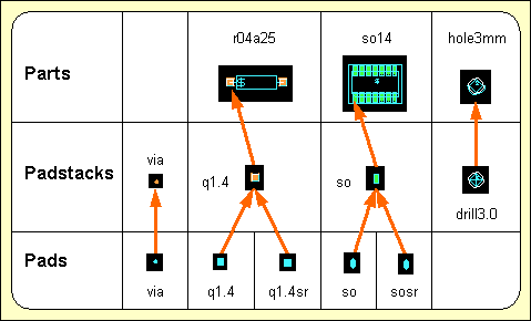
Figure 4-1: Layout Library Symbols
On layout pad level the pad shapes (i.e., the pin contact areas) are defined by creating passive copper areas. Different pad symbols can be assigned to different layers on a single padstack symbol thus defining a particular layout pin type.
It is recommended to refrain from assigning layers to the copper areas created on pad level, i.e., layer assignment should be disabled on pad level (this is the default setting introduced by bsetup). The layer assignment can later be applied on padstack level to minimize the expenditure for adapting layout libraries to different manufacturing technologies.
Use the following commands to create a new pad symbol named
via with an element size of 1*1mm in DDB file
demo.ddb:
| File |
| New |
| Pad |
| File Name ? | demo |
| Element Name ? | via |
| Element Width (mm/") ? | 1 |
| Element Height (mm/") ? | 1 |
The display now shows a square frame with a cross in the middle. The frame describes the element boundaries of the pad, and the cross marks the position of the element origin.
Use the following commands to define a circle-shaped copper area with a diameter of 0.9mm on the currently loaded pad element:
| Areas |
| Add Passive Copper |
| Jump Absolute |
| Absolute X Coordinate (mm/") ? | 0.45 |
| Absolute Y Coordinate (mm/") ? | 0 |
| Arc Left |
| Jump Absolute |
| Absolute X Coordinate (mm/") ? | 0 |
| Absolute Y Coordinate (mm/") ? | 0 |
| Done |
The pad symbol's element boundaries should be reduced to enclose the pad definition as densely as possible. This is accomplished with the following commands:
| Settings |
| Upper/Right Border |
| Jump Absolute |
| Absolute X Coordinate (mm/") ? | 0 |
| Absolute Y Coordinate (mm/") ? | 0 |
| Lower/Left Border |
| Jump Absolute |
| Absolute X Coordinate (mm/") ? | 0 |
| Absolute Y Coordinate (mm/") ? | 0 |
You can also place documentary information such as text, documentary lines or documentary areas on pad level. However it is recommended to refrain from placing documentary items on pad level since this would result in a very specific pad definition which could be used in quite few superior layout symbols. Use the following commands to save the pad symbol:
| File |
| Save Element |
Now the new pad symbol named
via is completely defined and stored to the DDB file
demo.ddb. This pad will later be loaded to a padstack thus defining a via for manual and automatic routing.
Use the following commands to define a pad named
q1.4 with a square-shaped copper area (edge length 1.4mm) in DDB file
demo.ddb:
| File |
| New |
| Pad |
| File Name ? | demo |
| Element Name ? | q1.4 |
| Element Width (mm/") ? | 2 |
| Element Height (mm/") ? | 2 |
| Areas |
| Add Passive Copper |
| Jump Absolute |
| Absolute X Coordinate (mm/") ? | 0.7 |
| Absolute Y Coordinate (mm/") ? | 0.7 |
| Jump Relative |
| Relative X Coordinate (mm/") ? | -1.4 |
| Relative Y Coordinate (mm/") ? | 0 |
| Jump Relative |
| Relative X Coordinate (mm/") ? | 0 |
| Relative Y Coordinate (mm/") ? | -1.4 |
| Jump Relative |
| Relative X Coordinate (mm/") ? | 1.4 |
| Relative Y Coordinate (mm/") ? | 0 |
| Done |
| File |
| Save Element |
With the commands above, a pad named
q1.4 has been defined which will be used on a padstack for parts with plated-through pins. This pin definition will require a corresponding pad symbol for the solder resist mask, which should be same as
q1.4 except for a slightly expanded copper area. Use the following commands to copy the (still loaded) pad named
q1.4 to a pad symbol named
q1.4sr (square 1.4mm, solder resist), then load pad
q1.4sr and enlarge the copper area of
q1.4sr by 0.1mm:
| File |
| Save Element As |
| File Name ? | |
| Element Name ? | q1.4sr |
| Load Element |
| Pad |
| File Name ? | |
| Element Name ? | q1.4sr |
| Areas |
| Resize Area |
| Move to Area Corner/Edge |
| Expansion Distance (mm/") ? | 0.1 |
| File |
| Save Element |
Use the following commands to define a pad named
so with a finger-shaped copper area (width 0.7mm, length 1.7mm) in the
demo.ddb DDB file:
| File |
| New |
| Pad |
| File Name ? | demo |
| Element Name ? | so |
| Element Width (mm/") ? | 1 |
| Element Height (mm/") ? | 2 |
| Areas |
| Add Passive Copper |
| Jump Absolute |
| Absolute X Coordinate (mm/") ? | 0.35 |
| Absolute Y Coordinate (mm/") ? | 0.5 |
| Arc Left |
| Jump Relative |
| Relative X Coordinate (mm/") ? | -0.35 |
| Relative Y Coordinate (mm/") ? | 0 |
| Jump Relative |
| Relative X Coordinate (mm/") ? | -0.35 |
| Relative Y Coordinate (mm/") ? | 0 |
| Jump Relative |
| Relative X Coordinate (mm/") ? | 0 |
| Relative Y Coordinate (mm/") ? | -1 |
| Arc Left |
| Jump Relative |
| Relative X Coordinate (mm/") ? | 0.35 |
| Relative Y Coordinate (mm/") ? | 0 |
| Jump Relative |
| Relative X Coordinate (mm/") ? | 0.35 |
| Relative Y Coordinate (mm/") ? | 0 |
| Done |
| File |
| Save Element |
With the commands above, a pad named
so has been defined which will be used to define a standard SMD pin for SO (small outline) package types. Use the following commands to copy the (still loaded) pad named
so to a pad symbol named
sosr (small outline pad, solder resist), load the
sosr pad and enlarge the copper area of
sosr by 0.05mm:
| File |
| Save Element As |
| File Name ? | |
| Element Name ? | sosr |
| Load Element |
| Pad |
| File Name ? | |
| Element Name ? | sosr |
| Areas |
| Resize Area |
| Move to Area Corner/Edge |
| Expansion Distance (mm/") ? | 0.05 |
| File |
| Save Element |
Within this section we have created a series of pad symbols which we stored to DDB file
demo.ddb. Use the following commands to list the pad(s) defined in the
demo.ddb DDB file:
| File |
| File Contents |
| Pad |
| File Name ? | |
An empty string input (i.e., pressing the return key
![]() ) to the file name prompt causes the system to use the file name of the currently loaded element, which in our example is
) to the file name prompt causes the system to use the file name of the currently loaded element, which in our example is
demo.ddb. The system now produces the following listing of the pads contained in
demo.ddb:
Type : Pad / File : demo.ddb
: q1.4 : q1.4sr : so : sosr : via - End -
Hit the spacebar to continue.
On layout padstack level the layout pin symbols and vias are defined by placing symbols from the subordinate pad level. Each pad can be assigned to a signal and/or documentary layer thus designating contact areas for the routing or defining pad shapes for solder resist, SMD masks, etc. A drill hole and drill plan info can be created optionally for the definition of vias or drilled pins. Keepout areas can be utilized for controlling the pin contact mode. Documentary lines or areas can serve as pin designators on the silk screen or insertion plan, and reference texts can be used for displaying pin names on part and/or layout level.
In this section the pad symbols defined in the previous section are used to generate some padstack symbols. To provide visual input control it is recommended to use the following commands to change the color setup in order to display the as well as the () and the (all sides) documentary layers during padstack definition:
| Change Colors |
| Drill Holes |
| Move to Desired Color, white |
| -> Doc.-Layer |
| Drill Plan/Both Sides |
| Move to Desired Color, light blue |
| Solder Mask/Both Sides |
| Move to Desired Color, gray |
| Solder Mask/Side 1 |
| Move to Desired Color, dark gray |
| Solder Mask/Side 2 |
| Move to Desired Color, light gray |
| Exit |
Changing some item-specific color is accomplished by selecting the desired display item using the left mouse button and then selecting the desired color button from the function from the menu. In the layout system, the menu provides a feature for fast display item fade-out/fade-in. Activating and/or deactivating some item-specific display is accomplished by selecting the desired display item entry with the right mouse button which works as a toggle between fade-out and fade-in. The system won't loose information on currently defined colors of faded-out display items; strike-through color buttons are used for notifying currently faded-out display items.
Use the following commands to store the currently defined color table with name
stackedit to the
ged.dat system file (in the BAE programs directory):
| View |
| Save Colors |
| Element Name ? | stackedit |
Once a color table has been saved it can be reloaded at any time using the
function from the
menu. Special color tables (e.g., for library edit, for finding unroutes, etc.) can be defined and reloaded on request. The default color table to be loaded after startup is the one named
standard.
Use the following commands to create a padstack symbol named
via with an element size of 1*1mm in DDB file
demo.ddb:
| File |
| New |
| Padstack |
| File Name ? | demo |
| Element Name ? | via |
| Element Width (mm/") ? | 1 |
| Element Height (mm/") ? | 1 |
The display now shows a square frame with a cross in the middle. The frame describes the element boundaries of the padstack, and the cross marks the position of the element origin.
The
function from the
menu is used for placing pads onto the current padstack symbol. The system prompts for the library element name, i.e., the name of the pad symbol to be loaded. Popup menus are provided with the library element name query for selecting the library file and the pad symbol name. The library file name list is derived from the layout library path defined with the BAE setup, i.e., all DDB files available in the directory of the layout library path are listed. Pad symbols can optionally be selected by typing both the library file name (i.e., one of the names displayed with the library file name popup), a slash
(/), and the pad symbol name to the library element name prompt (typing
? for the element name will activate a popup menu providing the list of pad symbols from the specified library file). An empty string input to the library element name query causes the system to use the pad symbol previously selected with the
function (if there was already one specified).
Use the following commands to load the pad symbol
via, place it at the padstack origin and assign it to the
signal layer:
| Parts |
| Add Part |
| Library Element Name ? | via |
| Select Input Layer |
| All Layers |
| Done |
Use the following commands to define a drill hole with a diameter of 0.5mm:
| Text, Drill |
| Place Drill Hole |
| Drill size ( 0.00mm) ? | 0.5 |
| Done |
The option from the function allows for the assignment of a non-default drilling class to support and/or process blind and buried via definitions (see also chapter 4.6.11). The option allows for the assignment of a mirror mode drill class definition. The mirror mode drill class is activated when the part on which the drill hole is defined is mirrored, thus supporting mirroring of parts with blind and buried pins. On padstack level, the mirror mode drill class indicator is displayed below the standard drill class. On layout level, only the currently active drill class is displayed.
Use the following commands to define a drill symbol by creating a documentary line on the () documentary layer (it is recommended to select the inch coordinate display mode and to set the input grid to 1/80 inch; during polygon definition the polygon corner point coordinates can be taken from the info field displayed on the right top of the user interface):
| Settings |
| Coordinate Display |
| Display Inch |
| Grids/Rotation |
| Set Input Grid |
| 1/80 Inch |
| Grid+Rotation On |
| Areas |
| Add Document Line |
| Drill Plan |
| Move to [0.0125",0.0125"] |
| Move to [-0.0125",0.0125"] |
| Move to [0.0125",-0.0125"] |
| Move to [-0.0125",-0.0125"] |
| Move to [0.0125",0.0125"] |
| Done |
Use the following commands to create a circle-shaped keepout area with a diameter of 0.9mm on the () documentary layer:
| Areas |
| Add Keep Out Area |
| Document Layer |
| Drill Plan |
| Jump Absolute |
| Absolute X Coordinate (mm/") ? | 0.45 |
| Absolute Y Coordinate (mm/") ? | 0 |
| Arc Left |
| Move to Origin [0,0] |
| Done |
The Design Rule Check will mutually check keepout areas on documentary layers. I.e., the keepout area definition from the example above will cause the DRC to indicate distance errors at via drill hole overlaps inadvertently introduced by manual routing.
The definition of the
via padstack symbol is completed now. Do not forget to save this symbol with the following commands:
| File |
| Save Element |
Use the following commands to create a padstack symbol named
q1.4 with an element size of 2*2mm in DDB file
demo.ddb:
| File |
| New |
| Padstack |
| File Name ? | demo |
| Element Name ? | q1.4 |
| Element Width (mm/") ? | 2 |
| Element Height (mm/") ? | 2 |
Use the following commands to place the pad symbols
q1.4 (on
signal layer) and
q1.4sr (on
/
documentary layer):
| Parts |
| Add Part |
| Library Element Name ? | q1.4 |
| Select Input Layer |
| All Layers |
| Done |
| Add Part |
| Library Element Name ? | q1.4sr |
| Select Input Layer |
| Document Layer |
| Solder Mask |
| Both Sides |
| Done |
Use the following commands to create a documentary line on the () documentary layer for indicating the pin outline:
| Areas |
| Add Document Line |
| Insertion Plan |
| Move to [0.025",0.025"] |
| Move to [-0.025",0.025"] |
| Move to [-0.025",-0.025"] |
| Move to [0.025",-0.025"] |
| Move to [0.025",0.025"] |
| Done |
Use the following commands to define a drill hole with a diameter of 0.9mm:
| Text, Drill |
| Place Drill Hole |
| Drill size ( 0.00mm) ? | 0.9 |
| Done |
Use the following commands to define a drill symbol by creating a documentary line on the () documentary layer:
| Areas |
| Add Document Line |
| Drill Plan |
| Move to [0.0125",0.0125"] |
| Move to [-0.0125",0.0125"] |
| Move to [-0.0125",-0.0125"] |
| Move to [0.0125",-0.0125"] |
| Move to [0.0125",0.0125"] |
| Done |
Use the following commands to set the input grid to 1/200 inch, and define four small square-shaped keepout areas (on signal layer ) at the corners of the pin:
| Grids/Rotation |
| Set Input Grid |
| 1/200 Inch |
| Grid+Rotation On |
| Areas |
| Add Keep Out Area |
| All Layers |
| Move to [0.0250",0.0250"] |
| Move to [0.0300",0.0250"] |
| Move to [0.0300",0.0300"] |
| Move to [0.0250",0.0300"] |
| Done |
| Copy Area |
| Move to [0.0250",0.0250"] |
| Move to [-0.0300",0.0250"] |
| Copy Area |
| Move to [-0.0300",0.0250"] |
| Move to [-0.0300",-0.0300"] |
| Copy Area |
| Move to [-0.0300",-0.0300"] |
| Move to [0.0250",-0.0300"] |
The keepout areas created with the commands above define a special pin contact mode for padstack
q1.4 to allow only orthogonal connections. This restriction is considered by the
Autorouter.
The definition of padstack symbol
q1.4 is completed now. Do not forget to save this symbol with the following commands:
| File |
| Save Element |
Use the following commands to create a padstack symbol named
so with an element size of 1*2mm in DDB file
demo.ddb:
| File |
| New |
| Padstack |
| File Name ? | demo |
| Element Name ? | so |
| Element Width (mm/") ? | 1 |
| Element Height (mm/") ? | 2 |
Use the following commands to place the pad symbols
so (on component side,
) and
sosr (on
,
documentary layer):
| Parts |
| Add Part |
| Library Element Name ? | so |
| Select Input Layer |
| Layer n (Parts.) |
| Done |
| Add Part |
| Library Element Name ? | sosr |
| Select Input Layer |
| Document Layer |
| Solder Mask |
| Side 2 |
| Done |
Use the following commands to create a documentary line on the () documentary layer for indicating the pin outline:
| Areas |
| Add Document Line |
| Insertion Plan |
| Move to [0.0150",0.0350"] |
| Move to [-0.0150",0.0350"] |
| Move to [-0.0150",-0.0350"] |
| Move to [0.0150",-0.0350"] |
| Move to [0.0150",0.0350"] |
| Done |
The definition of padstack symbol
so is completed now. Do not forget to
save this symbol with the following commands:
| File |
| Save Element |
Use the following commands to create a padstack symbol named
drill3.0 with an element size of 3*3mm in DDB file
demo.ddb:
| File |
| New |
| Padstack |
| File Name ? | demo |
| Element Name ? | drill3.0 |
| Element Width (mm/") ? | 3 |
| Element Height (mm/") ? | 3 |
Use the following commands to create a drill hole with a diameter of 3.0mm and assign that drill hole to drilling class
Z (this drilling class can be utilized in the
CAM Processor to perform selective output of non-plated drills; see
chapter 4.7.13 for details on producing drill data output):
| Text, Drill |
| Place Drill Hole |
| Drill size ( 0.00mm) ? | 3.0 |
| Drilling Class |
| New Drilling Class (-,A..Z) (-) ? | Z |
| Done |
A dash string
(-) input to the drilling class prompt can be used to refrain from any drilling class assignment (this is the default for drill hole definitions).
Use the following commands to define a drill symbol by creating a documentary line on the () documentary layer:
| Areas |
| Add Document Line |
| Drill Plan |
| Move to [0.00",0.05"] |
| Move to [-0.05",0.00"] |
| Move to [0.00",-0.05"] |
| Move to [0.05",0.00"] |
| Move to [0.00",0.05] |
| Done |
Use the following commands to define a keepout area on the signal layer with size and position corresponding with the drill hole definition:
| Areas |
| Add Keep Out Area |
| All Layers |
| Jump Absolute |
| Absolute X Coordinate (mm/") ? | 1.5 |
| Absolute Y Coordinate (mm/") ? | 0 |
| Arc Left |
| Jump Absolute |
| Absolute X Coordinate (mm/") ? | 0 |
| Absolute Y Coordinate (mm/") ? | 0 |
| Done |
The keepout area defined with the commands above will prevent the Autorouter from routing over the drill hole.
The definition of padstack symbol
drill3.0 is completed now. Do not forget to save this symbol with the following commands:
| File |
| Save Element |
On layout part level the layout part symbols (i.e., the part package types) are defined (and stored to a layout part library). A particular layout part symbol is usually defined by placing elements from the subordinate padstack level in order to define the types and positions of the physical pins of the corresponding part. Keepout areas (for performing clearance checks on placed parts, defining via keepout areas, etc.), copper areas, drawing information (component outline on insertion plan) and text (for part name reference, insertion data pick point, attribute value display, etc.) can be created optionally.
The BAE layout system also allows for placing traces and vias on part hierarchy level. The layout level design rule check is deactivated between different traces on part level to allow for the correct representation of special devices such as printed inductors. I.e., pin connections on printed inductors can be created by introducing two connecting traces. Short-circuits and distance violations to other traces on layout level will still be recognized by the design rule check. Since the layout level design rule check will not perform checks between traces defined on the same part, it is strongly recommended to apply part level design rule checks at the definition of such parts with the clearance parameters set to the smallest minimum distance(s) intended for the use of such parts on layout level.
In this section, a resistor part with drilled pins, a 14-pin SMD part and a constructive part symbol representing a drill hole are created. The padstack symbols from the preceding section are used for pin definitions.
For the following operations it is recommended to set the input grid to 1/20 inch (use the and functions from the menu), and to set the coordinate display mode to inch (use function from the menu).
Use the following commands to create a new part symbol named
r04a25 with an element size of 0.6*0.2 inch in DDB file
demo.ddb:
| File |
| New |
| Part |
| File Name ? | demo |
| Element Name ? | r04a25 |
| Element Width (mm/") ? | 0.6" |
| Element Height (mm/") ? | 0.2" |
The display now shows a rectangle-shaped frame with a cross at the lower left corner. The frame describes the element boundaries of the part, and the cross marks the position of the element origin.
The
function from the
menu is used for placing pins on the current layout part symbol. The system prompts for the pin name and the library element name, i.e., the name of the padstack symbol to be loaded. Note that part pin names must be unique, i.e., when specifying a pin name already used on the current part, then the user must confirm to replace the existing pin. Popup menus are provided with the library element name query for selecting the library file and the padstack symbol name. The library file name list is derived from the layout library path defined with the BAE setup, i.e., all DDB files available in the directory of the layout library path are listed. Padstack symbols can optionally be selected by typing both the library file name (i.e., one of the names displayed with the library file name popup), a slash
(/), and the padstack symbol name to the library element name prompt (typing
? for the element name activates a popup menu providing the list of padstack symbols from the specified library file). An empty string input to the library element name query causes the system to use the padstack symbol previously selected with the
function (if there was already one specified).
Use the following commands to place two
q1.4 padstack symbols to define pins
1 and
2 of the part:
| Parts |
| Add Part |
| Part Name ? | 1 |
| Library Element Name ? | q1.4 |
| Move to [0.1",0.1"] |
| Add Part |
| Part Name ? | 2 |
| Library Element Name ? | |
| Move to [0.5",0.1"] |
The padstack
q1.4 is one of the symbols created in
chapter 2.2.2. An empty string input (i.e., pressing the return key
![]() ) to the library element name prompt causes the system to use the name of the previously loaded padstack symbol. With all required pins placed on the part the part package definition is basically completed. What still might be missing is drawing and/or text information required for documentation purposes or CAM output.
) to the library element name prompt causes the system to use the name of the previously loaded padstack symbol. With all required pins placed on the part the part package definition is basically completed. What still might be missing is drawing and/or text information required for documentation purposes or CAM output.
Use the following commands to create a documentary line on the () documentary layer for indicating the part contour:
| Areas |
| Add Document Line |
| Insertion Plan |
| Move to [0.15",0.05"] |
| Move to [0.45",0.05"] |
| Move to [0.45",0.15"] |
| Move to [0.15",0.15"] |
| Move to [0.15",0.05"] |
| Done |
Use the following commands to create two () documentary lines connecting the part contour with the pins:
| Areas |
| Add Document Line |
| Insertion Plan |
| Move to [0.10",0.10"] |
| Move to [0.15",0.10"] |
| Done |
| Copy Area |
| Move to [0.10",0.10"] |
| Move to [0.45",0.10"] |
Use the following commands to place the text string
$ on the
() documentary layer:
| Text, Drill |
| Add Text |
| Document Layer |
| Insertion Plan |
| Text ? | $ |
| Move to [0.15",0.05"] |
The
$ text string is utilized as a variable for indicating the name of corresponding references on superior hierarchy levels. I.e., a
$ text string placed on layout part level will display pertinent part reference names (e.g.,
IC01,
R20,
V2) on the PCB layout. Such reference text definitions can also be placed on a special layer for generating insertion data. The
CAM Processor
function can then be used to print all insertion data layer texts with coordinates and rotation angles. I.e., the insertion data text position must exactly match the appropriate part pick point for the automatic insertion equipment, and it is also recommended to disable reference text movement by setting the
PHYSICAL text mode for the insertion data documentary layer (see
chapter 7.2 for the description of the
bsetup utility program and how to define documentary layers).
Use the following commands to set the part symbol origin to pin
1:
| Settings |
| Set Origin |
| Move to Pin "1",[0.1",0.1"] |
The part origin is the reference point for placing the part on the layout. On packages with drilled pins usually the first pin position is used, whilst on SMD packages the origin is usually set to the part center point (i.e., the pin gravity point). It is recommended to refrain from off-grid origin settings in order to avoid off-grid pin placement on the layout since on-grid items make the job much easier for the Autorouter (and of course for the manufacturing process).
The definition of the
r04a25 part symbol is completed now. Do not forget to save this symbol with the following commands:
| File |
| Save Element |
Use the following commands to create a new part symbol named
so14 (14-pin small outline package) with an element size of 0.5*0.4 inch in DDB file
demo.ddb:
| File |
| New |
| Part |
| File Name ? | demo |
| Element Name ? | so14 |
| Element Width (mm/") ? | 0.5" |
| Element Height (mm/") ? | 0.4" |
Use the following commands to define the pins
1 through
7 by loading and placing the
so padstack symbol which was created in
chapter 4.2.2:
| Parts |
| Add Part |
| Part Name ? | 1 |
| Library Element Name ? | so |
| Move to [0.10",0.10"] |
| Add Part |
| Part Name ? | 2 |
| Library Element Name ? | |
| Move to [0.15",0.10"] |
| Add Part |
| Part Name ? | 3 |
| Library Element Name ? | |
| Move to [0.20",0.10"] |
| Add Part |
| Part Name ? | 4 |
| Library Element Name ? | |
| Move to [0.25",0.10"] |
| Add Part |
| Part Name ? | 5 |
| Library Element Name ? | |
| Move to [0.30",0.10"] |
| Add Part |
| Part Name ? | 6 |
| Library Element Name ? | |
| Move to [0.35",0.10"] |
| Add Part |
| Part Name ? | 7 |
| Library Element Name ? | |
| Move to [0.40",0.10"] |
Use the following commands to define the pins
8 through
14 by loading and placing the
so padstack symbol:
| Parts |
| Add Part |
| Part Name ? | 8 |
| Library Element Name ? | so |
| Move to [0.40",0.30"] |
| Add Part |
| Part Name ? | 9 |
| Library Element Name ? | |
| Move to [0.35",0.30"] |
| Add Part |
| Part Name ? | 10 |
| Library Element Name ? | |
| Move to [0.30",0.30"] |
| Add Part |
| Part Name ? | 11 |
| Library Element Name ? | |
| Move to [0.25",0.30"] |
| Add Part |
| Part Name ? | 12 |
| Library Element Name ? | |
| Move to [0.20",0.30"] |
| Add Part |
| Part Name ? | 13 |
| Library Element Name ? | |
| Move to [0.15",0.30"] |
| Add Part |
| Part Name ? | 14 |
| Library Element Name ? | |
| Move to [0.10",0.30"] |
Use the following commands to create two () documentary lines for indicating the part contour:
| Areas |
| Add Document Line |
| Insertion Plan |
| Move to [0.100",0.100"] |
| Move to [0.425",0.100"] |
| Move to [0.425",0.300"] |
| Move to [0.075",0.300"] |
| Move to [0.075",0.125"] |
| Move to [0.100",0.100"] |
| Done |
| Add Document Line |
| Insertion Plan |
| Move to [0.075",0.125"] |
| Move to [0.425",0.125"] |
| Done |
Frequently certain distances between SMD parts are required by the manufacturing process to avoid solder bridging. An appropriate SMD part clearance check can be supported by defining corresponding keepout areas on a certain documentary layer. The Layout Editor DRC will then mutually check these keepout areas and indicate distance violations in case of overlaps. Use the following commands to define a keepout area on documentary layer () for the SMD part clearance check:
| Areas |
| Add Keep Out Area |
| Document Layer |
| Insertion Plan |
| Move to [0.05",0.05"] |
| Move to [0.45",0.05"] |
| Move to [0.45",0.35"] |
| Move to [0.05",0.35"] |
| Done |
Use the following commands to set the part origin to the part center point (i.e., to the pin gravity point):
| Settings |
| Set Origin |
| Move to [0.25",0.20"] |
Use the following commands to place the text string
$ at the part origin with a text size of 0.05 inch on the
() documentary layer:
| Text, Drill |
| Add Text |
| Document Layer |
| Insertion Plan |
| Text ? | $ |
| Text Size |
| Text Size ( 2.54mm) ? | 0.05" |
| Move to [0.0",0.0"] |
The definition of the
so part symbol is completed now. Do not forget to save this symbol with the following commands:
| File |
| Save Element |
Use the following commands to create a new part symbol named
hole3mm (drill hole with 3mm diameter) with an element size of 4*4mm in DDB file
demo.ddb:
| File |
| New |
| Part |
| File Name ? | demo |
| Element Name ? | hole3mm |
| Element Width (mm/") ? | 4 |
| Element Height (mm/") ? | 4 |
Use the following commands to set the part origin and to change the upper/right element boundary:
| Settings |
| Set Origin |
| Move to [0.075",0.075"] |
| Upper/Right Border |
| Move to [0.075",0.075"] |
Use the following commands to place the drill hole padstack symbol
drill3.0 which was created in
chapter 4.2.2 ("dummy" pin name
x can be used since the
hole3mm part symbol is a constructive definition without any logical counterpart):
| Parts |
| Add Part |
| Part Name ? | x |
| Library Element Name ? | drill3.0 |
| Move to [0,0] |
Use the following commands to create a circle-shaped documentary line on the () documentary layer for indicating the part contour:
| Areas |
| Add Document Line |
| Insertion Plan |
| Jump Absolute |
| Absolute X Coordinate (mm/") ? | 1.6 |
| Absolute Y Coordinate (mm/") ? | 0 |
| Arc Right |
| Jump Absolute |
| Absolute X Coordinate (mm/") ? | 0 |
| Absolute Y Coordinate (mm/") ? | 0 |
| Done |
The definition of the
hole3mm part symbol is completed now. Do not forget to save this symbol with the following commands:
| File |
| Save Element |
The layout level is the top hierarchy level of the BAE PCB design system database. On layout level, the PCB contour is defined, the parts (from the subordinate layout part level) are placed, keepout areas, power planes and copper areas are defined, the traces are routed and, finally, the CAM output is generated. Drawing items and text can be created on layout level for such things as plot registration markers, measurement, project identification, etc.
This section explains how to use the basic functions for creating layouts, placing parts, creating text and documentary graphic and performing manual routing. A layout named
board will be created in the
demo.ddb DDB file, and the layout symbols generated in the preceding chapters will be used on that layout.
Use the following commands to move to the BAE examples directory (i.e. where the example job file
demo.ddb resides, e.g.,
c:\baejobs) and start the
Bartels AutoEngineer:
> C:
Move the menu cursor to the menu item and confirm this choice by pressing the left mouse button:
| Layout |
The Layout Editor is activated and you can start to edit PCB layouts.
Use the following commands to create a new layout in the
demo.ddb DDB file with an element size of 3.2*2.9 inch:
| File |
| New |
| Layout |
| File Name ? | demo |
| Element Name ? | board |
| Element Width (mm/") ? | 3.2" |
| Element Height (mm/") ? | 2.9" |
A frame designating the element boundaries of the layout appears on the screen. If the system issues an error message such as , then a layout with the specified element name has already been generated. In this case, the requested element cannot be created, but must be loaded (see below). It is strongly recommended to specify a layout element name identical to the name of the net list for which the layout should be designed, because otherwise the system won't be able to correlate the layout data with the net list definitions.
Use the following commands to store the new layout element and return to the BAE main shell:
| File |
| Save Element |
| File |
| Main Menu |
Call the Layout Editor again, and use the following commands to reload the previously created layout element (you are now accessing an existing element; thus you can select the file and element name via popup menu and mouse-pick):
| File |
| Load Element |
| Layout |
| File Name ? | demo |
| Element Name ? | board |
The system should load the previously created layout. An error message such as is issued if the requested DDB file is not available. An error message such as is issued if the requested element is not available in the selected DDB file.
When entering the
Layout Editor, the system knows the name of the file previously processed in any other BAE module. On subsequent file name queries, this global project name can alternatively be specified by selecting the
button of the file name popup menu or by entering an empty string (i.e., by pressing the return key
![]() ) to the file name prompt.
) to the file name prompt.
Selecting the
button of the element name popup menu or entering an empty string (i.e., pressing the return key
![]() ) to the element name prompt causes the system to use the default layout element name defined with the setup (see also
chapter 7.2 for a description of the
bsetup utility program and how to use the
) to the element name prompt causes the system to use the default layout element name defined with the setup (see also
chapter 7.2 for a description of the
bsetup utility program and how to use the
LAYDEFELEMENT command).
The function for loading a layout does not only load the pertinent data from the lower hierarchy levels (parts, padstacks and pads) but also the corresponding net list. The net list data is correlated with all geometrical data on the layout ("Connectivity Generation"). This indeed presupposes identical names for both the layout and the net list. After successfully generating the connectivity, the system is capable of instantly controlling and/or correlating each layout modification with the net list definitions. This highly sophisticated layout design feature is called "Full Copper Sharing" or "True Connectivity". Full copper sharing enables real-time recognition of missing parts, open connections, short-circuits, etc.
The load layout function issues the
Connected pins missing!
warning message if certain net list parts are not yet placed on the layout.
Use the following commands to set the coordinate display mode to inch (which is preferable for the subsequent operations):
| Settings |
| Coordinate Display |
| Display Inch |
From now on, Inch units are used during graphic cursor movement for displaying coordinates in the info field.
The design of a new layout should start with the definition of the board outline. This is a continuous polygon line defining the perimeter of the PCB. Use the following commands to create a board outline as shown in figure 4-2:
| Areas |
| Add Board Outline |
| Move to [0.1",0.3"] |
| Move to [0.2",0.3"] |
| Arc Left |
| Move to [0.4",0.3"] |
| Move to [0.6",0.3"] |
| Move to [2.8",0.3"] |
| Move to [2.8",2.2"] |
| Move to [2.3",2.7"] |
| Move to [0.4",2.7"] |
| Arc Left |
| Move to [0.4",2.5"] |
| Move to [0.2",2.5"] |
| Move to [0.1",2.5"] |
| Done |
The board outline must not be confused with the element boundaries. The element boundaries are used to define the size of the layout data element. The board outline is a continuous line defining the perimeter of the PCB thus describing the area where parts and traces can be placed. The board outline is required by the Autorouter, i.e., the Autorouter call will fail if no board outline is defined or if parts and/or pins are placed outside the board outline.
Use the following commands to define two plot markers as shown in figure 4-2:
| Areas |
| Add Document Line |
| Plot Markers |
| Move to [0.1",0.1"] |
| Move to [0.1",0.2"] |
| Move to [0.2",0.1"] |
| Move to [0.2",0.2"] |
| Move to [0.1",0.1"] |
| Done |
| Copy Area |
| Move to [0.1",0.1"] |
| Move to [2.7",2.6"] |
Plot markers (or film registration marks) are plot control symbols which are intended for adjusting the plots and/or films later. The plot markers documentary layer can be defined with the bsetup utility program, thus providing a useful feature of including design information on all plot layers with only one definition (see chapter 7.2 for more details).

Figure 4-2: Layout with Board Outline and Plot Markers
The function from the menu is used to set the Top Layer (the component side signal layer) of the layout. This layer assignment is most useful when defining (SMT) library symbols for multilayer layouts where the number of layers is not yet determined. The function can be used to assign a Top Layer for the currently loaded layout:
| Settings |
| Set Top Layer |
| Layer 1 |
| Layer 2 |
| Layer 3 |
| Layer 4 |
| Select Layer |
| Abort |
The default Top Layer setting for new layouts is signal layer 2. The Top Layer will also be the mirror position for mirroring parts, i.e., objects placed beyond the Top Layer will not be affected by mirror functions. The default routing layer count for the Autorouter is automatically set to the Top Layer (but can afterwards be modified in the Autorouter).
The Bartels AutoEngineer layout system supports two methods for setting the layout Top Layer. The first is to assign the desired Top Layer to each layout. This method requires all Top Layer library elements such as SMD pads to be assigned to the component side layer and all signal inside layer assignments to be correct. The and signal layers are provided to simplify such library definitions. The second method of defining the Top Layer is to use the default signal layer 2 setting for each layout and to interpret the layers beyond layer 2 as signal inside layers. This might slightly reduce the expense for creating layout elements, but the user must then explicitly set the Autorouter routing layer count when routing layouts with more than two signal layers.
The functions from the menu are used to set the clearance check parameters for the currently loaded layout. Different functions can be activated from the menu:
| Settings |
| Distance TR/TR |
| Distance TR/CO |
| Distance CO/CO |
The function is used to set the minimum trace-to-trace distance, is used to set the minimum trace-to-copper distance and is used to set the minimum copper-to-copper distance checking parameter. When creating new layouts, the default spacing value is set to 0.3mm for each clearance check parameter. The distance check parameters are applied by the Design Rule Check and should be set according to manufacturing requirements before starting with the layout design. Note that too tolerant spacing parameters will produce wasted PCBs, thus involving expensive redesign and re-manufacturing requirements.
Non-default net-specific minimum distance settings introduced with the
MINDIST net attribute are also considered by the Design Rule Check when performing clearance checks on traces and/or active copper areas.
On layout hierarchy level, the menu provides functions for placing, moving and deleting parts, for changing part names and for manually performing pin/gate swaps.
BAE supports arbitrary grids and grid-free input. Nevertheless, it is recommended to use a reasonable grid for part placement, thus avoiding off-grid pin placement and enabling pin channel routing to make the routing job easier and to yield higher routing density. Use the following commands to set a 1/10 inch input grid with grid lock:
| View |
| Grids/Rotation |
| Set Input Grid |
| 1/10 Inch |
| Grid+Rotation On |
The function from the menu is used for selecting the layout library from which the part symbols should be loaded. Use the following commands to check the current library path selection:
| Settings |
| Select Library |
| Library Name ('c:/baelib/laylib.ddb') ? | |
The name of the currently selected library is displayed with the library file name prompt. When calling the Layout Editor, a default library path is automatically set according to the system setup (see also chapter 7.2 of this manual for a description of the bsetup utility program).
An empty string input to the library name query does not change the current library path setting. A dash string input
(-) resets the library path setting (no library selected).
! and/or
. input restores the default library path defined with the setup. Under Windows, the library file name is specified through file dialog box. Use the following commands to check the library path settings:
| Settings |
| Select Library |
| Library Name ('c:/baelib/laylib.ddb') ? | - |
| Select Library |
| Library Name ('') ? | ! |
The Bartels AutoEngineer supports a highly flexible hierarchical database concept. This allows for any DDB file to be used as symbol library. When loading a part symbol, the system first checks the job-specific library (i.e., the currently edited DDB file) for the requested library element. If the requested element is not available in the the project file, then the search is expanded to the currently selected library. The Layout Editor automatically creates a complete copy of the requested library symbol in the current project file when loading a part symbol from an external library. Subsequent requests for the same symbol will then refer to the job-specific library. Figure 4-3 illustrates the Layout Editor library access concept.
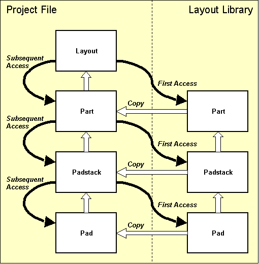
Figure 4-3: Layout Library Access
Changing the library path setting is meaningful only if a series of different part symbols are to be loaded from a library file which is not accessible through the predefined library path. Use the following commands to set the library path to the
demolib.ddb DDB file of the current directory:
| Settings |
| Select Library |
| Library Name ('c:/baelib/stdsym.ddb') ? | demolib |
With the commands above, the library path is set to the
demolib.ddb DDB file of the working directory, i.e., requested part symbols on subsequent load operations will be copied from
demolib.ddb.
The
,
and
functions from the
menu are used for placing parts. These functions work on the selected part set. Initially after loading a layout, all parts are selected, i.e., the system behaves as usual. The functions from the
submenu can be used to restrict and/or redefine the set of parts selected for placement. The
function issues a
message if all parts are already placed or a
message if all selected parts are already placed, but there are still unselected parts which have not yet been placed. The part set selection popup window displays placed selected parts as
[ name ], placed unselected parts as
( name ), unplaced selected parts as
: name and unplaced unselected parts as
< name >. See
chapter 4.4.1 for more information on part set definitions.
The
function is used to load and place parts on the current layout. On layout hierarchy level, the
function activates a net list part name popup menu with the part name prompt. This popup menu displays placed net list parts in brackets
([,
]). Unplaced net list parts are preceded by a colon
(:). When selecting or specifying an unplaced net list part name, this part is loaded for placement. Selecting an already placed net list part prompts for confirmation to replace the placed part. Entering an empty string to the part name prompt or selecting the
button loads the next unplaced net list part. This feature is also provided with the
function and works until all net list parts (from the part set) are placed. The system prompts for the library element name when specifying a part name which is not defined in the net list (e.g., when placing a constructive part). Popup menus are provided with the library element name query for selecting the library file and the library element name. The library file name list is derived from the layout library path defined with the BAE setup, i.e., all DDB files available in the directory of the layout library path are listed. The
button or
> input to the library file name prompt selects the standard layout library defined through the
function from the
menu. The
button in the library file name popup selects the current project file. A library element name query is activated after selecting the library file. Library elements can optionally be selected by typing both the library file name (i.e., one of the names displayed with the library file name popup), a slash
(/), and the library element name to the library element name prompt (typing
? for the element name activates a popup menu providing the list of library elements from the specified library file). An empty string input to the library element name query causes the system to use the library element previously selected with the
function (if there was already one specified).
The net list part name selection popups are also provided with the and functions from the menu. The library element name selection of the function is also implemented for placing pins (i.e., selecting padstacks) on layout part symbol level and for loading pads onto layout padstack level.
Use the following commands to load the part named
IC10 and place it at coordinate [1.2",1.8"]:
| Parts |
| Add Part |
| Part Name ? | ic10 |
| Move to [1.2",1.8"] |
The
function checks whether a part with the specified name exists in the net list. If the part is defined in the net list, then the system knows the package to be used for this part and automatically loads the corresponding part symbol (i.e.,
dil14 in the example above). The system issues an error message such as
Element not found!
if the requested part symbol is not available in the current job file or in the selected library. In this case you should use the function from the menu in to check whether the correct library is accessed.
Use the following commands to load and place two parts named
hole1 and
hole2 using the
hole3mm package type which was created in
chapter 4.2.3 in DDB file
demo.ddb:
| Parts |
| Add Part |
| Part Name ? | hole1 |
| Library Element Name ? | hole3mm |
| Move to [0.4",0.3"] |
| Add Part |
| Part Name ? | hole2 |
| Library Element Name ? | |
| Move to [0.4",2.5"] |
The (constructive) parts
hole1 and
hole2 are not defined in the net list, i.e., the system does not know the corresponding package types. The
function activates a library element name query with a popup menu providing access to all library files available through the predefined default library path. The
button of this menu can be used for accessing the job-specific library of the currently processed DDB file. After selecting the library file, another popup menu with a list of all symbols available in the selected library file is activated. An empty string input (i.e., just pressing the return key
![]() ) to the library element name query causes the system to use the part symbol loaded with the preceding
call.
) to the library element name query causes the system to use the part symbol loaded with the preceding
call.
Use the following commands to load and place the plug named
x1000:
| Parts |
| Add Part |
| Part Name ? | x1000 |
| Rotate Left |
| Move to [2.4",1.0"] |
Pressing the right mouse button during part placement activates a submenu which provides functions for specifying absolute placement coordinates, part rotation (even at arbitrary rotation angles) and part mirroring (for placing SMDs on solder side).
Use the following commands to place the next part:
| Parts |
| Add Part |
| Part Name ? | |
| Mirror On |
| Move to [1.8",1.4"] |
An empty string input (i.e., just pressing the return key
![]() ) to the part name query causes the
function to load the next unplaced net list part. In the example above, the system automatically loads the SMD capacitor named
) to the part name query causes the
function to load the next unplaced net list part. In the example above, the system automatically loads the SMD capacitor named
c100, which then is placed on solder side.
The facility for loading the next net list part (without knowing the corresponding part name) can also be activated with the
function. Use this command to place the part named
c101 as in
| Parts |
| Place Next Part |
| Mirror On |
| Move to [1.4",1.4"] |
Use the following commands to place the relay part named
k1, the resistor parts named
r100,
r101,
r102,
r103,
r104,
r105 and the switch named
s1000:
| Parts |
| Place Next Part |
| Move to [0.8",0.8"] |
| Place Next Part |
| Move to [1.0",2.4"] |
| Place Next Part |
| Move to [1.6",2.4"] |
| Place Next Part |
| Rotate Left |
| Move to [1.6",1.2"] |
| Place Next Part |
| Rotate Left |
| Move to [1.4",1.2"] |
| Place Next Part |
| Move to [2.1",2.1"] |
| Place Next Part |
| Move to [2.1",1.8"] |
| Place Next Part |
| Rotate Right |
| Move to [0.2",2.3"] |
The
function can be utilized for subsequently placing a series of parts at certain rotation angles and/or mirror modes (e.g., SMD parts). Use the following commands to set the standard placement rotation angle to 270 degrees and place the switches named
s1001 through
s1009:
| Parts |
| Set Default Angle |
| 270 Degrees Left |
| Place Next Part |
| Move to [0.2",2.1"] |
| Place Next Part |
| Move to [0.2",1.9"] |
| Place Next Part |
| Move to [0.2",1.7"] |
| Place Next Part |
| Move to [0.2",1.5"] |
| Place Next Part |
| Move to [0.2",1.3"] |
| Place Next Part |
| Move to [0.2",1.1"] |
| Place Next Part |
| Move to [0.2",0.9"] |
| Place Next Part |
| Move to [0.2",0.7"] |
| Place Next Part |
| Move to [0.2",0.5"] |
Use the following commands to complete the placement, i.e., place part
v1 (with absolute placement coordinates and 45 degree rotation angle) and part
v1000:
| Parts |
| Place Next Part |
| Set Angle |
| Angle (Deg./(R)ad) ? | -45 |
| Jump Absolute |
| Absolute X Coordinate (mm/") ? | 0.825" |
| Absolute Y Coordinate (mm/") ? | 1.225" |
| Place Next Part |
| Move to [1.2",1.6"] |
| Place Next Part |
The function issues the
All parts have been placed already!
message once all net list parts are placed. I.e., the function can also be used to check on placement completion.
After correctly executing all work steps of this chapter, the PCB layout example should look like the one shown in figure 4-4.
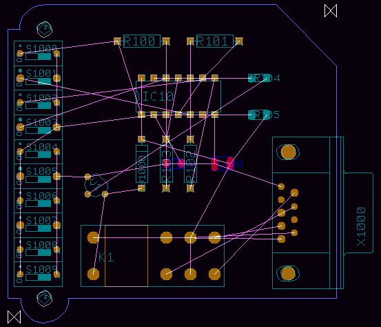
Figure 4-4: Layout with Part Placement
The function is used to move parts which are already placed on the layout. Pressing the right mouse button during part movement activates a submenu with special options for rotating and mirroring, absolute or relative placement coordinates input, etc. The function is used to delete placed parts from the layout. You should test these functions on the currently loaded layout and use the and functions for estimating design modifications and returning to the original design stage as shown in figure 4-4.
The
option is provided with the
Layout Editor submenus which can be called by pressing the right mouse button during interactive part placement. This option can be used to change the part package type of the currently placed part. The alternate package type can be selected from a list of layout part macros. The alternate part list is
either pre-defined in the logical library using the
loglib utility program (see
chapter 7.11)
or can be defined through an SCM symbol
$plname attribute value assignment such as
[package1,package2,...]. An error message such as
is issued if no alternate package types are defined for the currently processed part. An error message such as
is issued if the pin definitions on the selected alternate package type do not match the net list, i.e., if net list pins are missing on the selected macro. Alternate part package type assignments create a backannotation request which triggers automatic
when loading SCM plans to the
Schematic Editor (see
chapter 2.7).
requests also prevent the
Packager from forward annotation without confirmation (see
chapter 3.2.3).
Unrouted net list connections are displayed as airlines. During part placement, the function performs dynamic (real-time) recalculation of these airlines to display minimum length airline sets. I.e., the function is a most useful utility for achieving an optimum manual placement. Use the following commands to test different airline calculation methods supported through the function and note how the function type affects the way airlines are displayed:
| Settings |
| Mincon Function |
| Corners Horizontal |
| Mincon Function |
| Pins Vertical |
| Mincon Function |
| Mincon Off |
| Mincon Function |
| Corners H+V Sum |
The function from the menu is used to set the airline display mode to be applied during part movement. switches off the airlines display during part movement. does not recalculate the nearest connection points during part movement. dynamically recalculates the closest connection points (note how the airlines jump to the nearest pins or copper corners during part movement). is the default option.
The and options allow for a net-specific airline display, i.e., it is possible to fade-out () and/or fade-in () net-specific airlines by selecting the desired net(s) from a net name popup menu which optionally allows for multiple net selections through net name pattern specifications.
The option forces the graphical display of all airlines, whilst fades out all airlines.
The context menu which is available through the right mouse button during part placement provides the and options for selecting either part-specific or global airline display.
On layout hierarchy level, text (on documentary layers or on signal layers) and graphic (i.e., polygons such as documentary lines, documentary areas, passive copper areas, active copper areas, keepout areas, copper fill workareas) can be defined. For the following operations it is recommended to set the input grid to 1/20 inch (use the and functions from the menu) and to set the coordinate display mode to inch (use function from the menu).
Use the following commands to place the
DEMO text string adjacent to the right top of the board outline with a text size of 4mm on the
() documentary layer:
| Text, Drill |
| Add Text |
| Document Layer |
| Insertion Plan |
| Text ? | DEMO |
| Set Angle |
| Angle (Deg./(R)ad.) ? | -45 |
| Text Size |
| Text Size ( 2.54mm) ? | 4 |
| Move to [2.4",2.6"] |
Use the following commands to place the
Component Side text string with text size 2.54mm on the PCB component side signal layer (Top Layer, Layer n (Parts.)):
| Text, Drill |
| Add Text |
| Layer n (Parts.) |
| Text ? | Component Side |
| Text Size |
| Text Size ( 4.00mm) ? | 2.54 |
| Move to [1.00",2.55"] |
The
function which can be activated whilst placing texts sets the default text size for subsequent calls to the
function. Use the following commands to place a rotated and mirrored text with string
Solder Side on the PCB solder side (signal layer 1):
| Text, Drill |
| Add Text |
| Layer 1 |
| Text ? | Solder Side |
| Set Angle |
| Angle (Deg./(R)ad.) ? | 180 |
| Mirror On |
| Move to [1.80",2.55"] |
Texts placed on signal layers are subject to the design rule check. I.e., the DRC will issue distance errors for intersections between signal layer texts and other objects (pads, traces, copper areas, texts, etc.) placed on the same signal layer.
The
function from the
and/or
menu is used to move part names. Use the following commands to move the names of the SMD resistors named
r104 and
r105 on top of the parts:
| Text, Drill |
| Move Name |
| Move to "r104",[2.1",2.1"] |
| Move to [2.1",2.15"] |
| Move Name |
| Move to "r105",[2.1",1.8"] |
| Move to [2.1",1.85"] |
The
function from the
and/or
menu can be used for moving and/or placing selectable part attributes. Attribute text offsets defined through
override the global text offset set with
. The attribute to be moved is selected through a mouse-click on the attribute text. Since part names are internally stored as
$ attributes, the
function can also be used to move part names without changing the placement of other part attributes.
Part names and part attribute texts of group-selected parts can be reset to their library-defined default positions using the function implemented with the gedgroup User Language program.
The
Layout Editor automatically activates a measuring function when placing new text with string
#. This function determines the distance between the two input coordinates subsequently to be specified. The resulting text string emerges from the corresponding distance value; the length units (inch or mm) result from the current coordinate display mode selected with the
menu function. Use the following commands to apply measuring on the bottom right board outline edge and place the resulting distance value (2.2") on the
() documentary layer:
| Text, Drill |
| Add Text |
| Document Layer |
| Insertion Plan |
| Text ? | # |
| Move to Left Coordinate,[0.6",0.3"] |
| Move to Right Coordinate,[2.8",0.3"] |
| Move to [1.50",0.15"] |
Use the following commands to create a documentary line and two arrow-shaped documentary areas on the () documentary layer to indicate the previously defined measuring:
| Areas |
| Add Document Line |
| Insertion Plan |
| Move to [0.6",0.15"] |
| Move to [0.8",0.15"] |
| Done |
| Add Document Area |
| Insertion Plan |
| Move to [0.6",0.15"] |
| Move to [0.65",0.2"] |
| Move to [0.65",0.1"] |
| Done |
| Add Document Area |
| Insertion Plan |
| Move to [2.8",0.15"] |
| Move to [2.75",0.2"] |
| Move to [2.75",0.1"] |
| Done |
Use the following commands to create a circle-shaped passive copper area on signal layer 2:
| Areas |
| Add Passive Copper |
| Layer 2 |
| Move to [0.95",1.6"] |
| Arc Left |
| Move to [0.8",1.6"] |
| Done |
Use the following commands to create an active copper area on signal layer 1 and assign this copper area to net
Vdd:
| Areas |
| Add Active Copper |
| Net Name ? | vdd |
| Layer 1 |
| Move to [2.4",1.7"] |
| Move to [2.7",1.7"] |
| Move to [2.7",2.2"] |
| Move to [2.6",2.3"] |
| Move to [2.4",2.3"] |
| Done |
Use the following commands to define a keepout area on signal layer 1 and a keepout area on signal layer (keepout areas define layer-specific regions on the PCB where no traces, no copper areas, no texts, etc. are allowed to be placed):
| Areas |
| Add Keep Out Area |
| Layer 1 |
| Move to [1.8",1.2"] |
| Move to [2.2",1.2"] |
| Move to [2.2",0.9"] |
| Move to [1.7",0.9"] |
| Done |
| Add Keep Out Area |
| All Layers |
| Move to [0.6",2.6"] |
| Move to [0.6",2.1"] |
| Move to [0.9",2.1"] |
| Move to [0.9",2.6"] |
| Done |
The menu provides functions for interactive routing on layout and/or part hierarchy level, i.e., for manually creating new traces and for modifying or deleting existing traces and/or trace segments. Arbitrary track widths can be defined for individual trace segments or complete routing paths. Special or critical nets such as the power supply can be pre-routed and then fixed to prevent the Autorouter from rerouting such nets.
During manual routing, the system provides a highlight on all objects of the currently routed signal. After completing the routing of a certain connection, the corresponding airline is removed from the display. Short-circuits and distance violations introduced by manual routing are immediately indicated by the Online DRC using highlight and/or distance error boxes.
If you fail to connect certain (off-grid) pins with the current input grid settings, then you should use the functions for selecting a smaller input grid (or even release the grid lock).
The middle mouse button can be used to activate the menu at any time during manual routing. I.e., important display options such as zoom scale, grids, colors, etc. can be changed without cancelling the currently active trace edit function.
The menu also provides the function for selecting the pick preference layer. The pick preference layer is used to resolve ambiguities at the selection of trace elements placed at the same position but on different layers. The pick preference layer is also the default routing layer when starting to route from a drilled ("All Layer") pad or from a copper-free position. On default, the pick preference layer is set to signal layer 1 (solder side).
The algorithm for picking trace corners and trace segments picks the trace element with minimum distance from the pick point if more than one possible pick element is within snapping distance. This allows for reliable selection of trace elements even when working in (small) zoom overview display modes. The trace pick snapping distance is automatically adjusted to the trace width. I.e., trace elements (of wide traces or in high zoom display modes) can easily be picked without having to hit the trace center line.
The function from the Layout Editor menu is used to mark all connections of the selected net with a special ("Highlight") color. Any power layer heat-trap circles and isolations of the selected net is included with the highlight display, and isolated pins and active copper areas can also be selected for highlight. Starting a new trace on a passive copper area triggers a highlight for the nets connected to that copper area. The function works as a toggle. To reset the highlight of a certain net, pin or active copper area, simply re-select that object with the function. Advanced color support and highlight reset facilities are provided through the (default mode), (with highlight color selection) and (for clearing all nethighlight) options of the function.
In BAE HighEnd, the function causes a highlight and/or de-highlight of the selected nets in all currently loaded plans of the current project file on layout board and schematic sheet level (global net highlight, cross-probing).
The
Bartels AutoEngineer layout system utilizes special padstack symbols (vias) for connecting different layers of the PCB. At least one via assignment is required before any routing function (i.e. either a trace function or the
Autorouter) can be activated. Use the following commands to insert the
estk padstack symbol to the currently active via list:
| Parts |
| Select Via |
| New/Delete: Via Name ? | estk |
| New/Delete: Via Name ? | |
The
estk padstack symbol is used as pin symbol on the already placed part
v1000 (package type
d04a25). I.e.,
estk is available in the current job file. A series of via padstack definitions are provided with the layout libraries shipped with the BAE software. Usually the padstack symbol named
via can be used as standard via. The via assignments introduced with
are stored with the layout element. The
function issues the following error message if no via is selected:
Default via not defined!
The system is capable of processing several different via definitions at a time in order to support blind and buried vias. The via assignment list can be changed at any time. Previously placed vias will not be affected by via list modifications, i.e., the currently defined via list will apply for the interactive routing of new traces. When changing layers during manual routing the Layout Editor will automatically place vias with the least possible layer usage (if padstacks are defined and selected to the via list accordingly). The current via assignment list will also be used by the Autorouter, and, with the use of blind and buried vias, the Autorouter will minimize layer occupancy as well (this is true for all traces except for fixed traces which will not be processed by the Autorouter).
The trace function submenus provide options for toggling between thin and wide default track widths during manual routing (necking). The standard values for these default track widths can be changed with the function from the menu, where the options (default value 0.3mm) and (default value 1.0mm) are provided. The routing of a new trace always starts with the thin default track width.
Use the following commands to route from pin
A1 of part
K1 to pin
C1 of the same part (both pins are connected to net
Vdd):
| Traces |
| Add Trace |
| Move to "K1.A1",[0.8",0.8"] |
| Move to Corner Point,[0.8",0.95"] |
| Move to Corner Point,[1.6",0.95"] |
| Move to "K1.C1",[1.6",0.8"] |
| Done |
Each trace corner point is set by pressing the left mouse button. The routing of a trace path is completed with the option from the submenu available with the right mouse button. This submenu is also available during trace editing with functions such as or where the routing layer or the track width can be changed, arc-shaped trace segments can be created, relative and absolute coordinate input can be specified, etc.
Use the following commands to connect the pins
C2 and
C1 of part
K1 with a trace segment on signal layer 2:
| Traces |
| Add Trace |
| Move to "K1.C2",[1.6",0.5"] |
| Layer 2 |
| Move to "K1.C1",[1.6",0.8"] |
| Done |
Use the following commands to create a trace segment on signal layer 1 starting at pin
9 of the plug named
X1000 and ending with a via to connect to the previously generated trace:
| Traces |
| Add Trace |
| Move to "X1000.9",[2.45",0.85"] |
| Move to Corner Point,[2.45",0.65"] |
| Move to Vertical Trace Segment,[1.6",0.65"] |
| Layer 2 |
| Done |
Use the following commands to deselect
estk from the via list, select the padstack symbol
via (which has been created in
chapter 4.2.2 in the
demo.ddb DDB file) to the via list, and then route a trace on signal layer 2 starting at pin
K of the diode named
V1000 and ending with a via connecting to the horizontal trace between the pins
A1 and
C1 of part
K1:
| Parts |
| Select Via |
| New/Delete: Via Name ? | estk |
| Please confirm (Y/N) ? | y |
| New/Delete: Via Name ? | via |
| New/Delete: Via Name ? | |
| Set Edit Layer |
| Layer 2 |
| Traces |
| Add Trace |
| Move to "V1000.K",[1.2",1.6"] |
| Move to Corner Point,[1.1",1.6"] |
| Move to Horizontal Trace Segment,[1.1",0.95"] |
| Layer 1 |
| Done |
You should now gain more practice by using the trace functions on the currently loaded layout in order to create and/or modify more traces (move, cut and delete trace segments; insert, move and delete trace corner points; change track widths, create arc-shaped traces, etc.). Note the , and options provided with the submenu of the function. The default mode just moves the corner points of the processed trace segment, whilst the mode also rearranges adjacent trace segments in order to keep the angles between the processed trace and the adjacent segments constant. considers intersection points between new and neighbouring segments and rearranges neighbouring segments accordingly. This feature is especially useful for moving diagonal segments at trace corners. The option is applied if neighbouring segments cannot be rearranged. Use the and functions to estimate design modifications and return to the original design stage.
It is recommended to fix pre-routed traces which must not be modified and/or rerouted by the
Autorouter. Use the following commands to fix all prerouted traces of net
Vdd:
| Traces |
| Fix Trace/Net |
| Net |
| Move to Signal/Net "Vdd",e.g.[2.0",0.65"] |
The function is used to release fixed traces or nets. During fix and release operations the Layout Editor provides a specific highlight for indicating currently fixed elements.
The Layout Editor trace functions for interactive routing keeps traces and vias fixed when processing pre-routed fixed traces. I.e., when manipulating pre-routed fixed traces, there is no need of re-fixing such traces to prevent the Autorouter from re-routing and/or rejecting pre-routed traces.
The BAE layout system is equipped with powerful Autoplacement functions. The part set functions are used for selecting and/or deselecting parts for subsequent placement operations. The matrix placement facilities are used for placing selectable part sets onto definable placement grids. Initial placement functions are provided for performing fully automated part placement. The system also provides placement optimization functions for automatic part and pin/gate swap.
The Autoplacement functions are available from the , and submenus of the Layout Editor menu.
Start the
Layout Editor if it is not yet active and load the layout
board from the
demo.ddb DDB file.
Use the
function from the
menu to delete the resistors named
r100 and
r101, and apply group functions to delete the switches named
s1000 through
s1009:
| Parts |
| Delete Part |
| Move to "r100",[1.0",2.4"] |
| Delete Part |
| Move to "r101",[1.6",2.4"] |
| Groups |
| Group Polygon |
| Parts |
| Select |
| Move to [0.1",0.4"] |
| Move to [0.6",0.4"] |
| Move to [0.6",2.4"] |
| Move to [0.1",2.4"] |
| Done |
| Delete Group |
Autoplacement features and functions are used throughout the following sections to place the deleted parts back onto the layout.
The
submenu provides features for selecting the parts to be subsequently placed. Parts can be selected and/or deselected according to set principles either by specifying part names
(c1,
r2,
ic15, etc.) or by specifying package types
(dil14,
so20,
plcc44, etc.), where wildcards are also permitted. The user can also select parts from certain blocks of a hierarchical circuit design. With the Part Set functions the user is able to control the placement process in a way that e.g., first the plug(s) can be placed, then the DIL packages, then the capacitors, etc.
Use the following commands to deselect all unplaced parts:
| Parts |
| Part Set |
| All |
| Deselect |
| Deselect all parts ? | j |
| Abort |
Now you might want to use the command to have a look at the part list:
| Parts |
| Part Set |
| List Parts |
The function provides verbose output of all net list parts:
File : demo.ddb Layout : board Parts : 23
: c100 chip1210 P : c101 chip1206 P : ic10 dil14 P : k1 relais P : r100 r04a25 U : r101 r04a25 U : r102 r04a25 P : r103 r04a25 P : r104 minimelf P : r105 chip1206 P : s1000 s1dilo U : s1001 s1dilo U : s1002 s1dilo U : s1003 s1dilo U : s1004 s1dilo U : s1005 s1dilo U : s1006 s1dilo U : s1007 s1dilo U : s1008 s1dilo U : s1009 s1dilo U : v1 to92 P : v1000 d04a25 P : x1000 xsubd9bl P - End -
Each part is listed with part name, library name and placement status, respectively. The placement status is indicated using either of the characters
U,
P or
S.
U indicates that the part is neither placed nor selected for placement.
P indicates that the part is already placed on the layout.
S indicates that the part is not yet placed but selected for subsequent placement operations. Press
X and the return key
![]() to exit from the parts list.
to exit from the parts list.
Use the following commands to select all unplaced parts with part names starting with an
r:
| Parts |
| Part Set |
| Part(s) |
| Select |
| Part Name ? | r* |
| Part Name ? | |
The and part set selection options from the function also provide a popup menu for part selections. With the option, the popup menu only displays unselected parts, whilst with the option, only selected parts are displayed. A part name pattern can be entered for part set selections.
The above commands selected the two resistors
r100 and
r101 for subsequent placement operations. You can check this with the
function (see placement status
S for these two parts).
The
function can be used to select all unplaced parts for placement. The
function can be used to select parts with library names (such as
so16 for all unplaced 16 pin small outline package types or
dil* for all unplaced dual-in-line package types). The
option can be used to deselect parts from the set of parts to be subsequently placed.
The
and
functions from the
menu can be used for selecting and/or deselecting parts which are defined in certain blocks of a hierarchical circuit design. I.e., parts are selected or deselected through block names. Part block names are automatically transferred and stored by the
Packager utilizing the internal
$blkname part attribute.
It has already been mentioned that the
and
functions work on the part set (see section Placing Parts in
chapter 4.3.2). Use the following commands to set the coordinate display mode to inch, and place all parts of the currently defined part set (i.e., the two resistors named
r100 and
r101):
| Settings |
| Coordinate Display |
| Display Inch |
| Parts |
| Place Next Part |
| Move to [1.0",2.4"] |
| Part |
| Place Next Part |
| Move to [1.6",2.4"] |
| Parts |
| Place Next Part |
The function issues the
All selected parts have been placed already!
message if no more part is selected for subsequent placement operations anymore (i.e., all parts of the previously defined part set are already placed).
Matrix placement is a special initial placement process for automatically placing selected parts on certain matrix-defined insertion positions.
Use the following commands to select all parts with library name
s1dilo (i.e., the switches named
s1000 through
s1009) for subsequent placement operations:
| Parts |
| Part Set |
| Select Macro |
| Select |
| Library Element Name ? | s1dilo |
| Library Element Name ? | |
Set the default placement rotation angle to 270 degree (without mirroring (the option is probably located in the group of the dialog from the menu when working with customized BAE user interfaces):
| Parts |
| Default Angle |
| 270 Degrees Left |
Use the following commands to define a placement matrix, place all selected parts onto this matrix and delete the placement matrix definition again:
| Parts |
| Matrix Placement |
| Define Matrix |
| Move to Matrix Origin,[0.2",2.3"] |
| Move to Matrix Element Size Designation,[0.3",2.1"] |
| Move to Matrix Size Designation,[0.2",0.5"] |
| Place Matrix |
| Delete Matrix |
The function automatically places all parts of the currently defined part set onto the placement matrix, also considering the current default placement rotation angle and mirror mode settings.
Now all net list parts are placed. You might want to check this with the function.
The system provides full automatic initial placement algorithms. The initial placement functions automatically place all unplaced net list parts inside the board outline onto the currently selected input (placement) grid, considering pre-placed parts (connectors, LEDs, etc.), keepout areas and net list preferences, and also featuring automatic block capacitor and SMD device recognition. Automatic SMD part mirroring can optionally be enabled to allow SMD placement on the solder side. Either unrestricted or restricted automatic part rotation in 90 degree steps can be applied; restricted part rotation can be used to simplify subsequent insertion processes. A generally applicable part expansion value can optionally be defined to ensure minimum clearance between adjacent parts. The placement algorithms are guarded by adjustable strategy parameters for net list preference control and for the consideration of part segment matching/fitting. Rip-up and retry passes are automatically applied during the placement process to optimize board area yield.
The initial placement routines are integrated to the submenu which provides the following functions:
| Parts |
| Auto Placement |
| Full Autoplacer |
| Cluster Placer |
| Area Placer |
| Single Pass Optimizer |
| Multi Pass Optimizer |
| Part Pin Factor |
| Segment Fit |
| Mirroring Mode |
| Rotation Mode |
| Part Expansion |
| Number of Retries |
| Number of Passes |
| P/G Swap Method |
The , and function can be used to perform automatic part placement. Only the parts from the current part set (see chapter 4.4.1) are placed. Placed parts which are not selected to the current part set are treated like fixed parts. This feature allows for automatic placement of selectable part groups.
The first part selected for placement will be positioned at the placement start point. The function automatically designates the placement start point. The and functions prompt the user for the placement start point (prompt ). The placement of the first part determines the placement of subsequent parts. I.e., the selected placement start point position has crucial meaning for the complete placement process (with regard to 100% completion success and/or the quality of the achieved placement). If the first part cannot be placed at the placement start point, then no subsequent part can be placed either. If the placement start point is selected outside the board outline, then no part can be placed at all. If no board outline is defined then there are no restrictions on selecting the placement start point, however parts could then be placed even outside the boundaries of the currently loaded layout element.
After starting an initial placement function the placement progress is indicated in the status line by a progress message such as . The autoplacement process can be stopped by keystroke. Each autoplacement stop request is verified with user confirmation and will be denoted by a message such as . Note that there might be a short delay on stop requests since any currently active autoplacer rip-up and retry pass must be completed.
A message such as
is issued after completing an initial placement function to indicate that all parts have been successfully placed. If the autoplacer fails to complete 100% part placement using the current parameter settings, then a message such as
is issued, denoting the number
<n> of yet unplaced parts. On incomplete initial placement it is recommended to change placement parameters (use smaller placement grid, reduce part expansion, use unrestricted part rotation, allow SMD mirroring; see below on how to set placement parameters) and restart the autoplacer (after
and/or selecting a different placement start point) to achieve 100% part placement.
The function performs cluster placement (see below) with automatic placement start point selection and subsequently applies multi-pass placement optimization (see chapter 4.4.4 below) using the currently selected placement optimization parameters (number of passes and the pin/gate swap method). The placement start point results from the board outline gravity point. No part can be placed using the function, if the board outline gravity point is outside the board outline (e.g., on L-shaped PCBs) then ; in this case either or must be used instead of .
If no board outline is defined, then the placement start point results from the absolute origin of the currently loaded layout element. In this case it is recommended to zoom to overview after completing the placement process since parts can be placed beyond the currently defined and/or visible layout element boundaries.
After activating the function the user is expected to select the placement start point interactively. The first part selected for placement is positioned at the placement start point.
The
function analyzes the net list to classify the nets and parts contained in the net list. Parts are grouped to clusters, and these clusters are subsequently placed on the layout with respect to pre-calculated cluster-dependent placement priorities. Each cluster is grouped by selecting a multi-pin part and a series of connected parts with less than four pins. Parts which are connected to power signals only (such as block capacitors) are postponed during cluster generation and will be assigned to clusters with corresponding power connections afterwards. This method of cluster building automatically involves block capacitor recognition, thus featuring appropriate block capacitor placement nearby corresponding ICs. Parts and/or part clusters are assigned and/or processed due to alphabetical part name order. It is recommended to introduce part type grouping by choosing appropriate type-specific part name patterns, i.e., to insert connectors at the end of the part name list to avoid block capacitor assignment to connectors and/or plugs (e.g., by using name pattern
x??? for connectors and/or plugs,
ic??? for integrated circuits, etc.).
The function performs area placement with interactively selectable placement start point. Area placement does not consider any net list preferences, i.e., only part dimensions are considered as placement criteria. The function can be used to estimate part placement area requirements, i.e., to check whether the board area is large enough to place all parts.
The part pin factor is used to control the sequence of parts and/or clusters to be placed. The next part to be placed is selected by applying a combination of two strategies. The first strategy simply selects the part with the maximum number of pins connected to already placed parts. The second strategy selects the part with the maximum ratio of number of part pins connected to already placed parts to total part pin count. The part pin factor value designates which strategy has higher priority. Use the
| Parts |
| Auto Placement |
| Settings |
| Part Pin Factor |
| Pin Count Weight [0.0,1.0] (0.90) ? |
function to set the desired part pin factor value in the range 0.0 (for considering connection counts only) to 1.0 (for considering connection count to total pin count ratios only). On default the part pin factor value is set to 0.9. A high part pin factor value usually results in a better distribution of nets, but could cause excessive placement area fragmentation on high-density layouts by early placement of small parts, which might prevent from placing larger parts afterwards.
The segment fit value is used to control on how much part edge length matching should be considered by the placement algorithm, i.e., whether preference should be given on placing parts with equal edge lengths side by side. Use the
| Parts |
| Auto Placement |
| Settings |
| Segment Fit |
| Segment Fit [0.0,1.0] (0.10) ? |
function to set the weight factor for considering part edge length matching. Valid segment fit values are in the range 0.0 (no segment fit preference) to 1.0 (high segment fit preference). On default the segment fit value is set to 0.1. High segment fit values usually result in better looking layouts, and can increase the routability of layouts with many bus connections. Better routability of high-density layouts with a "random" connection distribution however can be achieved using smaller segment fit values.
The part mirroring mode has effect on the placement of SMD parts only. With the default option, SMD parts can only be placed on the PCB part side. is used to allow unrestricted placement of SMD parts on both the part side and the solder side. The option restricts automatic part mirroring to 2-pin SMDs only, thus allowing for solder side placement of small parts such as block capacitors whilst placement of SMDs with more than 2 pins is forced onto the PCB part side. Use the
| Parts |
| Auto Placement |
| Settings |
| Mirroring Mode |
| No SMD Mirroring |
| SMD Mirroring |
| SMD 2 Pin Mirroring |
function to select the desired SMD mirroring option.
The part rotation mode is used to apply either unrestricted or restricted automatic part rotation in 90 degree steps. With the default option all parts can be placed at arbitrary 90 degree rotation steps. Option can be used to restrict part rotation, i.e., to allow no rotation or 90 degree left rotation only. Restricted part rotation can be used to simplify subsequent insertion processes which will also result in a reduction of CPU time required by the placement algorithms. Use the
| Parts |
| Auto Placement |
| Settings |
| Rotation Mode |
| 0- 90 Deg. Rot. |
| 0-270 Deg. Rot. |
function to select the desired part rotation mode.
The parts are placed onto the currently selected input grid (to be set using the function from the menu). The placement area required for each part (i.e., the part size) emerges from the element boundaries of the corresponding part macro. This should be taken into consideration at the definition of element boundaries when creating part macro symbols. It is recommended to refrain from defining unnecessarily large part macro element boundaries to avoid redundant placement area occupancy.
A generally applicable part expansion value can optionally be defined in order to ensure minimum clearance between adjacent parts (on low-density layouts). Use the
| Parts |
| Auto Placement |
| Settings |
| Part Expansion |
| Expansion Value ( 0.00mm) ? |
function to set the desired part expansion value. On default the part expansion value is set to 0.0mm (i.e., no part expansion is applied). Note that the specified part expansion value with no regard to different part macro type dimensions is equally applied on each part macro type except for block capacitors. Block capacitors are automatically recognized and will be placed as close as possible to the ICs to be supplied. The preferably places block capacitors either on top or on the right-hand side of the integrated circuits, according to the ICs orientation.
The features a function for automatically reducing part expansion settings by 25 percent steps until either complete placement is achieved or part expansion is reduced to zero.
The initial placement algorithms are designed to consider only connections to/between already placed parts. Intermediate placement results might show up with alternate positions to be more optimum for a series of previously autoplaced parts. For this reason, rip-up and retry passes are activated for replacing already placed parts in order to find a more optimum placement. Note that preplaced unfixed parts are also processed by the rip-up and retry passes. It is strongly recommended to fix those preplaced parts which must not be replaced. Parts can be fixed using Layout Editor group functions. Use the
| Parts |
| Auto Placement |
| Settings |
| Number of Retries |
| Number of Retries [0,9] ( 2) ? |
function to specify the number of retry passes to be applied during the autoplacement process. Two retry passes are used on default; i.e., one rip-up and retry pass is applied after placing half of the unplaced parts and one rip-up and retry pass is applied at the end of the autoplacement process. It is recommended to refrain from specifying too many retry passes since this not only increases CPU time requirements but also can result in a deterioration of intermediate placement results since small parts such as block capacitors might not be correctly replaced with their clusters.
The placement optimization features of the BAE layout system include functions for automatic part and pin/gate swap. The part swap facility mutually exchanges identical components at their insertion position in order to minimize unroutes lengths. The pin/gate swap facility analogously performs an iterative exchange of gates and/or pins and pin groups, where gates or groups can also be swapped between different parts. The admissibility of pin/gate swaps is fairly controlled with appropriate library definitions. Either single pass or multi pass optimization can be applied. Different swap methods can be selected through the function, with the default option to perform both component and pin/gate swap, to switch off pin/gate swap and to switch off component swap. Applying placement optimization usually causes a significant simplification of the routing problem, thus considerably reducing runtime at the subsequent Autorouting process.
Use the following commands to perform a triple-pass placement optimization with both component and pin/gate swaps:
| Parts |
| Auto Placement |
| Settings |
| Number of Passes |
| Number of Passes : 2 (1..99) ? | 3 |
| Multi Pass Optimizer |
During optimization a status line message instantly reports the number of parts processed by the current optimizer pass. Placement optimization can be interrupted at any time by pressing an arbitrary key on the keyboard.
Wait until all optimizer passes are completed and use the function to estimate how placement optimization did change the complexity of the "ratsnest" (unroutes).
Fixed parts are excluded from placement optimization. It is strongly recommended to fix critical parts before running the placement optimization. Critical parts are those which must not be replaced (e.g., plugs, switches, LEDs, etc.) or where pin/gate swaps are not allowed (e.g., relays, multi-opamps, etc.). Parts can be fixed using
Layout Editor group functions. Please note that automatic pin/gate swap should only be performed if all of the swap definitions stored with the logical library are permitted. Select the
option from the
function to switch off automatic pin/gate swap if you are in doubt about the correctness of swap definitions. Consider please that usually no pin/gate swap is allowed for plugs. Swaps for parts with special attribute values (e.g., resistor networks with attribute
$val must be defined internal to prevent the system from swapping gates between parts with different values. See
chapter 7.11 of this manual for a description of the
loglib utility program and how to introduce pin/gate swap definitions to the logical library.
With real jobs you should make sure that all of the required power layers are defined (use the function from the Layout Editor menu), the top signal layer setting is correct (use the function from the Layout Editor menu) and pre-routed critical traces such as power supply are fixed, before starting the autorouting process. After finishing the autorouting, you should always run a from the Layout Editor before generating manufacturing data with the CAM Processor.
The user interface of the Bartels Autorouter is similar to the one of the Layout Editor. The Bartels Autorouter provides standard autorouting functions (full and initial routing, rip-up and retry routing, optimizer) and a series of enhanced placement and routing features such as automatic pre-placement with placement optimization, single net routing, net-group routing, component routing, area and/or block routing, mixed-grid routing, selective component and pin/gate swap during rip-up routing, etc. The Autorouter version provided with the BAE HighEnd system provides powerful autorouting technologies based on patented neural network technology. The BAE HighEnd Autorouter supports skilled analogue signal routing, automatic microwave structure generation, grid-less object-orientated routing with automatic placement optimization, etc. The BAE HighEnd Autorouter also provides features for routing problem recognition and/or classification and for learning and automatically applying problem-adapted routing strategies and/or rules.
The function from the Layout Editor menu is used to start the Autorouter. After activating this function, the system automatically saves the currently loaded layout and the Autorouter program module starts. The Autorouter automatically re-loads any previously loaded layout. The layout requires a board outline definition (to be defined with the function from the Layout Editor menu) and a valid via assignment list (use function from the Layout Editor menu). Before starting any autorouter procedure, all net list parts must be placed with correct package types inside the board outline (no part or pin neither any pre-routed trace or via can be placed outside the board outline).
The following error messages might be issued when activating an Autorouter procedure:
| Cause: | PCB board outline definition is missing |
| Fix: | Layout Editor - - - ... |
| Cause: | no via assignment |
| Fix: | Layout Editor - - - ... |
| Cause: | not all net list parts are placed on the layout or there are net list parts placed with wrong package types |
| Fix: | use Layout Editor - - to remove net list parts with wrong package types; then use manual or interactive placement functions to complete the part placement |
| Cause: | net list part(s) and/or net list part pin(s) placed outside board outline |
| Fix: | correct part placement |
| Cause: | pre-placed, fixed via(s) placed outside board outline |
| Fix: | unfix and/or delete via(s) outside board outline |
| Cause: | pre-routed, fixed trace(s) placed outside board outline |
| Fix: | unfix and/or delete trace(s) outside board outline |
| Cause: | via list contains invalid via definition(s) |
| Fix: | correct via definition(s); there must be at least one via for connecting all signal layers, and each via must contain a drill hole and pads for at least two adjacent signal layers |
| Cause: | layout contains ambiguous library part definition(s) such as part(s) with more than one padstack placed at the same pin position |
| Fix: | correct library part definition(s) |
| Cause: | layout contains ambiguous library pad and/or padstack definition(s) such as pad(s) with more than one copper/connection area or padstack(s) with more than one pad placed on same layer |
| Fix: | correct library pad and/or padstack definition(s) |
Other error messages might be issued if the layout contains short circuits caused by pre-routed fixed traces.
The Autorouter standard/sidmenu user interface provides a menu area on the right side, consisting of the main menu on top and the currently active menu below that main menu. After entering the Autorouter the menu cursor points to the function.
The Windows and Motif versions of the
Autorouter can optionally be operated with a pull-down menu user interface providing a horizontally arranged main menu bar on top. The
WINMENUMODE command of the
bsetup utility program is used to switch between
SIDEMENU and
PULLDOWN Windows/Motif menu configurations (see
chapter 7.2 for more details).
The following main menu is always available whilst processing layouts with the Autorouter:
| Undo, Redo |
| Display |
| Preplacement |
| Autorouter |
| Interaction |
| Options |
| Control |
| Strategy |
| Parameter |
| Utilities |
The functions provided with the menu allow to use the Autorouter without fear of causing damage. Up to twenty commands can be reversed or undone using and then reprocessed with . This is true even for complex processing such as complete autorouting passes or User Language program execution. ensures data security and provides a powerful feature for estimating design alternatives.
The or menu can either be activated by selecting the corresponding main menu item or by pressing the middle mouse button. Activation through the middle mouse button is even possible whilst performing a graphical manipulation such as selecting a net or component for routing. The or menu provides useful functions for changing display options such as zoom window, zoom scale, input and/or display grids, grid and/or angle lock, color settings, etc.
The menu of the Autorouter is equal to the menu of the Layout Editor (see chapters 4.4.3 and 4.4.4). The Autorouter provides the same initial placement and placement optimization functions as already known from the Layout Editor, allowing for initial placement and placement optimization to be applied in the Autorouter without having to go back to the Layout Editor.
The menu provides the functions for activating autorouting procedures such as , , , and . The function is used to run a series of router passes previously defined with the function.
The menu provides the functions for activating special routing operations such as single net routing, net group routing, component routing, area/block routing, etc.
The menu is used to set fundamental Autorouter options for subsequent router passes. These parameters define the design rules and technology requirements to be considered by the Autorouter (signal layer count, layer assignment, routing grid with half-grid routing option, standard trace width, standard minimum distance, maximum via count, via grid, on-grid or off-grid trace bending, pin contact mode). The parameters defined from the menu are stored with the layout. Changes to basic routing option parameters (signal layer count, routing grid, toggle half-grid option, standard trace width, standard minimum distance, pin contact mode) cause an automatic router restart (with discard of current routing results) when re-entering some standard autorouting process such as , initial routing, SMD fan out routing, rip-up routing, optimizing and .
The menu provides basic functions for controlling the routing process such as setting the optimizer passes count, activate/deactivate multi-net pattern recognition during rip-up and/or optimization, set the persistence of the rip-up router, activate automatic SMD fan out routing and turn on or turn off automatic security copy.
The menu provides functions for setting the strategy parameters and heuristic cost factors to be used by subsequent router and optimizer passes (optimizer routing direction, via costs, pin channel costs, counter direction costs, direction change costs, packing costs, dynamic density cost factor, bus bending costs, rip-up distance costs, trace crossing costs, diagonal routing costs, off-grid routing costs).
The menu provides functions for selecting the layout library, setting the coordinate display mode, selecting the function for the airline display and activating the automatic design data backup feature.
The menu provides functions for exiting BAE, returning to the BAE main shell, calling the Layout Editor and starting User Language programs. This menu also provides important file management functions such as load and save layout elements or list DDB file contents.
The BAE software comes with User Language programs for activating a modified Autorouter user interface with many additional functions (startups, toolbars, menu assignments, key bindings, etc.). The bae_st User Language program is automatically started when entering the Autorouter bae_st calls the uifsetup User Language program which activates predefined Autorouter menu assignments and key bindings. Menu assignments and key bindings can be changed by modifying and re-compiling the uifsetup source code. The hlpkeys User Language program is used to list the current key bindings. With the predefined menu assignments of uifsetup activated, hlpkeys can be called from the function of the menu. Menu assignments and key bindings can be listed with the uifdump User Language program. The uifreset User Language program can be used to reset all currently defined menu assignments and key bindings. uifsetup, uifdump and uifreset can also be called from the menu of the keyprog User Language program which provides additional facilities for online key programming and User Language program help info management.
The Windows and Motif pull down menu user interfaces of the Autorouter provide facilities for cascading submenu definitions. I.e., submenus can be attached to other menu items. The uifsetup User Language program configures cascading submenus for the pulldown menu interfaces of the Windows/Motif Autorouter modules. This allows for easy submenu function location (and activation) without having to activate (and probably cancel) submenus. The function repeat facility provided through the right mouse button supports cascading menus to simplify repeated submenu function calls.
The following Windows/Motif parameter setup dialogs are implemented for the Autorouter:
The uifsetup User Language program replaces the parameter setup functions of the Windows and Motif pulldown menus with the above menu functions for activating the corresponding parameter setup dialogs.
When using pulldown menus under Windows and Motif, the uifsetup User Language program configures the following modified Autorouter main menu with a series of additional functions and features:
| File |
| Edit |
| View |
| Preplacement |
| Autorouter |
| Settings |
| Utilities |
| Help |
The Autorouter provides an in-built feature for automatically saving important design and operational parameters with the currently processed SCM sheet and/or SCM library hierarchy level. The following parameters are stored to the current design file when activating the function:
Parameter sets are stored using the current layout element name. When loading a layout, the corresponding parameter set is automatically loaded and/or activated, thus providing a convenient way of activating a default parameter set suitable for processing the selected design.
The current routing result is displayed graphically and through statistical readouts whilst routing is in progress. Graphic output and statistical readout during routing can be deactivated by pressing key d. The message is displayed whilst router graphic output is deactivated. Pressing the 'd' key again reactivates the graphic output and the statistical readout. The routing process accelerates by up to 10 percent if graphic output is deactivated. A screen redraw is automatically performed after the routing process has finished.
The number of currently routed connections (compared to the total connection count) and the global via count are continuously reported in the status line whilst during Autorouting processes. Additionally, a routing pass info window for displaying internal routing procedure information is provided on the right side of the
Autorouter user interface. This info window contains a status line for identifying the currently active router pass type
(L - Load Layout,
S - SMD Via Preplacement Pass,
I - Initial Routing Pass,
R - Rip-Up Pass,
P - Optimizer Pattern Search Pass,
O - Optimizer Pass) and the number
n of processed elements in relation to the total number
m of elements to be processed by the current router pass (display
n/m). The status line ends with the current pass number
c and the total number
p of passes to be processed (display
c/p). The values displayed with the router pass status line cannot be used for accurate total routing time predictions since the required time for completing the routing of each net and/or connection strongly depends on the current routing complexity.
The menu is used to set parameters for controlling graphical output. The zoom functions (, , ) are used to select the workspace to be displayed. Usually, one would use to display the complete Autorouter work area (i.e. the workspace designated by the board outline). is the default setting after starting the Autorouter. The functions for changing the zoom factor ( and ) and the function can only be executed if layout data is already loaded.
The
function is used to change the current color setup. The
function is used to load a predefined color table. On default, the
Autorouter uses the color table named
standard (from the
ged.dat system file of the BAE programs directory). It is recommended to use a color setup which displays all routing layers. When routing with blind and buried vias, it is also a good idea to change the color setup to distinguish different via types.
The function is used to set the width at which circuit traces are displayed with their true widths. All traces having a screen width greater than the clipping width are displayed with their true widths. All traces having a screen width less than the clipping width are displayed as center lines. The default clipping width value is 1.5mm.
The function is used to display connections to active copper areas using either cross-shaped markers on connected pins (option ) or airlines connecting pins and copper area gravity points (option ). On default the option is used.
The Bartels User Language Interpreter is integrated to the Autorouter, i.e., User Language programs can be called from the Autorouter, and it is possible to implement any user-specific Autorouter function required such as status display, parameter setup, reports and test functions, CAD/CAM input/output functions, automatic or semi-automatic placement and/or routing functions, customer-specific batch procedures, etc.
The
Autorouter provides both explicit and implicit
User Language program call facilities.
User Language programs can be started with explicit program name specification using the
function from the
menu (empty string or question-mark
(?) input to the program name query activates a
User Language program selection menu).
User Language programs can also be called by simply pressing special keys of the keyboard. This method of implicit User Language program call is supported at any time unless another interactive keyboard input request is currently pending. The name of the User Language program to be called is automatically derived from the pressed key, i.e. pressing a standard and/or function key triggers the activation of a User Language program with a corresponding name such as ar_1 for digit key 1, ar_r for standard key r, ar_# for standard key #, ar_f1 for function key F1, ar_f2 for function key F2, etc.
The Autorouter environment also features event-driven User Language program calls, where User Language programs with predefined names are automatically started at certain events and/or operations such as ar_st at Autorouter module startup, ar_load after loading a design element, ar_save before saving a design element, ar_tool when selecting a toolbar item and ar_zoom when changing the zoom factor. The module startup User Language program call method is most useful for automatic system parameter setup as well as for key programming and menu assignments. The element save and load program call methods can be used to save and restore element-specific parameters such as the zoom area, color setup, etc. The toolbar selection event must be used to start User Language programs which are linked to toolbar elements. The zoom event can be used to apply an update request to a design view management feature.
Bartels User Language also provides system functions for performing key programming, changing menu assignments and defining toolbars. These powerful features can be applied for user interface modifications. Please note that a large number of additional functions included with the Autorouter menu are implemented through the User Language programs delivered with the BAE software.
See the Bartels User Language Programmer's Guide for a detailed description of the Bartels User Language (chapter 4.2 lists all User Language programs provided with the BAE software).
A series of advanced Bartels AutoEngineer features affecting Autorouter behaviour and procedures are implemented through the Neural Rule System. See chapter 6.3.2 for the rule system applications provided with the PCB layout system.
The menu is used to define the design rules and technology requirements to be considered by the Autorouter. Option parameters can only be set before starting the Autorouting process (unless otherwise mentioned). On Autorouter security copies the current option parameter settings are stored to the currently processed job file. I.e., Autorouter options need not be redefined on subsequent Autorouter calls, unless parameter changes are really required for the layout to be automatically routed.
The Bartels AutoEngineer works as a grid-based router unless the gridless router of the Autorouter (see below) is activated. The function from the menu is used to define the routing grid before starting the Autorouting process. Table 4-1 lists the selectable standard routing grids.
Table 4-1: Autorouter Grids
| Routing Grid | Via Offset | Standard Trace Width | Standard Minimum Distance | ||
|---|---|---|---|---|---|
| [mm] | [mil] | [mm] | [mil] | ||
| 1/20 Inch std. | - | 0.37 | 14.6 | 0.29 | 11.4 |
| 1/40 Inch std. | x | 0.32 | 12.6 | 0.29 | 11.4 |
| 1/50 Inch std. | - | 0.25 | 9.9 | 0.23 | 9.1 |
| 1/60 Inch std. | x | 0.21 | 8.3 | 0.19 | 7.5 |
| 1/80 Inch std. | x | 0.16 | 6.3 | 0.13 | 5.1 |
| 1/100 Inch std. | - | 0.13 | 5.1 | 0.10 | 3.9 |
| 1/40 Inch no ofs. | - | 0.32 | 2.6 | 0.29 | 1.4 |
| 1/60 Inch no ofs. | - | 0.21 | 8.3 | 0.19 | 7.5 |
| 1/80 Inch no ofs. | - | 0.16 | 6.3 | 0.13 | 5.1 |
| 1/100 Inch w. ofs. | x | 0.13 | 5.1 | 0.10 | 3.9 |
The default routing grid setting at the first Autorouter call for a particular layout is . Each routing grid change is stored with the layout and also sets the standard trace width and minimum clearance distance values to the default settings for that grid (see table 4-1 for the grid-specific default values). Both the standard trace width and the standard minimum distance can be changed after specifying a new routing grid (use functions and , respectively). Note however that the sum of trace width + minimum distance must not exceed the current routing grid; otherwise the Autorouter issues an error message when starting the routing process (note warnings such as and/or , and modify trace width and/or minimum distance until either of the messages or is issued). You should set the trace width and minimum distance values to 0.2mm each if you intend to route an SMD layout with 1/40 inch routing grid, since this allows the Autorouter to use the pin channels of SO packages.
Note that the 1/60 inch routing grid (i.e., the complete routing matrix) is internally shifted by 1/120 inch, thus enabling the Autorouter to place two traces between adjacent pins of DIL packages which are placed on 1/10 or 1/20 inch grid.
The option of the function can be used to specify arbitrary routing grids such as some metric grid for special pin grids. Arbitrary routing grid settings will set both the standard trace width and the minimum distance to half the value of the routing grid. I.e., a routing grid specification of e.g., 1.1mm will set the trace width and the minimum distance to 0.55mm each.
The built-in off-grid recognition of the Bartels AutoEngineer allows for off-grid placement of pins and pre-routed traces. I.e., the Autorouter is able to connect objects which are not placed on the routing grid (e.g., plug pins on metric grid). Note however that on-grid items make the job much easier for the Autorouter since off-grid routing is quite time-consuming and could even prevent the Autorouter from connecting certain items in a simple way. It is recommended to use a reasonable grid for part placement to avoid off-grid pin placement and to enable pin channel routing for better routing results.
Please note that smaller routing grids result in quadratic growth of memory requirements for the routing matrix, and that CPU time usage during the Autorouting process rises even more dramatically (due to a non-polynomial growth of the number of possible routing solutions). It is recommended to refrain from selecting unnecessary small routing grids.
Some routing grid options support routing with via offset (see table 4-1). No via offset means that vias are placed in-line with the traces (i.e., on the routing grid). Routing with via offset means that vias can be shifted by half the routing grid at their placement. The choice to offset or not must be calculated by the user taking into consideration the routing grid, trace width, clearance distance and via size. Routing with via offset may well allow to use channels which would otherwise be occupied by in-line placed vias on adjacent grid channels. This can have a significant negative effect on the routing success (see figure 4-5 for an illustration). The via offsets are calculated for via diameters smaller than 1mm. It is recommended to refrain from routing with via offset when using larger vias since this could cause poor routing results.
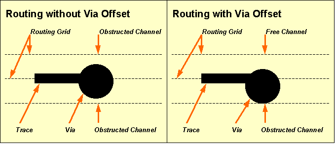
Figure 4-5: Routing with or without Via Offset
The standard trace width is the track width to be used for routing the connections. The standard trace width applies for all nets except for those where certain net attributes are defined. If a
routwidth net attribute value is set for a particular net, then the entire net is routed with that routing width. If a
powwidth value is set for a particular net, then all library-defined power supply pins of that net are connected with that power width. The standard minimum distance sets the default minimum clearance distance to be considered by the
Autorouter when routing the connections. The standard minimum distance applies for all nets, except for those where non-default minimum distance values are assigned with the
mindist net attribute. The
Autorouter automatically performs high priority processing of nets with net attribute values set. The
priority net attribute can be used to specify explicit net-specific routing priorities. See the
loglib utility program description in
chapter 7.11 of this manual for more details on how to use net attributes for controlling the routing process.
The function from the menu is used to specify the number of signal layers to be simultaneously routed by the Autorouter. The signal layer count can range from 2 to 12. The default signal layer count for a particular layout corresponds with the top layer setting of that layout.
The function is used to set the preferred routing direction (horizontal, vertical or all directions) for each routing layer. With the function it is also possible to define trace keepout layers (i.e., layers where routing is prohibited) or to remove layers from the routing layer list (which will decrement the signal layer count). The default layer assignments are horizontal for layer 1, vertical for layer 2, horizontal for layer 3, vertical for layer 4, etc. Changing the routing layer count with function resets the layer assignments.
Routing layer numbering starts with signal layer 1 (solder side). The Autorouter simultaneously routes all routing layers. Single-layer boards can be routed with routing layer count 2 and routing layer 1 defined as prohibited layer.
All objects placed on prohibited layers are considered by the Autorouter. I.e., via keepout areas on a double-sided layout can be defined by placing keepout areas on signal layer 3 of the layout, setting the routing layer count to 3, and defining routing layer 3 to be prohibited. The Autorouter would then use signal layers 1 and 2 for routing the traces and refrain from placing vias at positions where via pads would intersect with keepout areas on layer 3.
The layer assignments (except for the signal layer count) can be changed between different router passes, i.e., without the need of restarting the complete routing process. Note however that restrictions introduced with layer assignment changes will never cause a deterioration of the current routing result at subsequent router passes. I.e., the Autorouter will try to but not necessarily remove all previously routed traces from prohibited layers, if those layers were available for routing before.
Changing layer assignments between different router passes introduces highest flexibility at the routing of complex PCB technologies. Best success at the routing of certain multilayer SMT boards is often achieved when using outside layers (solder and component side) with highest priority for connecting SMD pins to inside signal layers. This can be accomplished with SMD Via Pre-Place passes to be subsequently activated with dynamically adapted layer assignments and increasing routing channel widths (use the and functions to apply single router passes). After completing the SMD Via Pre-Placement some Initial passes (with via and/or channel width restrictions) can be applied to route the signal inside layers only (prohibit the outside layers). Finally the outside layers can be released again for subsequent router passes such as Complete Initial pass, Optimizer, rip-up routing, etc.
The Bartels AutoEngineer is capable of routing up to 12 power layers in addition to the signal layers. I.e., the Bartels AutoEngineer can rout multilayer designs with a total of up to 24 layers. The power layer routing algorithms are equipped with intelligent power plane detection features for split power plane routing. When routing power layers, the Autorouter correctly connects SMD pins to power layers and/or active copper areas defined on such power layers.
The function is used to set the maximum number of vias per circuit trace. The default maximum via count is 20. A maximum via count of 0 forces the Autorouter to rout the layout without vias. The maximum via count can be changed between different router passes, i.e., without the need of restarting the complete routing process. Note however that restrictions introduced with maximum via count changes will never cause a deterioration of the current routing result at subsequent router passes. I.e., the Autorouter will try to but not necessarily remove all previously placed vias.
The function is used to set the grid for placing vias to 1/10 or 1/20 inch. The option is used on default, thus allowing unrestricted via placement according to the current setting (see above). The via grid can be changed between different router passes without the need of restarting the complete routing process. Note however that restrictions introduced with the via grid changes will never cause a deterioration of the current routing result at subsequent router passes, i.e., the Autorouter will try to but not necessarily replace previously placed vias.
The function is used to activate half-grid routing (option ). On default half-grid routing is deactivated (option ). Half-grid routing means that the Autorouter can alternatively use a routing grid shifted by half of the selected routing grid, e.g., half-grid routing with 1/40 inch routing grid can also utilize the 1/80 inch grid routing grid. The current standard trace width and minimum distance settings are not affected by the sub-grid routing option. Half-grid routing yields better use of regions nearby off-grid placed objects such as pin channels at off-grid placed parts, thus considerably increasing routability of dense layouts.
A rule-driven gridless router is integrated to the Autorouter. Gridless routing is deactivated on default (option of the function from the menu). The rule-driven gridless router can be activated through the option from the function. The gridless router performs selective gridless routing, i.e., gridless routing is only applied locally where this yields better results in terms of routability and manufacturing optimization. With gridless routing activated, there are much more options for using off-grid pin channels, which might significantly increase the routability of complex layouts. Gridless routing generates straighter connections to off-grid placed pins, thus preventing from blocking adjacent pin channels and also performing more optimization for manufacturing.
The mode allows for traces to leave the routing grid under virtually any condition and for minimum distance routing between off-grid pins, thus achieving significantly better routing results especially for dense SMT boards.
The mode straightens connections to gridless placed pins and vias only locally and resumes and/or applies gridbased routing for normal traces. This mode is not capable of routing between offgrid placed pins where this otherwise would be possible in mode.
Note that gridless routing requires more main memory and computing power due to additional data structures (gridless priority tree) to be maintained during the routing process.
The function is used to set the trace corner cutting mode. On default trace corner cutting falls on half grid points (option ). The option forces trace corner angles onto the routing grid only, thus ensuring correct spacing between diagonal trace segments and pad corners. Figure 4-6 illustrates the effects of off-grid and on-grid trace corner cutting.
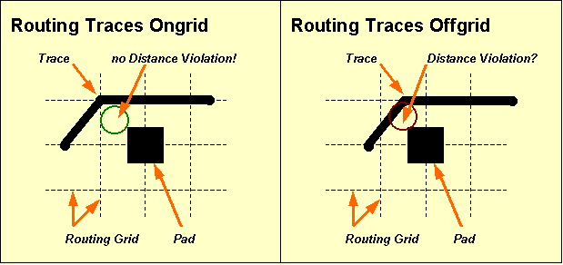
Figure 4-6: Routing Traces Ongrid/Offgrid
The function is used to allow (option , default) or avoid (option ) pin corner routing. This feature works on approximately rectangle-shaped pads and controls whether traces can exit such pads at 45 degree angles or not. Routing with pin corner obstruction can produce better looking layouts, but could also impede 100% routing. Note that connecting pins with a size approximately equal to or smaller than the trace width could fail. The option should not be used with designs that include thick traces. Note also that bus routing can produce unpredictable results when switched to pin corner obstruction.
The menu provides a series of functions for controlling the routing process.
The function is used to set the number of Optimizer routing passes to be automatically activated by the function after obtaining a 100% routing. The Optimizer passes count can range from 0 to 99; 2 Optimizer passes are activated on default.
The function is used to activate (default option ) or deactivate (option ) cleanup passes during rip-up routing. The function is used to activate (default option ) or deactivate (option ) cleanup passes during optimization. When running cleanup passes (note message issued by the routing progress report), the Autorouter makes use of a unique pattern search recognition algorithm for identifying disturbing traces during rip-up and cross-net optimization. The Autorouter is able to select and remove disturbing traces during rip-up and perform cross-net changes during optimization. Cleanup during cross-net optimization requires more computing time, but dramatically reduces via counts and thus is also called if the rip-up router (temporarily) fails to find an acceptable solution. It is recommended to refrain from turning off cleanup when running rip-up on complex designs or optimizing dense boards. Turning cleanup off results in sequential processing of the connections and can produce contenting results when running final Optimizer passes on certain layouts (however, more passes are then required for pushing and/or straightening trace bunches).
The function sets the maximum number of traces allowed to be simultaneously ripped up per rip-up cycle. The rip-up trees number is set to 2 on default, and can range from 1 to 9. The function is used to control the persistence of the rip-up process. A high value will result in higher persistence. The rip-up depth value can range from 1 to 999, and is set to 50 on default. The function sets the maximum number of rip-up retries for routing a particular trace, thus defining the local rip-up router intensity. The rip-up retries number is set to 2 on default, and can range from 0 to 99. Higher rip-up control parameters increase the persistence and intensity of the rip-up routing process, and thus can be used for special problems such as completing 100% routing without intermediate optimizer passes or for routability check.
Once 99.5% routing completion is achieved, the Rip-Up parameters are automatically increased to Rip-Up Trees 6, Rip-Up Level 200 and Rip-Up Retries 10, unless higher values are already set. This helps to avoid the time-consuming Optimizer cleanup passes between Rip-Up passes if only a few open connections are left.
The function is used to activate (option ) or deactivate (default option ) the initial routing algorithm for connecting SMD pins to signal inside layers. With SMD via pre-placement activated the function will start with the SMD via pre-place initial routing pass. The SMD via pre-placer will - as far as possible and/or meaningful - generate short trace connections to vias for those SMD pins to be wired. At SMD fanout routing, routing directions result from the shapes and positions of the corresponding SMD pads; i.e., the SMD fanout routing algorithm ignores layer-specific routing direction preferences to refrain from blocking PLCC/SMD pin channels and or PLCC/SMD pins. The SMD via pre-routing pass is intended for preventing the Autorouter from extensively using the SMD outside layers at an early stage of the routing process, thus involving earlier 100% routing success in a wide range of SMT designs. The SMD via router does not (re-)rout SMD pins which are already connected to fixed traces, and redundant SMD via connections are later eliminated by the Optimizer.
A feature for performing placement optimizations is integrated to the rip-up router of the Autorouter. The menu function can be used to activate (option ) or deactivate (option ) placement optimization during rip-up routing. With , the rip-up router performs pin/gate/groups swaps to increase routability. This can significantly reduce the time required for achieving a 100% autorouting completion. Placement optimization is selective, i.e., swaps with a high potential to simplify the routing problem are carried with higher priority. Swap operations which cause a deterioration of the current routing result rejected by the router's backtracking process. Only unfixed parts are subject to swap operations, and the admissibility of any pin/gate swap is controlled through the corresponding logical library part definitions.
Pin/gate swaps create a backannotation request which triggers automatic when loading SCM plans to the Schematic Editor (see chapter 2.7). requests also prevent the Packager from forward annotation without confirmation (see chapter 3.2.3).
The function is used to activate (default) or deactivate automatic security copy of intermediate routing results.
The menu provides functions for setting routing strategies such as via cost, pin channel cost, packing cost, bus bending cost, dynamic density cost, etc. These settings should be used with care. Only change one or two at a time. Poor routing results are often found to be caused by random strategy parameter settings. The default settings will work best in the vast majority of cases. It is strongly recommended to change strategy parameters in special cases only and to refrain from using extreme values.
There are strong mutual dependencies between different Autorouter strategy parameters. A high via cost value (for eliminating vias) will necessarily result in more ignorance of routing direction preferences, thus compensating the cost factor for keeping preferred routing directions. Note also that strategy parameters only define subordinate options for the Autorouting process, due to the fact that it is much more important to achieve a 100% routing result instead of, e.g., keeping preferred routing directions. I.e., some cost factors may be completely ignored during initial routing and rip-up and will only be considered by the Optimizer. Tabelle 4-2 provides an overview to all of the routing parameters which can be set from the Strategy menu.
Table 4-2: Autorouter Strategy Parameters
| Strategy Parameter | Value Range | Default Value | Effect on Router | Effect on Optimizer |
|---|---|---|---|---|
| Optimize Direction | Normal Preferred Diagonal | Normal | - | x |
| Via Cost | 2..20 | 10 | x | x |
| Pin Channel Cost | 0..10 | 3 | x | - |
| Counter Dir. Cost | 0..5 | 1 | x | x |
| Dir. Change Cost | 0..5 | 2 | - | x |
| Packing Cost | 0..5 | 1 | x | - |
| Dyn. Density Cost | 0..50 | 10 | x | - |
| Bus Bending Cost | 0..5 | 2 | x | - |
| Distance-1 Cost | 0..10 | 5 | x | - |
| Distance-2 Cost | 0..10 | 2 | x | - |
| Trace Cross. Cost | 2..100 | 20 | x | x |
| Diagonal Cost | 0..10 | 5 | - | x |
| Off-Grid Cost | 0..5 | 2 | x | x |
| Prefered Grid | 0..7 | 0 | x | x |
| Anti-Prefered Grid Cost | 0..10 | 1 | x | x |
| Outside Net Type Area Cost (BAE HighEnd) | 0..5 | 1 | x | x |
The function is used to designate the Optimizer strategy. The default option causes the Optimizer to ignore layer-specific preferred routing directions in order to obtain the greatest reduction of vias. The option causes the Optimizer to consider layer-specific preferred routing directions, which could increase the number of vias. The option causes the Optimizer to prefer diagonal (45 degree) routing where appropriate.
The setting is used by the Router and the Optimizer. A high via cost factor results in fewer vias but more complex circuit traces. A low via cost factor permits more vias within the restraint of the maximum via count (see above). The via cost value can range from 2 to 20; the default value is 10.
The setting is used by the Router only. A high pin channel cost factor results in infrequent use of pin channels. A low pin channel cost factor permits the frequent use of pin channels. Pin channels are the regions between adjacent part pins. The pin channel cost value can range from 2 to 20; the default value is 10.
The setting is used by the Router and the Optimizer. A high counter direction cost factor results in strict adherence to the layer-specific preferred routing directions. A low cost factor permits frequent variations from the preferred direction. The counter direction cost value can range from 0 to 5; the default value is 1.
The setting is used by the Optimizer only. A high direction change cost factor results in less circuit corners. A low direction change cost factor permits frequent changes in routing directions. The direction change cost value can range from 0 to 5; the default value is 2.
The setting is used by the Router only. A high packing cost factor results in high bundling of circuit traces. A low packing cost factor will result in wider distribution of circuit traces. The packing cost value can range from 0 to 5; the default value is 1.
The setting is used by the Router only. The dynamic density cost factor controls the global distribution of circuit traces over the entire layout. A high dynamic density cost factor results in a more even distribution of the circuit traces. A low cost factor gives more influence to routing costs. The dynamic density cost value can range from 0 to 50; the default value is 10.
The setting is used by the Router only. The bus bending cost factor controls the bending of traces after passing a pin channel. A high bus bending cost factor results in high priority of bending. A low bus bending cost factor results in less bending. The bus bending cost value can range from 0 to 5; the default value is 2.
The and settings are used by the Router during rip-up.
The rip-up distance-1 cost factor controls the use of channels left by ripped up traces in the near distance (0 to 1 grid point). A high distance-1 cost factor results in less use of these channels, thus forcing more local changes during rip-up and retry routing. The rip-up distance-1 cost value can range from 0 to 10; the default value is 5.
The rip-up distance-2 cost factor controls the use of channels left by ripped up traces in the far distance (2 grid points). A high distance-2 cost factor results in less use of these channels, thus forcing more global changes during rip-up and retry routing. The rip-up distance-2 cost value can range from 0 to 10; the default value is 2.
The is used to set the trace transition cost factor, which is considered by the Router and the Optimizer to control cleanup pattern recognition during multi-net optimization. A high trace crossing cost factor allows for a more complex routing with more traces crossing each other, thus also producing more vias. A low trace crossing cost factor leads to increased (and more time-consuming) analysis during cross-net optimization, thus eliminating more vias. The trace crossing cost value can range from 2 to 100; the default value is 10.
The Optimizer considers the setting on routing layers where the routing option is selected (see function above). A high diagonal routing cost factor causes the Optimizer to use more diagonal routes. A low diagonal routing cost factor results in less diagonal routing. The diagonal cost value can range from 0 to 10; the default value is 5.
The setting is used by the Router and the Optimizer, and is considered when routing with the half-grid option (see above). A high off-grid routing cost factor results in less use of the sub-grid. A low off-grid routing cost factor permits frequent use of the sub-grid. The off-grid routing cost value can range from 0 to 5; the default value is 2.
The parameter is used for setting a prefered routing grid. values range from 0 to 7; 0 switches the prefered grid of, higher values cause the router to pefer the use of every 2nd, 4th, 8th, 16th, 32nd, 64th or 128th grid point. The parameter (value range 1 to 10, default value 1) is used to set a cost factor for routing outside the prefered grid. Prefered grid routing spreads the routing density and takes only effect on layouts with (large) unoccupied areas. Prefered grid routing parameters should be set before the first Autorouter run. Later changes to these parameters require multiple time-consuming optimizer runs. Note also that high cost factors could cause detouring routes.
The strategy parameter is only supported in BAE HighEnd. A high cost factor prevents nets from being routed outside their net-specific routing areas, a low cost factor allows for nets to be routed outside their routing areas more frequently. The net area cost factor can range from 0 to 5; the default value is 1.
The Autorouter supports various routing algorithms and autorouter procedures such as , initial routing, SMD fanout routing, rip-up/retry routing, , re-entrant routing, etc. These routing procedures can be activated from the menu (functions , , , , ), the menu ( function) and the menu (, ). Activating an autorouting procedure after changing basic routing parameters such as signal layer count, routing grid, half-grid option, standard trace width, standard minimum distance, or pin contact mode discards the currently unfixed traces and vias and (re-)routes the layout with changed options.
The autorouting procedures in BAE HighEnd are some 30 percent faster than in BAE Professional. This performance boost is mainly achieved by optimized internal data structures (HighSpeed Kernel) in BAE HighEnd.
The current routing result is displayed graphically and through statistical readouts whilst routing is in progress. The routing process can be stopped at any time by pressing a key, causing the Autorouter to revert to the (currently best) routing result.
The single-pass Initial Router performs signal trace routing considering preferred routing directions, a certain channel width and a maximum via count per two-point connection. The channel width is the maximum permitted deviance from preferred directions. The channel width is specified in routing grid steps. A zero channel width removes the restraints on deviating from the preferred direction, i.e., the entire board area is then released for routing. The maximum via count used by the Initial Router will never exceed the value set with the function from the menu (see above). The Initial Router places traces close together, thus using minimum space in order to leave more room for subsequent traces (trace hugging). The Initial Router also uses advanced techniques of copper sharing where appropriate. The Initial Router processes power layer connections and attributed nets (with non-default routing widths, minimum distance settings and routing priorities) with highest priority.
The Complete Initial Router automatically activates four Initial Router passes to rout all open connections which can be routed without rip-up and retry. With each Initial Router pass the channel width and the maximum via count is increased. The first Initial Router pass runs with maximum via count zero. The last Initial Router pass runs with channel width zero and a maximum via count according to the parameter set with the function from the menu (see above).
The Rip-Up/Retry Router attempts to route all open connections until the board is completely routed. Connections which can be routed without rip-up are routed first. Then the Rip-Up/Retry Router selects and eliminates traces (rip-up) and re-routes them to create space for the unroutes. For this purpose, the router gathers information on dense board areas and increases the cost of routing in such areas. The Rip-Up/Retry Router is supported by a sophisticated array of heuristic strategy parameters. The cost factors can be dynamically adapted to the current routing problem, thus controlling the "price" of strategies such as via placement, routing against preferred directions, using pin channels, etc. It is strongly recommended to refrain from modifying these strategies, unless the routing success is not what would be expected. When changing cost factors, slight adjustments to a few can make significant improvements or make things much worse. The Rip-Up/Retry Router is guarded by a unique backtracking algorithm, which not only prevents from a deterioration of the result or a dead-lock during rip-up or optimization but also is able to exploit a new and/or better routing solution. The Rip-Up/Retry Router automatically activates intermediate Optimizer passes if a single rip-up pass fails to achieve 100% routing success.
The function is used to start a single pass. The usually is applied after 100% routing to optimize the layout for manufacturing. The eliminates redundant vias, smoothes traces and attempts to rout open connections. Channel width zero is used during optimization and the maximum via count is set to the same value as defined with the function from the menu (see above).
is a special initial routing algorithm for connecting SMD pins to signal inside layers. The SMD via pre-placer generates short trace connections to vias for those SMD pins to be wired. With SMD fanout routing passes, a channel width setting is required and routing directions result from the shapes and positions of the corresponding SMD pads. The SMD via pre-routing pass prevents the Autorouter from extensively using the SMD outside layers at an early stage of the routing process. This strategy achieves earlier 100% routing success in a wide range of SMT designs. Redundant via connections created by are later eliminated by the .
The main menu function is used to start a complete Autorouting process including all router passes such as SMD Via Pre-Placement (optionally), complete initial routing, rip-up/retry routing (if necessary) and optimization. This is the standard procedure for performing complete routing of a board. The number of final passes can be set with the function from the menu (see above). The SMD Via Pre-Placer will only be activated if the option has been selected with the function from the menu.
The function from the Standard Autorouter main menu is used to start a routing process with different user-defined router passes. The function is used to schedule up to ten of the following autorouting procedures to be subsequently processed with the function:
| Command | Routing Pass/Procedure |
|---|---|
L | |
F | |
I | |
C | |
R | |
O | |
S | |
- | none (remove router pass from batch) |
pass requires a routing channel width specification and a maximum via count setting. requires a routing channel width specification. requires the number of required passes (up to 999).
The function from the Autorouter menu activates the single net router. The net and/or connection to be autorouted by the single net router can be selected by mouse-clicking some pin or pre-routed trace of the desired net. The single net router is commonly used for pre-routing power supply signals or critical nets with specific preferences for trace widths, clearance, layer assignments, etc.
The function from the menu can be used to rout mouse-selectable parts, i.e., to autoroute all nets connected to the selected component.
The function from the can be used to activate the and function sequence. thus allowing for fully automated layout placement and routing.
The from the menu provides options for controlling net-specific airline display. Nets which are faded-out from airline display are excluded from the autorouting process. Net-specific airline display settings can be changed between router passes. This allows for consecutive router passes to route different groups of nets such as busses of a certain circuit block or signals with certain attributes with specific routing options for preferred routing directions, maximum via counts, etc..
The
Autorouter of
BAE HighEnd considers net-specific routing areas to be defined as documentary areas on signal layers with rule assignments containing a
net_type predicate for the net type. See the
nettype.rul file in the
User Language programs directory
(baeulc) for net type rule definitions. Up to eight different routing area net types can be assigned to each layout. Routing areas and rule assignments (with the
gedrule User Language program) must be defined in the
Layout Editor. Within a routing area, the
Autorouter can only route nets with a matching
$nettype attribute. Nets without
$nettype value or with a
$nettype value different to the
net_type assignment of a certain routing area must not be routed in that area unless they connect to pins inside the routing area. Nets of a certain net type are not restricted to net-specific routing areas, however, they are preferably routed in the corresponding routing areas. Routing outside the net-specific routing area can be controlled with the new
option to be set through the
menu.
You should first start the
Layout Editor and load the layout
board from the
demo.ddb DDB file. The
command from the
Layout Editor
menu is used to call the
Autorouter:
| File |
| Autorouter |
The following operations will show how to apply certain router passes for routing our example job using three signal layers. Use the following commands to set the signal layer count to 3:
| Options |
| Signal Layer Count |
| 3 Signal Layers |
Use the following commands to select 1/40 inch routing grid without via offset, and set the standard trace width and the minimum distance to 0.3mm each:
| Options |
| Routing Grid |
| 1/40 Inch no ofs. |
| Trace Width |
| New Default Trace Width ( 0.32mm) ? | 0.3 |
| Minimum Distance |
| New Minimum Distance ( 0.29mm) ? | 0.3 |
Use the following commands to change trace clipping to 0.1mm and activate the function:
| V|iew |
| Set Clipping |
| Display Traces wider than ( 1.50mm) ? | 0.1 |
| Zoom All |
Use the following commands to define a router batch process consisting of with channel width 4, , and a single pass:
| Autorouter |
| Batch Setup |
| 1: --- |
| New Batch Pass (L/F/I/S/C/R/O/-) ? | s |
| Initial Pass Channel Width ? | 4 |
| 2: --- |
| New Batch Pass (L/F/I/S/C/R/O/-) ? | c |
| 3: --- |
| New Batch Pass (L/F/I/S/C/R/O/-) ? | o |
| Optimizer Passes ? | 1 |
| No Change |
A dash string input ("-") to the prompt can be used to remove the selected router pass from the batch. The sequence of router passes to be processed by corresponds with the sequence of router passes defined with . Use the command to run all router passes previously defined with the function:
| Autorouter |
| Batch Start |
Router batches can also be started with the button from the dialog without having to leave the dialog and subsequently calling the function.
The routing process for our example starts with . Subsequently, a pass is performed. The will end up with 100% routing success. Finally, one pass is activated. Each routing pass automatically saves its routing result. The following message is displayed in the status line after finishing the last pass:
Max. 53 of 53 Routes (Pins: 76, Vias: 5)
The layout is now completely routed with 5 vias placed by the Autorouter.
Use the following commands to run an additional pass (without pattern recognition, but with high priority for considering preferred routing directions):
| Control |
| Optimizer Cleanup |
| Optimizer Cleanup Off |
| Strategy |
| Optimizer Direction |
| Preferred |
| Counter Dir. Cost |
| Counter Direction Cost Factor : 1 (0..5) ? | 4 |
| Autorouter |
| Optimizer |
Note how the pass routes traces according to preferred routing directions, albeit at the price of an increased via count of 13.
You can exit the Autorouter using one of the , or functions from the menu.
exits to the operating system. saves the currently processed layout and returns to the BAE main shell. saves the currently processed layout and returns to the Layout Editor.
Use the function from the menu to return to the Layout Editor:
| File |
| Layout Editor |
Using three routing layers for our simple example appears to be rather wasteful. We want to route the layout again, now with two routing layers instead of three. We also want to apply to keep as much of the current routing result as possible.
Use the following commands to switch back to the Autorouter:
| File |
| Autorouter |
Use the following commands to reduce the signal layer count to 2 and reload the data produced by the preceding router pass:
| Options |
| Signal Layer Count |
| 2 Signal Layers |
| Autorouter |
| Load Traces |
The function fails to load the traces previously routed on layer 3 since the signal layer count is now set to 2. I.e., the router progress message in the status line will indicate 9 open connections (max. 44 of 53 routes) and a via count of 8 (instead of 13) after finishing the function.
Use the following commands to switch off preferred routing direction optimization and start the to complete the routing:
| Strategy |
| Optimizer Direction |
| Normal |
| Autorouter |
| Full Autorouter |
The completes the routing, now on two instead of three signal layers and with 6 vias. Use the following commands to return to the Layout Editor:
| File |
| Layout Editor |
After correctly performing all operations of this chapter, the PCB layout example should look like the one shown in figure 4-7.
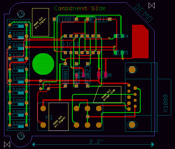
Figure 4-7: Layout after Autorouting
This section describes advanced features and special functions provided with the BAE PCB design system.
The
function from the Layout Editor
menu is used to run a complete design rule check on the currently loaded layout. It is strongly recommended to use
before generating CAM data and/or passing CAM data to the PCB manufacturer to avoid design rule violations such as short-circuits, unrouted nets or clearance violations. Use the following commands to perform a batch design rule check on the currently loaded layout
board of the
demo.ddb DDB file:
| Utilities |
| Batch DRC |
| Please confirm (Y/N) ? | y |
After performing the design rule check, the function implicitly activates the function from the menu to display the checking results and the design state. The function can also be called explicitly using the following commands:
| Utilities |
| Report |
The following listing is displayed by the function or after (zero error lines might be omitted):
File : demo.ddb Type : Layout / Element : board
Number of Nets .................: 22 Number of Open Connections .....: 0 Number of Short Circuits .......: 0 Copper Distance Violations .....: 0 Documentary Distance Violations : 0 Number of Power Layer Errors ...: 0 Number of Missing Parts ........: 0 Number of Wrong Type Parts .....: 0 Number of Missing Netlist Pins .: 0 Height Distance Violations .....: 0 Power Layers in Use.............: - Signal Layers in Use............: 1-2
The report entry displays number of nets defined in the net list of the currently loaded layout. The entry denotes the number of not yet routed (two-point) connections on the currently loaded layout. The entry denotes the number of short-circuits encountered by the Design Rule Check. The entry denotes the number of copper layer clearance distance violations online-encountered by the Design Rule Check on the currently loaded element. The entry denotes the number of clearance distance violations on documentary layers. The entry denotes number of copper area cross-intersections on split power planes. The report entry denotes the number of net list parts not yet placed on the currently loaded layout. The report entry denotes the number of net list parts placed with a wrong part package type (macro) on the currently loaded layout. The entry denotes the number of unplaced and/or missing net list pins. Missing net list pins can cause an erroneous open connections count. An indicator is added to the open connections count if net list pins are missing. The checklnl User Language program can be used to track missing net list pins. The entry denotes the number of (part) height design rule violations. The and report entries display the used power and signal layers. Signal layer 1 to top layer are always assumed to be in use. These entries help to identify power layers without global net assignment, hence with split power planes to be considered by connectivity.
The dialog from the Layout Editor menu provides the parameter for selecting DRC distance and height rule violation error display modes and/or colors. The option displays error boxes using the error color selected with the function, the default of which is white. The setting displays error rectangles using the color selected for the layer on which the erroneous element is placed. Errors on layers which are faded-out through are not displayed.
The Layout Editor menu provides the function for displaying the DRC distance and height rule violation error lists. The DRC errors are listed in a popup menu, indicating error type, error layer and error coordinates for each error. A to the error position ist triggered when selecting an error from the list using the left mouse button. The + and - keys can be used to move the zoom window through the error position list in either direction.
Note that the modified BAE HighEnd data structure for storing the layout connectivity data allows for a selective shortcut display, i.e., shortcuts between two nets are displayed by highlighting only those elements causing the shortcut, whilst BAE Professional highlights the whole connection tree affected by the short-circuit.
Hit the spacebar to return to the Layout Editor menu.
The function from the menu activates a popup menu for modifying the current color settings. This color setup menu simultaneously can be utilized for displaying the current color assignments. Changing some item-specific color is accomplished by selecting the desired display item using the left mouse button and then selecting the desired color button from the function. In the layout system, provides a feature for fast display item fade-out/fade-in. Activating and/or deactivating some item-specific display is accomplished by selecting the desired display item entry with the right mouse button which works as a toggle between fade-out and fade-in. The system won't loose information on currently defined colors of faded-out display items; strike-through color buttons are used for notifying currently faded-out display items.
At overlaps of different elements the resulting mixed color is displayed. The highlight color is also mixed with the color of the element to be marked, thus resulting in a brighter display of that element.
The
function from the
menu is used to save the current color settings with a user-specified name to the
ged.dat system file in the BAE programs directory. When starting the
Layout Editor (or any other layout program module), the color table named
standard is automatically loaded. Any other color table available in
ged.dat can be loaded using the
function from the
menu.
It is a good idea to define color tables for certain tasks such as
stackdef for padstack editing (i.e., with drill holes and drill plan visible) or
unroutes for fast open connections recognition (i.e., with airlines visible only). At the definition of color tables it is to be considered that screen redraw functions will take longer if more objects must be displayed. It is recommended to define task-specific color tables to display only those objects which are important for the corresponding task.
The
function is usually used to allow selection on a specific layer. It also has the useful hidden function of loading a layer-specific color table. These color tables have specific names, and if they don't exist there will be no change in the color display. See
table 4-3 for the color table names assigned to the pick preference layers
(<n> is the layer number, respectively).
Table 4-3 also lists short layer names which can optionally be used in certain layer menus for selecting layers via keyboard input.
Table 4-3: Pick Preference Layer Color Tables and Short Layer Names
| Layer | Pick Preference Layer Color Table Name | Short Layer Name |
|---|---|---|
| Signal Layer <n> | layer_<n> | <n> |
| Signal Layer All Layers | layer_all | a |
| Signal Layer Middle Layers | layer_def | m |
| Signal Layer Top Layer | layer_def | |
| Power Layer <n> | p<n> | |
| Documentary Layer <n> Side 1 | layer_d<n>_1 | d<n>s1 |
| Documentary Layer <n> Side 2 | layer_d<n>_2 | d<n>s2 |
| Documentary Layer <n> Both Sides | layer_d<n>_a | d<n>sa |
| Board Outline | b | |
| Airlines | u |
When selecting a certain pick preference layer (e.g., signal layer 2) using the
function, the color table with the corresponding name (e.g.,
layer_s2) is automatically loaded if available in
ged.dat. This feature is most useful for e.g., manual routing.
The Layout Editor provides functions for performing pin/gate swaps to simplify the routing problem. Alternate package types can be assigned to layout parts, and net list part names can be changed for better legibility of the insertion plan (for manual insertion). These modifications are net list changes which must be backward annotated to the schematics using the function from the Schematic Editor (see also chapter 3.3).
In this section we will apply some pin/gate swaps and change a couple of part names. First of all, use the following commands to set the coordinate display mode to inch and apply group functions to delete all traces from the currently loaded layout:
| Settings |
| Coordinate Display |
| Display Inch |
| Groups |
| Group Polygon |
| Traces |
| Select |
| Move to [0.1",0.1"] |
| Move to [2.8",0.1"] |
| Move to [2.8",2.7"] |
| Move to [0.1",2.7"] |
| Done |
| Delete Group |
The
function from the
menu is used to perform manual pin/gate swaps. Use the following commands to swap the pins
1 and
2 of the switches named
s1000,
s1001,
s1002 and
s1003, respectively:
| Parts |
| Pin/Gate Swap |
| Move to "s1000.1",[0.2",2.3"] |
| Move to "s1000.2",[0.5",2.3"] |
| Pin/Gate Swap |
| Move to "s1001.1",[0.2",2.1"] |
| Move to "s1001.2",[0.5",2.1"] |
| Pin/Gate Swap |
| Move to "s1002.1",[0.2",1.9"] |
| Move to "s1002.2",[0.5",1.9"] |
| Pin/Gate Swap |
| Move to "s1003.1",[0.2",1.7"] |
| Move to "s1003.2",[0.5",1.7"] |
Note how the
function provides graphical pin/gate swap indicators. A circle (0.6mm diameter,
color) is displayed for every pin/gate swap enabled pin when the
function is activated. The indicator for the first selected pin turns into a filled square, leaving only swappable pins marked by circles and character codes for the possible swap operations. The character codes are
P for pin swap,
G for gate swap and
A (Array) for gate group swap. Selecting black for the
color deactivates the pin/gate swap indicator display.
Each pin/gate swap is performed using the corresponding pin/gate swap definition from the Logical Library (see also chapter 7.11 for a description of the loglib utility program and chapter 3.2 for a description of the Packager program module). The following error message is issued if no swap is allowed for the selected pins and/or gates:
Not allowed to swap these pins!
Use the following commands to swap the gates (1,2,3) and (5,6,4) as well as the pins
12 and
13 of the part named
IC10:
| Parts |
| Pin/Gate Swap |
| Move to "ic10.(1,2,3)",[1.4",1.8"] |
| Move to "ic10.(5,6,4)",[1.5",1.8"] |
| Pin/Gate Swap |
| Move to "ic10.12",[1.4",2.1"] |
| Move to "ic10.13",[1.3",2.1"] |
Use the following commands to perform a part swap for the resistor parts named
R101 and
R103 (this is allowed because the same attribute values are assigned to these parts):
| Parts |
| Pin/Gate Swap |
| Move to "r101",[1.6",2.4"] |
| Move to "r103",[1.4",1.2"] |
The
function from the Parts menu is used to change part names in the net list. Use the following commands to change the net list part name of connector
X1000 to
filenameX1, and also change the net list part name of diode
V1000 to
V2:
| Parts |
| Netlist Part Name |
| Move to "x1000",[2.4",1.5"] |
| Part Name (X1000) ? | X1 |
| Netlist Part Name |
| Move to "v1000",[1.2",1.2"] |
| Part Name (V1000) ? | V2 |
The function issues the following error message if you try to assign a part name which is already in use for another part:
Part name already in use!
Use the following commands to apply the
function to change the name of part
IC10 to
IC1:
| Parts |
| Change Part Name |
| Move to "ic10",[1.2",1.8"] |
| Part Name (IC10) ? | IC1 |
The airlines previously connected to
IC10 have been disappeared from
IC1. I.e., the
function not only performs a part name change, but also replaces the selected part. With the commands above the part named
IC10 has been replaced with the part
IC1 which is not defined in the net list. Use the following commands to reset this part name change and apply the
function to change the net list part name to
IC1 (note how the airlines connected to
IC1 will appear again):
| Parts |
| Change Part Name |
| Move to "ic1",[1.2",1.8"] |
| Part Name (IC1) ? | ic10 |
| Netlist Part Name |
| Move to "ic10",[1.2",1.8"] |
| Part Name (IC10) ? | ic1 |
It is recommended to use the function with caution. Multiple misuse of the function can cause short circuits on routed layouts, and it might get very laborious to backtrack part name changes for design corrections.
The layout net list changes accomplished with the previous operations must be backannotated to the schematics and the logical net list. Use the following commands to save the currently loaded layout and return to the BAE main menu:
| File |
| Save Element |
| File |
| Main Menu |
The BAE main menu is activated. Use the following commands to switch to the
Schematic Editor and run
to transfer the physical net list named
board in in
demo.ddb back to the schematics:
| Schematic |
| Utilities |
| Backannotation |
| Design File Name ? | demo |
| Layout Element Name ? | board |
displays the following messages:
============================== BARTELS BACKANNOTATION UTILITY ==============================
Design File Name ........: 'demo' Layout Element Name .....: 'board' No error occurred!
The
message means that
has been successfully completed, and the logical net list in project file
demo.ddb has been annotated with the physical net list named
board. Hit any key to return to the
Schematic Editor main menu and use the following commands to load the SCM sheet
sheet1 from DDB file
demo.ddb:
| File |
| Load |
| Sheet |
| File Name ? | demo |
| Element Name ? | sheet1 |
You can now examine the currently loaded SCM sheet for modifications introduced by
. Particularly note the part name changes
(IC1 instead of
IC10,
V2 instead of
V1000, etc.) and the pin assignment changes (e.g., at the gates of
IC1 or at the switches
S1000 through
S1003).
Bartels AutoEngineer provides features for modifying SCM sheets of an already completed design, without the need to prepare a completely new layout. This section describes how perform a redesign by making changes to the currently loaded SCM sheet.
Use the following commands to change the
$plname attribute value of the resistor
R104 from
minimelf to
chip1206:
| Symbols |
| Assign Value |
| Move to "r104",[210,130] |
| $plname |
| Attribute Value ? | chip1206 |
| Return |
With the commands above the package type assignment for the resistor part
R104 has been changed. Use the following commands to assign value
so14 to the
$plname attribute of each gate of part
IC1, thus defining a non-default package type for
IC1 (the default package type was
dil14):
| Symbols |
| Assign Value |
| Move to "ic1.5",[60,110] |
| $plname |
| Attribute Value ? | so14 |
| Assign Value |
| Move to "ic1.1",[100,110] |
| $plname |
| Attribute Value ? | so14 |
| Assign Value |
| Move to "ic1.8",[140,110] |
| $plname |
| Attribute Value ? | so14 |
| Assign Value |
| Move to "ic1.13",[180,110] |
| $plname |
| Attribute Value ? | so14 |
Use the following commands to save the currently loaded SCM sheet and load
sheet2:
| File |
| Save |
| Load |
| Sheet |
| File Name ? | |
| Element Name ? | sheet2 |
The currently loaded SCM sheet contains some
Autorouter control parameter settings (net attribute assignments), which should be modified. Use the following commands to change the
ROUTWIDTH net attribute of
NET from 0.5mm to 0.3mm, change the
ROUTWIDTH attribute of net
Vss from 0.6mm to 0.45mm and change the
MINDIST attribute for net
Vdd from 0.4mm to 0.3mm:
| Symbols |
| Assign Value |
| Move to "NET"/Routwidth Symbol |
| $val |
| Attribute Value ? | 0.3 |
| Assign Value |
| Move to "Vss"/Routwidth Symbol |
| $val |
| Attribute Value ? | 0.45 |
| Assign Value |
| Move to "Vdd"/Mindist Symbol |
| $val |
| Attribute Value ? | 0.3 |
Use the following commands to return to the BAE main menu (the currently loaded SCM element is automatically saved):
| File |
| Main Menu |
Now the BAE main menu is activated. Use the following commands to run the
Packager to transfer the SCM changes to the layout, i.e., to the physical net list named
board (the
demo.ddb job file can be used as design library since it contains all of the information required for packaging):
| Packager |
| Design File Name ? | demo |
| Design Library Name ? | demo |
| Layout Element Name ? | board |
The Packager issues the message after successfully completing the forward annotation to the layout. Hit any key to return to the BAE main menu and use the following command to start the Layout Editor:
| Layout |
Now the Layout Editor is activated. Use the following commands to load the annotated layout:
| File |
| Load Element |
| Layout |
| File Name ? | demo |
| Element Name ? | board |
A connectivity generation is accomplished after loading the layout. Note that there are no airlines connected anymore to the parts
IC1 and
R104, since the package types have been changed for these parts. Use the following commands to delete all parts with changed package type assignments introduced by net list modifications:
| Parts |
| Delete Update |
| Please confirm (Y/N) ? | y |
The confirm prompt is only activated if there are parts placed with wrong package types. The
function can be used for checking the layout for wrong package types (simply type
n to the confirm prompt if you want to abort the
function). The
call from above deletes the parts
R104 and
IC1 from the layout and issues the following message:
2 Parts deleted!
Use the following commands to place the previously deleted parts with correct package types:
| Parts |
| Add Part |
| Part Name ? | ic1 |
| Jump Absolute |
| Absolute X Coordinate (mm/") ? | 1.6" |
| Absolute X Coordinate (mm/") ? | 2.0" |
| Place Next Part |
| Mirror On |
| Rotate Right |
| Jump Absolute |
| Absolute X Coordinate (mm/") ? | 0.35" |
| Absolute Y Coordinate (mm/") ? | 2.0" |
Now all parts are placed again on the layout. You can check this with the function which should issue the message.
The
Bartels AutoEngineer layout system provides features for defining power layers and/or power planes. Use the following commands to define a power layer for signal
Vss:
| Settings |
| Set Power Layers |
| 1: --- |
| Net Name ? | vss |
| End |
Note how the above-mentioned power layer definition removes the airlines connected to the drilled pins of signal
Vss. Drilled pins are automatically connected to the corresponding power layer (i.e., the
CAM Processor will later generate heat traps at the drillings of power layer pins). The airlines connected to the SMD pins of signal
Vss won't be deleted, i.e., the
Autorouter will automatically connect these pins to the power layer using vias.
Power layer definitions can be displayed in the BAE layout system. Use the following commands to set the color for power layer 1 to dark blue:
| Change Colors |
| Power 1 |
| Move to Desired Color, dark blue |
| Exit |
On the display of drilled pin definitions there is a distinction whether the pin is connected to a power layer or not. Power layer connections are displayed as circle outlines; isolations, i.e., drills which are not to be connected to any power layer, are displayed as filled circles.
The layer selection menus of the
function from the
menu allow for the selection of power layers. Power planes or isolated areas (net name
-) can be placed on power layers to perform split power plane editing, i.e., to define more than one signal on a single power layer. Power planes are displayed with their outlines which will later be interpreted as isolation line by the
CAM Processor (see also
chapter 4.7.6 of this manual). There is a restriction that no power plane can overlap any other power plane partially since this would cause an ambiguity in the power plane tree detection algorithms. Partial power plane overlaps will cause the design rule check to issue power layer errors; the number of power plane errors detected by the DRC is shown with the
entry of the
function. Power planes completely enclosed by other power planes are allowed; the power plane tree detection will always match the "innermost" power plane for connecting.
The layer selection menus of the function from the menu allow for the selection of power layers. Text can be placed on power layers to add documentary information to the power layers. When placing text on power layers, the design rule check will perform distance checking against the and signal layers. Power layer text is visible on the PCB only if the corresponding power layer is configured as board outside layer (i.e., as either solder side or component side layer). Usually power layers are defined as board inside layers of a multilayer design. Text placed on power layers can serve as control information (e.g., for the layout designer or as plot or film archive information).
There is often the need to define areas where the Autorouter is allowed to rout traces but must not place vias (e.g., underneath special parts). Via keepout areas can be defined on a routing layer which is not required for the real layout. This "via keepout layer" should then be prohibited with the Autorouter layer assignment. The Autorouter considers all objects placed on prohibited layers, and vias and/or via drill holes are assumed to be defined on all layers. I.e., the Autorouter refrains from placing vias at positions where via pads would intersect with keepout areas on prohibited routing layers.
Use the following commands to place a keepout area on layer 3 matching the region underneath the switches
s1000 through
s1009:
| Areas |
| Add Keep Out Area |
| Layer 3 |
| Move to [0.25",0.4"] |
| Move to [0.45",0.4"] |
| Move to [0.45",2.4"] |
| Move to [0.25",2.4"] |
| Done |
Use the following commands to start the Autorouter (the currently loaded layout will automatically be saved):
| File |
| Autorouter |
Use the following commands to define routing layer 3 to be prohibited and start the (the Autorouter options such as routing grid, trace width, clearance, etc., have already been defined with the previous Autorouter session):
| Options |
| Layer Assignment |
| Select Layer Number ? | 3 |
| Select Layer Type (P/H/V/A/-) ? | p |
| Select Layer Number ? | |
| Autorouter |
| Full Autorouter |
The
will a find 100% routing solution with no vias placed inside the via keepout area. Note also how the SMD pins of the previously defined power layer
Vss (see above) are automatically connected using short traces with vias.
Use the following command to return to the Layout Editor after successfully completing the autorouting:
| File |
| Layout Editor |
The function from the Layout Editor menu is used to set special display attributes for selectable areas. The option is the default display mode for any area. defines the selected area to be always visible. The option defines the selected area to be visible only when unmirrored (i.e., when placed on the component side). The option defines the selected area to be visible only when mirrored (i.e., when placed on the solder side). The function can be used on part, padstack and pad level. It is possible to define SMD parts with differently shaped pads or keepout areas depending on which side of the board the part is placed (for supporting different soldering processes on solder and/or component side).
Use the following commands to load the pad symbol
p1206 from the
demo.ddb DDB file:
| File |
| Load Element |
| Pad |
| File Name ? | demo |
| Element Name ? | p1206 |
There is finger-shaped contact area defined on the currently loaded
p1206 pad. Use the following commands to define this copper area to be visible only when unmirrored (i.e., when placed on the component side):
| Areas |
| Mirror Display |
| Move to Area Edge |
| Visible unmirrored |
Now the component side pad shape is defined. Use the following commands to define a rectangle-shaped passive copper area to be visible only when mirrored (i.e., when placed on the solder side):
| Areas |
| Add Passive Copper |
| Jump Absolute |
| Absolute X Coordinate (mm/") ? | 0.6 |
| Absolute Y Coordinate (mm/") ? | 0.9 |
| Jump Relative |
| Relative X Coordinate (mm/") ? | -1.2 |
| Relative Y Coordinate (mm/") ? | 0 |
| Jump Relative |
| Relative X Coordinate (mm/") ? | 0 |
| Relative Y Coordinate (mm/") ? | -1.8 |
| Jump Relative |
| Relative X Coordinate (mm/") ? | 1.2 |
| Relative Y Coordinate (mm/") ? | 0 |
| Done |
| Areas |
| Mirror Display |
| Move to Area Corner/Edge |
| Visible mirrored |
Use the following commands to save the currently loaded pad symbol and re-load the layout:
| File |
| Save Element |
| Load Element |
| Layout |
| File Name ? | |
| Element Name ? | board |
The system accomplishes a connectivity generation to correlate the library modifications with the current net list definition. The
p1206 pad is used on the
s1206 padstack symbol, which, in turn, is used on the
chip1206 part symbol. Note how the layout system uses different pad shapes for the mirrored parts
R104 and
C101 and for the unmirrored part
R105.
The function can be applied on any copper, keepout or documentary polygon defined on a library element which can be mirrored. You can also use this feature to define part keepout areas on documentary layers to perform different part clearance checks depending on which side of the board the parts are placed.
A control for setting the parameter is provided in the dialog from the menu to support reflow-reflow SMD/SMT soldering techniques. On default, the parameter is activated, and polygons with the , attribute are only visible when not mirrored, whilst polygons with the attribute are only visible when mirrored. However, with the , parameter deactivated, all polygons declared as , are always visible, and all polygons declared as , are never visible, independently of any (part) mirroring. , deactivation allows for SMD libraries designed for conventional SMD soldering to be re-used for reflow-reflow SMD soldering.
The BAE layout system provides powerful automatic copper fill functions with user-definable minimum structure size and isolation distance. The copper fill algorithm support isolated copper area elimination and automatic heat trap generation with adjustable connection widths and heat-trap-specific isolation distances.
The copper fill functions are available through the submenu of the Layout Editor menu.
Depending on the current BAE menu setup, copper fill parameters can either be set from the dialog of the submenu or through dedicated menu functions in that same menu.
The
function is used to set the copper fill isolation distance parameter for the copper fill algorithm (default 0.3mm). The copper fill clearance distance is applied on default unless some net-specific minimum distance settings are defined through
MINDIST net attributes (see
chapter 7.11). Net-specific minimum distance attribute settings are considered individually.
The function is used to define the minimum structure size for area generation (default 0.1mm). This value should correspond with the smallest Gerber aperture size to ensure valid Gerber photoplot data generation without overdraw errors.
The option of the function causes the copper fill algorithm to generate arc-shaped concave area borders during trace segment isolation; on default octagonal circle interpolation is applied (option ).
The option of the function switches off isolated copper area recognition (i.e., the copper washes over the pad that it is to connect to); on default, isolated copper areas are automatically eliminated during active copper generation (option ). The option keeps isolated areas and automatically selects them to the current group as they are created.
The options also support for different processing modes for pins and vias. It is possible to decide whether heat-trap connections should be generated for both pins and vias (option ), for pins only (option ), for vias only (option ), or if direct connections only should be generated (option ).
The option of the function deactivates automatic heat trap generation when filling active copper. The default option is used to activate automatic heat trap generation, i.e., to create thermal relieves for copper area connections. With selected, the system prompts for the heat-trap junction width and an optional heat-trap-specific clearance distance, where invalid inputs won't change current settings. On default, the heat trap junction width is set to 0.3mm and the heat-trap clearance is set to zero (i.e., heat-traps are isolated using standard minimum clearance settings).
BAE HighEnd provides the option for specifying the maximum heat-trap connections count (1, 2, 3 or 4). The default heat-trap generation sequence is left, right, bottom, top.
Copper fill workareas are required for copper fill functions to operate. Use the following
Layout Editor commands to define a rectangle-shaped copper fill workarea on layer 1 for the signal named
net:
| Areas |
| Copper Fill |
| Add Cop.-Fill Area |
| Net Name ? | net |
| Layer 1 |
| Move to [0.6",0.4"] |
| Move to [1.7",0.4"] |
| Move to [1.7",1.7"] |
| Move to [0.6",1.7"] |
| Done |
A dash string input
(-) to the net name prompt of the
function creates a copper fill workarea which is not assigned to any net. This feature can be used for generating pure shielding areas.
Passive copper areas with signal net connections (e.g., teardrops created as passive copper) are treated like active copper areas of that net and won't be isolated from copper fill areas of that net.
The , , and functions are used to activate automatic copper fill procedures. performs automatic copper fill on all copper fill workareas. deletes copper areas from all copper fill workareas. With and , the user is expected to select the desired copper fill workarea.
Use the following commands to set the isolation distance to 0.35mm, specify a minimum structure size of 0.15mm, deactivate the automatic isolated copper area elimination and fill the predefined workarea:
| Areas |
| Copper Fill |
| Set Fill Clearance |
| Copper Clearance Distance ( 0.30mm) ? | 0.35 |
| Min. Fill Size |
| Min. Fill Structure Size ( 0.10mm) ? | 0.15 |
| Insol. Area Mode |
| Keep Islands |
| Fill single area |
| Move to Copper Fill Workarea |
The system fills the selected workarea with active copper assigned to the signal named
net and isolated from other signal levels. The copper fill process is very laborious and might last a few moments to complete. You should perform a screen redraw and examine the results after the copper fille procedure is completed. You can reset the copper fill, change the copper fill parameters and re-apply the copper fill function if you are not satisfied with the results (maybe because of either too small or too large structures being generated).
Use the following commands to reset the copper fill from above and re-apply the copper fill with automatic isolated area generation:
| Areas |
| Copper Fill |
| Clear single area |
| Insol. Area Mode |
| Delete Islands |
| Fill all areas |
The minimum structure size (i.e., the smallest area size to be generated with copper fill) has basic meaning for subsequent CAM Processor. The copper fill algorithm uses the minimum structure size for automatically rounding off convex corners to avoid acute-angled areas. You should specify the minimum structure size according to the size of the smallest round aperture defined for Gerber output to ensure that Gerber photoplot data can be generated without overdraw errors (see also chapter 4.7 of this manual).
The CPU time and memory requirements of the copper fill algorithm strongly depend on the quantity and complexity of the structures to be isolated and/or generated. Orthogonal structures make the job much easier than e.g., arc-shaped objects since a lot more time consuming geometric distance calculations and complex floating point operations are required for the latter. Figure 4-8 elucidates how the complexity of the objects to be isolated and particularly their mutual positioning strongly affects memory requirements during copper fill. Note, however, that figure 4-8 does not show what large amount of temporary data is required for the area reduction and expansion algorithms used for generating correct copper fill areas. Defining more smaller copper fill workareas instead of a few large ones can often be the workaround when running into memory problems using the copper fill function on main memory limited PC systems.
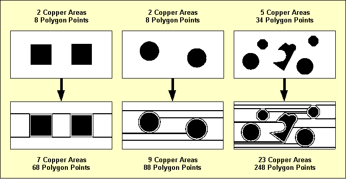
Figure 4-8: Automatic Copper Fill Complexity
You can use one of the , and options instead of the default option from the function to reduce the complexity and number of fill areas. This allows for trace corners and/or full circles to be isolated like octagons, thus also reducing the amount of Gerber data if no Gerber arc commands can be used.
To avoid long response times after unintentionally activating the copper fill function, automatic copper fill can be canceled by pressing any key and confirming the abort request with a verification menu. Note, however, that canceling is not possible anymore at the final stage of connectivity generation, and that areas generated before the abort request must be explicitly eliminated using the function.
Using the copper fill function considerably increases the number of copper areas and polygon points. This raises the CPU time requirements for the function if the function type is set to a corner to corner airline calculation (see chapter 4.3.2 of this manual). In such cases it can be worthwhile to use a pin to pin calculation method to reduce CPU time requirements. The from the Layout Editor menu is used to set the function type.
The submenu provides the function for transforming copper areas into line or cross hatched areas with user-definable hatching width and hatching clearance.
Hatching is accomplished through trace segments generation. The width of the produced trace segments can be set with the function (default 0.3mm) whilst the spacing between produced trace segments can be set with the function (default 1/20 inch).
The function is used to designate the hatching type. The default option generates hatch areas with diagonal trace segments. The option generates hatch areas with crosswise intersecting diagonal trace segments.
The hatching process is activated by calling the function and selecting the copper area to be hatched.
Use the following commands to set the coordinate display mode to inch, and transform the circle-shaped copper area on signal layer 2 of the layout to a line-hatched area with a hatching distance of 1mm:
| Settings |
| Coordinate Display |
| Display Inch |
| Areas |
| Copper Fill |
| Hatching Distance |
| Hatching Line Spacing ( 1.27mm) ? | 1 |
| Hatch Copper Area |
| Move to Passive Copper Area/Signal Layer 2, [0.8",1.8"] |
Use the following commands to set the hatching width to 0.2mm and transform the active copper area (signal
vdd) on signal layer 1 of the layout into a cross-hatched area:
| Areas |
| Copper Fill |
| Hatching Width |
| Hatching Line Width ( 0.30mm) ? | 0.2 |
| Hatching Mode |
| Grid Hatching |
| Hatch Copper Area |
| Move to Active Copper Area "vdd"/Signal Layer 1, [2.5",2.0"] |
The function generates a special layout polygon type called hatched copper area. The hatching and the hatching area outline are generated using traces with a trace width according to the hatching width setting. The traces are strongly connected with the hatched copper polygon to support general Layout Editor polygon functions such as or .
The PCB layout example should now look like the one shown in figure 4-9 if you correctly executed all operations.
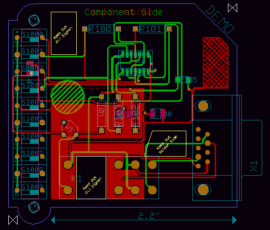
Figure 4-9: Layout with Filled Copper Areas
This might be a good time to save the layout:
| File |
| Save Element |
The function is one of the most powerful features of the Bartels AutoEngineer. is usually used to update a job-specific library in order to correlate it with the contents of some master library.
Use the following commands to copy the currently loaded layout to the
democopy.ddb DDB file (with default layout element name), and load the copied layout:
| File |
| Save Element As |
| File Name ? | democopy |
| Element Name ? | |
| Load Element |
| Layout |
| File Name ? | democopy |
| Element Name ? | |
Now the copied layout appears on the screen. However, this layout contains only those objects which are directly defined on the layout. The lower level library elements (parts, padstacks, pads) are not displayed since they have not been copied with the
function to prevent from overwriting existing library elements in the
democopy.ddb destination file. The system will issue either the
Connected pins missing!
message or the
Cannot load all elements (display not complete)!
message in the status line. Use the following commands to correlate the job-specific library of DDB file
democopy.ddb with the contents of DDB source file
demo.ddb:
| File |
| Update Library |
| Layout |
| File Name ? | |
| Element Name ? | |
| Source File Name ? | demo |
After a few moments the system should issue a message which means that all library elements referenced from the currently loaded layout have been copied from the specified library source file. Use the following commands to re-load the layout in order to display the library update ( works on DDB file level, it doesn't affect elements in main memory):
| File |
| Load Element |
| Layout |
| File Name ? | |
| Element Name ? | |
The
function can also be used to correlate the job-specific library with the contents of a different layout library file. Use the following commands to perform a library update for the currently loaded layout using the library source file
demolib.ddb, and re-load the layout (note how the
r04a25 resistor package type is updated with the definition from
demolib.ddb):
| File |
| Update Library |
| Layout |
| File Name ? | |
| Element Name ? | |
| Source File Name ? | demolib |
| Load Element |
| Layout |
| File Name ? | |
| Element Name ? | |
The
function is used for substituting selectable library elements with definitions from a certain library source file. Use the following commands to replace the
r04a25 part symbol and the
p1206 pad symbol of the current
democopy.ddb DDB file with the corresponding definitions from the
demo.ddb DDB file, and re-load the layout
( works on DDB file level, it doesn't affect elements in main memory):
| File |
| Replace Element |
| Part |
| File Name ? | |
| Element Name ? | r04a25 |
| Source File Name ? | demo |
| Please confirm (Y/N) ? | y |
| Replace Element |
| Pad |
| File Name ? | |
| Element Name ? | p1206 |
| Source File Name ? | demo |
| Please confirm (Y/N) ? | y |
| Load Element |
| Layout |
| File Name ? | |
| Element Name ? | |
The function from the menu is most useful for certain applications such as high frequency design, where net list data is requested to be automatically generated from the copper located on the PCB.
The mode of operation of this function should be demonstrated using the currently loaded layout from DDB file
democopy.ddb. Delete the trace which connects the pins
NO1 and
4 of the parts named
K1 and
X1, and reset the definition of power layer
vss:
| Traces |
| Delete Trace |
| Move to Trace,e.g.[2.35",0.9"] |
| Settings |
| Set Power Layers |
| 1: vss |
| Net Name ? | - |
| End |
Note how the deleted trace and power layer definition are replaced with airlines. Use the following commands to add a trace to connect the pins
2 and
1 of the parts named
R100 and
R101:
| Traces |
| Add Trace |
| Move to "R100.2",[1.4",2.4"] |
| Move to "R101.1",[1.6",2.4"] |
| Done |
The system now indicates a short-circuit error. Use the following commands to save the layout, run to generate a net list with the same file and element name, and immediately re-load the layout again ( stores to DDB file without changing the currently loaded net list data):
| File |
| Save Element |
| Utilities |
| Back Netlist |
| File Name ? | |
| Element Name ? | |
| File |
| Load Element |
| Layout |
| File Name ? | |
| Element Name ? | |
Now the system performs a connectivity generation to correlate the layout with the net list which was previously generated with . Note that there are no airlines displayed anymore after completing the connectivity generation. The layout does not contain any open connections and/or short-circuits anymore (you can check this with and from the menu). Deleting the trace which was previously causing a short-circuit would now result in an airline display.
Another useful application of the function net list generation from Gerber data which was previously loaded with the CAM View module (for more details see chapter 4.8 of this manual).
Blind and buried vias are partial vias which can be used for layer changes when routing multilayer layouts. Routing with blind and buried vias can considerably increase the routability of multilayer layouts with four or more signal layers.
The BAE
Layout Editor features arbitrary pad layer assignment (see also
chapter 4.2.2 for more details on creating padstacks) and drill classes to support the definition of blind and buried vias. Drill classes should be assigned to certain layer-sets to support CAM drill data output for selectable layer-sets (see also
chapter 4.7 for more details on drill data output). There are no system-imposed restrictions on how to define and/or assign drill classes. You can, e.g., use drill class
A for layer-set 1-2, drill class
B for layer-set 2-3, drill class
C for layer-set 3-4, etc. Note, however, that the drill class assignment must be considered for correct drill data output by the
CAM Processor, and that the layout top layer setting (see also
chapter 4.3.1) gains special meaning when using blind and buried vias.
A typical configuration for 4-layer layouts is the definition of the vias
via (for all layers),
via_12 (for layer-set 1-2),
via_23 (for layer-set 2-3) and
via_34 (for layer-set 3-4). All these vias are simultaneously available for routing when selected to the via list (see also
chapter 4.3.4 for details on how to select vias)
The Layout Editor command used during interactive routing automatically selects the via with the least possible layer occupancy. The same principle is applied by the Autorouter. At least one via for all signal layers required for autorouting. Additionally, the Autorouter can e.g., simultaneously use vias for the layer-sets 1-2-3, 1-2, 2-3, etc. However, to avoid backtracking ambiguities, the Autorouter is restricted in that it can not use vias with multiple mutually intersecting layers. I.e., the Autorouter refuses to use a via for layer-set 1-2-3 and another via for layer-set 2-3-4 at the same time (error message ).
Using the CAM Processor for generating drill data output for the drill holes defined on partial vias requires corresponding drill class(es) to be specified.
The production of PCBs with blind and buried vias is usually more expensive than the production of standard multilayer boards. However, using blind and buried vias increases the routability of multilayer layouts and also supports advanced PCB manufacturing technologies such as plasma-etched via production processes.
Don't forget to save the currently edited layout element before exiting the Layout Editor:
| File |
| Save Element |
The following commands can be used from each program module of the BAE layout system (except for the Autorouter) to return to the BAE Main Menu (BAE Shell):
| File |
| Main Menu |
The function automatically saves the currently loaded layout element. From the BAE Shell, the following command can be used to return to the operating system:
| Exit BAE |
The following commands can be used from each program module of the BAE layout system to return to the operating system, i.e., to exit the Bartels AutoEngineer:
| File |
| Exit BAE |
The function activates a confirmation request if the currently loaded element has not yet been saved. In this case you should abort the function, save the current element, and then call again, as in:
| File |
| Exit BAE |
| Please confirm (Y/N) ? | n |
| File |
| Save Element |
| File |
| Exit BAE |
Before starting the CAM Processor for generating real project manufacturing data, you should always perform a complete design rule check using the function from the Layout Editor menu. Subsequently the DRC result should be examined with the function. It is strongly recommended to refrain from generating and/or releasing any CAM Processor output if clearance violations, short circuits or open connections are indicated since this will (almost certainly) result in the production of faulty PCBs.
It is recommended to start the Bartels AutoEngineer from in the directory where the design files should be generated since this considerably simplifies job file access. If you intend to process the examples provided with this manual it is recommended to move to the BAE examples directory installed with the BAE software. The Layout Editor can be called from the Bartels AutoEngineer main shell. Start the BAE shell by typing the following command to the operating system prompt:
> bae
Move the menu cursor to the Layout menu item and confirm this choice by pressing the left mouse button:
| Layout |
Now the Layout Editor program module is loaded and the Layout Editor menu is activated. If this fails to happen then check your BAE software installation (see the Bartels AutoEngineer® Installation Guide for details on how to perform a correct installation).
Use the command from the Layout Editor menu to call the CAM Processor:
| File |
| CAM Processor |
If a layout element was previously processed in the
Layout Editor, then this element will automatically be saved and re-loaded to the
CAM Processor. Within the
CAM Processor the
function from the
menu is used to load layout elements of any hierarchy level. Use the following commands to load the layout named
board from DDB file
demo.ddb:
| File |
| Load Element |
| Layout |
| File Name ? | demo |
| Element Name ? | board |
The system issues the
error message, if the font used in the loaded element is not available in the
ged.fnt font file from the BAE programs directory.
Without character font data, the CAM Processor fails to plot any text defined on the currently loaded layout element. You should either supply the requested character font (e.g., use the fontconv utility program) or assign an existing font to the layout element using the function from the Layout Editor menu before producing any CAM output.
The CAM Processor standard/sidemenu user interface provides a menu area on the right side, consisting of the main menu on top and the currently active menu below that main menu. After entering the CAM Processor the menu is active and the menu cursor points to the function.
The Windows and Motif versions of the
CAM Processor can optionally be operated with a pull-down menu user interface providing a horizontally arranged main menu bar on top. The
WINMENUMODE command of the
bsetup utility program is used to switch between
SIDEMENU and
PULLDOWN Windows/Motif menu configurations (see
chapter 7.2 for more details).
The following main menu is always available whilst processing layout data with the CAM Processor:
| Display |
| Control Plot |
| Gerber Photoplot |
| Drilling+Insertion |
| Plot Parameters |
| Utilities |
The or menu can either be activated by selecting the corresponding main menu item or by pressing the middle mouse button. The or menu provides useful functions for changing display options such as zoom window, zoom scale, input grid, color settings, etc.
The menu provides the functions for generating HP-GL pen plots, PCL HP-laser prints and Postscript output.
The menu provides the functions for generating Gerber photo plots, also including facilities for defining and managing Gerber aperture tables.
The menu provides the functions for generating drill data output (format Sieb&Meier and/or Excellon ) and insertion data output (generic format).
The menu is used to set general plot parameters (plot tolerance, CAM origin, CAM rotation, CAM mirror mode) and to define special parameters for generating negative power layer plots. The menu also provides features for controlling the processing of special layers such as the , , and layers.
The menu provides functions for exiting BAE, returning to the BAE main shell, calling the Layout Editor and starting User Language programs. The menu can also be used for loading layout elements, listing DDB file contents, setting the display grid and the coordinate display mode, or removing error markers.
The BAE software comes with User Language programs for activating a modified CAM Processor user interface with many additional functions (startups, toolbars, menu assignments, key bindings, etc.). The bae_st User Language program is automatically started when entering the CAM Processor. bae_st calls the uifsetup User Language program which activates predefined CAM Processor menu assignments and key bindings. Menu assignments and key bindings can be changed by modifiying and re-compiling the uifsetup source code. The hlpkeys User Language program is used to list the current key bindings. With the predefined menu assignments of uifsetup activated, hlpkeys can be called from the function of the menu. Menu assignments and key bindings can be listed with the uifdump User Language program. The uifreset User Language program can be used to reset all currently defined menu assignments and key bindings. uifsetup, uifdump and uifreset can also be called from the menu of the keyprog User Language program which provides additional facilities for online key programming and User Language program help info management.
The Windows and Motif pulldown menu user interfaces of the CAM Processor provide facilities for cascading submenu definitions. I.e., submenus can be attached to other menu items. The uifsetup User Language program configures cascading submenus for the pulldown menu interfaces of the Windows/Motif CAM Processor modules. This allows for easy submenu function location (and activation) without having to activate (and probably cancel) submenus. The function repeat facility provided through the right mouse button supports cascading menus to simplify repeated submenu function calls.
The following Windows/Motif parameter setup dialogs are implemented for the CAM Processor:
The uifsetup User Language program replaces the parameter setup functions of the Windows and Motif pulldown menus with the above menu functions for activating the corresponding parameter setup dialogs.
When using pulldown menus under Windows and Motif, the uifsetup User Language program configures the following modified CAM Processor main menu with a series of additional functions and features:
| File |
| View |
| Control Plot |
| Gerber Photoplot |
| Drilling+Insertion |
| Settings |
| Utilities |
| Help |
The CAM Processor provides an in-built feature for automatically saving important operational and plot parameters with the currently processed layout and/or part symbol. The following parameters are stored to the current design file when changing to the BAE main menu or to the Layout Editor (i.e., CAM parameter backup can only be suppressed when exiting BAE):
Parameter sets are stored with special names according to the currently processed layout database hierarchy level. The layout element name is used for layout elements, parameter set name
[part] is used for layout part symbol elements,
[padstack] is used for layout padstack elements and
[pad] is used for layout pad elements. When loading an element, the corresponding parameter set is automatically loaded as well, thus providing a convenient way of activating a default parameter set suitable for processing the selected design and/or library element type.
The
functions from the
and
menus are used to specify the CAM data output device. The output can either be written to a file, or directly to the plotter and/or printer. When plotting to a file, the desired output file name must be specified. When writing directly to the plotter, the name of the output port where the plotter is connected (e.g.,
com2,
lpt1 under DOS) must be specified. Take care that enough disk space is available when writing to a file and that the corresponding interface is correctly initialized when directing output to a hardware device. CAM output aborts with one of the following error message if neither of these requirements are met:
Error creating file! Error writing ASCII file!
The
CAM Processor will prompt for the output device name after activating the desired output function, if no default plot device has been been specified with the
function. Popup menus for fast output file selection are integrated to the
,
,
,
,
,
,
,
,
,
and
functions of the
,
and
menus. Files ending on
.ass,
.con,
.ddb,
.def,
.exe,
.fre,
.ulc and
.usf are faded out from the output file menus for data security reasons. New output file names can optionally be typed in via keyboard.
The Bartels User Language Interpreter is integrated to the CAM Processor, i.e., User Language programs can be called from the CAM Processor, and it is possible to implement any user-specific CAM Processor function required such as status display, parameter setup, reports and test functions, special CAD/CAM output and plot functions, customer-specific batch procedures, etc.
The
CAM Processor provides both explicit and implicit
User Language program call facilities.
User Language programs can be started with explicit program name specification using the
function from the
menu (empty string or question-mark
(?) input to the program name query activates a
User Language program selection menu).
User Language programs can also be called by simply pressing special keys of the keyboard. This method of implicit User Language program call is supported at any time unless another interactive keyboard input request is currently pending. The name of the User Language program to be called is automatically derived from the pressed key, i.e. pressing a standard and/or function key triggers the activation of a User Language program with a corresponding name such as cam_1 for digit key 1, cam_r for standard key r, cam_# for standard key #, cam_f1 for function key F1, cam_f2 for function key F2, etc.
The CAM Processor User Language Interpreter environment also features event-driven User Language program calls, where User Language programs with predefined names are automatically started at certain events and/or operations such as cam_st at CAM Processor module startup, cam_load after loading a design element, cam_save before saving a design element, cam_tool at the selection of a toolbar item and cam_zoom at the change of the zoom factor. The module startup User Language program call method is most useful for automatic system parameter setup as well as for key programming and menu assignments. The element save and load program call methods can be used to save and restore element-specific parameters such as the zoom area, color setup, etc. The toolbar selection event must be used to start User Language programs which are linked to toolbar elements. The zoom event can be used to apply an update request to a design view management feature.
Bartels User Language also provides system functions for performing key programming, changing menu assignments and defining toolbars. These powerful features can be applied for user interface modifications. Please note that a large number of additional functions included with the CAM Processor menu are implemented through the User Language programs delivered with the BAE software.
See the Bartels User Language Programmer's Guide for a detailed description of the Bartels User Language (chapter 4.2 lists all User Language programs provided with the BAE software).
A series of advanced Bartels AutoEngineer features are implemented through the integrated Neural Rule System. See chapter 6.3.2 for the rule system applications provided with the Bartels AutoEngineer. Some of these applications allow for special manufacturing data outputs and for extended control over manufacturing data generation processes.
The CAM Processor supports a series of general parameters for controlling the CAM output such as plot tolerance, CAM rotation, CAM mirror mode, etc. These parameters can be changed using the functions provided with the menu. It is strongly recommended to set appropriate plot parameters before generating CAM output.
Each input prompt at the specification of plot parameters includes a parentheses-enclosed display of the current parameter value setting. On invalid parameter input values the CAM Processor issues an error message such as , and the current parameter value is left unchanged.
CAM plot parameter settings are automatically stored with the currently processed design file when switching to another BAE module (see above, chapter 4.7.4). The CAM Processor menu also provides the and functions. can be used to save the current CAM plot parameter settings to a different DDB file. can be used to load CAM parameter settings from a selectable DDB file.
The function is used to set the origin of the output coordinate system. When loading a layout element the CAM origin is automatically set to the lower left corner of that element. When selecting the plot rotate or the plot mirror option (see below), then the CAM origin is automatically moved from the lower left to the upper left corner of the currently loaded element (or vice versa). The function can be used to set the CAM origin to an arbitrary point inside the element boundaries. It is always possible to avoid negative output coordinates which certain output devices might not be able to understand and/or process.
The plot parameter dialog of the CAM Processor Windows and Motif versions provides a button for resetting the CAM origin to its default position.
The function provides the options and . The option sets the 0 degree plot rotation (which is the default). The option produces a 90 degree counter-clockwise rotated plot output. Negative output coordinates might be produced when rotating plots. Some printers or plotters refuse to process negative coordinates. The option automatically moves the CAM origin from the lower left to the upper left corner of the element (or vice versa), thus ensuring positive output coordinates only. However, does not change arbitrary CAM origin settings, i.e., positive output coordinates must then be enforced by replacing the CAM origin manually (see above).
To indicate CAM rotation mode settings, a mirror mode specific example text and an arrow are placed at the CAM origin marker if CAM mirroring and/or rotation is selected.
The function provides options for mirroring the CAM output:
| Plot Parameters |
| Plot/CAM Mirror |
| Mirroring Off |
| Mirroring On |
| X-Backside (M:Off) |
| X-Backside (M:On) |
| Y-Backside (M:Off) |
| Y-Backside (M:On) |
produces output as displayed on the screen. produces output mirrored at the X-axis crossing the CAM origin. mirrors all coordinates at the X-axis crossing the CAM origin, except for the texts which are plotted unmirrored. performs X-axis text mirroring only. mirrors all coordinates at the X-axis crossing the CAM origin, and additionally performs Y-axis text mirroring. performs Y-axis text mirroring only. Figure 4-10 illustrates the effects of the different mirror options.
Figure 4-10: CAM Mirror Modes
With all mirror modes, the position of the CAM origin must be considered. With mirroring activated, the CAM origin should be set to the upper left corner of the layout element to ensure positive coordinates output. With the CAM origin set to default, automatically replaces the CAM origin to produce positive output coordinates only.
To indicate CAM mirror mode settings, a mirror mode specific example text and an arrow are placed at the CAM origin marker if CAM mirroring and/or rotation is selected.
The function is used to designate how objects should be treated, which are placed on signal layers and or on both sides of documentary layers. With documentary layers, the refers to side 1 and side 2 and corresponds with the options of the documentary layer menus. With signal layers, the refers to the and signal layer selections. With option , all layer objects are only plotted when selecting the corresponding plot layer (, or with documentary layers). With option , all layer objects are plotted together with the selected plot layer. I.e., when plotting signal layer 1 with the objects on signal layer are also plotted, when plotting of documentary layer the objects on - are also plotted, etc. On default, the option is used.
The plot parameter of the BAE HighEnd CAM Processor also provides the , and options. These modes restrict the output of inside layer pin and/or via pads to only those pads which have connections to other elements on the selected inside layer. plots only connected inside layer pin and via pads. plots all inside layer pin pads and only connected inside layer via pads. plots all inside layer via pads and only connected inside layer pin pads. Inside layers are all signal layers except for layer 1 and the signal layer selected with the function.
The function is used to set the plot accuracy for filling areas and/or creating structures using the available set of tools. It allows to plot elements to be smaller by the specified plot tolerance value if this creates more efficient output. E.g., when photoplotting a round pad with 0.062 inch diameter and the plot tolerance set less than 0.002 inch, then the 0.060 inch aperture is used to draw in a circle to produce the correct size; if the tolerance is set greater than 0.002 inch then the 0.060 inch aperture is flashed, since it is smaller than the required size but within the tolerance and much more efficient.
The plot tolerance is only calculated to the inside of the structures to be plotted since, otherwise, short-circuits might be produced. The default plot tolerance value is 0.15mm. For structures which cannot be plotted correctly using the smallest aperture and/or pen width, the CAM Processor uses the smallest available tool to generate that structure. Such structures produce overdraw plot errors which are reported and/or indicated with highlight. It is strongly recommended to refrain from passing CAM output with overdraw errors to the PCB manufacturer since this could produce PCBs containing short-circuits. The function from the menu can be used to reset the overdraw error display.
The
and
functions are used to designate whether the board outline and/or the plot markers should be plotted together with other layers. With the
option of the
function the board outline can be plotted only when selecting the
plot layer. With the
option, the board outline is plotted together with any other plot layer. With the
option of the
function, the plot markers can be plotted only when selecting the corresponding plot markers documentary layer. With the
option, the plot markers are plotted together with any other plot layer. The plot markers documentary layer can be defined with the
LAYPLTMARKLAY command of the
bsetup utility program (see
chapter 7.2 for more details). On default the
and the
options are used.
When plotting power layers, the CAM Processor automatically generates negative plots using special power layer plot parameters. Text placed on power layers is plotted using the standard line width or the selected pen width.
When editing power layers, the Layout Editor obviously does not know about the power plot parameters which will later be set in the CAM Processor. I.e., the Layout Editor's DRC cannot perform complete electric checking on power layer plot data generated in the future. It is strongly recommend to perform extensive visual checks on power layer plots before passing such plot data to the film and/or PCB manufacturer (use the CAM View module). Connectivity-changing isolations might be produced, if the power plot isolation width parameters are set too large.
The function from the menu is used to define the PCB power layer border width, i.e., the copper-free PCB boundary area to be generated when plotting power layers. The default value for the power layer border width is 2.1mm. If the PCB board outline contains arc-shaped segments, then an appropriate tool (aperture, standard line width or pen) for drawing the board outline with the specified power layer border width is required.
Both active and passive power planes placed on power layers are generated by plotting the power plane outline which then is the isolation line of the power plane. Processing active power planes with specific net assignment generates split power planes, whilst passive power planes without net assignment result in isolated areas on the power layer. The width of the power plane isolation can be adjusted with the function from the Plot Parameters menu. The default power plane isolation width is 0.3mm.
Pins not connected to the power layer and/or the power plane net are isolated by placing filled circles at the corresponding pin drill holes. The isolation circle diameters are calculated from the drill hole diameters and the plot parameters to be set with the and functions from the menu. The function is used to specify the minimum distance between the edge of the drill hole and the outside of the isolation circle placed in the power layer. The default value for the power layer isolation minimum distance is 0.4mm. The function is used to specify the outward tolerance of the isolation area. The default value for the power layer isolation is 0.5mm. The minimum isolation circle diameter is calculated as in
Drill Diameter + 2 × (P-IS Min. Distance)
The maximum isolation circle diameter is calculated as in
Drill Diameter + 2 × (P-IS Min. Distance) + 2 × (P-IS Tolerance)
Figure 4-11 illustrates the effects of the minimum isolation distance and the isolation tolerance power plot parameter settings.
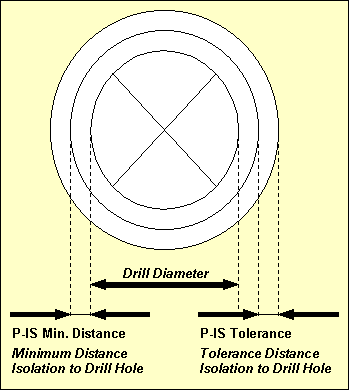
Figure 4-11: CAM Power Layer Isolation
Pin connections into power layers or to power planes placed on power layers are automatically generated with heat trap construction. A heat trap is constructed with four 45 degree isolation circle segments placed round the drill hole of the pin, thus preventing from too much heat flow. The heat trap circle diameters are calculated from the drill hole diameters and the plot parameters to be set with the and functions from the menu. The function is used to specify the minimum distance between the edge of the drill hole and the outside of the heat trap circle. The default value for the heat trap minimum distance is 0.4mm. The function is used to specify the outward tolerance of the heat trap. The default value for the heat trap tolerance is 0.5mm. The heat trap circle diameters are calculated analogously to the isolation circles (see above).
With Gerber photoplot, the CAM Processor checks if there is a thermal aperture available with a diameter matching the calculated tolerance range, which can be used to flash the heat trap. Otherwise, the heat trap is drawn using the smallest round aperture valid for line strokes.
Use the following commands to set the power layer border width to 0.3mm, the power plane isolation width to 0.25mm, the minimum pin isolation width to 0.35mm with a tolerance of 0.4mm (i.e., maximum pin isolation width 0.75mm) and the heat trap distance to 0.35mm with 0.45 tolerance (i.e. maximum heat trap distance 0.8mm):
| Plot Parameters |
| Power Layer Border |
| Power Layer Border Width ( 2.10mm) ? | 0.3 |
| Power Layer Isol. |
| Power Layer Isolation Width ( 0.30mm) ? | 0.25 |
| P-IS Min. Distance |
| Min. Distance Isolation to Drill Hole ( 0.40mm) ? | 0.35 |
| P-IS Tolerance |
| Tolerance Isolation to Drill Hole ( 0.50mm) ? | 0.4 |
| P-HT Min. Distance |
| Min. Distance Heat Trap to Drill Hole ( 0.40mm) ? | 0.35 |
| P-HT Tolerance |
| Tolerance Heat Trap to Drill Hole ( 0.50mm) ? | 0.45 |
The function from the menu is used to produce pen plots in HP-GL (Hewlett-Packard Graphics Language) format.
The function is used to define the pen width for generating HP-GL output data. Structures smaller than the plotter pen width cannot be drawn without overdraw errors. The default plotter pen width is 0.3mm. Pen width value specifications can range from 0.01mm to 10.0mm.
The
function is used to control the pen plotter speed, i.e., the speed at which the pen can be moved by the HP-GL plotter. The system accepts either
S input for maximum speed or non-negative integer plotter speed values in cm/s units. The default plotter speed corresponds with
S (maximum speed). The maximum speed value specification is 99cm/s.
The HP-GL coordinates are written in plotter units where 40.2 plotter units are 1 millimeter. Some HP-GL "compatible" plotters are based on 40 plotter units per millimeter. The function can be used to specify a scale factor for producing true to scale output with non-default plotter units. The default plot scale value is 1.0 for true to scale output. Plot scale specifications can range from 0.1 to 100.0.
The function provides the options and . causes the system to refrain from filling the plot structures, i.e., only outlines are drawn for filled areas. Switching off the fill mode is most useful for fast control plots. is used to select the default fill mode.
The function is used to produce HP-GL pen plots. The user is prompted for the plot layer and the pen number (1..99), and for the name of the output file (if no default output device was specified with ). Note the option provided with the layer selection menu of the function. This option can be used for writing the plot data of multiple selectable layers to a single output file. With the option a popup menu is provided for selecting and/or deselecting the plot data output layers using the right mouse button. Layer selections with the left mouse button also allow for layer-specific pen number selections (on default pen 1 is used for each layer). The button is used to select all currently visible layers for output, with the pen numbers automatically set to modulo eight of the corresponding layer colors.
Use the following commands to set the plotter pen width to 0.2mm, set the plotter speed to 10cm/s, switch off the fill mode and plot the documentary layer
-
of the currently loaded layout to an HP-GL plot file named
demo_bs2.plt using pen number 1:
| Control Plot |
| Plotter Pen Width |
| Plotter Pen Width ( 0.30mm) ? | 0.2 |
| Plotter Speed |
| Plotter Speed (cm/s,S) ? | 10 |
| Fill Mode HP-GL |
| Fill Mode Off |
| Plot Scale |
| Plot Scale Factor ( 1.00) ? | 0.5 |
| HP-GL Output |
| Document Layer |
| Insertion Plan |
| Side 2 |
| Plotter Pen Number (1..99) ? | 1 |
| Plot File Name ? | demo_bs2.plt |
After successfully generating the HP-GL plot file, the CAM Processor issues a message where is the number of overdraw errors. Overdraw errors are highlighted on the layout.
A
PG HPGL command is added to the end of HPGL output files to force a page eject and to prevent from subsequent plots being plotted onto the same sheet. The
option must be used for plotting multiple layers onto the same sheet.
The
function is used to produce HP Laser plots in PCL (Printer Command Language) format. HP Laser plots are automatically scaled to A4 paper size, i.e., neither plot scaling factor nor pen width settings have effect. Use the following commands to generate an HP Laser plot for documentary layer
-
of the currently loaded layout, and direct the output to
lpt1 (e.g., for interfacing an appropriate DOS-connected laser writer device):
| Control Plot |
| HP Laser Output |
| Document Layer |
| Insertion Plan |
| Side 1 |
| Plot File Name ? | lpt1 |
Note the menu item provided with the layer selection menu of the function. This option can be used for writing the plot data of multiple selectable layers to a single output file. With the option a popup menu is provided for selecting and/or deselecting the plot data output layers using the left or right mouse button. The button is used to select all currently visible layers for output.
The CAM Processor issues a message after successfully generating the PCL plot. The scale information in the status message indicates any non-default scaling factor being used for automatic plot to sheet size scaling.
Binary copy mode is required for transferring PCL plot data to the desired output device. I.e., the
/b option must be used when sending PCL files from hard disk to laser printer with the DOS COPY command as in
> copy pclplot lpt1 /b
with
pclplot being the name of the previously written PCL plot file and
lpt1 designating the output device.
The
function from the
menu is used to produce output in Postscript format. Use the following commands to generate a Postscript output file named
demo_l1.ps for signal layer 1 of the currently loaded layout with the standard line width set to 0.25mm and the scaling factor set to 0.75:
| Control Plot |
| Plotter Pen Width |
| Plotter Pen Width ( 0.20mm) ? | 0.25 |
| Plot Scale |
| Plot Scale Factor (0.50) ? | 0.75 |
| Postscript Output |
| Layer 1 |
| Plot File Name ? | demo_l1.ps |
Note the option provided with the layer selection menu of the function. This option can be used for writing the plot data of multiple selectable layers to a single output file. With the option a popup menu is provided for selecting and/or deselecting the plot data output layers using the left or right mouse button. The button is used to select all currently visible layers for output.
The CAM Processor issues a message after successfully generating the Postscript output.
A generic print/plot output function is implemented with the Windows versions of the BAE PC software. I.e., any print/plot output feature supported by the current Windows operating system configuration is also supported with the CAM Processor of the BAE Windows software.
Use the following commands to activate the Windows print/plot menu:
| Control Plot |
| Generic Output |
Note the option provided with the layer selection menu of the function. This option can be used for writing the plot data of multiple selectable layers to a single output file. With the option, a popup menu is provided for selecting and/or deselecting the plot data output layers using the right mouse button. Layer selections with the left mouse button also allow for layer-specific color selections for color plots by assigning pen numbers which correspond with indices to the current color table. The button is used to select all currently visible layers for output, with the color table indices automatically set to modulo-8 layer color numbers.
The Windows printer dialog specifications for the number of copies, page sorting mode and page range are considered by the function.
The option from the Windows printer dialog of the function plots all elements of the currently loaded database class. This allows for the output of, e.g., all layouts of a project. All layouts are plotted according to layout-specific plot parameter settings such as plot rotation modes.
The option from the Windows printer dialog allows for the selection of the print area for generic outputs.
The generic output is automatically scaled to the print page format selected through the Windows printer setup if the size of the element to be plotted exceeds the paper size. The page aspect ratio is maintained when automatic plot scaling is applied. The status message of the function provides information to indicate any non-default scaling factor being used for automatic plot to sheet size scaling.
The function from the menu can be used under Windows for plotting a bitmap of the currently loaded element into the clipboard ready to be imported (e.g., with ) to other Windows applications capable of processing bitmaps. The whole element is plotted on default. The option can be used to restrict the output to a mouse-selectable rectangle. The plot dialog box also allows for bitmap size specifications and plot rotation mirror mode selections.
A black on white plot is generated for single output layer selections. With plot output, the selected layers are plotted with their currently assigned colors (and mixed color display) on black background.
Aperture tables are required for Gerber photoplot outputs. The
menu of the
CAM Processor provides functions for the definition and administration of Gerber aperture tables. Aperture tables are stored to the
cam.dat system file in the BAE programs directory. When installing new BAE software versions you should take care not to overwrite
cam.dat (either use update install mode or make a backup of the
cam.dat system file before installing the BAE software; see the
Bartels AutoEngineer® Installation Guide for more details).
It is important to make the Gerber aperture tables as efficient as possible to minimize the Gerber photoplot data. The reason for this is that an unnecessarily large Gerber file takes up more media space, takes longer to transfer by modem, and takes longer to copy. If the plot is produced by a vector plotter it will also take longer to produce, and cost more. To make the Gerber data more efficient it is important to take into consideration the way the photoplotter plots pads and tracking. The photoplotter has two drawing modes, called line draw and flash. A flash is one single flash of light of a size specified with the aperture, which produces an image of the same size on the plot film. For areas that match apertures, a flash code containing only one set of output coordinates is used. For areas that don't match apertures efficient drawing techniques are used where possible, generating few coordinates but with some shapes and sizes more coordinates are needed. With careful design of pads and appropriate Gerber apertures selected very much smaller Gerber data files can be generated making them quicker to copy, cheaper to send by modem, and require less media space.
For orthogonally placed square and rectangular pads that have a matching aperture a flash is used. For rectangular pads that have sides along the X and Y axis and the smaller side matching a square aperture, that aperture is used to draw the pad. For rectangular pads (and square pads that don't have an aperture that matches) that have sides along the X and Y axis and a square aperture exists that is bigger than half the shortest side, that aperture is used to draw the pad with two strokes. For rectangular pads that don't have their sides along the X and Y axis, area fill techniques are used. For round pads that have an aperture that matches a flash is used. For round pads where no aperture matches, area fill techniques are used where line fill will use the nearest smaller aperture to draw the pad by moving in a circular path. Finger pads (rectangles with semi-circles at two opposite sides) are plotted like trace segments, i.e., line draws with matching circular apertures are applied on finger pads.
Area fill techniques are applied for pads which don't meet the above specification. A draw is used for trace widths matching a round aperture. For trace widths that don't match an aperture, overlapping lines are drawn using the next smallest round aperture. Irregularly shaped areas are always generated using fill techniques.
The , and functions from the menu are used to load, save and delete Gerber aperture tables. The function provides a list of all of the available Gerber aperture tables. The function issues an error message such as
Gerber aperture table overflow!
when trying to load aperture tables containing more than 900 apertures. Such errors indicate a corrupt
cam.dat file since the
Bartels AutoEngineer it is not capable of creating and/or processing aperture tables with more than 900 apertures. When starting the
CAM Processor, the aperture table named
standard is automatically loaded.
Table 4-4 lists all apertures defined with the
standard aperture table.
Table 4-4: Gerber Aperture Table "standard"
| D-Code | Aperture Type | Aperture Size | Drawing Mode | |
|---|---|---|---|---|
| [mil] | [mm] | |||
| D10 | round | 7.87 | 0.200 | ALL |
| D11 | round | 8.27 | 0.210 | ALL |
| D12 | round | 9.84 | 0.250 | ALL |
| D13 | round | 11.81 | 0.300 | ALL |
| D14 | round | 15.75 | 0.400 | ALL |
| D15 | round | 19.69 | 0.500 | ALL |
| D16 | round | 23.62 | 0.600 | ALL |
| D17 | round | 27.56 | 0.700 | ALL |
| D18 | round | 31.50 | 0.800 | ALL |
| D19 | round | 35.43 | 0.900 | ALL |
| D20 | round | 39.37 | 1.000 | ALL |
| D21 | round | 43.31 | 1.100 | ALL |
| D22 | round | 47.24 | 1.200 | ALL |
| D23 | round | 51.18 | 1.300 | ALL |
| D24 | round | 59.06 | 1.500 | ALL |
| D25 | round | 62.99 | 1.600 | ALL |
| D26 | round | 66.93 | 1.700 | ALL |
| D27 | round | 78.74 | 2.000 | ALL |
| D28 | round | 90.55 | 2.300 | ALL |
| D29 | round | 98.43 | 2.500 | ALL |
| D30 | round | 102.36 | 2.600 | ALL |
| D31 | round | 110.24 | 2.800 | ALL |
| D32 | round | 118.11 | 3.000 | ALL |
| D33 | round | 129.92 | 3.300 | ALL |
| D34 | round | 137.80 | 3.500 | ALL |
| D35 | round | 149.61 | 3.800 | ALL |
| D36 | round | 157.48 | 4.000 | ALL |
| D37 | round | 169.29 | 4.300 | ALL |
| D38 | square | 15.75 | 0.400 | ALL |
| D39 | square | 19.69 | 0.500 | ALL |
| D40 | square | 23.62 | 0.600 | ALL |
| D41 | square | 29.53 | 0.750 | ALL |
| D42 | square | 31.50 | 0.800 | ALL |
| D43 | square | 39.37 | 1.000 | ALL |
| D44 | square | 43.31 | 1.100 | ALL |
| D45 | square | 47.24 | 1.200 | ALL |
| D46 | square | 51.18 | 1.300 | ALL |
| D47 | square | 59.06 | 1.500 | ALL |
| D48 | square | 62.99 | 1.600 | ALL |
| D49 | square | 78.74 | 2.000 | ALL |
| D50 | square | 86.61 | 2.200 | ALL |
| D51 | square | 118.11 | 3.000 | ALL |
| D52 | square | 129.92 | 3.300 | ALL |
| D53 | thermal | 70.87 | 1.800 | ALL |
| D54 | thermal | 86.61 | 2.200 | ALL |
| D55 | thermal | 98.43 | 2.500 | ALL |
The
function is used to edit entries in the currently loaded aperture table. After activating the
function, the system provides a listing of the currently loaded aperture table where
+ and
- keys can be used to scroll forward and/or backward in this list, and the return key
![]() can be used to return to the
CAM Processor main menu. For changing a certain aperture table entry the appropriate aperture table index must be entered. Empty string inputs (i.e., pressing the return key
can be used to return to the
CAM Processor main menu. For changing a certain aperture table entry the appropriate aperture table index must be entered. Empty string inputs (i.e., pressing the return key
![]() ) on subsequent aperture specification prompts causes the system to accept predefined values. The first prompt is used to specify the aperture type and/or shape, where
) on subsequent aperture specification prompts causes the system to accept predefined values. The first prompt is used to specify the aperture type and/or shape, where
r defines a round aperture,
q defines a square-shaped aperture,
a defines a rectangular aperture,
t defines a thermal aperture and
s defines a special aperture. Note that special apertures are not utilized by the
CAM Processor (special aperture types are reserved for future functions). A dash string input
(-) to the aperture type prompt causes the system to delete the selected entry from the aperture table. After specifying the aperture type, the system prompts for the diameter and/or the edge length(s) of the aperture. The aperture size can be input in either mm or inch units and is automatically be converted to mm units in the aperture table. The next prompt is used for specifying the aperture drawing mode, where
f (Flash) defines the aperture to be used for flashes only,
l (Line) defines the aperture to be used for line drawing only and
a (All) defines for either flash or line drawing whatever is appropriate. The last aperture definition prompt is used for specifying the Gerber D-Code number of the aperture, where valid D-Codes range from 10 to 999. It is strongly recommended to ensure unique D-Codes in each Gerber aperture table to prevent the
CAM Processor from random use of multiple defined D-Codes.
Note that square-shaped and rectangular aperture can be used for flashing orthogonal placed pads only. It is also strongly recommended to check whether the PCB manufacturer supports rectangular apertures.
Use the following commands to define a round line aperture with 0.3mm diameter and D-Code 10 at aperture table index 1:
| Gerber Photoplot |
| Edit Aperture Table |
| Gerber Aperture Table Index (1..900,+,-) ? | 1 |
| Aperture (R)ound/S(Q)uare/(T)hermal/(S)pecial/(A)rea/(-) ? | r |
| Aperture Diameter/Side Length (0.127mm) ? | 0.3 |
| Drawing Mode (A)ll/(F)lash/(L)ine ? | l |
| Gerber D-Code Number (10-999) ? | 10 |
| Gerber Aperture Table Index (1..900,+,-) ? | |
An empty string input (i.e., pressing the return key
![]() ) to the aperture table index prompt causes the system to return to the
CAM Processor main menu. The
function is used to generate an ASCII listing of the currently loaded aperture table. The
function is used to save the currently loaded aperture table with a selectable name in the
) to the aperture table index prompt causes the system to return to the
CAM Processor main menu. The
function is used to generate an ASCII listing of the currently loaded aperture table. The
function is used to save the currently loaded aperture table with a selectable name in the
cam.dat system file.
The function is used to specify the Gerber output format. The option produces 1/1000 inch integer coordinates. The option produces 1/10000 inch integer coordinates. is selected on default.
The and options are provided for optionally generating optimized Gerber output with redundant D01 ("light off") plotter control commands eliminated, thus significantly reducing the amount of Gerber output plot data. However, it is strongly recommended to check whether the PCB manufacturer supports optimized Gerber format.
The function is used to define the standard line width for Gerber output. The standard line width is used for drawing graphic lines and texts. A round aperture for line drawing is required for the standard line width; otherwise the CAM Processor issues an error message such as
Cannot realize the default line width!
when trying to generate Gerber photoplots. The standard line width is set to 0.3mm on default.
The function is used to select the technique for filling irregularly shaped areas (i.e., those areas not matching any aperture for flash or line stroke).
Option is used to select the single-aperture line fill technique which uses the smallest line aperture for filling irregularly shaped areas with line strokes.
Option selects the multi-aperture fill technique, which is the default. The algorithm used by the multi-aperture fill technique fills areas from the area outline using the smallest aperture and proceeds using larger apertures when moving to the inner of the area. This results in distinct reduction of Gerber data output when using appropriate Gerber aperture tables for layouts with many irregularly shaped areas.
With the mode option activated, non-flashable structures are stored with their outline contour, and will be filled by the photo plotter. This feature significantly reduces the amount of Gerber plot data and also eliminates plot overdraw errors. However, it is strongly recommended to check with the PCB manufacturer whether the photo plotter is capable of processing G36/G37 Gerber data.
The function is used to enable Gerber I/J arc commands (option ) instead of applying arc interpolation (default option ). Gerber arc commands should always be used if the photo plotter is capable of interpreting these commands since this feature results in considerably reduced amounts of Gerber output data.
The function can be used for optionally generating RS-274-X format Gerber output (Extended Gerber with Embedded Apertures). provides the options , and .
is the default mode for generating standard Gerber data without embedded apertures. With Extended Gerber mode selected, the Gerber aperture table and the Gerber format selection are included (i.e., embedded) with the Gerber output plot file. The Gerber aperture table to be used and/or embedded can either be the currently active aperture table (option ) or a dynamically (i.e., automatically) generated aperture table (option ). Note that the dynamic aperture table is generated for the whole layout data rather than for the currently plotted layer only. With Extended Gerber the aperture table is automatically transferred to the PCB manufacturer as an integral part of the plot file, and no extra aperture table information file must be generated and/or transferred. With the option, there is also no need for defining and/or activating an aperture table before starting the Gerber plot output.
It is strongly recommended to check whether the PCB manufacturer supports Extended Gerber format before applying this feature. It is also recommended to refrain from using the option with multi-aperture fill mode activated since automatically generated aperture tables usually are not appropriate for multi-aperture filling.
The function is used to start Gerber photoplot output for a selectable plot layer. Note the option provided with the layer selection menu of the function. This option can be used for writing the photoplot data of multiple selectable layers to a single output file. With the option a popup menu is provided for selecting and/or deselecting the plot data output layers using the left or right mouse button. The button is used to select all currently visible layers for output.
Use the following commands to generate a Gerber photoplot output file named
demo_l2.ger for signal layer 2 of the currently loaded layout, using the currently loaded Gerber aperture table with standard line width 0.254mm, Gerber format 2.4 and line fill mode:
| Gerber Photoplot |
| Default Line Width |
| Gerber Default Line Width ( 0.30mm) ? | 0.254 |
| Gerber Format |
| Gerber 2.4 Format |
| Gerber Fill Mode |
| Line Fill |
| Gerber Output |
| Layer 2 |
| Plot File Name ? | demo_l2.ger |
The following report is issued by the function after successfully generating the Gerber plot file:
Number of Flash Structures .............: <f> Number of Rectangle Drawn Areas ........: <r> Number of Circle Drawn Areas ...........: <c> Number of Multi Aperture Areas .........: <m> Number of Line Filled Areas ............: <l> Number of Heat Traps ...................: <w> Number of Overdraw Errors ..............: <e>
<f> is the number of structures which have been generated using a flash aperture.
<r> is the number of rectangular-shaped areas which have been generated using a square line aperture.
<c> is the number of circles which have been generated with a circular draw of a smaller round line aperture.
<m> is the number of structures which have been generated using multi-aperture fill techniques.
<l> is the number of structures which have been generated using line fill techniques.
<w> is the number of heat traps which have been drawn using the smallest round line aperture.
<e> is the number of structures which could not be generated within the specified plot tolerance using the smallest aperture.
It is strongly recommended to refrain from passing Gerber photoplot output with overdraw errors to the PCB manufacturer since there might be PCBs produced containing short-circuits.
The CAM View module of the Bartels AutoEngineer can be used to perform visual checks and panelization on the generated Gerber data (see chapter 4.8 for a description of the CAM View module).
The menu provides functions for generating drilling data output in Excellon II and/or Sieb&Meier format. The CAM View module can be used to perform visual checks, coordinates sorting and panelization on the generated drilling data (see chapter 4.8 for more details).
The function from the menu is used for generating drilling data in Excellon II format. With Excellon II format, both the drilling data and the drilling tool table are stored to a single output file.
The function can be used to specify a default name for the Excellon output file. The function is used to define the tolerance for selecting drill tools. The default value for the drill tolerance is 0.10mm.
With the function, the drill class must be specified, thus providing a feature for selecting different types of drill holes for output such as plated and/or non-plated drill holes or drill holes defined on blind and buried vias (whichever is assigned with the selected drill class). A dash string input ("-") to the drilling class prompt selects those drill holes for output which are not assigned to any specific drill class.
The and functions from the menu are used for generating drilling data and drilling tool table output in Sieb&Meier format.
The and functions can be used to specify default names for the Sieb&Meier output files. The function is used to define the tolerance for selecting drill tools. The default value for the drill tolerance is 0.10mm.
The tool table file to be generated with the function provides a listing of all drill diameters used for output, with a drill tool number assigned to each drill diameter. Up to 99 different drill diameters can be processed. The output function aborts with the error message if more than 99 different drill diameters are defined on the current layout.
With Sieb&Meier format, each drill hole is listed in a single line providing drill coordinates in 1/100mm integer units. With each drill diameter change, the appropriate drill tool number is appended to the end of the corresponding drill data line, thus representing a command for selecting and/or changing the drill tool.
With the function, the drill class must be specified, thus providing a feature for selecting different types of drill holes for output such as plated and/or non-plated drill holes or drill holes defined on blind and buried vias (whichever is assigned with the selected drill class).
Use the following commands to set the drill tool tolerance to 0.05mm, generate the drill data output file
demo.drl for the drill class
Z which is used on the currently loaded layout, and write the drill tool table file
demo.tol:
| Drilling+Insertion |
| Tool Range |
| Drill Tolerance Range ( 0.1mm) ? | 0.05 |
| Drill Output |
| New Drilling Class (-,A..Z) (-) ? | Z |
| Drill Data File Name ? | demo.drl |
| Tool Table Output |
| Tool Table File Name ? | demo.tol |
A dash string input ("-") to the drilling class prompt selects those drill holes for output which are not assigned to any specific drill class. The CAM Processor issues a message after successfully generating the drill data output.
With the commands above, a drill tool table file named
demo.tol with the following contents is generated:
/* Drill(Number) Drill Diameter(mm) */ 1 0.50 2 0.80 3 0.90 4 1.00 5 1.30 6 3.00
With the commands above, a drill data file named
demo.drl with the following contents is generated:
% X1016Y762T6 X1016Y6350 M30
The menu provides functions for generating output data for automatic insertion equipment and pick and place machines. The CAM Processor produces insertion data in generic format where all texts placed on a selectable insertion data layer are listed with coordinates (in 1/100mm integer units) and rotation angles (in degree units).
It is recommended to define a special documentary layer for insertion data output and to place the
$ text string on that layer on each part symbol, thus representing the part name placed at the pick point for the automatic insertion equipment (e.g., at pin 1 for parts with drilled pins or at the part pin gravity point for SMDs). The insertion data documentary layer should be defined with the
PHYSICAL text attribute to fix the positions of insertion data text strings. See also
chapter 7.2 of this manual for a description of the
LAYDOCLAYER command of the
bsetup utility program.
The function from the menu is used to generate insertion data output. After activating the function, the user is prompted for the insertion data layer and the insertion data output file name. Note the option provided with the layer selection menu of the function. This option can be used for writing the insertion data of multiple selectable layers to a single output file. With the option, a popup menu is provided for selecting and/or deselecting insertion data output layers using the left or right mouse button. The button is used to select all currently visible layers for output.
Use the following commands to generate insertion data output for the solder side of the currently loaded layout (select documentary layer
-
for output, and direct the output data to a file named
demo.id1):
| Drilling+Insertion |
| Insertion Output |
| Document Layer |
| Insertion Plan |
| Side 1 |
| Insertion Data File Name ? | demo.id1 |
The CAM Processor issues the
Insertion data write done!
message after successfully generating the insertion data output, and the insertion data file
demo.id1 should have the following contents:
/* Name X(mm) Y(mm) Angle(Degrees) */ C100 4635 3651 0 C101 3619 3651 0 R104 984 5016 270
The CAM View module provides features for displaying Gerber data ("Gerber View"), Sieb&Meier and/or Excellon drilling data and Excellon milling data in order to check CAM data validity and to estimate the efficiency of tool usage. CAM View features multiple input, selective data set movement and sorted output with variable offsets, optional mirroring and adjustable aperture tables, thus supporting panelization. CAM View also provides a powerful function for translating Gerber data to BAE layout design data, i.e., with CAM View the user is able to import Gerber data produced by foreign PCB layout systems.
It is recommended to start the Bartels AutoEngineer from the directory where the design files should be generated since this considerably simplifies job file access. If you intend to process the examples provided with this manual it is recommended to move to the BAE examples directory installed with the BAE software. The CAM View module can be called from the Bartels AutoEngineer main shell. Start the BAE shell by typing the following command to the operating system prompt:
> bae
Move the menu cursor to the CAM View menu item and confirm this choice by pressing the left mouse button:
| CAM View |
The CAM View program module is loaded and the CAM View menu is activated. If this fails to happen then check your BAE software installation (see the Bartels AutoEngineer® Installation Guide for details on how to perform a correct installation).
The CAM View standard/sidemenu user interface provides a menu area on the right side, consisting of the main menu on top and the currently active menu below that main menu. After entering CAM View, the menu is active and the menu cursor points to the function.
The Windows and Motif versions of the
CAM View module can optionally be operated with a pull-down menu user interface providing a horizontally arranged main menu bar on top. The
WINMENUMODE command of the
bsetup utility program is used to switch between
SIDEMENU and
PULLDOWN Windows/Motif menu configurations. See
chapter 7.2 for more details.
The following main menu is always available whilst processing CAM data with CAM View:
| Display |
| Files |
| Parameter |
| Utilities |
The or menu can either be activated by selecting the corresponding main menu item or by pressing the middle mouse button. The or menu provides useful functions for changing display options such as zoom window, zoom scale, input and display grid, color settings, drawing mode, coordinate display mode, etc.
The menu provides functions for loading, moving and writing Gerber, drilling or milling data sets, for generating layouts from Gerber data and for deleting the currently loaded CAM data from main memory.
The menu provides functions for setting input offsets and mirror modes for subsequent data load processes, defining the via D-Code for generating layouts from Gerber data, selecting the Gerber format, the circle mode, the coordinate format, and activating and/or deactivating Extended Gerber format or Gerber optimization when loading and/or writing Gerber data.
The menu provides functions for exiting BAE, returning to the BAE main shell, sorting drill data, reporting aperture usage and listing DDB file contents.
The BAE software comes with User Language programs for activating a modified CAM View user interface with many additional functions (startups, toolbars, menu assignments, key bindings, etc.). The bae_st User Language program is automatically started when entering the CAM View module. bae_st calls the uifsetup User Language program which activates predefined CAM View menu assignments and key bindings. Menu assignments and key bindings can be changed by modifiying and re-compiling the uifsetup source code. The hlpkeys User Language program is used to list the current key bindings. With the predefined menu assignments of uifsetup activated, hlpkeys can be called from the function of the menu. Menu assignments and key bindings can be listed with the uifdump User Language program. The uifreset User Language program can be used to reset all currently defined menu assignments and key bindings. uifsetup, uifdump and uifreset can also be called from the menu of the keyprog User Language program which provides additional facilities for online key programming and User Language program help info management.
The Windows and Motif pulldown menu user interfaces of the CAM View module provide facilities for cascading submenu definitions. I.e., submenus can be attached to other menu items. The uifsetup User Language program configures cascading submenus for the pulldown menu interfaces of the Windows/Motif CAM View modules. This allows for easy submenu function location (and activation) without having to activate (and probably cancel) submenus. The function repeat facility provided through the right mouse button supports cascading menus to simplify repeated submenu function calls.
The following Windows/Motif parameter setup dialogs are implemented for the CAM View module:
The uifsetup User Language program replaces the parameter setup functions of the Windows and Motif pulldown menus with the above menu functions for activating the corresponding parameter setup dialogs.
When using pulldown menus under Windows and Motif, the uifsetup User Language program configures the following modified CAM View main menu with a series of additional functions and features:
| File |
| Edit |
| View |
| Settings |
| Utilities |
| Help |
The Bartels User Language Interpreter is integrated to the CAM View module, i.e., User Language programs can be called from CAM View. It is possible to implement any user-specific CAM View function required such as status display, parameter setup, reports and test functions, customer-specific batch procedures, etc.
CAM View provides both explicit and implicit
User Language program call facilities.
User Language programs can be started with explicit program name specification using the
function from the
menu (empty string or question-mark
(?) input to the program name query activates a
User Language program selection menu).
User Language programs can also be called by simply pressing special keys of the keyboard. This method of implicit User Language call is supported at any time unless another interactive keyboard input request is currently pending. The name of the User Language program to be called is automatically derived from the pressed key, i.e. pressing a standard and/or function key triggers the activation of a User Language program with a corresponding name such as cv_1 for digit key 1, cv_r for standard key r, cv_# for standard key #, cv_f1 for function key F1, cv_f2 for function key F2, etc.
The CAM View User Language Interpreter environment also features event-driven User Language program calls, where User Language programs with predefined names are automatically started at certain events and/or operations such as cv_st at CAM View module startup, cv_tool when selecting a toolbar item and cv_zoom when changing the zoom factor. The module startup User Language program call method is most useful for automatic system parameter setup as well as for key programming and menu assignments. The toolbar selection event must be used to start User Language programs which are linked to toolbar elements. The zoom event can be used to apply an update request to a design view management feature.
Bartels User Language also provides system functions for performing key programming, changing menu assignments and defining toolbars. These powerful features can be applied for user interface modifications. Please note that a large number of additional functions included with the CAM View menu are implemented through the User Language programs supplied with the BAE software.
See the Bartels User Language Programmer's Guide for a detailed description of the Bartels User Language (chapter 4.2 lists all User Language programs provided with the BAE software).
The , , , , , , and functions from the menu are used to set global parameters for loading and/or writing Gerber and/or drilling/milling data sets.
The input offset is added to the input coordinates when loading CAM data. Different input offsets can be specified to load the same layout at different positions, and, subsequently, the whole data can be written to Gerber and/or drill data output files to support panelization. CAM View can hold Gerber data from different layers and drill data in main memory at the same time. I.e., only one input offset specification is required for each panel element. The function from the menu can be used to delete previously loaded CAM data from memory before loading new CAM data for panelization.
The function from the menu is used to specify the Gerber format for loading and/or writing Gerber data. The default option selects 1/1000 inch integer units. Option selects 1/10000 inch integer units. With option the user is prompted for the length of one plotter unit, thus supporting arbitrary Gerber format specifications.
The function from the menu is used to select the mode of processing arc segments when loading Gerber data. With the default option, arbitrary arc definitions can be loaded without modification. This is valid for the Gerber data generated by the BAE CAM Processor and most of the known foreign systems. Some foreign systems can only generate arcs of up to 90 degrees where the length of the arc center point vector is also specified. In this case, the option of the function is only furnished for correct Gerber data processing.
The function from the menu is used for optionally mirroring the input data set(s) to be subsequently loaded. The mirror modes provided with the function are (default), , and , respectively. Note that input data mirroring is always done before any input data offset specification applies.
The function from the menu is used to specify whether Gerber coordinate specifications are to be interpreted with trailing and/or leading zeros suppressed. On default, the mode for expecting trailing zeros and suppressing leading zeros is used. The mode for suppressing trailing zeros and expecting leading zeros is only valid with Gerber Format 2.3 and Gerber Format 2.4, i.e., any other Gerber format specification defaults to the mode.
The function can be used for optionally generating RS-274-X format Gerber output (Extended Gerber with Embedded Apertures). On input, RS-274-X Gerber format is automatically recognized by CAM View.
The function can be used for optionally generating optimized Gerber output with redundant D01 ("light off") plotter control commands eliminated, thus significantly reducing the amount of Gerber output plot data. On input, optimized Gerber data is automatically recognized by CAM View.
The function can be used to select the coordinate input mode for Gerber and/or Excellon data load operations. With the option, input coordinates are assumed to be absolute, whilst with option , input coordinates are assumed to be relative and/or incremental.
For correctly loading and displaying Gerber data the same aperture table is required as was used when generating the Gerber plot. Both the
CAM Processor and the
CAM View module provide functions for the definition and administration of Gerber aperture tables. Aperture tables are stored to the
cam.dat system file in the BAE programs directory. The aperture table named
standard is loaded automatically when starting
CAM View. The
function from the
menu can be used to load any other aperture table available in
cam.dat. The
function from the
menu can be used to change aperture definitions in the currently loaded aperture table. The
and
functions can also be used after loading Gerber data, which would cause a Gerber data display update according to changed aperture definitions. The
function from the
menu can be used to save the currently loaded aperture table with a selectable name to the
cam.dat system file.
Use the following commands to define a round line aperture with 0.3mm diameter and D-Code 10 at aperture table index 1:
| Edit Aperture Table |
| Gerber Aperture Table Index (1..900,+,-) ? | 1 |
| Aperture (R)ound/S(Q)uare/(T)hermal/(S)pecial/(A)rea/(-) ? | r |
| Aperture Diameter/Side Length (0.127mm) ? | 0.3 |
| Drawing Mode (A)ll/(F)lash/(L)ine ? | l |
| Gerber D-Code Number (10-999) ? | 10 |
| Gerber Aperture Table Index (1..900,+,-) ? | |
The function from the menu is used to load Gerber photoplot data files. The user is prompted for the Gerber plot file name after specifying layers for line drawn structures and flashed structures, respectively. The line draw and flash layer assignment is required by the features for decoding Gerber data to BAE layout data (see below). Gerber input layer assignments can also be utilized for panelization where Gerber data from different layers must be written to separate data files.
Layer assignments can also be used for comparing different Gerber file versions of the same layout. When loading different Gerber files versions to different layers, then the common structures are displayed with mixed colors resulting from the colors assigned to the input layers (if the option is selected with the function from the menu).
Use the following commands to select Gerber format 2.4, and load the Gerber plot file
demo_l2.ger which has been generated in
chapter 4.7.11 (select layer 2 for both the line drawn and the flashed structures):
| Settings |
| Gerber Format |
| Gerber 2.4 Format |
| File |
| Load Gerber Data |
| Layer 2 |
| Layer 2 |
| Plot File Name ? | demo_l2.ger |
Use the following commands to repeat the Gerber load from above with an input offset of 3.2 inch in X direction:
| Settings |
| Input Offset |
| X-Offset (0.000 mm) ? | 3.2" |
| Y-Offset (0.000 mm) ? | 0 |
| File |
| Load Gerber Data |
| Layer 2 |
| Layer 2 |
| Plot File Name ? | demo_l2.ger |
The menu provides functions for changing general display options such as zoom window, zoom scale, display grid, color settings, etc.
The function is used to select the mode for displaying Gerber data. The default option displays structures as pure areas. Option also displays aperture outlines, thus providing most information about how areas have been filled.
The function is used to select the mode of color assignment. With default option colors can be assigned to D-Codes and aperture drawing modes. With option colors can be assigned to layers.
The
function operates according to the current
. With
, the
function provides a layer selection menu. With
, the
function prompts for a D-Code number and a drawing mode, where
f (Flash) selects flashed structures,
l (Line) selects line drawn structures and
b (Border) selects drawing area outlines. The default D-Code color setup is light gray for flashed structures, gray for line drawn structures and red for border lines.
Use the following commands to select the yellow color for the line drawn structures which have been generated using D-Code 10:
| View |
| Color Assignment |
| D-Code Assignment |
| Change Colors |
| Gerber D-Code Number (10-999) ? | 10 |
| Mode (f)lash/(l)ine/(b)order ? | l |
| Move to Desired Color,yellow |
Black color assignments can be used to suppress the display of selected elements.
The function from the menu provides a statistical report on what apertures and/or D-Codes are how often used for what kind of structures.
Use the following commands to activate the function:
| Utilities |
| Report |
After activating the command above the following listing should appear in the graphic workarea:
D10 0.30 mm Rnd. :
Lines : 58
D11 0.25 mm Rnd. :
Lines : 454
D16 1.52 mm Rnd. :
Flashed : 64
D18 2.54 mm Rnd. :
Flashed : 16
Lines : 4
D29 1.40 mm Sqr. :
Flashed : 20 ...
Structures reported with a mode are unexposed Gerber coordinates.
The function from the menu can be used for moving previously loaded Gerber data sets. The data to be moved can be selected from a popup menu where available data sets are listed according to the load sequence. Each data set entry of the popup menu displays the layer(s), the offset to origin, the mirror mode and the input data file name. After selecting the desired data set, the user must specify the movement vector by selecting the start and end point of the movement. During these selections, the input grid corresponds with the current display grid settings. Pressing the right mouse button during data set movement activates a context menu with functions for performing absolute and/or relative jumps.
The function from the menu is used to write currently loaded Gerber data of a selectable layer to a named file.
Use the following commands to select Gerber format 2.3, and write the Gerber data currently loaded to layer 2 to a Gerber file named
demo_l2.g25:
| Settings |
| Gerber Format |
| Gerber 2.3 Format |
| File |
| Save Gerber Data |
| Layer 2 |
| Plot File Name ? | demo_l2.g25 |
The function from the menu is used to delete the currently loaded data from memory and to re-initialize the display to prepare for loading other data. Use the following commands to clear the memory:
| File |
| Clear Memory |
The function from the menu is used to load drilling and/or milling data. The function for loading a drill tool table must be applied before loading Sieb&Meier drill data; otherwise the function issues a error. Take care that the tool table corresponds with the drill data to ensure complete and correct drill data management. Note that the function deletes previously loaded drill data from memory.
The function allows for the selection of either Sieb&Meier or Excellon format. Both input units and processing of trailing and/or leading spaces are automatically derived from the input data file. The current Gerber input parameter and/or format specifications are automatically used for input data not providing corresponding format commands. Excellon input Inch unit specifications are processed using the currently selected Gerber format (Gerber Format 2.3, Gerber Format 2.4, etc.).
The function for loading Excellon data features automatic milling data recognition, i.e., Excellon milling data is automatically recognized and/or processed. With Excellon output function the output data type (i.e., either drilling data or milling data) must be specified since each drill class can contain both milling and drilling data.
The drilling and/or milling data sets are loaded and saved with drill class specification, respectively. It is possible to load drilling and/or milling data sets with different drill classes and to generate drilling and/or milling data output with selectable drill classes. With milling data the drill class can be used to differ between plated and non-plated. Drill holes and milling puncture points not assigned to the standard
(-) drill class are indicated with the corresponding drill class letter
(A,
B, ...,
Z).
The function automatically activates the color table entry for the drilling data display. This color table entry is set to white if it is still undefined (i.e., black and/or invisible). This ensures that drilling data load operations can be visually monitored.
Use the following commands to load the Sieb&Meier drill data file
demo.drl to drill class
- using the corresponding drill tool table
demo.tol (see also
chapter 4.7.12, where these files have been generated):
| File |
| Load Tool Table |
| Tool Table File Name ? | demo.tol |
| Load Drill Data |
| Drill Data File Name ? | demo.drl |
| New drill class (-,A..Z) (-) ? | - |
| Sieb & Meier |
Currently loaded drilling and/or milling data can be displayed using the layer color assignment with a non-black color (e.g., white) selected for the drill holes, as in:
| View |
| Color Assignment |
| Layer Assignment |
| Change Colors |
| Drill Holes |
| Move to Desired Color,white |
| Exit |
The function from the menu can be used for moving previously loaded drilling and/or milling data sets. The data to be moved can be selected from a popup menu where available data sets are listed according to the load sequence. Each data set entry of the popup menu displays the layer(s), the offset to origin, the mirror mode and the input data file name. After selecting the desired data set the user must specify the movement vector by selecting the start and end point of the movement. During these selections, the input grid corresponds with the current display grid settings. Pressing the right mouse button during data set movement activates a context menu with functions for performing absolute and/or relative jumps.
The function from the menu is used to write currently loaded drilling and/or milling data to a named file.
Use the following commands to write the currently loaded drilling data in Excellon format with drill class
- to output file
demo.exc:
| File |
| Save Drill Data |
| Drill Data File Name ? | demo.exc |
| New drill class (-,A..Z) (-) ? | - |
| Excellon |
| Drill Data |
The function from the menu is used to activate an algorithm for sorting the currently loaded drill data to minimize the distances between subsequent drill holes. Note that performs separate sorting on each of the currently loaded drilling data sets. Overall sort on multiple drill data sets can be applied by loading all data sets, save them as single data set, clear the memory, reload the single data set and run the function on the reloaded data set. Note also that the complexity of the drill sort algorithm grows quadratically with the number of drillings per tool, thus raising CPU time requirements enormously when working on large layouts and/or panels (>1000 drill holes).
Use the following commands to sort the currently loaded drill data, and write the sorted drill data to a file named
demosort.drl:
| Utilities |
| Sort Drill Data |
| File |
| Save Drill Data |
| Drill Data File Name ? | demosort.drl |
All of the required Gerber data must be loaded to the CAM View module before generating a layout from that Gerber data. When loading Gerber data for layout generation, the line drawn structures should be loaded to their respective layers whilst the flashed structures can be loaded to either signal layers or documentary layers. In most cases it is advisable to load the flashed structures onto documentary layers since flashed structures usually represent pads which, when placed on signal layers, would create redundant copper at the layout pin positions once the corresponding parts are loaded. Pad info retrieved from the flashed structures should rather serve as an aid for placing the parts on the layout. It is a good idea to select a special documentary layer such as for loading flashed structures. Certain documentary Gerber plots such as the can also be loaded to the corresponding BAE documentary layer to support subsequent part placement procedures.
After loading all Gerber data to CAM View, the function from the menu can be used to generate a layout from that Gerber data. With the function first a via D-Code must be specified. Use the function and/or appropriate D-Code color assignments to find out which D-Code is used for vias. Flashed structures generated with the specified via D-Code are translated to via definitions. Automatic via translation is only carried out for the first Gerber data input file to avoid multiple via placement at the same coordinates. The function automatically generates a via padstack using an all layer pad with the size of the selected via aperture and a drill hole with half that aperture size.
After specifying the via D-Code, the function prompts for the file and element name where the layout should be written to. Note that overwrites previously existing layout elements (nevertheless, you can use the Layout Editor group functions to mix different layouts retrieved from Gerber data).
The sequence of the following operations is crucial for the creation of valid layout data.
After successfully running the function from the CAM View menu, you should return to the BAE main menu (use function from the menu) and start the Layout Editor. Within the Layout Editor you should load the layout and place all of the required parts (use the function from the menu). Note that User Language programs can be used for automatic placement instead of interactive placement if placement data ASCII files are available with appropriate formats. After completing the placement the layout should be saved, and then the function from the menu should be used to generate a net list with the same file and element names as were specified when creating the layout. generates a net list from the copper placed on the currently loaded layout. However, works only on DDB file level, i.e., it won't change the currently loaded net list. You should re-load the layout immediately after running (refrain from activating any function which could store the still empty net list currently held in main memory). A connectivity generation is automatically carried out after re-loading the layout, and then the layout is ready for processing by the Bartels AutoEngineer.
NOTE
The software modules described in this chapter are only available in Bartels AutoEngineer IC Design.
This chapter describes how to use the Chip Editor (IC Mask Editor), Cell Placer, and Cell Router program modules for the physical design of IC and/or ASIC mask layouts. The GDS View and CIF View program modules for importing and/or checking cell libraries and/or IC mask data in GDS and CIF format are also introduced. Unfortunately, we can't provide real design examples in this chapter because the IC manufacturing process parameters and the cell libraries of logical primitives are usually provided by the manufacturer. Although your manufacturer is unlikely to charge anything for the provision of such data in a format suitable for import into the Bartels AutoEngineer (such as GDS), the publication of this data is usually strictly prohibited by a non disclosure agreement (NDA).
| 5.1 | General |
| 5.1.1 | Components and Features |
| 5.1.2 | IC Design System Startup |
| 5.1.3 | Chip Editor Main Menu |
| 5.1.4 | Chip Editor User Interface |
| 5.1.5 | Chip Editor System Features |
| 5.2 | IC Cell Library |
| 5.2.1 | IC Pin Definitions |
| 5.2.2 | IC Cell Definitions |
| 5.3 | IC Mask Layout |
| 5.3.1 | Creating and Editing Chip Layouts |
| 5.3.2 | Cell Makros, Placement |
| 5.3.3 | Text and Graphic |
| 5.3.4 | Traces, Routing |
| 5.4 | Cell Placer |
| 5.4.1 | Cell Placer Startup |
| 5.4.2 | Cell Placer Main Menu |
| 5.4.3 | Cell Placer System Features |
| 5.4.4 | Cell Placer Options |
| 5.4.5 | Cell Placer Control |
| 5.4.6 | Cell Placer Functions |
| 5.5 | Cell Router |
| 5.5.1 | Cell Router Startup |
| 5.5.2 | Cell Router Main Menu |
| 5.5.3 | Cell Router System Features |
| 5.5.4 | Cell Router Options |
| 5.5.5 | Cell Router Control |
| 5.5.6 | Cell Router Strategy |
| 5.5.7 | Cell Router Functions |
| 5.6 | IC Design Data Import and Export |
| 5.6.1 | GDS Data Import and Output |
| 5.6.2 | CIF Data Import and Output |
| Tables |
| 5-1 | Cell Router Strategy Parameters |
The Bartels AutoEngineer IC Design system essentially consists of an interactive Chip Editor (IC Mask Editor) with integrated cell/macro symbol editor and comprehensive design rule checking facilities, Cell Placer for automatic standard cell placement, and the Cell Router for automatic IC layout routing. GDS View and CIF View program modules for importing and/or checking cell libraries and/or IC mask data in GDS and/or CIF format are also included in the software.
The floating point database used throughout the BAE Chip Editor allows for the mixed specification of metric (mm, µm) and imperial (Inch, mil) coordinate units. All placement coordinates including rotation angles can be specified with floating point values. There are no restrictions at the definition and placement of pin areas, active areas, cells, traces, texts, etc. The user interface accurately displays even the more complex structures such as circles or arcs.
The Design Rule Check (DRC) operates in grid-free mode with a precision of eight digits behind the decimal point. The DRC provides constant monitoring of connection areas and traces/pins against the net list, with visual indication of distance violations and short-circuits. The system supports both Online and Batch DRC. Online DRC performs incremental checks, i.e., only the modified items are checked real-time thus saving computation time.
The facilities allow to use the Chip Editor without fear of causing damage. Up to twenty commands can be reversed or undone by applying the function and then reprocessed with the function. ensures data security and provides a powerful feature for estimating design alternatives.
Arbitrary parts of the chip layout can be selected to groups and then moved, rotated, mirrored, copied or saved (and subsequently used as templates).
Fast interactive cell placement with instant connections update guarantees an optimum exploitation of the chip area. Connections (unroutes, airlines) are dynamically calculated and instantly displayed during placement. Cells can scaled, mirrored and rotated at arbitrary angles. Cells can be placed at arbitrary coordinates and polar coordinates are supported for placing cells on a circle. The cell library supports cell-specific preferences for rotation and mirroring. During manual placement, alternative cell definition (as configured in the cell library) can be selected for the currently processed cell.
The system supports genuine net-orientated Connectivity. This means that electrical connections can be realized through connection areas instead of traces connecting. Traces and connection areas can be created in grid-free mode with floating point precision. Highlight is used to indicate the selected and/or processed signal, and each point of the signal can be connected. The system also supports partial vias with automatic via type selection.
Active areas can be resized using arbitrary expansion values. Trace segment lengths and active area edge lengths can automatically be determined or measured for test or documentation purposes.
With the Bartels User Language integrated to the Chip Editor the user is able to implement enhanced CAD functions and macros, user-specific import and export functions, report and test functions, etc. User Language programs can be called by applying the function from the menu or by pressing a key on the keyboard (hot key).
Sorry, this information is currently being updated.
The Cell Router is used for automatically routing the traces of the chip layout. The Cellrouter kernel is based on the well-known Bartels AutoEngineer with its highly sophisticated backtracking and rip-up/retry algorithms. These type of routing algorithms are capable of achieving 100% route completion where other routers fail. Extensive artificial intelligence features are built into the router to produce high quality design results in a reasonable time. The Cell Router includes special features for optimizaing the routing for IC mask production. The complete routing process is supervised by a backtracking algorithm. This backtracking prevents from a deterioration of the routing result or a dead-lock during rip-up or optimization and is capable to exploit new and/or better routing solutions.
Both the selective rip-up and the cross-net optimizer passes are assisted by a unique intelligent multi-net cleanup algorithm. This algorithm identifies traces and/or trace segments which are blocking other conncetions and rips up and reroutes multiple connections or even trees at a time to improve the global routing result. The Cell Router is capable of moving trace bunches to make space for not yet routed connections (push'n'shove routing). Cleanup passes for performing cross-net changes are applied during optimization and will considerably reduce via counts and straighten trace paths. All advanced routing features are supported by a sophisticated array of heuristic cost parameters which can be dynamically adapted to produce quality routing results comparable to those made by skilled layout designers.
The Cell Router is capable of simultaneously routing up to 12 layers. The Cell Router automatically identifies and connects pre-placed traces and active connection areas. The routing width is pin-specific rather than net-specific. T-shaped connections are automatically generated (full copper sharing).
The routing progress can be watched both graphically and on statistical readout on the Cell Router user interface. The Cell Router can be stopped at any time and then continued or re-started with changed parameters on demand.
The Cell Router provides features and functions for automatically adapting the chip layout to placement and/or net list changes (re-entrant routing) where the Cell Router evaluates pre-routed traces, identifies and removes wrong and redundant paths and short-circuits, and then (re-)routes open connections to achieve a correct 100% solution. Subsequently, the modified chip layout can be optimized again.
All of today's advanced chip technologies are fully supported by the Cellrouter. The Cellrouter is able to consider and/or connect arbitrarily shaped pin definitions, traces, connection areas and keepout areas. The built-in off-grid recognition allows for the off-grid placement of cells, pins and pre-routed traces. The Cellrouter supports the selection of arbitrary routing grids with optional half-grid routing. The Cellrouter also maintains partial vias with automatic via type selection to increase the routability of chip layouts with more than two layers. Area and block routing methods can be supported by defining keepout routing areas and/or prohibited layers, and the Cellrouter is also able to consider via keepout areas.
GDS View is a graphic program for displaying GDS-II files and/or GDS-II file elements for visual checks. An option is provided to select top level structures only or all hierarchy levels when loading GDS-II data. Zoom functions and color assignment facilities are provided for displaying the data once it's loaded. GDS-View provides a function for saving the currently loaded GDS data as standard cell library element to the Bartels AutoEngineer IC Design system and a batch utility for importing GDS-II standard cell libraries to the Bartels AutoEngineer IC Design system.
CIF View is a graphic program for displaying CIF files and/or CIF file elements for visual checks. A scaling factor can be set for loading CIF data. Zoom functions and color assignment facilities are provided for displaying the data once it's loaded.
Unless you work on a system with multi-windowing and advanced directory and file selection dialogs, it is recommended to start the
Bartels AutoEngineer from the directory where the design files should be generated since this considerably simplifies job file access. If you intend to process the examples provided with this manual it is recommended to move to the BAE examples directory
baejobs which is installed with the BAE software. The
IC Design system can be activated from the
Bartels AutoEngineer main menu which can be started from your operating system shell with the following command:
> bae
Modern operating system with multi-windowing support provide more convenient features for activating the BAE main menu. Under Windows, a BAE program group with the function for activating the BAE main menu is installed to the menu. And it's also not all that important to work from your project directory if your system provides sophisticated file and/or directory selection dialogs.
The BAE Main Menu displays the Bartels logo and the following menu:
| Schematic |
| Layout |
| [ IC-Design ] |
| Packager |
| CAM-View |
| [ Setup ] |
| [ Next Task ] |
| Exit BAE |
The function is only available under Windows and/or Motif. The is only available in BAE HighEnd and BAE IC Design. The menu item is only provided with the BAE IC Design system.
Move the menu cursor to the menu item and confirm this choice by pressing the left mouse button:
| IC-Design |
The Chip Editor program module is loaded and the Chip Editor menu is activated. Check your BAE software installation if this fails to happen (see the Bartels AutoEngineer® Installation Guide for details on how to perform a correct installation).
Depending on the operating system platform, the Bartels AutoEngineer can be operated with different user interfaces and/or menu configurations.
The standard/sidemenu user interface is available on all platforms and provides a menu area on the right side, consisting of the main menu on top and the currently active menu below that main menu. After entering the Chip Editor the menu is active and the menu cursor points to the function.
The Windows and Motif versions of the Chip Editor can optionally be operated with a pull-down menu user interface providing a horizontally arranged main menu bar on top. The dialog from the BAE main menu can be used to select the desired menu configuration. When selecting the pulldonw menu configuration, the option also provides a choice for assigning repeat function and the context popup menu to the right and left or left and right mouse buttons.
The Chip Editor main menu is always available and provides the following menus and/or functions:
| Undo, Redo |
| Display |
| Files |
| Macros |
| Traces |
| Areas |
| Text |
| Groups |
| Parameter |
| Utilities |
The functions provided with the menu allow you to use the Chip Editor without fear of causing damage. Up to twenty commands can be reversed or undone using and then reprocessed with the . This is true even for complex processing such as group functions or User Language program execution. ensures data security and provides a powerful feature for estimating design alternatives.
The or menu can either be activated by selecting the corresponding main menu item or by pressing the middle mouse button. Activation through the middle mouse button is even possible whilst performing a graphical manipulation such as placing or moving an object. The or menu provides useful functions for changing display options such as zoom window, zoom scale, input and/or display grids, grid and/or angle lock, color settings, etc. The or menu also contains advanced display functions such as and .
The menu provides functions for creating, loading, saving, copying, replacing and deleting DDB elements. The menu also allows to load and/or store color tables or to call important database management functions such as listing DDB file contents and performing library update.
The provides functions for manual cell placement, for cell renaming and for manual optimization (component swap, pin/gate swap). The function for selecting the via(s) for subsequent routing is also provided in this menu.
On cell level, the menu is used for placing, moving, deleting and renaming pins.
The menu provides functions for interactive routing, i.e. for manually creating new traces and for modifying or deleting existing traces and/or trace segments.
The menu is used for defining the chip outline, for generating connection areas and for creating documentary lines and/or documentary areas. Existing areas can be moved, rotated, mirrored, copied and deleted.
The menu is used for creating, moving, changing and deleting texts on any layout hierarchy level.
The menu provides functions for selecting elements to group, for moving, rotating, mirroring, scaling, copying, deleting, fixing, releasing, saving and loading groups, and for replacing symbols in a group.
The menu provides functions for selecting the layout library, setting the origin and the element boundaries of the currently loaded element, selecting the mincon function for the airline display and activating the automatic design data backup feature.
The menu provides functions for exiting BAE, returning to the BAE main shell, calling the Cell Placer, the Cell Router or GDS View, starting the , displaying a status and starting User Language programs.
The BAE software comes with User Language programs for activating a modified Chip Editor user interface with many additional functions (startups, toolbars, menu assignments, key bindings, etc.). The bae_st User Language program is automatically started when entering the Chip Editor. bae_st calls the uifsetup User Language program which activates predefined Chip Editor menu assignments and key bindings. Menu assignments and key bindings can be changed by modifiying and re-compiling the uifsetup source code. The hlpkeys User Language program is used to list the current key bindings. With the predefined menu assignments of uifsetup activated, hlpkeys can be called from the function of the menu. Menu assignments and key bindings can be listed with the uifdump User Language program. The uifreset User Language program can be used to reset all currently defined menu assignments and key bindings. uifsetup, uifdump and uifreset can also be called from the menu of the keyprog User Language program which provides additional facilities for macro programming, online key assignments, and menu programming and menu configuration.
Sorry, this information is currently being updated.
Sorry, this information is currently being updated.
A net list is usually required for the design of the chip layout. In BAE, the net list is commonly created with the Schematic Editor and then transferred to the IC Design system using the Packager. Alternatively, ASCII net lists can be imported to the AutoEngineer system using the netconv utility program or customized User Language programs. See chapter 3 of this manual for more details on net list processing.
The function for loading a chip layout will not only load the pertinent data from the lower hierarchy levels (cells and pins), but also the corresponding net list. The net list data is correlated with all geometrical data on the chip layout ("Connectivity Generation"). Please note that the element names for both the chip layout and the net list must be identical for this to work.
After successfully generating the connectivity, the system is capable of instantly controlling and/or correlating each layout modification with the net list definitions. This highly sophisticated design feature is called "True Connectivity" and enables real-time recognition of electrical connections, no matter whether connections are created through traces, connection areas or vias. I.e., the system supports advanced routing features such as cross connection recognition, genuine T-connections, lining up traces created with group copying, implementing connections with arbitrarily shaped connection areas, etc.
Sorry, this information is currently being updated.
Sorry, this information is currently being updated.
Sorry, this information is currently being updated.
Sorry, this information is currently being updated.
Sorry, this information is currently being updated.
Sorry, this information is currently being updated.
Sorry, this information is currently being updated.
Sorry, this information is currently being updated.
Sorry, this information is currently being updated.
The function from the Chip Editor menu is used to start the Cell Placer. The system automatically saves the currently loaded chip layout and/or IC design element before the Cell Placer is activated.
The main menu of the Cell Placer provides the following menus and/or functions:
| Display |
| Files |
| Placement |
| Options |
| Control |
| System Utilities |
The menu can either be activated by selecting the corresponding main menu item or by pressing the middle mouse button. The menu provides useful functions for changing display options such as zoom scale and display color settings.
The menu provides the functions for loading a chip layout for automatic placement, for loading standard cell placement parameters, saving the currently loaded chip layout/placement and examining project file contents.
The provides the functions for starting the actual standard cell placement procedures.
The menu provides the facilities for defining the placement matrix for subsequent standard cell placement procedures.
The menu provides functions for setting certain strategy parameters and heuristic cost factors for the placement procedures.
The menu provides functions for exiting the AutoEngineer and/or Cell Placer session, returning to the Chip Editor and a function for estimating the required placement area and for examining the current placement completion status.
Sorry, this information is currently being updated.
Sorry, this information is currently being updated.
Sorry, this information is currently being updated.
Sorry, this information is currently being updated.
The IC design system of the BAE software provides the Cell Router module for automatically routing the chip layout. With real jobs you should make sure any pre-routed critical traces are fixed, before starting the autorouting process. After finishing the autorouting, you should always run a before generating the data for the IC production.
The function from the Chip Editor menu is used to start the Cell Router. The Cell Router module can only be activated if a chip layout is loaded in the Chip Editor. A chip outline (to be defined with the function from the Chip Editor menu) and a valid via assignment list (use function from the Chip Editor menu) is required by the Cell Router. Please make also sure that all net list cells are placed with correct cell definitions inside the chip outline (no cell or pin and no fixed trace or via must be placed outside the chip outline) before starting the Cell Router. After activating the function, the system automatically saves the currently loaded chip layout and the Cell Router program module starts.
The following error messages might be issued when calling the Cell Router and/or within the Cell Router itself:
| Cause: | no chip layout loaded when calling the Cell Router |
| Fix: | Chip Editor - - - - ... |
| Cause: | Chip outline definition is missing |
| Fix: | Chip Editor - - - ... |
| Cause: | no via assignment |
| Fix: | Chip Editor - - - ... |
| Cause: | not all net list cells are placed on the chip layout or there are net list cells placed with wrong cell library definitions |
| Fix: | use Chip Editor - - to remove net list parts with wrong cell defintions; then use manual or interactive placement functions to complete the cell placement |
| Cause: | some of the routing parameters from the menu are not compatible to each other |
| Fix: | make sure that the sum of and is not larger than the |
| Cause: | the current chip layout data is not suitable for routing with the selected routing options |
| Fix: | use and modify or go back to the to fix any problems with the chip layout or library which have been displayed with previous error messages |
| Cause: | chip layout contains ambiguous cell library definition(s) such as cell(s) with more than one pin placed at the same position |
| Fix: | correct cell library element(s) |
| Cause: | the chip layout and/or the cell library contains cell definitions with missing padstack/pin definitions |
| Fix: | add/define missing pin/padstack definitions |
| Cause: | chip layout contains ambiguous cell library pin definitions(s) such as pin(s) with more than one connection pad placed on the same routing layer |
| Fix: | correct pin definition(s) |
| Cause: | net list cell(s) and/or net list pin(s) placed outside chip outline |
| Fix: | correct cell placement |
| Cause: | a netlist pin is placed on an active area and causes a short-circuit |
| Fix: | go to the Chip Editor and move cell(s) and/or area(s) to eliminate the short-circuit(s) |
| Cause: | netlist pins are placed on top of each other and are causing a short-circuit |
| Fix: | go to the Chip Editor and move cell(s) to eliminate the short-circuit |
| Cause: | via list is incomplete or contains invalid via definition(s) |
| Fix: | correct/complete via definition(s); each via must contain connection pads for at least two adjacent routing layers and the via list must span the complete routing layer range |
| Cause: | pre-routed, fixed trace(s) placed outside chip outline |
| Fix: | unfix and/or delete trace(s) outside chip outline |
| Cause: | pre-placed, fixed via(s) placed outside chip outline |
| Fix: | unfix and/or delete via(s) outside chip outline |
| Cause: | you tried to start a routing procedure despite previous errors |
| Fix: | close the Cell Router (, , or ) |
The main menu of the Cell Router provides the following menus and/or functions:
| Display |
| Batch Setup |
| Batch Start |
| Full Cellrouter |
| Optimizer |
| Load Layout |
| Chip Editor |
| Options |
| Control |
| Strategy |
The menu can either be activated by selecting the corresponding main menu item or by pressing the middle mouse button. The menu provides useful functions for changing display options such as zoom scale, color settings, trace display clipping, power connections display mode, etc.
The main menu function is used to run a series of router passes previously defined with the main menu function.
The main menu function is used to start a complete routing process including all default router passes (optional Pin-Via pre-placement, complete initial routing pass, rip-up routing on demand, and optimizer).
The main menu function is used to start a single optimizer routing pass for eliminating vias, straightening trace paths and re-routing traces for better placement.
The main menu function is used to load previously or partially routed chip layouts for re-entrant routing. Net list changes and current routing parameter settings are considered during trace path evaluation.
The main menu function is used to return to the Chip Editor.
The menu is used to set fundamental Cell Router options for subsequent router passes. These parameters define the design rules and technology requirements to be considered by the Cell Router (signal layer count, layer assignment, routing grid, standard trace width and spacing, pin contact mode, etc.). The parameters defined from the menu are stored with the layout.
The menu provides system functions for exiting BAE and returning to the BAE main shell. The menu also provides functions for controlling the routing process, such as discard current routing results to prepare for router restart with new options, set the optimizer passes count, activate/deactivate multi-net pattern recognition during rip-up and/or optimization, set the persistence of the rip-up router, activate pin fanout routing and turn automatic security copy on or off.
The menu provides functions for setting the strategy parameters and heuristic cost factors to be used by subsequent router and optimizer passes.
The current routing result is displayed graphically and through statistical readouts whilst routing is in progress.
The number of currently routed connections (compared to the total connection count) and the global via count are continuously reported in the status line whilst during Autorouting processes. Additionally, a routing pass info window for displaying internal routing procedure information is provided on the right side of the
Cell Router user interface. This info window contains a status line for identifying the currently active router pass type
(L - Load Layout,
S - Pin Via Preplacement Pass,
I - Initial Routing Pass,
R - Rip-Up Pass,
P - Optimizer Pattern Search Pass,
O - Optimizer Pass) and the number
n of processed elements in relation to the total number
m of elements to be processed by the current router pass (display
n/m). The status line ends with the current pass number
c and the total number
p of passes to be processed (display
c/p). The values displayed with the router pass status line cannot be used for accurate total routing time predictions since the required time for completing the routing of each net and/or connection strongly depends on the current routing complexity.
The menu is used to set parameters for controlling graphical output. The zoom functions (, , ) are used to select the workspace to be displayed. Usually, one would use to display the complete Cell Router work area (i.e. the workspace designated by the board outline). is the default setting after starting the Cell Router. The functions for changing the zoom factor ( and ) and the function can only be executed if chip layout data is already loaded. The function of the Cell Router can also be used to load (and display) the chip layout, i.e., starts the procedures for loading the layout data if nothing was previously loaded. Note, however, that a series of Cellrouter options (see below) can not be changed anymore once the chip layout has been loaded.
The
function is used to change the current color setup. The
function is used to load a predefined color table. On default the
Cell Router uses the color table named
standard (from the
ced.dat system file of the BAE programs directory). It is recommended to use a color setup which displays all routing layers. When routing with blind and buried vias, it is also a good idea to change the color setup to distinguish different via types.
The function is used to set the width at which circuit traces are displayed with their true widths. All traces having a screen width greater than the clipping width are displayed with their true widths. All traces having a screen width less than the clipping width are displayed as center lines. The default clipping width value is 1.5mm.
The function is used to display connections to active areas using either cross-shaped markers on connected pins (option ) or airlines connecting pins and connection area gravity points (option ). On default the option is used.
The menu is used to define the design rules and technology requirements to be considered by the Cell Router. Unless ptherwise mention, Option parameters can only be set before starting the actual autorouting process. The option parameter settings are saved with the chip layout. I.e., Cell Router options need not be redefined on subsequent Cell Router calls, unless parameter changes are really required for the chip layout to be automatically routed.
The Cell Router works as a grid-based router. The function from the menu is used to define the routing grid before starting the routing process.
The default routing grid setting at the first Cell Router call for a particular chip layout is . The can be used to set a different routing grid. Each routing grid change is stored with the chip layout and also sets the standard trace width and minimum clearance distance values. Both the standard trace width and the standard minimum distance can be changed after specifying a new routing grid (use functions and , respectively). Note however that the sum of trace width + minimum distance must not exceed the current routing grid; otherwise the Cell Router issues an error message when starting the routing process (note warnings such as and/or , and modify trace width and/or minimum distance until either of the messages or is issued). The trace widths and minimum distance settings are usually retrieved from the process parameters provided by your chip manufacturer.
The built-in off-grid recognition of the Cell Router allows for off-grid placement of pins and pre-routed traces. I.e., the Cell Router is able to connect objects which are not placed on the routing grid. Note however that on-grid items make the job much easier for the Cell Router since off-grid routing is quite time-consuming and could even prevent the Cell Router from connecting certain items in a simple way. It is recommended to use a reasonable grid for part placement to avoid off-grid pin placement and to enable pin channel routing for better routing results.
Please note that smaller routing grids result in quadratic growth of memory requirements for the routing matrix, and that CPU time usage during the autorouting process rises even more dramatically (due to a non-polynomial growth of the number of possible routing solutions). It is recommended to refrain from selecting unnecessary small routing grids.
The standard trace width is the track width to be used for routing the connections. The standard trace width applies for all nets except for those where certain net attributes are defined. If a
routwidth net attribute value is set for a particular net, then the entire net is routed with that routing width. If a
powwidth value is set for a particular net, then all library-defined power supply pins of that net are connected with that power width. The standard minimum distance sets the default minimum clearance distance to be considered by the
Cell Router when routing the connections. The standard minimum distance applies for all nets, except for those where non-default minimum distance values are assigned with the
mindist net attribute. The
Cell Router automatically performs high priority processing of nets with net attribute values set. The
priority net attribute can be used to specify explicit net-specific routing priorities. See the
loglib utility program description in
chapter 7.11 of this manual for more details on how to use net attributes for controlling the routing process.
The function from the menu is used to specify the number of signal layers to be simultaneously routed by the Cell Router. The routing layer count can range from 2 to 12.
The function is used to set the preferred routing direction (horizontal, vertical or all directions) for each routing layer. With the function it is also possible to define trace keepout layers (i.e., layers where routing is prohibited) or to remove layers from the routing layer list (which will decrement the signal layer count). The default layer assignments are horizontal for the first routing layer, vertical for the second layer, horizontal for the third layer 3, etc. Changing the routing layer count with the function resets the layer assignments.
The Cellrouter simultaneously routes all routing layers. Single-layer routing can be carried out with routing layer count 2 and one of the two routing layers defined as prohibited layer.
The layer assignments (except for the signal layer count) can be changed between different router passes, i.e., without the need to restart the complete routing process. Restrictions introduced with layer assignment changes will not cause a deterioration of the current routing result in subsequent router passes. I.e., the Cellrouter will try to but not necessarily remove all previously routed traces from prohibited layers, if those layers were available for routing before.
The function is used to set the maximum number of vias per circuit trace. The default maximum via count is 30. A maximum via count of 0 forces the Cell Router to rout the layout without vias. The maximum via count can be changed between different router passes, i.e., without the need of restarting the complete routing process. Lowering the maximum via count changes will not cause a deterioration of the current routing result in subsequent router passes. I.e., the Cell Router will try to but not necessarily remove previously placed vias.
The option controls whether the Cellrouter is allowed to place vias with an offset or not. No via offset means that vias are placed in-line with the traces (i.e., on the routing grid). Routing with via offset means that vias can be shifted by half the routing grid at their placement. The choice to offset or not must be calculated by the user taking into consideration the routing grid, trace width, clearance distance and via size. Routing with via offset may well allow to use routing channels which would otherwise be occupied by in-line placed vias on adjacent grid channels. This can have significant effect on routing success. It is recommended to refrain from routing with via offset when using larger vias since this could cause poor routing results.
The function is used to activate half-grid routing (option ). On default half-grid routing is deactivated (option ). Half-grid routing means that the Cell Router can alternatively use a routing grid shifted by half of the selected routing grid, e.g., half-grid routing with 4um routing grid can also utilize the 2um routing grid. The current standard trace width and minimum distance settings are not affected by the sub-grid routing option. Half-grid routing yields better use of regions nearby off-grid placed objects such as pin channels at off-grid placed parts, thus considerably increasing routability of dense layouts.
The function is used to allow (option ) or avoid (option , default) pin corner routing. This feature works on approximately rectangle-shaped pads and controls whether traces can exit such pads at 45 degree angles or not. Routing with pin corner obstruction can produce better looking layouts, but could also impede 100% routing. Note that connecting pins with a size approximately equal to or smaller than the trace width could fail. The option should not be used with designs that include thick traces. Note also that bus routing can produce unpredictable results when switched to pin corner obstruction.
The menu provides a series of functions for controlling the routing process.
The function discards the previous routing result. This function can be used to restart the routing process with new routing options and strategies.
The function is used to set the number of Optimizer routing passes to be automatically activated by the function after obtaining a 100% routing. The Optimizer passes count can range from 0 to 99; 2 Optimizer passes are activated on default.
The function is used to activate (default option ) or deactivate (option ) cleanup passes during rip-up routing. The function is used to activate (default option ) or deactivate (option ) cleanup passes during optimization. When running cleanup passes (note message issued by the routing progress report), the Cellrouter makes use of a unique pattern search recognition algorithm for identifying disturbing traces during rip-up and cross-net optimization. The Cellrouter is able to select and remove disturbing traces during rip-up and perform cross-net changes during optimization. Cleanup during cross-net optimization usually reduces via counts dramatically and thus is also called if the rip-up router (temporarily) fails to find an acceptable solution. It is recommended to refrain from turning off cleanup when running rip-up on complex designs or optimizing dense chip layouts. Turning cleanup off results in sequential processing of the connections and can produce contenting results when running final Optimizer passes on certain layouts (however, more passes are then required for pushing and/or straightening trace bunches).
The function sets the maximum number of traces allowed to be simultaneously ripped up per rip-up cycle. The rip-up trees number is set to 2 on default, and can range from 1 to 9. The function is used to control the persistence of the rip-up process. A high value will result in higher persistence. The rip-up depth value can range from 1 to 999, and is set to 50 on default. The function sets the maximum number of rip-up retries for routing a particular trace, thus defining the local rip-up router intensity. The rip-up retries number is set to 2 on default, and can range from 0 to 99. Higher rip-up control parameters increase the persistence and intensity of the rip-up routing process, and thus can be used for special problems such as completing 100% routing without intermediate optimizer passes or for routability check.
Once 99.5% routing completion is achieved, the Rip-Up parameters are automatically increased to Rip-Up Trees 6, Rip-Up Level 200 and Rip-Up Retries 10, unless higher values are already set. This helps to avoid the time-consuming Optimizer cleanup passes between Rip-Up passes if only a few open connections are left.
The function is used to activate (option ) or deactivate (default option ) the initial routing algorithm for connecting cell pins to signal inside layers. With pin fanout routing activated the function will start with the pin via pre-place initial routing pass. The fanout router creates short trace stubs to connect netlist pins to vias. The fanout router ignores any layer-specific routing direction preferences to avoid pin channel obstructions. The purpose of the fanout router is to prevent the Cell Router from blocking pin rows through extensive use of the cell/pin layers at an early stage of the routing process. The pin via router does not (re-)rout pins which are already connected to fixed traces. Redundant pin via connections are later eliminated by the Optimizer.
The function is used to activate (default) or deactivate automatic security copy of intermediate routing results.
The menu provides functions for setting routing strategies such as via cost, pin channel cost, packing cost, bus bending cost, dynamic density cost, etc. These settings should be used with care. Only change one or two at a time. Poor routing results are often found to be caused by random strategy parameter settings. The default settings will work best in the vast majority of cases. It is strongly recommended to change strategy parameters in special cases only and to refrain from using extreme values.
There are strong mutual dependencies between different Cell Router strategy parameters. A high via cost value (for eliminating vias) will necessarily result in more ignorance of routing direction preferences, thus compensating the cost factor for keeping preferred routing directions. Note also that strategy parameters only define subordinate options for the routing process, due to the fact that it is much more important to achieve a 100% routing result instead of, e.g., keeping preferred routing directions. I.e., some cost factors may be completely ignored during initial routing and rip-up and will only be considered by the Optimizer. Tabelle 5-1 provides an overview to all of the routing parameters which can be set from the Strategy menu.
Table 5-1: Cell Router Strategy Parameters
| Strategy Parameter | Value Range | Default Value | Effect on Router | Effect on Optimizer |
|---|---|---|---|---|
| Optimize Direction | Normal Preferred Diagonal | Normal | - | x |
| Via Cost | 2..20 | 10 | x | x |
| Pin Channel Cost | 0..10 | 3 | x | - |
| Counter Dir. Cost | 0..5 | 1 | x | x |
| Dir. Change Cost | 0..5 | 2 | - | x |
| Packing Cost | 0..5 | 1 | x | - |
| Dyn. Density Cost | 0..50 | 10 | x | - |
| Bus Bending Cost | 0..5 | 2 | x | - |
| Distance-1 Cost | 0..10 | 5 | x | - |
| Distance-2 Cost | 0..10 | 2 | x | - |
| Trace Cross. Cost | 2..100 | 20 | x | x |
| Diagonal Cost | 0..10 | 5 | - | x |
| Off-Grid Cost | 0..5 | 2 | x | x |
The function is used to designate the Optimizer strategy. The default option causes the Optimizer to ignore layer-specific preferred routing directions in order to obtain the greatest reduction of vias. The option causes the Optimizer to consider layer-specific preferred routing directions, which could increase the number of vias. The option causes the Optimizer to prefer diagonal (45 degree) routing where appropriate.
The setting is used by the Router and the Optimizer. A high via cost factor results in fewer vias but more complex circuit traces. A low via cost factor permits more vias within the restraint of the maximum via count (see above). The via cost value can range from 2 to 20; the default value is 10.
The setting is used by the Router only. A high pin channel cost factor results in infrequent use of pin channels. A low pin channel cost factor permits the frequent use of pin channels. Pin channels are the regions between adjacent part pins. The pin channel cost value can range from 2 to 20; the default value is 10.
The setting is used by the Router and the Optimizer. A high counter direction cost factor results in strict adherence to the layer-specific preferred routing directions. A low cost factor permits frequent variations from the preferred direction. The counter direction cost value can range from 0 to 5; the default value is 1.
The setting is used by the Optimizer only. A high direction change cost factor results in less circuit corners. A low direction change cost factor permits frequent changes in routing directions. The direction change cost value can range from 0 to 5; the default value is 2.
The setting is used by the Router only. A high packing cost factor results in high bundling of circuit traces. A low packing cost factor will result in wider distribution of circuit traces. The packing cost value can range from 0 to 5; the default value is 1.
The setting is used by the Router only. The dynamic density cost factor controls the global distribution of circuit traces over the entire layout. A high dynamic density cost factor results in a more even distribution of the circuit traces. A low cost factor gives more influence to routing costs. The dynamic density cost value can range from 0 to 50; the default value is 10.
The setting is used by the Router only. The bus bending cost factor controls the bending of traces after passing a pin channel. A high bus bending cost factor results in high priority of bending. A low bus bending cost factor results in less bending. The bus bending cost value can range from 0 to 5; the default value is 2.
The and settings are used by the Router during rip-up.
The rip-up distance-1 cost factor controls the use of channels left by ripped up traces in the near distance (0 to 1 grid point). A high distance-1 cost factor results in less use of these channels, thus forcing more local changes during rip-up and retry routing. The rip-up distance-1 cost value can range from 0 to 10; the default value is 5.
The rip-up distance-2 cost factor controls the use of channels left by ripped up traces in the far distance (2 grid points). A high distance-2 cost factor results in less use of these channels, thus forcing more global changes during rip-up and retry routing. The rip-up distance-2 cost value can range from 0 to 10; the default value is 2.
The is used to set the trace transition cost factor, which is considered by the Router and the Optimizer to control cleanup pattern recognition during multi-net optimization. A high trace crossing cost factor allows for a more complex routing with more traces crossing each other, thus also producing more vias. A low trace crossing cost factor leads to increased (and more time-consuming) analysis during cross-net optimization, thus eliminating more vias. The trace crossing cost value can range from 2 to 100; the default value is 10.
The Optimizer considers the setting on routing layers where the routing option is selected (see function above). A high diagonal routing cost factor causes the Optimizer to use more diagonal routes. A low diagonal routing cost factor results in less diagonal routing. The diagonal cost value can range from 0 to 10; the default value is 5.
The setting is used by the Router and the Optimizer, and is considered when routing with the half-grid option (see above). A high off-grid routing cost factor results in less use of the sub-grid. A low off-grid routing cost factor permits frequent use of the sub-grid. The off-grid routing cost value can range from 0 to 5; the default value is 2.
Some of the actual autorouting procedures provided with the Cell Router can be called from the main menu, others can be activated using either router control parameters or the and functions (see below).
The current routing result is displayed graphically and through statistical readouts whilst routing is in progress. The routing process can be stopped at any time by pressing a key, causing the Cell Router to revert to the (currently best) routing result.
is a special initial routing algorithm for connecting netlist pins to other layers through short trace stubs with single vias. A channel width setting is required for these fanout routing passes. The fanout router doesn't consider layer-specific preferred routing direction settings. The purpose of pin via pre-routing is to prevent the Cell Router from extensively using the cell/pin layers at an early stage of the routing process. This strategy achieves earlier 100% routing success in a range of designs. Redundant via connections created by are later eliminated by the .
The single-pass Initial Router performs signal trace routing considering preferred routing directions, a certain channel width and a maximum via count per two-point connection. The channel width is the maximum permitted deviance from preferred directions. The channel width is specified in routing grid steps. A zero channel width removes the restraints on deviating from the preferred direction, i.e., the entire board area is then released for routing. The maximum via count used by the Initial Router will never exceed the value set with the function from the menu (see above). The Initial Router places traces close together, thus using minimum space in order to leave more room for subsequent traces (trace hugging). The Initial Router also uses advanced techniques of copper sharing where appropriate. The Initial Router processes power layer connections and attributed nets (with non-default routing widths, minimum distance settings and routing priorities) with highest priority.
The Complete Initial Router automatically activates four Initial Router passes to rout all open connections which can be routed without rip-up and retry. With each Initial Router pass the channel width and the maximum via count is increased. The first Initial Router pass runs with maximum via count zero. The last Initial Router pass runs with channel width zero and a maximum via count according to the parameter set with the function from the menu (see above).
The Rip-Up/Retry Router attempts to route all open connections until the board is completely routed. Connections which can be routed without rip-up are routed first. Then the Rip-Up/Retry Router selects and eliminates traces (rip-up) and re-routes them to create space for the unroutes. For this purpose, the router gathers information on dense board areas and increases the cost of routing in such areas. The Rip-Up/Retry Router is supported by a sophisticated array of heuristic strategy parameters. The cost factors can be dynamically adapted to the current routing problem, thus controlling the "price" of strategies such as via placement, routing against preferred directions, using pin channels, etc. It is strongly recommended to refrain from modifying these strategies, unless the routing success is not what would be expected. When changing cost factors, slight adjustments to a few can make significant improvements or make things much worse. The Rip-Up/Retry Router is guarded by a unique backtracking algorithm, which not only prevents from a deterioration of the result or a dead-lock during rip-up or optimization but also is able to exploit a new and/or better routing solution. The Rip-Up/Retry Router automatically activates intermediate Optimizer passes if a single rip-up pass fails to achieve 100% routing success.
The function is used to start a single pass. The usually is applied after 100% routing to optimize the layout for manufacturing. The eliminates redundant vias, smoothes traces and attempts to rout open connections. Channel width zero is used during optimization and the maximum via count is set to the same value as defined with the function from the menu (see above).
The main menu function is used to start a complete routing process including all router passes such as Pin Via Pre-Placement (optionally), complete initial routing, rip-up/retry routing (if necessary) and optimization. This is the standard procedure for performing complete routing of the chip layout. The number of final passes can be set with the function from the menu (see above). The Pin Via Pre-Placer is only activated if the option has been selected with the function from the menu.
The function is used to load previously or partially routed layouts to prepare for re-entrant routing. Before starting the function, the Cell Router options and strategies should be set as required (see above). Fixed traces (and vias) are left unchanged. Unfixed traces are evaluated considering changed part placement, current via assignments, modified keepout and power plane definitions, net list changes, and current Cell Router parameter settings (routing grid, standard trace width, corner cutting, clearance, etc.). The function tries to adjust unfixed traces to conform with the design rules. Arc-shaped trace segments are replaced by straight segments where possible. Unfixed traces not adjustable to the design rules are completely or partially discarded. The function can be used to complete the routing after (re-entrant routing).
The function is used to start a routing process with different user-defined router passes. The function is used to schedule up to ten of the following autorouting procedures to be subsequently processed with the function:
| Command | Routing Procedure |
|---|---|
L | |
F | |
I | |
P | |
C | |
R | |
O | |
- | none (remove router pass from batch) |
pass requires a routing channel width specification and a maximum via count setting. requires a routing channel width specification. requires the number of required passes (up to 999).
Sorry, this information is currently being updated.
Sorry, this information is currently being updated.
This chapter describes the Bartels Neural Rule System, i.e., how to define neural rules with the Bartels Rule Specification Language, how to compile rule specification source files using the Bartels Rule System Compiler and how to apply neural rules throughout the Bartels AutoEngineer design process.
| 6.1 | General |
| 6.2 | Rule Definition |
| 6.2.1 | Bartels Rule Specification Language |
| 6.2.2 | Bartels Rule System Compiler |
| 6.3 | Rule System Applications |
| 6.3.1 | Circuit Design Rule System Applications |
| 6.3.2 | PCB Design Rule System Applications |
| 6.4 | Rule System Predicates |
| 6.4.1 | Circuit Design Rule System Predicates |
| 6.4.2 | PCB Design Rule System Predicates |
A Neural Rule System is integrated to the Bartels AutoEngineer. This allows for the definition of rules and/or rule sets which can be assigned to individual Bartels AutoEngineer objects. It is possible to define attributes for controlling design processes such as preferences for the placement of certain part types (e.g., restrictions for part rotation and/or part mirroring), layer-specific clearances to be considered by the Autorouter, track layout and routing rules for net and/or net-groups (maximum and/or minimum trace length, maximum parallel routing of traces, etc.). The Rule System can also be used to apply more complex design processes for the solution of specific design problems such as special design rule checks for analogues circuitry, high-frequency technique, etc. or for setting up Autorouter passes with strategies and options adapted to certain routing problems.
Rules can be specified using a programming language similar to Prolog. The Bartels Rule Specification Language provides powerful operators for finding not only all possible, but rather optimum solutions to a given rule system query or output request. A Rule System Compiler is provided for the translation of Bartels Rule System source code. Compiled rules are either applied automatically by certain BAE system functions or can be activated using customer-defined User Language programs.
Rules which only set a single predicate value can be dynamically generated and assigned without without having to define and compile such rules through a
.rul file. This simplifies rule system management procedures significantly. All system-supported rules can be conveniently set through menu-assigned
User Language programs. In-depth knowledge of the
Neural Rule System is not necessary for these rule system applications.
Rules and/or rule sets can be defined using a programming language similar to Prolog, however with special operators to find not only all possible, but rather the optimum solution to a given rule system query or output request. Rules can be specified for and assigned to individual items such as parts, nets, traces, etc. The Rule System also supports more complex tasks such as special design rule checks or autorouter passes with certain parameter setups according to the routing problem. The Rule System uses a neural net approach to focus the rule evaluation on the probably best path.
The rulecomp utility program is the compiler to be used for translating Bartels Rule Specification source code. See Bartels AutoEngineer User Manual - Chapter 7.14 for a more detailed description of the rulecomp utility program.
Compiled rules are either applied automatically by certain in-built BAE system functions or can be activated with customer-defined User Language programs.
A series of advanced Bartels AutoEngineer features are implemented through the integrated Neural Rule System. This chapter describes the rule system applications provided with the Schematic Editor and the PCB layout system.
Assigning the
scm_pin_drc rule on SCM sheet or project file level causes pins to be highlighted which only have a short single-segment connection. Usually such pins are highlighted to provide a function for fading out pins which are not to be connected. The
scm_pin_drc rule is defined in the
scm.rul rule definition file from the
User Language directory
(baeulc). The
scmrule User Language program supports rule assignments to SCM paln elements and/or project files.
scmrule can be called through
or through the
function from the
menu if
uifsetup is activated.
The antenna highlight mode can only be activated if the
scm.rul rule definition file (and thus the
scm_pin_drc rule) has been compiled with the Rule System Compiler
rulecomp.
rulecomp stores the compiled rules to the
brules.vdb file in the BAE programs directory. I.e., the rules are not saved with the design. When transferring the design onto a different computer, the
scm_pin_drc rule must be transferred to this computer as well; otherwise antenna highlight mode assignments won't work.
Assigning the
scm_bus_fill rule on SCM sheet level causes busses to be displayed and plotted in fill mode. The
scm_bus_fill rule is defined in the
scm.rul rule definition file from the
User Language directory
(baeulc). The
scmrule User Language program can be used for assigning rules to SCM elements. The
scmcon User Language program can be used for setting the desired bus display mode through the
and/or
option.
scmcon can be called through
or through the
function from the
menu if
uifsetup is activated.
The bus display mode can only be set if the
scm.rul rule definition file (and thus the
scm_bus_fill rule) has been compiled with the Rule System Compiler
rulecomp.
rulecomp stores the compiled rules to the
brules.vdb file in the BAE programs directory. I.e., the rules are not saved with the design. When transferring the design onto a different computer, the
scm_bus_fill rule must be transferred to this computer as well; otherwise bus display mode assignments won't work.
The function with the , and options from the submenu of the menu. can be used to assign text classes for display and/or plot visibility control. The option activates a dialog box for assigning text classes to mouse selectable texts. The option can be used on schematic plan level to fade-out texts of a specific text class from mouse-selectable symbols. The option can be used to fade-out all schematic plan level texts of a specific text class. Each text can be assigned to different text classes. A text is faded-out if one its assigned text classes is faded-out. Texts without text class assignment are always visible.
A total of up to 31 different text classes are supported. Text class names can be optionally specified in the
bae.ini file. The system assignes default text class names such as
Class 1,
Class 2 etc. if no text class names are defined in
bae.ini.
Text classes can be used to increase the legibility of schematic plans by fading out less significant (symbol) attributes.
The
scm_rot_vis_0,
scm_rot_vis_90,
scm_rot_vis_180 and
scm_rot_vis_270 from the
scm.rul rule definition file (see
User Language directory
baeulc). can be used to control text visibility on SCM symbol level depending on SCM symbol rotation on SCM sheet level. Texts with
scm_rot_vis_0 rule assignments are only displayed on symbols with zero degree placement rotation angle on SCM sheet level, etc. These rules can be used to place and/or display symbol name and attribute value texts depending on symbol rotation modes. The
and
options from the
scmrule User Language program can be used for easy text rotation visibility rule assignments on SCM symbol level.
creates four copies of the currently loaded symbol at 0, 90, 180 and 270 degree rotation angles, allowing for rotation-specific text editing.
copies the texts back to symbol and automatically attaches the corresponding rules to the modified texts.
scmrule can be called through
or through the
function from the
menu if
uifsetup is activated.
Rotation-specific text visibility modes mode can only be set if the
scm.rul rule definition file including the
scm_rot_vis_0,
scm_rot_vis_90,
scm_rot_vis_180 and
scm_rot_vis_270 rules have been compiled with the Rule System Compiler
rulecomp.
rulecomp stores the compiled rules to the
brules.vdb file in the BAE programs directory. I.e., the rules are not saved with the design. When transferring the design onto a different computer, the
scm_rot_vis_* rules must be transferred to this computer as well; otherwise text rotation visibility mode assignments won't work.
On default, graphics (graphic lines, dotted lines, graphic areas) on pin marker level are not plotted. However, the
scm_pin_marker_plot rule from the
scm.rul rule definition file in the
User Language directory
(baeulc) can be assigned to the currently loaded SCM sheet to force plot output of pin marker graphics. The
scmrule User Language program can be used for assigning rules to SCM elements.
The pin marker plot rule can only be set if the
scm.rul rule definition file (and thus the
scm_pin_marker_plot rule) has been compiled with the Rule System Compiler
rulecomp.
rulecomp stores the compiled rules to the
brules.vdb file in the BAE programs directory. I.e., the rules are not saved with the design. When transferring the design onto a different computer, the
scm_pin_marker_plot rule must be transferred to this computer as well; otherwise pin marker graphic plot requests won't work.
option are available in the submenu of the and functions from the menu. On default, all SCM elements except for comment texts and tag symbols are plotted. The option can be used to assign the attribute to other elements. Plot-disabled elements are displayed on screen using the color.
Plot visibility modes are saved with design variants, thus allowing for variant-specific plot outputs.
Part type specific graphics and texts can be defined by assigning rules containing
llnvis predicate value settings (Logical Library Name Visibility; for examples see the
layout_llname_* rules in the
layout.rul definition file of the User Language programs directory
baeulc) to documentary layer polygons and/or texts on layout part level. These part elements are only displayed on layout level if the
llnvis predicate value matches the part
$llname (Logical Library Name) attribute value. This, e.g., allows for the definition of footprints (e.g., SMD
s1206) with different insertion plan graphics for capacitors (e.g.,
$llname
c) and resistors (e.g.,
$llname
r).
The
rot0,
rot90,
rot180,
rot270,
mirroron and/or
mirroroff rules from the
partplc.rul rule definition file in the User Language directory
(baeulc) can be assigned to parts, padstacks or pads to define placement preferences such as rotation and/or mirror modes for these elements. These rules are automatically considered by the manual and autoplacement functions from the
Layout Editor and the
Autorouter. After compiling the
partplc.rul file with the Rule System Compiler
rulecomp, the
ldefmang User Language program can be used on part, padstack or pad level to set these rules.
The
lay_edit_wide_filled,
lay_edit_wide_outline and
lay_edit_wide_filldist rules from the
layout.rul rule definition file (see
User Language programs directory
baeulc) can be assigned to layouts to force unfilled or filled or filled wide trace segments display during manual routing. The
function from the
gedtrace User Language program can be used for assigning one of the trace edit display modes
(default trace segments line display),
(wide trace segments filled display),
(wide trace segments outline display),
(wide trace segments with minimum distance lines display) or
(wide trace segments with minimum distance lines display and DRC).
With , traces are displayed as with , however, a design rule check is activated during interactive routing, changing the distance line display color from trace color to white upon design rule violations. Elements of the currently processed net are excluded from the design rule check. The distance line indicates the DRC spacing between traces. I.e., it is possible for a distance line to cut a pad without a DRC error being displayed if the current trace to copper clearance setting is less than the trace to trace clearance setting.
gedtrace can be called through or through from the menu if uifsetup is activated.
Trace edit display modes can only be set if the
layout.rul rule definition file (and thus the
lay_edit_wide_filled
lay_edit_wide_outline rules) have been compiled with the Rule System Compiler
rulecomp.
rulecomp stores the compiled rules to the
brules.vdb file in the BAE programs directory. I.e., the rules are not saved with the design. When transferring the design onto a different computer, the trace edit display mode rules must be transferred to this computer as well; otherwise trace edit display mode assignments won't work.
A Layout Editor design rule check function for displaying valid via positions during manual routing can be activated with the function from the submenu of the The via check range is specified in multiples of the currently selected input grid, with valid via check ranges from 1 to 5. A via check range of 1 only checks the current grid point, a via check range of two includes all grid points adjacent to the current grid point, thus totalling the via check area to 9 grid points, etc. Valid via positions are indicated through a small white circle with a diameter equal to the width of the currently routed trace, but not exceeding 40 percent of the input grid width. The via check is deactivated if the input grid is disabled or if the option from the function is selected.
Assigning one of the
poly_dash1,
poly_dash2 or
poly_dash3 rules from the
polygon.rul rule definition file (see User Language directory
baeulc) to a documentary line cause the documentary line to be displayed in dash mode.
poly_dash1 creates standard mode dash lines.
poly_dash2 creates dashed lines with short line segments and long gaps.
poly_dash3 creates alternating short and long lines separated by short gaps. The
function from the
gedpoly User Language program can be used for assigning dash modes to documentary lines or for resetting any previously assigned dash modes through the
option.
gedgroup can be called through
or through the
function from the
menu if
uifsetup is activated.
Documentary dash line modes can only be set if the
polygon.rul rule definition file (and thus the
poly_dash1,
poly_dash2 and
poly_dash3 rules) have been compiled with the Rule System Compiler
rulecomp.
rulecomp stores the compiled rules to the
brules.vdb file in the BAE programs directory. I.e., the rules are not saved with the design. When transferring the design onto a different computer, the polygon dash rules must be transferred to this computer as well; otherwise documentary dash line mode assignments won't work.
The function from the submenu of the Layout Editor menu can be used to assign individual line widths to selectable documentary lines and split power plane areas. Polygon-specific line widths are considered by the display and plot functions. The default line width of zero displays lines with one pixel width and uses the standard line width when plotting polygon lines.
Split power plane line width settings are considered by the connectivity. Any drill hole intersecting or touching a split power plane line is isolated from the corresponding power layer.
The option from the submenu of the Layout Editor menu can be used to assign individual plot widths to selectable texts. Text-specific plot widths are considered by the display and plot functions. Default text plot width zero displays text with one pixel width and uses the standard line width when plotting texts.
The function from the submenu of the Layout Editor menu can be used for part height design rule assignments. The option is used to define part-specific DRC height offsets for selectable parts. The DRC height offset of a part is added to its keepout areas' height DRC specifications when performing part design rule checks. The vertical regions between the board surface and part-specific height DRC offsets is free for part placement, thus allowing to place parts underneath each other. The option can be used for selecting an alternate part to be excluded from the part height design rule check. This feature is useful for placing alternate parts at the same position for variable and/or exclusive insertion.
The function for assigning polygon heights (option ) and polygon height limits (option ) to selectable documentary layer keepout areas is provided with the submenu from the Layout Editor menu. Height specifications are usually assigned to keepout areas on part level whilst keepout area height limits are usually specified on layout level. Intersecting keepout areas with height specifications are treated like documentary distance violations.
Height DRC errors are indicated using a rectangle with diagonal lines. Keepout areas with non-zero height limits are not checked against each other, and the entry for displaying the number of height design rule check violations has been added to the report generated by the function from the Layout Editor menu.
The function from the submenu of the Layout Editor menu can be used to assign copper fill default nets to group-selected vias. The automatic copper fill functions (see chapter 4.6.8) connect isolated vias with copper fill net assignments to corresponding net-specific copper fill areas. I.e., this feature can be used to force the generation of heat-traps in otherwise plain net-specific copper fill areas. Copper fill net assignments for vias with existing physical trace or copper connections to signal nets are ignored by the automatic copper fill routines.
The submenu from the Layout Editor menu provides the and functions for assigning drill hole to power layer connection preferences. The function can be used on padstack level for selecting the power layer(s) occupied by mouse-selectable drill holes. The function can be used on padstack level for assigning power layer specific drill hole connection modes such as heat trap mode (default) or direct connection mode to mouse-selectable drill holes. Both functions allow for repeated drill hole selection and drill hole power layer settings assignment in a dialog box. User interfaces without dialog box support allow for power layer bit mask input.
Drill hole power layer and heat trap rule assignments are important for blind and buried via definitions and are considered by the facilities for connectivity generation, power layer display and CAM output.
Sorry, this information is currently being updated. Please check back later.
Sorry, this information is currently being updated. Please check back later.
This chapter describes the utility programs of the Bartels AutoEngineer software. These utilities are additional programs that are run outside Bartels AutoEngineer, i.e., at the operating system prompt or in a batch file. With these programs useful add-on tools are supplied such as library management, DDB file contents listing, BAE software setup and configuration, ASCII net list import, etc.
| 7.1 | BAEHELP |
| 7.2 | BAESETUP, BSETUP |
| 7.3 | BICSET (IC Design) |
| 7.4 | BLDRING (IC Design) |
| 7.5 | CONCONV |
| 7.6 | COPYDDB |
| 7.7 | FONTCONV |
| 7.8 | FONTEXTR |
| 7.9 | INSTALL |
| 7.10 | LISTDDB |
| 7.11 | LOGLIB |
| 7.12 | NETCONV |
| 7.13 | REDASC |
| 7.14 | RULECOMP |
| 7.15 | ULC - User Language Compiler |
| 7.16 | User Language Interpreter |
| 7.17 | USERLIST |
| 7.18 | VALCONV |
baehelp - BAE Windows Online Documentation Access
baehelp [file]
The
baehelp utility program activates the Windows default web browsers and loads the optionally specified (HTML) file (or URL).
baehelp automatically loads the BAE User Manual from the
../baedoc directory relative to the BAE programs directory if the argument is omitted.
baehelp can only be used under Windows.
baesetup - Bartels AutoEngineer Setup Module
bsetup - Bartels AutoEngineer Setup Utility
bsetup -encode <code> bsetup setupfile
The bsetup command format
bsetup -encode <code>
is used for releasing BAE software updates and/or authorizations on previously delivered hardlock keys. The
-encode option requires one argument specifying the authorization code for the BAE software configuration to be released. BAE authorization codes are provided by Bartels System GmbH on demand. When using the
-encode option,
bsetup must be called from the BAE programs directory on the machine where the hardlock key to be released is currently mounted. One BAE call is required immediately after running
bsetup with the
-encode option (and a valid authorization code) to release the new software authorization, i.e., to transfer the new authorization code from the BAE setup file
bsetup.dat (where it has been stored to with
bsetup) to the hardlock key (note message
). Correct BAE authorization check is then ensured on subsequent BAE calls, i.e., BAE must be exited immediately after being called for releasing a new BAE authorization.
The bsetup command format
bsetup setupfile
is used for defining user specified BAE configuration parameters and defaults, such as BAE menu color setup, layer menus, documentary layer definitions, standard library access paths, etc.
bsetup accepts the setup file name
setupfile as argument. This file must have an extension of
.def but this extension must not be included with the command line.
bsetup translates the setup file and stores the defined setup parameters to a file named
bsetup.dat in the current directory. When starting the
Bartels AutoEngineer or activating one of BAE's program modules the corresponding setup parameters are loaded from the
bsetup.dat file in the BAE programs directory.
The Windows, Linux and Unix versions of the BAE software also provide the baesetup module for modifying the BAE system parameters. baesetup can be called using the function from the BAE main menu. baesetup uses a graphical interface with dialog boxes, making it much easier to be operated than the bsetup utility which usually requires a DEF file containing the complete BAE parameter data set to be created and/or modified. baesetup also provides a function for exporting the setup data to a bsetup compatible DEF file.
The setup file format must start with the keyword
SETUP and must end with the keyword
END.. Commentary text can be placed between
/* and
*/.
The
LAYMENUTEXT command is used to set the names of the most used signal layers in the BAE layout system menus. The formal syntax of the
LAYMENUTEXT command is
LAYMENUTEXT LINE <line> ("<text>",<layer>);
where
<line> is the menu line number (in range 1 to 12),
<text> is the text to be displayed in the layer selection menus, and
<layer> is the signal layer to be used (range 1 to 100). A special
LAYMENUTEXT command format is given by
LAYMENUTEXT TOPLAYER ("<text>");
The above command above defines the menu text for the top signal layer option of the layer selection menus.
The
LAYPADLAYER command is used to enable or disable layer assignments on BAE layout library pad hierarchy level. The formal syntax of the
LAYPADLAYER command is
LAYPADLAYER (ENABLE) ;
and/or
LAYPADLAYER (DISABLE) ;
The
LAYPADLAYER command is historic and is used to support earlier versions of the BAE software. It is strongly recommended to use the
DISABLE option when creating new layout elements. The pad layer assignment should only be enabled for updating old job files.
The
LAYPLTMARKLAY command defines a documentary layer to be used by the
CAM Processor for film registration marks. This layer is always plotted with the
mode. The formal syntax of the
LAYPLTMARKLAY command is
LAYPLTMARKLAY (<layer>) ;
where
<layer> is the documentary layer number (we recommend the "Plot Markers" layer).
The
LAYGRPDISPLAY command is applied for defining a documentary layer to be used for displaying layout groups at movement with the group
set to
. The formal syntax of the
LAYGRPDISPLAY command is
LAYGRPDISPLAY (<layer>) ;
where
<layer> is the documentary layer number.
The
LAYDOCLAYER command is used to define up to 100 documentary layers for the BAE layout system. Each documentary layer can have information relevant to either or both sides of the PCB. I.e., each documentary layer consists of three sides (sub-layers) named
(solder side, bottom layer),
(component side, top layer) and
(both component and solder side). This layer structure enables mirroring of SMT parts with all documentary text and graphic from the component side to the solder side and vice versa. When plotting
or
of a documentary layer with the
mode, the
elements automatically are added to the output, i.e., they are plotted together with
and/or
. The formal syntax of the
LAYDOCLAYER command is
LAYDOCLAYER <layer> ("<text>",<side>,<rotate>[<,index>]) ;
where
<layer> is the number of the documentary layer in a range of 1 to 100. The
<text> entry is used for specifying an up to 18 character long name for the documentary layer (e.g.,
Silkscreen,
Insertion Plan, etc.). The documentary layer name is displayed in the documentary layer selection menus of the BAE layout system. The
<side> entry is used for specifying the query mode to be used with side selections when defining objects on the corresponding documentary layer. The choices for
<side> are
SIDE1 | enables interactive input on of the documentary layer only |
SIDE2 | enables interactive input on of the documentary layer only |
BOTH | enables interactive input on of the documentary layer only |
NONE | causes the BAE layer menu functions to offer a submenu choice for selecting the documentary layer side on interactive input |
The
<rotate> parameter specifies the mode of text to be created on the corresponding documentary layer. The choices for
<rotate> are:
LOGICAL | text can be rotated and mirrored but remains readable (e.g., for silkscreen) |
PHYSICAL | text can be fully mirrored and rotated but cannot be moved with the and/or functions (e.g., for insertion plan) |
NOROTATE | text with fixed mirror and rotate mode, i.e., the part can be rotated and mirrored but the text position remains fixed (e.g., for drill plan) |
The
<index> parameter is optional and specifies the color palette and layer menu output index for the documentary layer. Documentary layer output index numbers start at 1. Documentary layers without output index assignments are automatically assigned to free index output positions. This feature allows for frequently used documentary layers to be placed at the top of the documentary layer selection menus and/or to group documentary layer definitions within layer menus according to their functionality.
The DOCMENU command can be used to assign frequently used docmentary layers to the top levels of the layer selection menus in the layout system. The formal syntax of the DOCMENU command is as follows:
DOCMENU <menuline> (<layer>) ;
<menuline> specifies the line and/or position for displaying the documentary layer <layer> in the top level layer menus.
The
USERUNITS command is used for setting the default units for the BAE layout system. Once set, this default is used whenever the user is prompted for size or coordinate input. The formal syntax of the
USERUNITS command is
USERUNITS (METRIC) ;
and/or
USERUNITS (IMPERIAL) ;
where
METRIC applies for mm units and
INCH applies for inch units. Alternate units can always be used by adding either
" (for inches) or
mm (for mm) to the input value.
The
SCMDEFLIBRARY command is used to set the default SCM library path and the name of the SCM library file containing all the standard SCM symbol definitions (such as bustap, standard label, pin symbol, module port, etc.). The formal syntax of the
SCMDEFLIBRARY command is
SCMDEFLIBRARY ("<libpath>/<stdlib>");
where
<libpath> is the path to the directory which contains the SCM symbol library files and
<stdlib> specifies the name
<stdlib>.ddb of the SCM standard symbol library file in that directory. Please note the use of the slash
/ as directory and database hierarchy delimiter (instead of backslash
\ as in DOS). With the SCM library path properly set any SCM symbol can be accessed either by selecting the library file and symbol from the
popup menu or by specifying the symbol at the corresponding
function prompt as in
<scmlib>/<symbolname>
where
<scmlib>.ddb is the name of a SCM library file in the SCM library directory (e.g.,
74ls/74ls90 for symbol
74ls90 in library
74ls.ddb,
passiv/r for symbol
r in library
passiv.ddb, etc.). The SCM command
(see menu
) can be used to redefine the standard SCM library path
(- input resets the library,
! and/or
. input restores the library path defined through
SCMDEFLIBRARY).
The
LAYDEFLIBRARY command is used to set the default layout library file containing the layout symbols. The formal syntax of
LAYDEFLIBRARY command is
LAYDEFLIBRARY ("<libpath>");
where
<libpath> is the path name of the library file
<libpath>.ddb. Please note the use of the slash
/ directory and database hierarchies delimiting (instead of backslash
\ as in DOS). With the layout library path properly set any layout symbol can be accessed by specifying the symbol with the
function as in
<symbolname>
where
<symbolname> is the name of the part symbol (e.g.,
dil16,
sot23, etc.). The
Layout Editorr command
(see menu
) can be used to redefine the standard layout library path
(- input resets the library,
! and/or
.> input restores the library path defined through
LAYDEFLIBRARY).
The
LAYDEFLIBRARY also sets the standard library file name to be used for logical library definition queries with the
function of the
Schematic Editor.
The
LAYDEFELEMENT command is used to set the default element name used when the enter key only is pressed in response to the layout board
system prompt. The formal syntax of the
LAYDEFELEMENT command is
LAYDEFELEMENT ("<layout-elementname>");
where
<layout-elementname> is the default layout board element name. This command considerably simplifies the work with the BAE layout modules since on corresponding user queries the default layout element name can be specified just by pressing the return key
![]() .
.
The
PROJROOTDIR command is used to set the directory root path for the optional directory selection menus of the BAE file access functions. The directory popup menus display all subdirectories of the root directory specified with the
PROJROOTDIR command. The formal syntax of the
PROJROOTDIR command is:
PROJROOTDIR ("<rootdir>");
where
<rootdir> is the path name of the directory selection root directory. If there is no
PROJROOTDIR command defined in the setup file, then the current directory is used on default. Examples for
<rootdir> are
/ (root directory of the current drive),
d: (root directory of PC drive D:),
c:/cad_data (directory
cad_data on PC drive C:),
/pcb/projects (directory
pcb/projects of the current drive), etc. The
<rootdir> entry must not contain any special characters such as
. or
\.
The Windows and Motif versions of the BAE software can be operated with either the BAE standard user interface with side menus or with the windows-like user interface with pull-down menus. The
WINMENUMODE command is used to activate the desired user interface. Use the following command to activate the BAE standard user interface with side menus:
WINMENUMODE (SIDEMENU);
Use the following command to activate the BAE user interface with pull-down menus (context menus through left mouse button, function repetition through right mouse button) for Windows and/or Motif versions of the BAE software:
WINMENUMODE (PULLDOWN);
Use the following command to activate the BAE user interface with pull-down menus (context menus through right mouse button, function repetition through left mouse button) for Windows and/or Motif versions of the BAE software:
WINMENUMODE (PULLDOWN_RMB_CONTEXT);
The BAE standard user interface is activated with the DOS and/or X11 versions of the BAE software or if the
WINMENUMODE command is omitted in the BAE setup file.
The
FRAMECOLOR command is applied for defining the BAE menu color setup. The formal syntax of the
FRAMECOLOR command is
FRAMECOLOR <screenarea> (<colornumber>);
where
<screenarea> designates the workarea of the BAE user interface and
<colornumber> defines the color for the corresponding workarea. The
<screenarea> choices for the user interfaces of the BAE graphic program modules (BAE Shell,
Schematic Editor,
Layout Editor,
Autorouter,
CAM Processor,
CAM View) are:
| Identifier | Workarea |
|---|---|
DIALAREA | status/input line |
LISTAREA | text output/graphic workarea |
MENUHEAD | menu header/info field |
MENUHEAD BACK | menu header/info field background |
MAINMENU | main menu |
MAINMENU BACK | main menu background |
SUBMENUA | menu/submenu |
SUBMENUA BACK | menu/submenu background |
EMENMARK | menu cursor enabled (system waits for input) |
EFILMARK | menu bar enabled (system waits for input) |
DMENMARK | menu cursor disabled (system is busy) |
DFILMARK | menu bar disabled (system is busy) |
POPMTEXT | popup menu text |
POPMBUTT | popup menu button |
POPMBACK | popup menu background |
POPMFRAM | popup menu frame |
POPMFILL | directory popup menu background |
The
<colornumber> value is an integer between 1 and 15. The following table lists the color to color number assignments.
| Color Number | Color |
|---|---|
| 1 | blue |
| 2 | green |
| 3 | cyan |
| 4 | red |
| 5 | magenta |
| 6 | brown |
| 7 | light gray |
| 8 | dark gray |
| 9 | light blue |
| 10 | light green |
| 11 | light cyan |
| 12 | light red |
| 13 | light magenta |
| 14 | yellow |
| 15 | white |
The following listing shows the contents of the BAE standard setup file stdset.def; this file resides in the BAE programs directory and is used as template for the user defaults:
SETUP
/* Bartels AutoEngineer Standard Setup */
/* Menu Layer Texts */
LAYMENUTEXT LINE 1 ("Layer &1 (Solds.)",1);
LAYMENUTEXT LINE 2 ("Layer &2",2);
LAYMENUTEXT LINE 3 ("Layer &3",3);
LAYMENUTEXT LINE 4 ("Layer &4",4);
LAYMENUTEXT TOPLAYER ("Layer n (Par&ts.)");
/* Documentary Layer Definitions */
LAYDOCLAYER 1 ("Insertion Plan",SIDE2,LOGICAL);
LAYDOCLAYER 2 ("Solder Mask",NONE,PHYSICAL);
LAYDOCLAYER 3 ("Drill Plan",BOTH,NOROTATE);
LAYDOCLAYER 4 ("Film Markers",BOTH,PHYSICAL);
LAYDOCLAYER 5 ("Floor Plan",BOTH,LOGICAL);
LAYDOCLAYER 6 ("Part DRC",SIDE2,LOGICAL);
LAYDOCLAYER 7 ("Pin Number",SIDE2,LOGICAL);
LAYDOCLAYER 8 ("Solder Paste (SMT)",SIDE2,LOGICAL);
LAYDOCLAYER 9 ("Measure/Notes",SIDE2,LOGICAL);
/* Pad Layer Query */
LAYPADLAYER (DISABLE);
/* Film Markers Doc. Level */
LAYPLTMARKLAY (4);
/* Group Load Display Doc. Level */
LAYGRPDISPLAY (5);
/* Standard Search Paths and Names */
SCMDEFLIBRARY ("/baelib/stdsym");
LAYDEFLIBRARY ("/baelib/laylib");
LAYDEFELEMENT ("s1");
/* Default User Measure Units */
USERUNITS (METRIC);
/* Windows/Motif Menu Type */
WINMENUMODE (PULLDOWN);
/* Standard Graphic Color Setup */
FRAMECOLOR DIALAREA (11);
FRAMECOLOR LISTAREA (14);
/* Side Menu Color Setup */
FRAMECOLOR MENUHEAD (10);
FRAMECOLOR MENUHEAD BACK (8);
FRAMECOLOR MAINMENU (12);
FRAMECOLOR MAINMENU BACK (8);
FRAMECOLOR SUBMENUA (10);
FRAMECOLOR SUBMENUA BACK (8);
/* Menu Cursor Color Setup */
FRAMECOLOR EMENMARK (2);
FRAMECOLOR DMENMARK (15);
FRAMECOLOR EFILMARK (8);
FRAMECOLOR DFILMARK (4);
/* Popup Menu Color Setup */
FRAMECOLOR POPMTEXT (3);
FRAMECOLOR POPMBUTT (14);
FRAMECOLOR POPMBACK (8);
FRAMECOLOR POPMFRAM (15);
FRAMECOLOR POPMFILL (1);
/* Text Programs Color Setup */
FRAMECOLOR DIALLINE (10);
FRAMECOLOR OUTLINES (14);
FRAMECOLOR HEADLINE (12);
END.
It is recommended to change the setup.def file to define required setup parameters such as library path settings, layer assignments, etc. Then apply the bsetup utility program to convert the setup file stdset.def to the bsetup.dat file as in
> bsetup stdset
bsetup.dat -- Setup parameter file (in BAE programs directory)
stdset.def -- Setup file template
BAE Shell, Schematic Editor, Layout Editor, Autorouter, CAM Processor, CAM View, Packager.
The error messages issued by bsetup are intended to be self-explanatory.
NOTE: The bicset utility program is only available in Bartels AutoEngineer IC Design!
bicset - Bartels AutoEngineer IC Design Setup Utility
bicset setupfile
The
bicset utility program is used for the definition and/or configuration of
Bartels AutoEngineer IC Design system parameters such as standard cell dimensions for automatic placement, layer assignments and layer menu definitions, DRC parameters, etc.
bicset accepts the setup file name
setupfile as argument (this file must have the extension
.def, however, this file name extension should be omitted in the command line).
bicset translates the setup file and stores the defined setup parameters to a file named
bsetup.dat in the current directory. These parameters are loaded and/or activated from the
bsetup.dat file in the BAE programs directory when starting any of the program modules of the
Bartels AutoEngineer IC Design system.
The setup file format must start with the keyword
SETUP and must end with the keyword
END.. Commentary text can be placed between
/* and
*/.
Sorry, this information is currently being updated.
The
Bartels AutoEngineer IC Design system comes with the following setup file
(icset.def; see BAE programs directory):
SETUP /* Bartels AutoEngineer IC Design Setup */Sorry, this information is currently being updated.
END.
You can adapt the settings in
icset.def to your specific requirements and use the
bicset utility program to compile and activate these settings:
> bicset icset
bsetup.dat -- Setup parameter file (in BAE programs directory)
icset.def -- Setup file template
BAE Shell, Chip Editor, Cell Placer, Cell Router.
The error messages issued by bicset are intended to be self-explanatory.
NOTE: The bldring utility program is only available in Bartels AutoEngineer IC Design!
bldring - Bartels AutoEngineer IC Design Build Ring Utility
bldring ringdescriptionfile
The
bldring utility program automatically creates a chip layout template from a description file. This file contains informationen about the cells used and sections for placing an outer (rectangular) ring with bonding pad cells and other arbitrary cell placements. Only the placement sequence of the bonding pad cells must be specified for each ring side. The actual bonding pad cell placement coordinates are automatically calculated from the cell macro descriptions and the ring dimensions. Ring sections which are not occupied by bonding pads are automatically filled with metal structures for carrying two power supply signals through. Fixed cell placement coordinate specifications can be relative to the ring outline, thus allowing for pre-defined structures to be used on chip layouts with different dimensions.
bldring expects the ring description file
ringdescriptionfile as argument (this file must have the extension
.rig, however, this file name extension should be omitted in the command line). The name of the output project file and the element name of the chip layout to be created are specified in the ring description file.
The setup file format must start with the keyword
ring and ends when the end of the file is reached. Commentary text can be placed between
/* and
*/.
Sorry, this information is currently being updated.
Sorry, this information is currently being updated.
The error messages issued by bldring are intended to be self-explanatory.
conconv - Connections Conversion Utility
conconv projectname libraryfile
The conconv utility program is used for transferring ASCII net list data to the Bartels AutoEngineer. Supported net list formats are BARTELS, CALAY, MARCONI, and RACAL. Net lists from other systems can often be written in one of these formats providing a convenient link between other schematic systems and the powerful BAE layout facilities.
conconv accepts the net list file name
projectname as first argument. This file must have an extension of
.con but this extension must not be included with the command line.
conconv accepts the layout library file name
libraryfile as second argument. This file must have an extension of
.ddb but this extension must not be included with the command line. The
libraryfile is expected to be in BAE DDB (Design DataBase) format and must contain the layout part definitions referenced from the net list.
conconv reads the ASCII net list
<projectname>.con and checks all net list layout symbols with the corresponding entries in the layout library
<libraryfile>.ddb.
conconv generates the design file
<projectname>.ddb and a free list named
<projectname>.fre. The free list contains an unconnected pins report. After successful processing, an internal physical net list will exist in the design file named
<projectname>.ddb. A layout element can then be created in that design file, parts placed and traces routed.
The net list file format must start with the
LAYOUT command and must end with the keyword
END.. Commentary text can be placed between
/* and
*/. The formal syntax of the LAYOUT command is:
LAYOUT <elementname> ;
where
<elementname> is the name of the net list and/or layout element to be created in the destination file.
The part list section is expected after the
LAYOUT command and must start with the keyword
PARTS. Each part is defined by a command in the form
<part> : <plname> ;
where
<part> is the part name (e.g.,
C1,
R1,
IC15, etc.), and <plname> is the physical library name of the package (e.g.,
DIL14,
SO20, etc.).
The net list section is expected after the parts list. Different net list formats are supported. A keyword preceding the net list information is used to designate the net list format type
(CONNECT for Bartels AutoEngineer format,
CALAY for CALAY format,
RACAL for RACAL format,
MARCONI for MARCONI format). Each net in the
Bartels AutoEngineer format is defined by a command in the form
<part>.<pin>=<part>.<pin>=...=<part>.<pin>
and/or
/<net>/ <part>.<pin>=<part>.<pin>=...=<part>.<pin>
where
<part> is the part name as defined in the part list,
<pin> is the pin name of that part, and
<net> is the net name. The BAE net list format supports optional net attribute definitions to be specified after the
"/<net>/" command in the following form:
PRIORITY(<prior>) MINDIST(<dist>) ROUTWIDTH(<width>)
The net attributes are used for controlling the Autorouting process.
<prior> is the net-specific routing priority,
<dist> is the net-specific minimum distance, and
<width> is the net-specific routing width. With each pin a pin-specific routing width can be defined optionally; this value must be enclosed in parentheses behind the
<pin> specification.
<prior> must be in positive integer units (the greater the value the higher the routing priority), all other net attribute values are assumed to be in positive mm units.
Each net in the CALAY format is defined by a command in the form
<part>(<pin>),<part>(<pin>),...,<part>(<pin>)
and/or
/<net> <part>(<pin>),<part>(<pin>),...,<part>(<pin>)
The CALAY format supports optional pin-specific routing widths (in mm units). The pin routing width specification must follow the
<pin> definition and must be separated from
<pin> by a comma character
(,).
Each net in the RACAL format is defined by a command in the form
.ADD_TER <part> <pin> <net>
.TER <part> <pin>
<part> <pin>
:
<part> <pin>
The RACAL net list must end with the keyword
.END.
Each net in the Marconi format is defined by a command in the form
<part> <pin> <part> <pin> ... <part> <pin> ; <net> /
Net list
(design.con) in
Bartels AutoEngineer format:
LAYOUT board;
PARTS
c1 : cap50;
c2 : cap75;
r1 : res;
t1 : tebc;
CONNECT
/net1/ c2.2=t1.3;
/net2/ c1.2(0.4)=t1.2=r1.2;
/gnd/ PRIORITY(2) MINDIST(0.4) t1.1=c1.1(0.4);
/vcc/ PRIORITY(1) ROUTWIDTH(0.5) c2.1=r1.1;
END.
Net list
(design.con) in CALAY format:
LAYOUT board;
PARTS
c1 : cap50;
c2 : cap75;
r1 : res;
t1 : tebc;
CALAY
/net1 c2(2),t1(3);
/net2 c1(2,0.4),t1(2),r1(2);
/gnd t1(1),c1(1,0.4);
/vcc c2(1,0.5),r1(1,0.5);
END.
Net list
(design.con) in RACAL format:
LAYOUT board;
PARTS
c1 : cap50;
c2 : cap75;
r1 : res;
t1 : tebc;
RACAL
.ADD_TER c2 2 net1
.TER t1 3
.ADD_TER c1 2 net2
.TER t1 2
r1 2
.ADD_TER t1 1 gnd
.TER c1 1
.ADD_TER c2 1 vcc
.TER r1 1
.END
END.
Net list
(design.con) in MARCONI format:
LAYOUT board;
PARTS
c1 : cap50;
c2 : cap75;
r1 : res;
t1 : tebc;
MARCONI
c2 2 t1 3 ; net1 /
c1 2 t1 2 r1 2 ; net2 /
t1 1 c1 1 ; gnd /
c2 1 r1 1 ; vcc /
END.
The net lists above can be transferred to BAE by applying the conconv program as in the command
> conconv design laylib
which causes
conconv to read the ASCII net list
design.con, check the part list entries against the layout library definitions in
laylib.ddb, and store the net list named
board to the job file
design.ddb. After successful processing, the
Layout Editor can be started, a layout named
board (same name as net list for correct connectivity access) can be createdw and the net list parts can be loaded and placed using the
function from the
menu. For pin assignment correctness the same layout library as specified with the
conconv call must be used for loading the parts (apply the
function from the
menu to select the correct library file).
The error messages issued by conconv are intended to be self-explanatory.
Input file identifiers for part names, pin names or net names containing special characters
(-,
+,
/,
(,
=, ...) must be enclosed in single-quotes or double-quotes.
copyddb - Copy Design Database Utility
copyddb srcfile dstfile {-ms|-md|-mr}
{-a|-as|-al|-ac|-sp|-ss|-sl|-sm|-ll|-lp|-ls|-ld|-cl|-cc|-cp|
-drc|-llib|-gtab|-fnt|-sct|-lct|-ict|-ulp|-ull|-rule|-recover} [pattern]
The copyddb utility program copies selected database class entries and all their references from one DDB (Design DataBase) file to another. copyddb can be used as a batch mode driven tool for merging libraries or updating job design files.
copyddb accepts two filenames as arguments.
srcfile and
dstfile are the names of the DDB source file and the DDB destination file (these files must be available with extension
.ddb unless file name extensions are explicitly included with the file name specifications).
copyddb copies elements from the source file to the destination file. The merge switch is used to control whether existing destination file entries should be replaced overwritten (source file is master) or not (destination file is master) or whether only existing destination file elements should be overwritten (replace).
copyddb optionally accepts a key
pattern string as argument. The pattern denotes the name(s) of the elements to be copied. Wildcards are allowed with the pattern specification. All elements of the selected class are copied if no pattern is specified. The object class of the element(s) to be copied is selected with the class switch.
Merge Switch (required):
-ms | merge source (source file is master) |
-md | merge destination (destination file is master) |
-mr | merge replace (source file is master) |
Class Switch (required):
-a | all classes |
-as | all SCM classes (same as all -s? switches) |
-al | all layout classes (same as all -l? switches) |
-ac | all chip/IC design classes (same as all -c? switches) |
-sp | SCM plans (with part list and logical net list) |
-ss | SCM symbols (with logical library) |
-sl | SCM labels |
-sm | SCM marker |
-ll | layout plans (with physical net list and paths) |
-lp | layout parts |
-ls | layout padstacks |
-ld | layout pads |
-cl | chip/IC design layouts (with physical net list and paths) |
-cc | chip/IC design cells |
-cp | chip/IC design pins |
-drc | layout design rule check parameter blocks |
-llib | logical library entries |
-gtab | Gerber aperture tables |
-fnt | BAE font data |
-sct | SCM color tables |
-lct | layout color tables |
-ict | chip/IC design color tables |
-ulp | User Language programs |
-ull | User Language libraries |
-rule | Rule system definitions |
-recover | all classes (recovery mode for corrupt DDB files) |
To copy all layout symbols with element names matching
so1* (e.g.,
so14,
so16, ...) from
newlib.ddb to
laylib.ddb with
laylib.ddb supposed to be the master file:
> copyddb newlib laylib -md -lp so1*
To copy all schematic design data from
design.ddb to
redesign.ddb with
design.ddb supposed to be the master file:
> copyddb design redesign -ms -as
To update the padstack definitions matching
finger* in
design.ddb according to the definitions in
laylib.ddb:
> copyddb laylib design -ms -ls finger*
To copy all User Language libraries from
ulcprog.vdb to
ullibs.sav with
ulcprog.vdb supposed to be the master file:
> copyddb ulcprog.vdb ullibs.sav -ms -ulp
Replace layout parts in
design.ddb with corresponding parts from
library.ddb, i.e., update job-specific layout library in
design.ddb:
> copyddb library design -mr -lp
bae.log -- logfile (written to current directory)
The functionality for copying DDB file elements is also implemented through the ddbcopyelem User Language system function.
The error messages issued by copyddb are intended to be self-explanatory.
copyddb is a powerful tool for manipulating DDB file contents. Be aware of WHAT you are doing with copyddb. Conflicts can occur when merging SCM and/or layout plans from different design files since the part lists, net lists, part attributes, etc. are merged, too (i.e., you might run into serious Packager and/or Backannotation problems, when using copyddb inappropriately). We strongly recommend to check the destination file consistency after applying copyddb!
fontconv - Font Conversion Utility
fontconv fontfile libraryfile
The fontconv utility program compiles standard ASCII format vector font data into a Bartels AutoEngineer font file.
fontconv accepts the font description file
fontfile as first argument. This file must have an extension of
.fon but this extension must not be included with the command line.
fontconv accepts the layout library file name
libraryfile as second argument. This file must have an extension of
.fnt but this extension must not be included with the command line.
fontconv stores the translated font data to
libraryfile.
The
Bartels AutoEngineer standard font library file is named
ged.fnt. This file is stored to the BAE programs directory and contains the font(s) used by the
AutoEngineer.
The font description file must start with the
FONT command (for defining the name of the font) and must end with the keyword
END.. Commentary text can be placed between
/* and
*/. The font description file is structured according to
FONT <fontname>;
CHAR <ord>;
POLY (0, 0), (10, 10), (10, 0) ;
:
:
END.
where
<fontname> is the name of the font to be created, and where
<ord> is the ordinal ASCII number of the character (e.g., character
A would be number 65). The valid value range for
<ord> is 0..255. If the font description file contains multiple character definitions for the same
<ord> value, then
fontconv stores only the last of these definitions. Each character
(CHAR) is defined by a list of polygon lines
(POLY). Each polygon definition consists of a list of polygon corner point coordinates. The coordinates must be specified in positive integer units in a 32x48 point grid area. The [0,0] coordinate refers to the left bottom corner of the grid area. The valid value range for X coordinates is 0..31, and the valid value range for Y coordinates is 0..47. Each character definition can have a maximum of up to 32 corner points.
Font description file
test.fon containing definitions for
! and
" (with 4 corner points and 2 polygons each):
/* Library font name */
FONT test;
/* ASCII code 33 for '!' */
CHAR 33;
/* Lower vertical line */
POLY (16,5),(16,9);
/* Upper vertical line */
POLY (16,13),(16,45);
/* ASCII code 34 for '"' */
CHAR 34;
/* Left line */
POLY (12,40),(4,32);
/* Right line */
POLY (16,32),(24,40);
END.
The font description file listed above can be transferred to the font library file
ged.fnt by applying
fontconv as in
> fontconv test ged
ged.fnt -- BAE font library file (in BAE programs directory)
The error messages issued by fontconv are intended to be self-explanatory.
fontconv overwrites existing fonts in the destination file without any comment.
fontextr - Font Extraction Utility
fontextr fontname libraryfile
The fontextr utility program analyzes BAE internal vector font data and generates an editable ASCII font description file.
fontextr accepts the font name
fontname as first argument. This is the name of the font to be extracted from the font file.
fontextr writes the ASCII font data to a file named
<fontname>.fon.
fontextr accepts the font library file name
libraryfile as second argument. This file must have an extension of
.fnt but this extension must not be included with the command line. The font library file is the file from which the user wants to extract font data.
The
Bartels AutoEngineer standard font library file is named
ged.fnt. This file is stored to the BAE programs directory and contains the font(s) used by the
AutoEngineer.
To find out which fonts are stored in a font library file apply the
fontextr call with a
<fontname> that does not exist in the font file and
fontextr lists the fonts in the file.
The font description file starts with the
FONT command (defining the name of the font) and ends with the keyword
END.. Commentary text can be placed between
/* and
*/. The font description file is structured according to
FONT <fontname>;
CHAR <ord>; /* 'ASCII character' */
POLY (0, 0), (10, 10), (10, 0) ;
:
:
END.
where
<fontname> is the name of the font and
<ord> is the ordinal ASCII number of the character (e.g., character
A would be number 65). The valid value range for <ord> is 0..255. Each character
(CHAR) is defined by a list of polygon lines
(POLY). Each polygon definition consists of a list of polygon corner point coordinates. The coordinates are specified in positive integer units in a 32x48 point grid area. The [0,0] coordinate refers to the left bottom corner of the grid area. Hence, the valid value range for X coordinates is 0..31, and the valid value range for Y coordinates is 0..47. Each character definition has a maximum of up to 32 corner points. At the end of each character definition header line a comment is printed for showing the ASCII representation of the character.
To extract the data of font
standard from the font library file
ged.fnt (font data output is directed to ASCII file
standard.fon):
> fontextr standard ged
ged.fnt -- BAE font library file (in BAE programs directory)
The error messages issued by fontextr are intended to be self-explanatory.
install - Bartels AutoEngineer Installation Utility
install install [-c] srcfile[pattern] dstfile[directory\*]
The install utility program is applied for installing the Bartels AutoEngineer PC software (or parts of it) to the PC hard disk. install can also be used for packing (compressing) and/or unpacking (decompressing) selectable files.
The install utility program is the one and only tool feasible for performing a correct PC installation since the BAE PC software files are stored in compressed format on the disks of the BAE install media.
The BAE PC software installation process can be started with the
install
command, where the current directory must contain the contents of the BAE install media, i.e., either floppy disk 1 of the BAE install kit or the BAE CD-ROM must be mounted, and the working directory must be set to the corresponding drive. The
install program comes up with a self-explanatory dialogue, where the user (amongst other parameters) has to specify the install mode. The install mode is used to select the file set to be installed. Standard install modes copies all software files. Update install modes does not replace certain system files ending on
.dat,
.def and
.fnt. I.e., update install mode should be selected to prevent the
install program from overwriting existing user-defined setup data, color tables, font definitions, aperture tables, etc. The
install program also prompts for the destination directories. The directory default names can be accepted by pressing the return key
![]() . Each destination directory path name can be edited or can even be deleted to suppress installation of the corresponding component(s) of the software. Any of the destination directories not yet existing is automatically created with user verification.
. Each destination directory path name can be edited or can even be deleted to suppress installation of the corresponding component(s) of the software. Any of the destination directories not yet existing is automatically created with user verification.
The formal install syntax for compressing and/or decompressing selectable files is
install [-c] srcfile[pattern] dstfile[directory\*]
where option
-c activates compression and decompressing is applied by omitting that option. Wildcards
(pattern) can optionally specified with the
srcfile source file argument. The
\* string is required at the end of the destination directory specification when selecting multiple files with wildcards.
Decompress all
.ddb files from floppy/drive A and store the decompressed files to directory
baelib on hard disk drive C:
> install a:\*.ddb c:\baelib\*
Decompress the file
ged.fnt from floppy drive B and store the decompressed file to directory
bae on hard disk drive D:
> install b:\ged.fnt d:\bae
Compress the file
design.ddb and store the compressed file to
design.cmp:
> install -c design.ddb design.cmp
The error messages issued by install are intended to be self-explanatory.
listddb - List Design Database Utility
listddb ddbfile listfile
The listddb utility program lists the contents of a DDB (Design DataBase) file to an ASCII file.
listddb accepts the DDB file name
ddbfile as first argument. This file must be available with extension
.ddb unless a file name extension is explicitly included with the file name specification.
listddb accepts the listing file name
listfile as second argument. This is the name of the ASCII destination file for the listing.
To list the contents of DDB file
laylib.ddb to ASCII file
laylib.lst:
> listddb laylib laylib.lst
The error messages issued by listddb are intended to be self-explanatory.
The listfile argument is the name of the ASCII file to be created by listddb. listddb does not perform any file existence check, and the destination file is overwritten without any comment. It is strongly recommended to refrain from specifying existing file names unless the destination file is not needed any more.
loglib - Logical Library Maintenance
loglib loglibfile libraryfile
The loglib utility program compiles an ASCII text file containing the relationship between logical symbols and physical parts into a Design DataBase (DDB) file. The information transferred by loglib includes assignment of SCM symbols to layout parts, logical to physical pin mapping, pin/gate swap definitions, predefined power supply pins, fixed part attributes, etc. This information is required by the Packager for translating logical net lists (generated by SCM) into physical net lists (processed by the layout system), and it is also required by for transferring net list changes (pin/gate swap, part name changes) from the layout to the schematic circuit.
loglib accepts the loglib file name
loglibfile as first argument.
loglibfile is an ASCII file containing logical library part definitions. This file must have an extension of
.def but this extension must not be included with the command line.
loglib accepts the layout library file name
libraryfile as second argument. This file must have an extension of
.ddb but this extension must not be included with the command line. The
libraryfile is expected to be in BAE DDB (Design DataBase) format and should contain the layout part definitions.
The loglib utility program must be used to update the logical library whenever a new SCM symbol is added to the library or when an SCM symbol and/or a layout part definition has been modified in a way that changes the relationship between them (e.g., change of a pin name). Usually the SCM symbol is the first to be designed (or edited). Then the layout part will be defined (if not yet existing). Finally, the loglib file is created and the logical library definitions herein are translated to the layout library using the loglib program.
The
loglib input file format must start with the keyword
LOGLIB and must end with the keyword
END.. Commentary text can be placed between
/* and
*/.
The
part command is applied for assigning an SCM symbol to a layout symbol. The formal syntax of the
part command is:
part <llname> : <plname>
where
<llname> is the logical library name (i.e., the name of the SCM symbol) and
<plname> is the physical library name (i.e., the layout package type). Keyword
default can optionally be set before
<plname> to enable different (non-default) layout package assignment by setting a value for the
$plname attribute at the corresponding SCM symbol:
part <llname> : default <plname>
The
part also supports alternate package type definitions which can be assigned during part placement in the Layout system. The
part command syntax for defining alternate package types is:
part <llname> : [default] <plname>[,<plname>,...,<plname>]
where
<llname> specifies the name of the SCM symbol, and the
<plname> entries specify the list of valid part package types. The first
<plname> entry is used as default package type. The subsequent
<plname> entries define the list of alternate package types for the corresponding part. Alternate part package types can be assigned using the
function during part placement in the
Layout Editor. The sequence of the alternate package type menu entries provided by the
function corresponds with the sequence of
<plname> entries specified with the
part command. Note however that any package type assignment defined with
$plname attribute settings override
assignments.
The
class keyword can be used to assign the part to a part class:
part <llname> : class <partclassname> [default] <plname>
Part class assignments are used by the
Packager to check whether alternate part definition assignments through the
$rlname (Requested Logical Library Name) attribute are permitted.
The following
part command format is used for deleting part assignments from the logical library:
delete part <llname> ;
The
part command provides special format
part <llname> : virtual ;
which does not reference any physical part. This is applied to avoid errors when symbols have been used in the schematic that don't relate to parts in the PCB (e.g., company logos, drawing borders, etc.). This format is also used for setting net attributes (see below).
The
part command also allows for the definition of pure logical parts by using the keyword
logical as in
part <llname> : logical ...
Logical parts do not have a physical package assignment and can be used for generating logical (e.g., EDIF) net lists for PLD and/or LCA design.
Some parts have elements that require different symbols, for example relays. The symbol for the relay's coil is very different from that of the contacts and springsets and these may well need to appear on different sheets of the schematics. One symbol is chosen to be the main symbol and given a logical library name whilst the other symbols are given other logical library names. The relationship between the symbols is defined using the keywords
mainpart and
subpart as in
part <mainllname> : mainpart <plname> : part <subllname> : subpart <mainllname>
Note that the
subpart definition provides a link to the logical library name of the
mainpart
(<mainllname>) instead of a
<plname>. This feature can also be applied for providing power supply symbols.
The relationship between the pin names in the SCM symbol and the pin names in the physical part definition could be 1:1. I.e., the pin names of a resistor could be
1 and
2 and these could translate to
1 and
2 in the physical part. In this case only the relationship between the names of the SCM symbol and the physical part need to be defined as in
part <llname> : <plname> ;
where the semicolon is used to complete the
part command. In most cases however additional information is required (such as pin/gate swap definitions, fixed part attributes, power supply pins, etc.) with must be provided with part
<commands> as in
part <llname> : <plname> { <commands> }
The
net command is used to define pins that don't appear in the symbol but need to be connected to particular signals or nets (e.g., power supply pins). The
net command syntax is
net "<netname>" : ( <pinlist> ) ;
where
<netname> is the signal or net name to connect and
<pinlist> is a list of the physical pins (separated by commas) connected to the net. Each pin name containing special characters must be enclosed with quotes.
By preceding the net name with a dollar sign
($), the
net command allows for the definition of net name attributes as in
net "$<netname>" : ( <pinlist> ) ;
With this feature it is possible to assign a part-specific power supply by assigning a variable net name attribute value (such as
vcc or
+5v) for the net name attribute (e.g.,
$powernet) to the desired SCM symbol/part of the SCM sheet.
In some cases more than one pin is connected to a particular signal but only one connection is desired in the symbol. The syntax of the
net command for defining internal pin connections is:
net internal : ( <pinlist> ) ;
where
<pinlist> is a list of physical pin names (separated by commas) that are to be linked together but only one of these pins needs to appear in the SCM symbol.
The
bus command allows busses to be defined directly on a symbol making multiple connections a single operation. The formal syntax of the
bus command is:
bus ( <buspinlist> ) ;
where
<buspinlist> defines a list of bus connection pins
<buspin> (separated by commas) in the SCM symbol. Subsequently
pin and/or
xlat commands (see below) can be applied to define bus signals using special pin name specifications as in
"<buspin>.<bussignal>"
where
<buspin> is the name of a pin in the
<buspinlist> and
<bussignal> is one of the signal connections on that bus pin.
The
pin command is used to define SCM symbol pin names. This command is not normally required since the pin list can be defined with the
xlat command as well. It is mainly used to provide additional information in cases where 1:1 pin mapping applies, i.e., where the pin names otherwise can not be shown in the loglib file. The formal syntax of the
pin command:
pin ( <pinlist> ) ;
where
<pinlist> contains a list of pin names defined on the SCM symbol.
The
<startpin>-<endpin>[:<step>]
pin name range pattern can be used for specifying pin lists. This allows for definitions such as
pin(a1-a4); for
pin(a1,a2,a3,a4) or
pin(c2-c10:2) for
pin(c2,c4,c6,c8,c10). It is also possible to include multiple pin name ranges such as
pin(a1-a32,b1-b2,c1-c32) within a single command. Pin name range patterns are only pin list aliases, the system still saves and displays (function
) the complete pin name lists.
The
pin none ;
suppresses automatic 1:1 assignments of symbol to layout pins for missing pin commands to allows for, e.g., the definition of mainpart symbols without pins for general use.
The
xlat command is used to define the relationship between the logical pin names and the physical pin names. It can be used to translate one set of logical pin names to one or more sets of physical pin names, i.e., the
xlat command is used to define the logical gates of a physical part. The formal syntax of the
xlat command is:
xlat ( <lplist> ) to ( <pplist> ) or ( <pplist> ) or ... or ( <pplist> ) ;
where
<lplist> is a list of the logical pin names on the SCM symbol and
<pplist> are the corresponding physical pin lists. The logical pin name set can translate to more than one physical pin name set to provide gate definition features. The number and sequence of the pin name definitions must match.
xlat commands with alternations (i.e.
xlats with
or options for gate specifications) automatically introduce cross-part gate
swap definitions if no explicit
swap internal command is defined with the corresponding part.
The
swap command defines the way in which pins and gates can be swapped when working in the layout system. I.e., the definitions stored with the
swap command is used by the BAE layout system to check whether particular pin/gate swaps are allowed or not. The formal syntax of the
swap command is:
swap <swapdefinition> ;
where
<swapdefinition> defines the relationship between pins and gates. These definitions use brackets to identify the swap hierarchy as in
( Part Swap ) |
([ Pin Group Swap ]) |
([( Gate Swap )]) |
([(( Pin Swap ))]) |
where the square brackets can be omitted if no pin group exists. Optionally, the
internal keyword can follow the
swap keyword to forbid swaps between different parts.
The
newattr command enables information to be included in the physical net list data that can subsequently be extracted with
Bartels User Language or the
userlist utility program. It sets up user-definable attributes associated with the physical part. These fixed library attributes could be for such information as cost, company part number, internal stock number, etc. The formal syntax of the
newattr command is:
newattr "$<attname>" = "<attvalue>" ;
where
<attname> is a user-defined attribute name and
<attvalue> is the attribute value assigned to the attribute of the corresponding part. Attribute value assignments can be shown in the BAE layout system by defining the
"$<attname>" text on the corresponding layout part (e.g., on a documentary layer).
The
newattr command optionally allows for the definition and assignment of pin-specific attributes as in
newattr "$<attname>" = "<attvalue>" to ( <pplist> ) ;
This feature can be used for specifying arbitrary pin-specific attributes such as pin types or pin fanouts for electronic rule checks (ERC) or for generating net list interfaces to simulators such as PSpice.
The
Packager evaluates
$pintype pin attribute settings to perform electrical rule checks (ERC). It is recommended to assign fixed ERC pin types through the logical symbol/part definitions. The following pin type attribute value settings are supported:
$pintype | Pin Type |
|---|---|
in | Input Pin |
out | Output Pin |
bidi | Bi-directional Pin |
anl | Analog Pin |
sup | Power Supply Pin |
The ERC issues a warning message such as if a net with one or more input pins has no (normal, bi-directional or power supply) output pin. A warning message such as is issued if a normal output pin is connected to another output pin, a bi-directional pin or a power supply pin.
The syntax of the
newattr command also allows for the
assignment of variant-specific attributes by specifying a comma-separated variant number after the attribute name quotes. This allows for the assignment of different fixed attributes to different predefined project variants such as
110 Volt and
230 Volt or
deutsch and
english.
newattr attribute values without variant number specification are assigned to the default/base variant.
The
newattr command can be used to trigger automatic ID attribute value generation by the
Packager through the assignment of
?id?,
?symid?extension and
?partid?extension values.
?id? creates consecutive ID values (id1,
id2 etc.). The
?symid?extension and
?partid?extension values append the specified extension with underscore to the schematic symbol name and/or layout part name
(?partid?diffpair1 results in
ic1_diffpair1, ic2_diffpair1, etc.). Automatic ID generation is useful if a
newattr command refers to multiple pins, as this allows to create a reference between pins as required for differential pair indication.
The
newattr command accepts special
!unique! attribute value settings which prompt the
Packager to assign gates to layout parts with matching
!unique! attribute values only. The
swap commands adhere to such assignments and swap gates only between layout parts with matching
!unique! attribute values. I.e., the
!unique! setting can be used to control the packaging of gates with different attribute values without using
$rpname attributes. This is useful for certain part types such as resistor arrays:
part ra_so16r : so16r {
newattr "$val" = "!unique!";
pin (1-16);
swap internal (
(( 1,16)),(( 2,15)),(( 3,14)),(( 4,13)),
(( 5,12)),(( 6,11)),(( 7,10)),(( 8, 9))
);
}
The following example illustrates the application of the
!unique! value in the definition of an opamp with power supply assignents through attribute values:
part op_lm324 : dil14 {
pin (/i,i,o);
net "$vplus" : (4);
net "$vminus" : (11);
newattr "$vplus" = "!unique!";
newattr "$vminus" = "!unique!";
xlat (/i, i, o)
to ( 2, 3, 1)
or ( 6, 5, 7)
or ( 9,10, 8)
or (13,12,14);
swap internal ((2,3,1),(6,5,7),(9,10,8),(13,12,14));
}
The
netattr command can be used for the design of special SCM symbols for setting net attributes. The formal syntax of the
netattr command is:
netattr <netatt> "$<attname>" : ( <pinlist> ) ;
where
<netatt> is the name of the net attribute,
<attname> is the name of the part attribute to be mapped to the net attribute, and
<pinlist> is the list of logical pin names. Arbitrary net attribute names can be set with
<netatt>, but the following keywords have special meaning for the control of the Autorouting process:
routwidth | net-specific routing width (in mm units) |
powwidth | pin-specific routing width (in mm units) for the signals and/or pins defined with the net command (see above) |
mindist | net-specific minimum clearance (in mm units) |
priority | net-specific routing priority (in positive integer units; the greater the value the higher the priority) |
The
route.ddb SCM library file is provided with the
AutoEngineer.
route.ddb contains virtual SCM symbols for setting net attribute values. The corresponding loglib file
(route.def) includes the following definitions:
loglib
part att_rw : virtual
{
pin (x);
netattr routwidth "$val" : (x);
}
part att_pw : virtual
{
pin (x);
netattr powwidth "$val" : (x);
}
part att_md : virtual
{
pin (x);
netattr mindist "$val" : (x);
}
part att_pr : virtual
{
pin (x);
netattr priority "$val" : (x);
}
end.
With each of the above listed net attribute symbols a pin named
x and a net attribute is defined. Net attribute setting then is applied by connecting the desired net to the net attribute symbol's pin and setting the corresponding attribute value.
With arbitrary user-specific net attribute definitions additional net information can be processed for special purposes. Such net attributes can be used for controlling the layout process (maximum/minimum allowed trace length, parallel routing restrictions, layer assignments, etc.) or they can be evaluated for subsequent simulator processes, run-time analysis, checking ECL/EMC rules, etc. Tools for accessing and evaluating user-specific net attributes can be provided with Bartels User Language programs.
The
netattr command can be used to trigger automatic ID attribute value generation by the
Packager through the assignment of
?id?,
?symid?extension and
?partid?extension values.
?id? creates consecutive ID values
(id1,
id2 etc.). The
?symid?extension and
?partid?extension values append the specified extension with underscore to the schematic symbol name and/or layout part name
(?partid?diffpair1 results in
ic1_diffpair1, ic2_diffpair1, etc.). Automatic ID generation is useful if a
netattr command refers to multiple nets, as this allows to create a reference between nets as required for differential pair indication.
The
call command is used for hierarchical SCM design in order to assign SCM blocks to SCM symbols for later reference on SCM sheet level. The formal syntax of the
call command is:
call <blockname> ;
where
<blockname> is the name of the SCM block, and the corresponding part must be defined
virtual. The block symbol pins are assigned to the name-corresponding module ports of the SCM block.
The
architecture command can be used to define
virtual logical parts consisting of different arbitrarily connected SCM symbols and/or layout parts. The formal syntax of the
architecture command is:
architecture { <partlist> }
<partlist> contains the list of used symbols with comma-separated pin lists in parenthesis, where each pin specification has the following format:
<pinname:connection>
<connection> can be the name of a pin of the
<architecture> symbol. A connection to a global net can be established with
<net netname>.
<net & intnetname> or
<& intnetname> specifications can be used to refer to a local net of the
<architecture> symbol.
Loglib file
example.def containing two part definitions:
loglib
/* Example Loglib File */
part 74ls00 : dil14, so14
{
newattr "$partnumber" = "A-NAND-X11B82";
newattr "$pintype" = "in" to (1,2,4,5,9,10,12,13);
newattr "$pintype" = "out" to (3,6,8,11);
newattr "$pintype" = "sup" to (7,14);
pin (a,b,y);
net "vcc" : (14);
net "$groundnetname" : (7);
xlat ( a, b, y)
to ( 1, 2, 3)
or ( 4, 5, 6)
or (13,12,11)
or (10, 9, 8);
swap (((1,2),3),((4,5),6),((13,12),11),((10,9),8));
}
part tx27 : default sot23;
part tr_bc547 : class "npn-transistor" default to92
{
pin (e,b,c);
xlat (e,b,c)
to (1,2,3);
}
end.
The example above shows the definition of the gate
74ls00 which can be packed up to 4 times into a single
dil14 package. The logical pins (a,b,y) can be assigned to either of the pin sets (1,2,3), (4,5,6), (13,12,11) or (10,9,8). Within the layout system, this package type assignment can be changed to
so14. A fixed attribute named
partnumber has been assigned with attribute value
A-NAND-X11B82. A fixed pin-specific attribute named
pintype is assigned to each pin, thus designating the pin type to be either
in (input pin),
out (output pin) or
sup (supply pin, i.e., power or ground). Pin 14 of the
dil14 package is a pre-defined power supply pin on signal
vcc, whilst pin 7 can be connected to a signal net by assigning the desired net name (such as
vss) to the
$groundnetname attribute of the
74ls00 symbol on SCM level. The
swap command is applied to define the following pin/gate swaps:
Pin Swap: (1,2) and/or (4,5) and/or (13,12) and/or (10,9) Gate Swap: (1,2,3) with (4,5,6) or (13,12,11) or (10,9,8) Part Swap: (1,2,3,4,5,6,13,12,11,10,9,8)
The example loglib file above also contains the
tx27 and
tr_bc547 part definitions.
tx27 is assigned to default
sot23 package with 1:1 pin mapping. The
tr_bc547 definition includes an assignment to part class
npn-transistor.
To compile loglib file
example.def and store the result to DDB file
mylib.ddb:
> loglib example mylib
The following example illustrates the use of
mainpart and
subpart for assigning different SCM symbols (relay part with two contacts and one coil) to the same package:
loglib
/* Relays part */
part rel2 : mainpart dilrel
{
xlat (a,b) to (1,7) or (8,14);
swap ((1,7),(8,14));
}
part rel2sub : subpart rel2
{
xlat (p,m) to (2,6);
}
end.
The following example shows the definition of part
buspart with busses
b1 and
b2 including the bus signals
0,
1,
2 and
3 (the corresponding SCM symbol must have pins
b1 and
b2 defined for connecting and tapping the bus):
loglib
/* Bus part definition */
part buspart : sot8
{
bus (b1,b2);
xlat (b1.0,b1.1,b1.2,b1.3) to (1,2,3,4);
xlat (b2.0,b2.1,b2.2,b2.3) to (5,6,7,8);
}
end.
The following example illustrates how to define a virtual part for hierarchical circuit design. This applies for the assignment of SCM symbol
dff to SCM block
dff with pin names
s,
r,
q and
/q referring to the module ports defined on the corresponding SCM hierarchy block element/sheet:
loglib
/* Hierarchical D-Flip-Flop */
part dff : virtual
{
pins (s,r,q,/q);
call dff;
}
end.
The following example shows a synthetically generated symbol definition. The
delay SCM symbol consists of four internally connected
74ls04 inverters.
loglib
/* Synthetically generated Inverter/Delay Circuit */
part delay : virtual
{
pin (in,out);
architecture
{
part "74ls04" (a:in,y:&connect1);
part "74ls04" (a:&connect1,y:&connect2);
part "74ls04" (a:&connect2,y:&connect3);
part "74ls04" (a:&connect3,y:out);
}
}
end.
The symbol and part library directory installed with the
Bartels AutoEngineer software contains the
loglib(*.def) files for alle SCM library files. All
loglib files of the software are already compiled into the
laylib.ddb layout library file.
The functionality for compiling Logical Library definitions is also implemented through the con_compileloglib User Language system function.
The error messages issued by loglib are intended to be self-explanatory.
Input file identifiers such as part names, pin names or net names containing special characters
(-,
+,
/,
(,
=, ...) must be enclosed in single-quotes or double-quotes.
The Packager copies logical library definitions from the specified layout library to the project file when first referenced. Certain SCM or layout symbol modifications from the project file such as pin name changes must be reflected by a logical library definition update. I.e., loglib must be applied to the project file if the original logical library definition has already been transferred to the project file during an earlier Packager run. The Packager issues error messages such as , or loglib definitions are wrong or missing.
netconv - Logical Netlist Conversion Utility
netconv projectfile
The netconv utility program is used for transferring logical (i.e., unpacked) net list data from BAE ASCII format to internal Bartels AutoEngineer format ready for processing with the BAE Packager.
netconv accepts the net list file name
projectfile as first argument. This file must have an extension of
.net but this extension must not be included with the command line.
netconv converts logical ASCII net list data from input file
<projectfile>.net to a BAE logical net list with the name
netlist in a DDB (Design DataBase) file named
<projectfile>.ddb. This internal logical net list can be converted to a physical net list with the
Packager, in the same way as information from the BAE schematic. It will, as a result, be possible to perform pin and gate swaps in the subsequent layout process.
The net list file format must start with the keyword
NETLIST; and must end with the keyword
END.. Commentary text can be placed between
/* and
*/.
The part list section is expected after the
NETLIST command and must start with the keyword
PARTS. Each part is defined by a command in the form
<part> : <llname> ;
where
<part> is the part name (e.g.,
C1,
R1,
IC15, etc.), and <llname> is the logical library name of the part (e.g.,
74LS08,
OP_LM211,
i80386sx, etc.).
The net list section is expected after the parts list and must start with the keyword
CONNECT. Each net is defined by a command in the form
<part>.<pin>=<part>.<pin>=...=<part>.<pin>
and/or
/<net>/ <part>.<pin>=<part>.<pin>=...=<part>.<pin>
where
<part> is the part name as defined in the part list,
<pin> is the pin name of that part, and
<net> is the net name.
ASCII net list (design.net):
NETLIST; /* Part list */ PARTS ic1 : 74ls00; ic2 : 74ls00; c1 : c; /* Net list */ CONNECT ic1.a = ic2.y; ic2.a = ic1.y; /vcc/ c1.1; /vss/ c1.2; END.
To convert the logical ASCII net list
design.net to an internal logical net list named
netlist in BAE DDB file
design.ddb:
> netconv design
The command above causes
netconv to read the ASCII net list
design.net, and store the net list named
netlist to the job file
design.ddb. After successful processing, the
Packager can be used to convert this net list to a physical net list ready to be processed by the
BAE Layout Editor.
The error messages issued by netconv are intended to be self-explanatory.
netconv converts logical net lists to the Bartels AutoEngineer. In cases where pin/gate swap or part name change is applied in the corresponding layout the physical net list data must be backannotated to the schematics, i.e., special tools might be required for transferring the assignments file information generated by BAE back to the original SCM system.
Input file identifiers for part names, pin names or net names containing special characters
(-,
+,
/,
(,
=, ...) must be enclosed in single-quotes or double-quotes.
redasc - REDAC ASCII Input Interface
redasc projectname [libraryfile]
The redasc utility program converts layout data from Redac MAXI systems. redasc transforms layout symbols, part lists, net lists, placement information, etc. from CDI format to internal BAE DDB (Design DataBase) format.
redasc accepts the CDI file name
projectname as first argument. This file must have an extension of
.cdi but this extension must not be included with the command line.
redasc optionally accepts the layout library file name
libraryfile as second argument. This file must have an extension of
.ddb but this extension must not be included with the command line. The
libraryfile is expected to be in BAE DDB (Design DataBase) format and must contain the layout part definitions referenced from the net list. The required layout library symbols are expected to be defined in the CDI file if the
libraryfile argument is omitted.
redasc converts the CDI file
<projectname>.cdi to a BAE DDB design file with the name
<projectname>.ddb. The generated layout element is named
<projectname> and contains the placed parts and the net list connectivity.
redasc also generates a free list named
<projectname>.fre which contains an unconnected pins report.
The error messages issued by redasc are intended to be self-explanatory.
redasc does not convert traces from the CDI format. Use the CAM View facility to read in routing data via Gerber format to reconstruct the PCB.
rulecomp - Bartels Rule System Compiler
rulecomp srcfile [-l]
The rulecomp compiler is used for translating Bartels Rule Specification source code.
rulecomp accepts the rule specification source file name
srcfile as first argument. This file must have an extension of
.rul, but this extension must not be included with the command line.
rulecomp translates the rule specification source file and stores the defined rules and/or rule sets to a file named
brules.vdb in the BAE programs directory. These rules can be applied by certain in-built BAE system functions and/or customer-defined
User Language programs.
Command line options of the Rule System Compiler consist of the dash
(-) start character followed by the option specification. Single-character option specifications optionally followed by a mode or toggle number are often known as switches or flags.
The
-l option is used to control the listing file output. Omitting this option suppresses listing output. The
-l option generates a rule compilation listing file. The listing output file name is derived from the corresponding source code file name, with the original file name extension replaced by
.lst. The listing file is for user information purposes only, i.e., it is not required by system.
Compilation of the rules defined in
routstd.rul; the compiled rules are stored with the name
routstd to the
brules.vdb file of the BAE programs directory:
> rulecomp routstd
Compilation of the rules defined in
routstd.rul with listing file output (to
routstd.lst); the compiled rules are stored with the name
routstd to the
brules.vdb file of the BAE programs directory:
> rulecomp routstd -l
brules.vdb -- BAE rules data file (in BAE programs directory)
Bartels AutoEngineer User Manual - Chapter 6
The error messages issued by rulecomp are intended to be self-explanatory.
rulecomp is a powerful software tool for implementing rules for automatically generating and/or manipulating Bartels AutoEngineer design data. It is strongly recommended to test each new rule in a non-critical environment (test software installation, test jobs, backup of real jobs, etc.) until confidence in the rule is established for unrestricted use on real designs.
ulc - Bartels User Language Compiler
ulc [-wcon|-wcoff] [[-S[ource]] srcfile...]
[-lib libname...] [-dll libname...]
[{-cp|-cl} [dstname...]]
[-I[nclude] includepath...] [-D[efine] macroid...]
[-O[0|1]] [-e[0|1]] [-w[0|1|2|3|4]] [-t[0|1]]
[-l[0|1|2|3|4|5]] [-ld listingdirectory name]
[-dp prgname...] [-dl libname...]
[-ulp prgfilename] [-ull libfilename]
[-log logfilename]
The Bartels User Language Compiler ulc translates User Language source code into User Language machine programs and/or User Language libraries. User Language machine programs can be executed by the User Language Interpreter. User Language libraries usually are generated from frequently used source code. User Language library machine code can be linked to other User Language machine code (programs or libraries). Library linking can be done either statically (at compile time by the User Language Compiler) or dynamically (at runtime by the User Language Interpreter). As an advantage of the User Language library concept, frequently used source code needs to be compiled just once and can subsequently be referenced through linking, which is much faster than compiling.
Command line options of the
User Language Compiler consist of the dash
(-) or slash
(/) start character followed by the option specification. Single-character option specifications optionally followed by a mode or toggle number are often known as switches or flags. Such special options can be grouped as in
/l2Ow3 or
-O1w3l2, which both select listing mode 2, activate the optimizer and set the warning severity level to 3.
The wildcard option is used to activate or deactivate wildcard processing at the specification of file and/or element names. On default wildcard processing is activated, i.e., omitting the wildcard option leaves wildcard processing activated. Option
-wcon can be used for explicitly activating wildcard processing. With wildcard recognition activated, the character
? can be used for matching any arbitrary character, and the character
* can be used for matching an arbitrary number of arbitrary characters. Option
-wcoff can be used to turn off wildcard processing. Wildcard recognition must be deactivated for explicitly processing names containing wildcard characters such as
scm_? or
ged_*.
This option is used for specifying the file name(s) containing the source code to be compiled. File name specifications can contain a directory path, i.e., the source file names need not reside in the current directory. Wildcards are supported with the source file name specification if wildcard recognition is activated (see option
-wcon above). Source file names can be specified with or without file name extension. On source file name specifications without extension the Compiler automatically assumes and/or appends file name extension
.ulc. I.e., source file names with non-default extension must be specified with their extension, respectively. It is possible to, e.g., generate
User Language libraries from include files usually named with extension
.ulh. The type of User Language machine code to be generated is designated with either option
-cp
(User Language programs; see below) or option
-cl (User Language libraries; see below). The name of the machine code element to be generated is derived from the source file name by stripping the directory path and the file name extension from the source file name. Non-default destination program and/or library element names can be specified with options
-cp and
-cl (see below). The
-Source and/or
-S option keywords are not required with source file specifications where file names cannot be intermixed with other name specifications, e.g., if source file names are the first names specified on the ULC command line. However, the
-Source (and/or
-S) option can be used for explicit source file specification to avoid ambiguities in case where source file names are not the first name specifications on the ULC command line. At least one source file specification is required if neither option
-dp nor option
-dl (see below) is specified.
The static link option
-lib requires one or more library name specifications and at least one valid source file specification (see option
-Source above). The machine code of the libraries specified with the
-lib option must be available in the
ulcprog.vdb file of the BAE programs directory, i.e., the required libraries must be compiled before they can be linked. The built-in linker of the
User Language Compiler binds the machine code of these libraries to the machine code currently to be translated.
The dynamic link option
-dll requires one or more library name specifications and at least one valid source file specification (see option
-Source above). The machine code of the libraries specified with the
-dll option must be available in the
ulcprog.vdb file of the BAE programs directory, i.e., the required libraries must be compiled before they can be linked. The built-in linker of the
User Language Compiler stores dynamic link request information with the machine code for the
User Language Interpreter to perform dynamic linking of the requested libraries at runtime.
The create option can be used to designate the type of machine code to be generated. The
User Language Compiler can create either
User Language programs or
User Language libraries. On default program generation request is assumed, i.e., omitting both the
-cp and the
-cl option defaults to
User Language program creation. Option
-cp explicitly selects program generation whilst option
-cl selects library generation; both options must not be used together. On default, the destination element name is derived from the corresponding source file name; both the directory path and the source file name extension are stripped from the source file name to generate destination element name. The
-cp and
-cl options allow for the specification of non-default destination program and/or library names. Only one source file specification (see option
-Source) is allowed when explicitly specifying destination element name(s) with options
-cp and
-cl. The machine code generated by the Compiler is stored with the specified destination element name to
ulcprog.vdb file of the BAE programs directory. Wildcards are not supported with destination element name specifications. Multiple destination element name specifications are supported in order to store the machine code of a single source under different names, e.g., to generate programs
scm_st,
ged_st, etc. from a single source file named
bae_st.ulh.
The
-Include (and/or
-I) option is used for specifying multiple alternate include paths for include file name search. At least one include path argument is required. When encountering an
#include preprocessor statement the Compiler first checks the current directory for include file access and then searches the include paths in the sequence as specified with the
-Include option until the requested include file is found.
The
-Define (and/or
-D) option is used for defining macros at the
User Language Compiler call. At least one macro identifier is required. This option corresponds with the
#define preprocessor statement, i.e., macros defined with the
-Define option can be checked with the
#ifdef or
#ifndef preprocessor statements, thus giving more control on conditional compilation to the Compiler.
The
-O option is used to activate or deactivate the optimizer of the
User Language Compiler. On default the optimizer is deactivated, i.e., omitting this option leaves the optimizer deactivated. Option
-O or
-O1 activates the optimizer. Option
-O0 explicitly deactivates the optimizer. The optimizer frees the machine code from redundancies, and modifies it to make it more efficient. Optimizing machine code significantly reduces disk space and main memory requirements, and the resulting machine code can be loaded and executed much faster. It is strongly recommended to activate the optimizer.
The
-e option is used for setting the error severity level. On default the error severity level is set to 1, i.e., omitting this option selects error severity level 1. Option
-e0 sets error severity level 0. Option
-e or
-e1 explicitly sets error severity level 1. Error severity level 1 compiles all specified sources; error severity level 0 causes the Compiler to stop the compilation process on any errors occurred during a single source compilation.
The -w option is used for setting the warning severity level in the range 0 to 4. On default, the warning severity level is set to 0, i.e., omitting this option selects warning severity level 0. Omitting explicit level specification with this option as with -w defaults to warning severity level 3. Each type of warning defined with the Compiler is assigned to a certain warning severity level. The Compiler only prints warnings with a warning severity level less than or equal the level selected with the -w option since higher warning severity levels denote less importance. With this option, it is possible to suppress less important warning messages.
The -t option controls whether warning messages related to the compilation of include files are omitted or not. On default (i.e., if this option is not specified or if its value is set to 0), warning messages related to the compilation of both top level source code files and include files are issued. Setting this option value to 1 prevents the User Language Compiler from issuing warning messages related to the compilation of include files, thus simplifying the analysis of warning messages when working with standard include files containing functions and variables which are not used by every program.
The
-l option is used to control the listing file output. Listing modes 0 to 5 can be specified. Mode 0 won't produce any listing output and mode 5 produces the most detailed listing. On default, listing mode 0 is selected, i.e., no listing is generated if this option is omitted. Omitting explicit listing mode specification with this option as with
-l defaults to listing mode 5. The listing output file name is derived from the corresponding source code file name, where the original file name extension is replaced with extension
.lst. The listing file is for user information purposes only, i.e., it is not required by system.
The
-ld option allows for the specification of an alternative output directory for the listing files created with the
-l option. This option is useful when applying
make utilities for automatically compiling modified
User Language programs as it allows to keep the source directories clean. With the BAE software, a
makefile is provided in the
baeulc directory. This
makefile defines the dependencies between
User Language programs and include files and works with listing files in a subdirectory
(lst).
The
-dp option is used for deleting previously compiled programs from the
ulcprog.vdb file in the BAE programs directory. At least one program element name is required. Wildcards are supported with the program element name specification if wildcard recognition is activated (see option
-wcon above). Warnings are issued when trying to delete non-existent programs. Program deletion is always processed before any source code compilation in order to avoid compilation process conflicts such as deleting a program immediately after it has been compiled with the same ULC call.
The
-dl option is used for deleting previously compiled libraries from the
ulcprog.vdb file in the BAE programs directory. At least one library element name is required. Wildcards are supported with the library element name specification if wildcard recognition is activated (see option
-wcon above). Warnings are issued when trying to delete non-existent libraries. Library deletion is always processed before any source code compilation in order to avoid compilation process conflicts such as deleting a library immediately after it has been compiled with the same ULC call.
On default, the
User Language Compiler stores
User Language programs to a file named
ulcprog.vdb in the
Bartels AutoEngineer programs directory. The
-ulp option can be used to select a different
User Language program database file.
On default, the
User Language Compiler stores
User Language libraries to a file named
ulcprog.vdb in the
Bartels AutoEngineer programs directory. The
-ull option can be used to select a different
User Language library database file.
The
User Language Compiler prints all messages to standard output and to a log file. Log file output is generated to save long message lists which could be generated at the compilation of different sources. On default the log file name is set to
ulc.log (in the current directory). The
-log option can be used to specify a non-default log file name.
Compilation of the
User Language program contained in
ulcprog.ulc with optimization and warning message output; the produced machine program is stored with the name
ulcprog to the
ulcprog.vdb file of the BAE programs directory:
> ulc ulprog -Ow
Compilation of the User Language program contained in
ulcprog.ulc with listing file output (to
ulcprog.lst); the produced machine program is stored with the name
newprog to the
ulcprog.vdb file of the BAE programs directory:
> ulc ulprog -l -cp newprog
Deleting the
User Language programs named
ulcprog and
newprog and all
User Language libraries with names starting with
test and ending on
lib from the
ulcprog.vdb file of the BAE programs directory:
> ulc -dp ulprog newprog -dl test*lib
Generate
User Language library
libsll from source file
libbae.ulh (optimizer is activated; listing output is directed to file
libbae.lst):
> ulc libbae.ulh -cl libsll -l2O
Compile all current directory files with extension
.ulc and statically link the generated program machine codes with library
libsll (macro
USELIB is defined for controlling conditional compilation; optimizer is activated):
> ulc *.ulc -Define USELIB -lib libsll -O
Generate libraries
libstd and
stdlib from source file
std.ulh (optimizer is activated, warning severity level is set to 2):
> ulc -w2 -O -cl libstd stdlib -Source std.ulh
Generate library
liblay from source file
\baeulc\lay.ulh with library
libstd dynamically linked (optimizer is activated, warning severity level is set to 3, Compiler messages are directed to log file
genlib.rep instead of
ulc.log):
> ulc /wO -cl liblay -S \baeulc\lay.ulh -dll libstd -log genlib.rep
Generate programs
laypcr and
tracerep from source files
laypcr.old and
tracerep.ulc with library
liblay dynamically linked (optimizer is activated):
> ulc laypcr.old /dll liblay /cp -O /S tracerep
ulcprog.vdb -- BAE User Language database (in BAE programs directory)
userlist, User Language Interpreter, Bartels User Language Programmer's Guide
The error messages issued by ulc are intended to be self-explanatory.
ulc is a powerful software tool for implementing programs for the manipulation of DDB file contents and for generating CAM data. Even the BAE user interface can be considerably changed and/or extended with
User Language programs. It is advisable to test each new
User Language program in a non-critical environment (test software installation, test jobs, backup of real jobs, etc.) until confidence in the program is established for unrestricted use on real jobs. It is also strongly recommended to ensure security, e.g., to prevent foreign persons from implanting destructive
User Language programs to
ulcprog.vdb.
The Bartels User Language Interpreter is used for executing Bartels User Language programs which have been compiled with the Bartels User Language Compiler. The Bartels User Language Interpreter is integrated in most of Bartels AutoEngineer modules. I.e., Bartels User Language programs can be called from each of these BAE modules.
When calling a
User Language program, the name of the program to be executed must be specified, and this program must be available in the
ulcprog.vdb file of the BAE programs directory. The program name can be specified either explicitly or implicitly. An explicit
User Language program call is applied with the BAE menu item
from the
menu of one of the interpreter environments
Schematic Editor,
Layout Editor,
Autorouter,
CAM Processor,
CAM View or
Chip Editor. After activating the
function the name of the required program must be typed in; on empty string or question mark
(?) input or on mouse-click to the program name query a popup menu with the available
User Language programs is displayed for selecting the required program with mouse-pick.
User Language programs can also be called by keystrokes, i.e., by pressing a standard key
(0,
1, ...,
9,
a,
b,
c, ...) or a function key
(F1,
F2, ...,
F12). This implicit program call facility is available with the BAE function menu active, i.e., this type of program call is possible at any time unless another interactive keyboard input currently is requested. The keystroke program name is build from the currently active
User Language Interpreter environment
(scm for Schematic Editor,
ged for Layout Editor,
ar for Autorouter,
cam for CAM Processor,
cv for CAM View,
ced for Chip Editor), an underscore and the name of the pressed key. E.g., the program named
scm_f4 is called when pressing function key
F4 in the
Schematic Editor,
cam_8 is called when pressing digit key
8 in the
CAM Processor,
ged_r is called when pressing standard key
r in the
Layout Editor,
ar_# is called when pressing standard key
# in the
Autorouter.
The
User Language Interpreter only performs an automatic keystroke program calls if the corresponding program is available in
ulcprog.vdb.
A special method of implicit User Language program call is provided with the startup sequence of the interpreter environment. This feature automatically executes a User Language program with a predefined name when starting an interpreter environment (scm_st in Schematic Editor, ged_st in Layout Editor, ar_st in Autorouter, cam_st in CAM Processor, cv_st in CAM View), thus, e.g., allowing for automatic system parameter setup.
Bartels User Language also provides system functions for performing key programming and menu assignments. Using these functions (e.g., in User Language startup programs) provides a convenient way of dynamically changing the Bartels AutoEngineer user interface. Another special User Language system function is provided for calling User Language programs from other User Language programs.
Call the User Language program named
ulprog:
| File |
| Run User Script |
| Program Name ? | ulprog |
ulcprog.vdb -- BAE User Language database in BAE programs directory
User Language Compiler, Schematic Editor, Layout Editor, Autorouter, CAM Processor, CAM View, userlist, Bartels User Language - Programmer's Guide
The error messages issued by the User Language Interpreter are intended to be self-explanatory.
The
Bartels User Language Interpreter is a powerful tool for starting programs for the manipulation of DDB file contents and for generating CAM data. Even the BAE user interface can be considerably changed and/or extended with
User Language programs. It is advisable to test each new
User Language program in a non-critical environment (test software installation, test jobs, backup of real jobs, etc.) until confidence in the program is established for unrestricted use on real jobs. It is also strongly recommended to ensure security, e.g., to prevent foreign persons from implanting destructive
User Language programs to
ulcprog.vdb.
userlist - User Programmable List Generator
userlist scriptfile projectfile jobname
The
userlist utility program is a user-programmable ASCII list generator.
userlist interprets the user-defined
userlist script
<scriptfile>.usf, analyzes the net list named
<jobname> from the requested job file
<projectfile>.ddb, and produces a text output listing file named
<projectfile>.<ext>. The listing file extension
<ext>, the output format and the type of net list information to be extracted are defined in the
<scriptfile>.usf
userlist script.
The userlist script file must start with the definition of the output file name extension which is defined with the command
EXTENSION = "<ext>";
where
<ext> is the file name extension (a maximum length of up to three characters is allowed). The
userlist script must end with the
ENDSPEC keyword. Commentary text can be placed between
/* and
*/.
The
FOR command is used for selecting elements of a certain class. The formal syntax of the
FOR command is:
FOR (ALL <class> ) { <commands> }
where
<class> specifies the class of the objects to be scanned. Valid classes can be selected with the keywords
NETS,
PARTS,
PINS,
ATTRIBUTES or
<attname>.
NETS iterates the net list object class,
PARTS iterates the part list object class,
PINS iterates pin lists and
ATTRIBUTES iterates attribute lists.
<attname> is used for scanning the attribute value list of the attributes named
<attname>. The command list
<commands> is processed once for each element of the specified object class.
FOR commands can be nested to give more control. The nested
FOR loop in
FOR (ALL NETS) { FOR (ALL PINS) {...}}
would for example find the first net, and then for all pins of that net perform
<commands>. It would then repeat the operation on the second net and so on until it has completed processing of all nets.
The output commands are
PRINT and
PRINTFOR. The formal syntax of the
PRINT command is:
PRINT(<parameters>);
where
<parameters> specify the list of output items separated by commas. Output items enclosed in quotation marks are printed as literal text.
QUOTES keyword can be used to print quotation marks. The
TAB keyword prints a tab character. The
CR keyword prints a newline. Other output items can be specified with attribute names (as listed below) followed by
:<length>:<decimals>
where
<length> is the output length and
<decimals> is the output precision for the corresponding number and/or string value. Negative
<length> values apply for left-aligned output, and
%<length>:<decimals>
will include leading zeros. Default values are 3 for
<decimals> and output item length for the
<length> value. The
<length> value is adjusted to the output item length if necessary. Distance values can be converted to mm or inch units by appending
" MM" or
" INCH", respectively. The
PRINT command can be applied as in
PRINT(QUOTES,PINWIDTH:7:3,QUOTES); /* output: " 3.756" */ PRINT(QUOTES,PINWIDTH%7:3,QUOTES); /* output: "003.756" */ PRINT(QUOTES,PINWIDTH:-7:3,QUOTES); /* output: "3.756 " */
The
PRINT command syntax allows for uppercase and/or lowercase name and/or attribute value outputs by adding blank-separated
UPPER or
LOWER keywords after name or attribute specifications.
The
PRINTFOR command is used to scan through a particular object class and print a list of elements with a defined separator. The formal syntax of the
PRINTFOR command is:
PRINTFOR (ALL <class>) SEPERATOR(<sep>),ELEMENTS(<elements>);
where
<class> is the object class to be scanned (as defined in the
FOR command),
<sep> is the separator to be used (e.g.,
",",
"CR", etc.), and
<elements> are the elements to be listed. The syntax of the parameter lists in
<sep> and
<elements> is the same as for the
PRINT parameter list. If
PRINTFOR is nested in a
FOR loop, then the output is automatically restricted to the current element of the
FOR loop.
The
IF command allows commands to operate conditionally. The formal syntax of the
IF command is:
IF (<expr>) { <commands> }
and/or
IF (<expr>) { <commands> } ELSE { <commands> }
The formal syntax of the
IF expression <expr> is given either by
? <attr>
or by the comparison expression
<attr> <operator> <attr|constant>
The
? <attr> expression is used to check whether the attribute specified by
<attr> is available. Available operators for comparison expression are
= (equal),
<> (not equal),
< (less than),
> (greater than),
<= (less than or equal),
>= (greater than or equal).
The commands
CLEARCOUNTER;
and
COUNTUP;
are used for controlling an internal counter.
CLEARCOUNTER sets the counter value to zero.
COUNTUP increments the counter value. The current counter value can be accessed via the
COUNTVALUE attribute (see also below).
The following attributes can be accessed:
| Net Data | NETNAME | Net Name |
NETPINCOUNT | Number of Pins connected to Net | |
PRIORITY | Net Priority (for the Router) | |
MINDIST | Net Minimum Clearance (for the Router) | |
NETNUMBER | Net Number | |
| Part Data | PARTNAME | Part Name |
PINCOUNT | Number of Pins defined on Part | |
FREEPINS | Number of unconnected Pins in the Part | |
PARTATTRIBCOUNT | Number of Attributes in the Part | |
$attributname | Value of selected Attribute in the Part | |
| Pin Data | PINNAME | Pin Name |
PINWIDTH | Pin Routing Width | |
| General Data | PROJECTNAME | Project and/or Design Name |
ATTRIBCOUNT | Number of Attributes matching current Name/Value Combination | |
ATTRIBNAME | Name of selected Attribute | |
ATTRIBVALUE | Value of selected Attribute | |
COUNTVALUE | Current Counter Value |
Net list generator
conconv.usf:
/* Connection List Generator */
EXTENSION = ".con";
PRINT ("LAYOUT ", PROJECTNAME, ";", CR);
PRINT ("PARTS",CR);
FOR (ALL PARTS)
{
PRINT (" ",PARTNAME," : ",$plname,";",CR);
}
PRINT ("CONNECT",CR);
FOR (ALL NETS)
{
PRINT (" /", NETNAME,"/ ");
PRINTFOR (ALL PINS)
SEPERATOR ("="), ELEMENTS (PARTNAME,".",PINNAME);
PRINT (";",CR);
}
PRINT ("END.",CR);
ENDSPEC
The
userlist script
conconv.usf can be applied as in
> userlist conconv design board
where net list
board of the job file
design.ddb is analyzed, and the output net list file
design.con with the following contents is produced:
LAYOUT board;
PARTS
ic1 : dil14;
ic2 : dil14;
ic3 : dil16;
CONNECT
/gnd/ ic1.1=ic2.2=ic3.9;
/vcc/ ic1.11=ic2.5=ic3.7;
END.
The part list generator
partlist.usf
EXTENSION = ".ptl";
FOR (ALL $plname)
{
PRINT (ATTRIBCOUNT," ",ATTRIBVALUE,CR);
}
ENDSPEC
would create output file
<job>.ptl with the following contents:
3 cap50 4 dil14 2 dil16 1 r75
The error messages issued by userlist are intended to be self-explanatory.
valconv - VALID to Bartels Conversion
valconv projectname
The valconv utility program converts part lists and net lists from VALID format (i.e., VALID schematic output) to a BAE DDB (Design DataBase) file.
valconv accepts the BAE DDB destination file name
projectname as first argument. This file is created with extension
.ddb, but this extension must not be included with the command line.
valconv reads the VALID part list file
pstxprt and the VALID net list file
pstxnet. These files are generated by the VALID system and must reside in the current directory when calling
valconv.
After successful processing, a logical (unpacked) net list will exist in the BAE DDB file named
<projectname>.ddb. This internal logical net list can be converted to a physical net list with the
Packager, in the same way as information from the BAE schematic. A layout element can then be created in that design file, parts placed and traces routed, and it will also be possible to perform pin and gate swaps.
pstxprt -- VALID part list
pstxnet -- VALID net list
The error messages issued by valconv are intended to be self-explanatory.
Input file identifiers for part names, pin names or net names containing special characters
(-,
+,
/,
(,
=, ...) must be enclosed in single-quotes or double-quotes. Please contact our technical support for guidance if you want to transfer a net list format different from the description herein .
| Preface |
| Organization of this Documentation |
| Related Documentation |
| Problems, Questions, Suggestions |
| Documentation Notations |
| Documentation Conventions |
| Copyright |
| 1 | Introduction |
| 1.1 | General BAE Library Information |
| 1.1.1 | Library Management Utilities |
| 1.1.2 | Library Organization and Access |
| 1.2 | Library Files |
| 1.2.1 | Symbol and Part Library Statistics |
| 1.2.2 | SCM Library Files |
| 1.2.3 | Layout Library Files |
| 2 | Schematic Libraries |
| 2.1 | Standard Schematic Libraries |
| 2.1.1 | Library STDSYM - Standard/Template Symbols, Labels |
| 2.1.2 | Library ROUTE - Router Control, Rule System |
| 2.1.3 | Library DEMOLIB - Tutorial Demo Library |
| 2.1.4 | Library PASSIV - Passive Part Devices |
| 2.1.5 | Library OPTO - Optoelectronic Devices |
| 2.1.6 | Library CONNECT - Connectors |
| 2.1.7 | Library MISC - Miscellaneous/Special |
| 2.1.8 | Library DISCRETE - Discrete Semiconductor Devices |
| 2.1.9 | Library LINEAR - Linear Semiconductor Devices |
| 2.1.10 | Library MEMORY - Memory Devices (ROMs, PROMs, RAMs) |
| 2.1.11 | Library PAL - Programmable Logic Devices (PALs, GALs) |
| 2.2 | Digital Integrated Circuits - Logic Families |
| 2.2.1 | Library CMOS - ICs Digital, CMOS Series 4xxx |
| 2.2.2 | Library 74TTL - ICs Digital, Bipolar TTL Series 74TTL |
| 2.2.3 | Library D74TTL - ICs Digital, Bipolar TTL Series 74TTL IEEE/DIN |
| 2.2.4 | Library D54TTL - ICs Digital, Bipolar TTL Series 54TTL IEEE/DIN |
| 2.2.5 | Library 74LS - ICs Digital, Bipolar TTL Series 74LS |
| 2.2.6 | Library D74LS - ICs Digital, Bipolar TTL Series 74LS IEEE/DIN |
| 2.2.7 | Library D54LS - ICs Digital, Bipolar TTL Series 54LS IEEE/DIN |
| 2.2.8 | Library D74S - ICs Digital, Bipolar TTL Series 74S IEEE/DIN |
| 2.2.9 | Library D54S - ICs Digital, Bipolar TTL Series 54S IEEE/DIN |
| 2.2.10 | Library D74ALS - ICs Digital, Bipolar TTL Series 74ALS IEEE/DIN |
| 2.2.11 | Library D54ALS - ICs Digital, Bipolar TTL Series 54ALS IEEE/DIN |
| 2.2.12 | Library 74AS - ICs Digital, Bipolar TTL Series 74AS |
| 2.2.13 | Library D74AS - ICs Digital, Bipolar TTL Series 74AS IEEE/DIN |
| 2.2.14 | Library D54AS - ICs Digital, Bipolar TTL Series 54AS IEEE/DIN |
| 2.2.15 | Library D74F - ICs Digital, Bipolar TTL Series 74F IEEE/DIN |
| 2.2.16 | Library D54F - ICs Digital, Bipolar TTL Series 54F IEEE/DIN |
| 2.2.17 | Library D74L - ICs Digital, Bipolar TTL Series 74L IEEE/DIN |
| 2.2.18 | Library D54L - ICs Digital, Bipolar TTL Series 54L IEEE/DIN |
| 2.2.19 | Library D74H - ICs Digital, Bipolar TTL Series 74H IEEE/DIN |
| 2.2.20 | Library D54H - ICs Digital, Bipolar TTL Series 54H IEEE/DIN |
| 2.2.21 | Library D74BCT - ICs Digital, Bipolar CMOS Series 74BCT IEEE/DIN |
| 2.2.22 | Library D54BCT - ICs Digital, Bipolar CMOS Series 54BCT IEEE/DIN |
| 2.2.23 | Library D74FCT - ICs Digital, Bipolar CMOS Series 74FCT IEEE/DIN |
| 2.2.24 | Library D54FCT - ICs Digital, Bipolar CMOS Series 54FCT IEEE/DIN |
| 2.2.25 | Library 74HC - ICs Digital, CMOS Series 74HC |
| 2.2.26 | Library D74HC - ICs Digital, CMOS Series 74HC IEEE/DIN |
| 2.2.27 | Library D54HC - ICs Digital, CMOS Series 54HC IEEE/DIN |
| 2.2.28 | Library D74HCU - ICs Digital, CMOS Series 74HCU IEEE/DIN |
| 2.2.29 | Library D74HCT - ICs Digital, CMOS Series 74HCT IEEE/DIN |
| 2.2.20 | Library D54HCT - ICs Digital, CMOS Series 54HCT IEEE/DIN |
| 2.2.31 | Library D74AC - ICs Digital, CMOS Series 74AC IEEE/DIN |
| 2.2.32 | Library D54AC - ICs Digital, CMOS Series 54AC IEEE/DIN |
| 2.2.33 | Library D74ACT - ICs Digital, CMOS Series 74ACT IEEE/DIN |
| 2.2.34 | Library D54ACT - ICs Digital, CMOS Series 54ACT IEEE/DIN |
| 2.2.35 | Library D74AC11 - ICs Digital, CMOS EPIC Series 74AC11 IEEE/DIN |
| 2.2.36 | Library D54AC11 - ICs Digital, CMOS EPIC Series 54AC11 IEEE/DIN |
| 2.2.37 | Library D74ACT11 - ICs Digital, CMOS EPIC Series 74ACT11 IEEE/DIN |
| 2.2.38 | Library D54ACT11 - ICs Digital, CMOS EPIC Series 54ACT11 IEEE/DIN |
| 2.3 | Manufacturer-specific Schematic Libraries |
| 2.3.1 | Library AD - Manufacturer: Analog Devices, PMI |
| 2.3.2 | Library ARIZONA - Manufacturer: Arizona Microchip |
| 2.3.3 | Library ATT - Manufacturer: AT & T |
| 2.3.4 | Library BURRB - Manufacturer: Burr Brown |
| 2.3.5 | Library CYPRESS - Manufacturer: Cypress Semiconductor |
| 2.3.6 | Library HITACHI - Manufacturer: Hitachi |
| 2.3.7 | Library IDT - Manufacturer: Integrated Device Technology, Inc. |
| 2.3.8 | Library INTEL - Manufacturer: Intel |
| 2.3.9 | Library INTERSIL - Manufacturer: Intersil |
| 2.3.10 | Library LSC - Manufacturer: Lattice Semiconductor Corporation |
| 2.3.11 | Library LT - Manufacturer: Linear Technology |
| 2.3.12 | Library MAXIM - Manufacturer: Maxim |
| 2.3.13 | Library MC - Manufacturer: Motorola |
| 2.3.14 | Library MICRON - Manufacturer: Micron Technology Inc. |
| 2.3.15 | Library NSC - Manufacturer: National Semiconductor |
| 2.3.17 | Library PHILIPS - Manufacturer: Philips |
| 2.3.16 | Library RFMD - Manufacturer: RF Micro Devices |
| 2.3.18 | Library SIEMENS - Manufacturer: Siemens AG |
| 2.3.19 | Library STM - Manufacturer: SGS-Thomson |
| 2.3.20 | Library TI - Manufacturer: Texas Instruments |
| 2.3.21 | Library TOSHIBA - Manufacturer: Toshiba |
| 2.3.22 | Library XICOR - Manufacturer: Xicor |
| 2.3.23 | Library XILINX - Manufacturer: Xilinx |
| 2.3.24 | Library ZILOG - Manufacturer: Zilog |
| 3 | PCB Layout/Footprint Libraries |
| 3.1 | Library DEMOLIB - Tutorial Demo Library |
| 3.2 | Library LAYLIB - Standard Layout Library |
| 3.3 | Library PDFPAGE - Layout Page Templates |
The Bartels AutoEngineer® - Symbol and Part Libraries documentation contains detailed information about the symbol and part libraries provided with the Bartels AutoEngineer CAE/CAD/CAM design system.
The reader should be familiar with the use of the Bartels AutoEngineer software ist symbol and part library database concept.
Kindly note the Copyright before making use of the information provided with this documentation or applying the herein described products. The reader should also be familiar with the Notations and Conventions used throughout this documentation.
| Chapter 1 | provides some general information about the Bartels AutoEngineer symbol and parts libraries and lists the symbol and part library files provided with the Bartels AutoEngineer. |
| Chapter 2 | provides detailed contents and reference tables for the Bartels AutoEngineer SCM symbol libraries. |
| Chapter 3 | provides detailed contents and reference tables for the Bartels AutoEngineer PCB layout and footprint symbol libraries. |
The Bartels AutoEngineer® - Installation Guide describes the Bartels AutoEngineer configurations and system requirements and provides detailed Bartels AutoEngineer installation instructions for all supported hardware and software platforms.
The Bartels AutoEngineer® - User Manual describes in detail how to use the Bartels AutoEngineer CAE/CAD/CAM design system. The following main topics are covered by this manual:
The Bartels User Language - Programmer's Guide describes how to use the Bartels User Language in Bartels AutoEngineer, i.e., how it is integrated to the Bartels AutoEngineer EDA system and how it can be applied. The following main topics are covered by this manual:
We appreciate comments from the people who use our system. In particular we are thankful for suggestions on how to improve the Bartels AutoEngineer and/or the Bartels User Language by introducing new or improving existing functions. Please do not hesitate to contact Bartels Support if you have questions or problems related to the use of the Bartels AutoEngineer. Check the Bartels Website at http://www.bartels.de for our address.
The reader should be familiar with the following notations used throughout the Bartels AutoEngineer documentation:
| Mouse | pointing device (mouse, trackball, etc.) to be used for moving the menu and graphic cursors as well as for selecting functions |
|---|---|
| Info Field | menu field on the right top of the screen for displaying system status messages |
| Main Menu | function menu permanently available in the upper right screen area used for selecting a subordinate function menu |
| Menu | function menu in the lower right screen area currently selected from main menu |
| Submenu | subordinate function menu in the lower right screen area activated intermediately whilst using another menu function |
| Graphic Workarea | workarea for graphic interaction in the upper left screen area |
| Status Line | lower left screen line used for displaying system status messages and for performing interactive user queries |
| Menu Cursor | rectangle-shaped cursor for selecting a menu function |
| Graphic Cursor | cross-shaped cursor in the graphic workarea (crosshairs) |
| Menu Prompt | user query in the status line |
| Popup Menu | menu optionally displayed on top of the graphic workarea for selecting function-specific objects or for activating menu-specific functions |
| Button | selectable popup menu entry for choosing a certain menu element or for activating a menu-specific function |
| Select Function | move menu cursor to a function of the currently active function menu |
| Activate | hitting the mouse button |
| Pick | select an object to be manipulated using the graphic cursor |
| Place | move an element to a certain position in the graphic workarea |
| Select | select an element to be manipulated or a function to be executed by pressing the mouse button |
| Confirm | confirm the execution of a function verified by user query |
The following acronyms are used throughout the Bartels AutoEngineer documentation:
| BAE | acronym for identifying the Bartels AutoEngineer EDA software |
|---|---|
| BAEICD | acronym for the Bartels AutoEngineer IC/ASIC design system optionally included with workstation-based BAE configurations |
| SCM | acronym for the Schematic Editor program module of the Bartels AutoEngineer circuit design system |
| GED | acronym for the graphical PCB Layout Editor program module of the Bartels AutoEngineer PCB design system |
| AP | acronym for the Autoplacement program module of the Bartels AutoEngineer PCB design system |
| AR | acronym for the Autorouter program module of the Bartels AutoEngineer PCB design system |
| NAR | acronym for the advanced Neural Autorouter program module of the Bartels AutoEngineer PCB design system |
| CAM | acronym for the CAM Processor program module of the Bartels AutoEngineer PCB design system |
| CV | acronym for the CAM View program module of the Bartels AutoEngineer PCB design system |
| CED | acronym for the Chip Editor program module of the Bartels AutoEngineer IC/ASIC design system |
| CP | acronym for the Cell Placement program module of the Bartels AutoEngineer IC/ASIC design system |
| CR | acronym for the Cell Router program module of the Bartels AutoEngineer IC/ASIC design system |
| UL | acronym for the Bartels User Language programming language |
| ULC | acronym for the Bartels User Language Compiler |
| ULI | acronym for the Bartels User Language Interpreter |
Unless otherwise mentioned, the following symbolic conventions are used throughout the Bartels AutoEngineer documentation:
Lineprint | Lineprint font represents text output generated by the system. |
| Boldface | Boldfaced words or characters in format or command descriptions represent topic definitions or syntactic terminals, i.e., commands or keywords to be inserted directly. |
| Emphasize | Emphasized text is used for optical accentuation. |
| " " | Double quotes denote names and/or path names or enclose characters and/or character sequences directly to be inserted. |
| [ ] | Square brackets enclose optional items in format or command descriptions. |
| { } | Braces enclose a list of items in format or command description, from which one has to be chosen. |
| | | A vertical bar separates items in a list of choices. |
| < > | Angle brackets enclose the logical name of a key on the keyboard. In format or command descriptions, angle brackets enclose values to be supplied. |
> | Boldfaced greater signs in lineprint font are used for denoting prompts on operating system level. |
| ... | Horizontal ellipsis points indicate either optional repetition of the preceding element in format or command descriptions or absence of irrelevant parts of a figure or example. |
| : | Vertical ellipsis points indicate absence of irrelevant parts of a figure, an example or a format or command description. |
| Any Mouse Button (MB) | |
| Left Mouse Button (LMB) | |
| Middle Mouse Button (MMB) | |
| Right Mouse Button (RMB) | |
| Keyboard (input) - Return/Enter key (CR) | |
| a b ... | Keyboard (input) - standard key(s) |
| F1 F2 ... | Keyboard (input) - function key(s) |
filename | File or directory path name. |
keyword | Topic definitions or syntactic terminals, i.e., commands or keywords to be inserted directly. |
| BAE/system status or error message display. | |
| Bartels AutoEngineer menu. | |
| Bartels AutoEngineer menu function. | |
| Bartels AutoEngineer menu option. | |
| Bartels AutoEngineer (popup) menu button. | |
| ul.ulh | (Hypertext link to) Bartels User Language include file. |
| ulprog | (Hypertext link to) Bartels User Language program description. |
| ul.ulc | (Hypertext link to) Bartels User Language program source file. |
| ul_function | (Hypertext link to) Bartels User Language system function description. |
| UL_INDEX | (Hypertext link to) Bartels User Language index type description. |
| utilprog | (Hypertext link to) Bartels AutoEngineer utility program description. |
| new feature | New features which are made available with regular (weekly) software updates/builds are highlighted in the online documentation. |
The character sequences mentioned above may regain original meaning when used in programming languages, interpreter languages, specification languages, syntax description languages, etc.
The information contained in the Bartels AutoEngineer publications as well as the products and/or programs described therein are subject to change without notice and should not be construed as a commitment by Bartels System.
Although Bartels System has gone to great effort to verify the integrity of the information provided with the Bartels AutoEngineer publications, these publications could contain technical inaccuracies or typographical errors. Bartels System shall not be liable for errors contained therein or for incidental consequential damages in connection with the furnishing, performance or use of this material. Bartels System appreciates readers' and/or users' comments in order to improve these publications and/or the products described therein. Changes are periodically made to the information therein. These changes will be incorporated in new editions of the Bartels AutoEngineer publications.
All rights reserved. No part of the Bartels AutoEngineer publications may be reproduced, stored in a retrieval system, translated, transcribed or transmitted, in any form or by any means manual, electric, electronic, electromagnetic, mechanical, chemical, optical or otherwise without prior express written permission from Bartels System.
Bartels AutoEngineer®, Bartels Router® and Bartels Autorouter® are registered trademarks of Bartels System. Bartels User Language™ and Bartels Neural Router™ are trademarks of Bartels System. All other products or services mentioned in this publication are identified by the trademarks or service marks of their respective companies or organizations.
This chapter provides some general information about the Bartels AutoEngineer symbol and parts libraries and lists the symbol and part library files provided with the Bartels AutoEngineer.
| 1.1 | General BAE Library Information |
| 1.1.1 | Library Management Utilities |
| 1.1.2 | Library Organization and Access |
| 1.2 | Library Files |
| 1.2.1 | Symbol and Part Library Statistics |
| 1.2.2 | SCM Library Files |
| 1.2.3 | Layout Library Files |
A series of standard SCM and layout library files with corresponding logical library definitions are supplied with the Bartels AutoEngineer software. These library files are stored to a special library directory when installing the BAE software (see also Bartels AutoEngineer® Installation Guide). The logical libraries contain fixed part attribute definitions for naming part manufacturers and introducing component type comments.
This reference contains tables of contents for the symbol and part libraries supplied with the Bartels AutoEngineer software.
Bartels System GmbH has gone to great effort to verify the correctness and integrity of the symbol and part definitions provided with the Bartels AutoEngineer. However, Bartels System GmbH shall not be liable for any technical inaccuracies. Bartels System GmbH can not guarantee the availability of any of the components.
The BAE software provides some useful library management tools worthwhile to be mentioned here.
The listddb utility program lists the elements of a DDB file in an ASCII text format. listddb can be utilized for generating table of contents of selectable DDB files. See chapter 7.10 for a detailed description of listddb.
The copyddb utility program copies selected database class entries from one DDB file to another. copyddb can be used as a batch mode driven tool for merging libraries or updating job design files. See chapter 7.6 for a detailed description of copyddb.
The loglib utility program compiles an ASCII text file containing the relationship between the logical SCM symbols and physical parts into a DDB (library) file. This DDB is usually the central layout library file to be referenced during the Packager operation for translating logical net lists to physical net lists. See chapter 7.11 for a detailed description of loglib; see also chapter 3.2.3 for an example on how to use loglib.
The bsetup utility program compiles ASCII data defining system setups and defaults, such as layout layer definitions, documentation layer assignments and library access paths. See chapter 7.2 for a detailed description of bsetup.
The Bartels User Language can be utilized for implementing almost any User Language program for library management, such as library report, library dump, library compare, library check, automatic library symbol edit, automatic layer assignment, etc. The BAE software provides a large number of powerful library management User Language programs with source code. Compiled User Language programs can be called via the User Language Interpreter, which is integrated to the Schematic Editor as well as to the BAE layout system. See the Bartels User Language - Programmer's Guide for details.
Library documentation can be generated by creating and plotting SCM sheets and/or layout plans (e.g., in A4 portrait format) containing the library symbols. User Language programs for automatic generation of library documentation are provided with the BAE software.
The user has free choice on how to organize library access. However, to simplify library management, the library shipped with the BAE software is delivered with different files according to part types and/or manufacturers, respectively. Some customers however might prefer to provide all of the released library data in a central library file. For this purpose the BAE software provides a batch file named
mkbaelib.bat, which automates the process of merging all of the shipped libraries to one central SCM library file and one layout library file (named
censcm.ddb and
cenlay.ddb, respectively). This batch file can be started from the BAE libraries directory after successful installation of the BAE software from under MS-DOS with
> MKBAELIB
and/or from under UNIX with
> mkbaelib.bat
After successful completion of the batch process the default library access paths in the BAE setup file should be set accordingly (see chapter 7.2 for details on how to use the bsetup utility program).
This section lists all Bartels AutoEngineer symbol and part library files.
Libraries ........................: 76 SCM Sheets .......................: 17 SCM Symbols ......................: 5697 SCM Labels .......................: 36 SCM Markers ......................: 171 Layouts ..........................: 23 Layout Parts/Footprints ..........: 1268 Layout Padstacks .................: 326 Layout Pads ......................: 431 Last Change ......................: 24/05/2013 13:30:32 [GMT]
| Bartels AutoEngineer® SCM Libraries | ||||||
|---|---|---|---|---|---|---|
| Library | Contents | Library Elements | Library Files (File Name, Size) |
Last Change |
||
| 74AS | ICs Digital, Bipolar TTL Series 74AS | SCM Sheets Symbols Labels Markers |
0 13 0 1 |
74as.ddb 74as.def 74as.zip 74as.pdf |
16 kB 7 kB 5 kB 11 kB |
08/09/1995 |
| 74HC | ICs Digital, CMOS Series 74HC | SCM Sheets Symbols Labels Markers |
0 14 0 1 |
74hc.ddb 74hc.def 74hc.zip 74hc.pdf |
18 kB 6 kB 6 kB 12 kB |
09/05/2006 |
| 74LS | ICs Digital, Bipolar TTL Series 74LS | SCM Sheets Symbols Labels Markers |
0 196 0 1 |
74ls.ddb 74ls.def 74ls.zip 74ls.pdf |
265 kB 76 kB 51 kB 170 kB |
09/05/2006 |
| 74TTL | ICs Digital, Bipolar TTL Series 74TTL | SCM Sheets Symbols Labels Markers |
0 31 0 1 |
74ttl.ddb 74ttl.def 74ttl.zip 74ttl.pdf |
21 kB 11 kB 4 kB 14 kB |
07/09/1995 |
| AD | Manufacturer: Analog Devices, PMI | SCM Sheets Symbols Labels Markers |
0 72 0 2 |
ad.ddb ad.def ad.zip ad.pdf |
171 kB 50 kB 62 kB 135 kB |
21/08/2007 |
| ARIZONA | Manufacturer: Arizona Microchip | SCM Sheets Symbols Labels Markers |
0 7 0 1 |
arizona.ddb arizona.def arizona.zip arizona.pdf |
21 kB 6 kB 5 kB 15 kB |
09/05/2006 |
| ATT | Manufacturer: AT & T | SCM Sheets Symbols Labels Markers |
0 3 0 1 |
att.ddb att.def att.zip att.pdf |
12 kB 6 kB 4 kB 7 kB |
08/04/2005 |
| BURRB | Manufacturer: Burr Brown | SCM Sheets Symbols Labels Markers |
0 44 0 2 |
burrb.ddb burrb.def burrb.zip burrb.pdf |
82 kB 21 kB 23 kB 48 kB |
09/05/2006 |
| CMOS | ICs Digital, CMOS Series 4xxx | SCM Sheets Symbols Labels Markers |
0 68 0 1 |
cmos.ddb cmos.def cmos.zip cmos.pdf |
72 kB 19 kB 20 kB 43 kB |
09/05/2006 |
| CONNECT | Connectors | SCM Sheets Symbols Labels Markers |
0 219 0 3 |
connect.ddb connect.def connect.zip connect.pdf |
474 kB 48 kB 79 kB 348 kB |
23/11/2007 |
| CYPRESS | Manufacturer: Cypress Semiconductor | SCM Sheets Symbols Labels Markers |
0 8 0 1 |
cypress.ddb cypress.def cypress.zip cypress.pdf |
17 kB 6 kB 6 kB 13 kB |
09/05/2006 |
| D54AC | ICs Digital, CMOS Series 54AC IEEE/DIN | SCM Sheets Symbols Labels Markers |
0 105 0 3 |
d54ac.ddb d54ac.def d54ac.zip d54ac.pdf |
226 kB 45 kB 42 kB 146 kB |
09/05/2006 |
| D54AC11 | ICs Digital, CMOS EPIC Series 54AC11 IEEE/DIN | SCM Sheets Symbols Labels Markers |
0 88 0 3 |
d54ac11.ddb d54ac11.def d54ac11.zip d54ac11.pdf |
196 kB 39 kB 36 kB 127 kB |
09/05/2006 |
| D54ACT | ICs Digital, CMOS Series 54ACT IEEE/DIN | SCM Sheets Symbols Labels Markers |
0 105 0 3 |
d54act.ddb d54act.def d54act.zip d54act.pdf |
227 kB 45 kB 42 kB 146 kB |
09/05/2006 |
| D54ACT11 | ICs Digital, CMOS EPIC Series 54ACT11 IEEE/DIN | SCM Sheets Symbols Labels Markers |
0 88 0 3 |
d54act11.ddb d54act11.def d54act11.zip d54act11.pdf |
197 kB 39 kB 36 kB 127 kB |
09/05/2006 |
| D54ALS | ICs Digital, Bipolar TTL Series 54ALS IEEE/DIN | SCM Sheets Symbols Labels Markers |
0 234 0 3 |
d54als.ddb d54als.def d54als.zip d54als.pdf |
576 kB 107 kB 89 kB 373 kB |
09/05/2006 |
| D54AS | ICs Digital, Bipolar TTL Series 54AS IEEE/DIN | SCM Sheets Symbols Labels Markers |
0 151 0 3 |
d54as.ddb d54as.def d54as.zip d54as.pdf |
362 kB 69 kB 65 kB 240 kB |
09/05/2006 |
| D54BCT | ICs Digital, Bipolar CMOS Series 54BCT IEEE/DIN | SCM Sheets Symbols Labels Markers |
0 25 0 3 |
d54bct.ddb d54bct.def d54bct.zip d54bct.pdf |
71 kB 14 kB 14 kB 46 kB |
09/05/2006 |
| D54F | ICs Digital, Bipolar TTL Series 54F IEEE/DIN | SCM Sheets Symbols Labels Markers |
0 168 0 3 |
d54f.ddb d54f.def d54f.zip d54f.pdf |
378 kB 75 kB 72 kB 249 kB |
09/05/2006 |
| D54FCT | ICs Digital, Bipolar CMOS Series 54FCT IEEE/DIN | SCM Sheets Symbols Labels Markers |
0 18 0 3 |
d54fct.ddb d54fct.def d54fct.zip d54fct.pdf |
46 kB 11 kB 9 kB 29 kB |
09/05/2006 |
| D54H | ICs Digital, Bipolar TTL Series 54H IEEE/DIN | SCM Sheets Symbols Labels Markers |
0 25 0 3 |
d54h.ddb d54h.def d54h.zip d54h.pdf |
28 kB 9 kB 8 kB 17 kB |
09/05/2006 |
| D54HC | ICs Digital, CMOS Series 54HC IEEE/DIN | SCM Sheets Symbols Labels Markers |
0 216 0 3 |
d54hc.ddb d54hc.def d54hc.zip d54hc.pdf |
465 kB 80 kB 97 kB 301 kB |
09/05/2006 |
| D54HCT | ICs Digital, CMOS Series 54HCT IEEE/DIN | SCM Sheets Symbols Labels Markers |
0 152 0 3 |
d54hct.ddb d54hct.def d54hct.zip d54hct.pdf |
303 kB 56 kB 67 kB 192 kB |
09/05/2006 |
| D54L | ICs Digital, Bipolar TTL Series 54L IEEE/DIN | SCM Sheets Symbols Labels Markers |
0 20 0 3 |
d54l.ddb d54l.def d54l.zip d54l.pdf |
29 kB 8 kB 9 kB 17 kB |
09/05/2006 |
| D54LS | ICs Digital, Bipolar TTL Series 54LS IEEE/DIN | SCM Sheets Symbols Labels Markers |
0 285 0 3 |
d54ls.ddb d54ls.def d54ls.zip d54ls.pdf |
668 kB 114 kB 122 kB 438 kB |
09/05/2006 |
| D54S | ICs Digital, Bipolar TTL Series 54S IEEE/DIN | SCM Sheets Symbols Labels Markers |
0 75 0 3 |
d54s.ddb d54s.def d54s.zip d54s.pdf |
120 kB 29 kB 30 kB 73 kB |
09/05/2006 |
| D54TTL | ICs Digital, Bipolar TTL Series 54TTL IEEE/DIN | SCM Sheets Symbols Labels Markers |
0 159 0 3 |
d54ttl.ddb d54ttl.def d54ttl.zip d54ttl.pdf |
260 kB 55 kB 59 kB 157 kB |
09/05/2006 |
| D74AC | ICs Digital, CMOS Series 74AC IEEE/DIN | SCM Sheets Symbols Labels Markers |
0 105 0 3 |
d74ac.ddb d74ac.def d74ac.zip d74ac.pdf |
226 kB 46 kB 42 kB 146 kB |
09/05/2006 |
| D74AC11 | ICs Digital, CMOS EPIC Series 74AC11 IEEE/DIN | SCM Sheets Symbols Labels Markers |
0 88 0 3 |
d74ac11.ddb d74ac11.def d74ac11.zip d74ac11.pdf |
196 kB 39 kB 36 kB 127 kB |
09/05/2006 |
| D74ACT | ICs Digital, CMOS Series 74ACT IEEE/DIN | SCM Sheets Symbols Labels Markers |
0 105 0 3 |
d74act.ddb d74act.def d74act.zip d74act.pdf |
227 kB 46 kB 42 kB 146 kB |
09/05/2006 |
| D74ACT11 | ICs Digital, CMOS EPIC Series 74ACT11 IEEE/DIN | SCM Sheets Symbols Labels Markers |
0 88 0 3 |
d74act11.ddb d74act11.def d74act11.zip d74act11.pdf |
197 kB 39 kB 36 kB 127 kB |
09/05/2006 |
| D74ALS | ICs Digital, Bipolar TTL Series 74ALS IEEE/DIN | SCM Sheets Symbols Labels Markers |
0 234 0 3 |
d74als.ddb d74als.def d74als.zip d74als.pdf |
576 kB 108 kB 89 kB 373 kB |
09/05/2006 |
| D74AS | ICs Digital, Bipolar TTL Series 74AS IEEE/DIN | SCM Sheets Symbols Labels Markers |
0 151 0 3 |
d74as.ddb d74as.def d74as.zip d74as.pdf |
362 kB 70 kB 65 kB 240 kB |
09/05/2006 |
| D74BCT | ICs Digital, Bipolar CMOS Series 74BCT IEEE/DIN | SCM Sheets Symbols Labels Markers |
0 25 0 3 |
d74bct.ddb d74bct.def d74bct.zip d74bct.pdf |
71 kB 14 kB 14 kB 46 kB |
09/05/2006 |
| D74F | ICs Digital, Bipolar TTL Series 74F IEEE/DIN | SCM Sheets Symbols Labels Markers |
0 168 0 3 |
d74f.ddb d74f.def d74f.zip d74f.pdf |
378 kB 76 kB 72 kB 249 kB |
09/05/2006 |
| D74FCT | ICs Digital, Bipolar CMOS Series 74FCT IEEE/DIN | SCM Sheets Symbols Labels Markers |
0 18 0 3 |
d74fct.ddb d74fct.def d74fct.zip d74fct.pdf |
46 kB 11 kB 9 kB 29 kB |
09/05/2006 |
| D74H | ICs Digital, Bipolar TTL Series 74H IEEE/DIN | SCM Sheets Symbols Labels Markers |
0 25 0 3 |
d74h.ddb d74h.def d74h.zip d74h.pdf |
28 kB 9 kB 8 kB 17 kB |
09/05/2006 |
| D74HC | ICs Digital, CMOS Series 74HC IEEE/DIN | SCM Sheets Symbols Labels Markers |
0 217 0 3 |
d74hc.ddb d74hc.def d74hc.zip d74hc.pdf |
465 kB 82 kB 97 kB 302 kB |
09/05/2006 |
| D74HCT | ICs Digital, CMOS Series 74HCT IEEE/DIN | SCM Sheets Symbols Labels Markers |
0 152 0 3 |
d74hct.ddb d74hct.def d74hct.zip d74hct.pdf |
303 kB 57 kB 67 kB 192 kB |
09/05/2006 |
| D74HCU | ICs Digital, CMOS Series 74HCU IEEE/DIN | SCM Sheets Symbols Labels Markers |
0 1 0 3 |
d74hcu.ddb d74hcu.def d74hcu.zip d74hcu.pdf |
2 kB 2 kB 1 kB 2 kB |
09/05/2006 |
| D74L | ICs Digital, Bipolar TTL Series 74L IEEE/DIN | SCM Sheets Symbols Labels Markers |
0 33 0 3 |
d74l.ddb d74l.def d74l.zip d74l.pdf |
51 kB 12 kB 14 kB 30 kB |
09/05/2006 |
| D74LS | ICs Digital, Bipolar TTL Series 74LS IEEE/DIN | SCM Sheets Symbols Labels Markers |
0 285 0 3 |
d74ls.ddb d74ls.def d74ls.zip d74ls.pdf |
668 kB 115 kB 122 kB 439 kB |
09/05/2006 |
| D74S | ICs Digital, Bipolar TTL Series 74S IEEE/DIN | SCM Sheets Symbols Labels Markers |
0 75 0 3 |
d74s.ddb d74s.def d74s.zip d74s.pdf |
120 kB 29 kB 30 kB 73 kB |
09/05/2006 |
| D74TTL | ICs Digital, Bipolar TTL Series 74TTL IEEE/DIN | SCM Sheets Symbols Labels Markers |
0 159 0 3 |
d74ttl.ddb d74ttl.def d74ttl.zip d74ttl.pdf |
260 kB 55 kB 59 kB 157 kB |
09/05/2006 |
| DEMOLIB | Tutorial Demo Library | SCM Sheets Symbols Labels Markers |
1 13 2 5 |
demolib.ddb demolib.def demolib.zip demolib.pdf |
30 kB 3 kB 11 kB 16 kB |
09/05/2006 |
| DISCRETE | Discrete Semiconductor Devices | SCM Sheets Symbols Labels Markers |
0 127 0 3 |
discrete.ddb discrete.def discrete.zip discrete.pdf |
86 kB 26 kB 16 kB 50 kB |
09/05/2006 |
| HITACHI | Manufacturer: Hitachi | SCM Sheets Symbols Labels Markers |
0 2 0 1 |
hitachi.ddb hitachi.def hitachi.zip hitachi.pdf |
5 kB 2 kB 2 kB 4 kB |
10/04/1997 |
| IDT | Manufacturer: Integrated Device Technology, Inc. | SCM Sheets Symbols Labels Markers |
0 17 0 1 |
idt.ddb idt.def idt.zip idt.pdf |
74 kB 34 kB 23 kB 55 kB |
04/10/2006 |
| INTEL | Manufacturer: Intel | SCM Sheets Symbols Labels Markers |
0 13 0 1 |
intel.ddb intel.def intel.zip intel.pdf |
43 kB 18 kB 17 kB 30 kB |
09/05/2006 |
| INTERSIL | Manufacturer: Intersil | SCM Sheets Symbols Labels Markers |
0 13 0 1 |
intersil.ddb intersil.def intersil.zip intersil.pdf |
47 kB 11 kB 19 kB 44 kB |
08/04/2005 |
| LINEAR | Linear Semiconductor Devices | SCM Sheets Symbols Labels Markers |
0 93 0 1 |
linear.ddb linear.def linear.zip linear.pdf |
70 kB 23 kB 13 kB 37 kB |
04/11/2009 |
| LOGLEDIT | Customer-specific Library | SCM Sheets Symbols Labels Markers |
2 2 0 2 |
28/02/2006 | ||
| LSC | Manufacturer: Lattice Semiconductor Corporation | SCM Sheets Symbols Labels Markers |
0 17 0 1 |
lsc.ddb lsc.def lsc.zip lsc.pdf |
209 kB 34 kB 40 kB 73 kB |
20/03/2007 |
| LT | Manufacturer: Linear Technology | SCM Sheets Symbols Labels Markers |
0 105 0 2 |
lt.ddb lt.def lt.zip lt.pdf |
123 kB 42 kB 36 kB 85 kB |
27/07/2007 |
| MAXIM | Manufacturer: Maxim | SCM Sheets Symbols Labels Markers |
0 18 0 1 |
maxim.ddb maxim.def maxim.zip maxim.pdf |
32 kB 9 kB 12 kB 24 kB |
19/07/2007 |
| MC | Manufacturer: Motorola | SCM Sheets Symbols Labels Markers |
0 28 0 1 |
mc.ddb mc.def mc.zip mc.pdf |
52 kB 23 kB 17 kB 40 kB |
09/05/2006 |
| MEMORY | Memory Devices (ROMs, PROMs, RAMs) | SCM Sheets Symbols Labels Markers |
0 38 0 1 |
memory.ddb memory.def memory.zip memory.pdf |
85 kB 22 kB 19 kB 52 kB |
20/03/2007 |
| MICRON | Manufacturer: Micron Technology Inc. | SCM Sheets Symbols Labels Markers |
0 7 0 1 |
micron.ddb micron.def micron.zip micron.pdf |
19 kB 8 kB 5 kB 12 kB |
23/10/2005 |
| MISC | Miscellaneous/Special | SCM Sheets Symbols Labels Markers |
0 120 0 4 |
misc.ddb misc.def misc.zip misc.pdf |
228 kB 60 kB 64 kB 169 kB |
23/07/2007 |
| NSC | Manufacturer: National Semiconductor | SCM Sheets Symbols Labels Markers |
0 30 0 2 |
nsc.ddb nsc.def nsc.zip nsc.pdf |
59 kB 20 kB 22 kB 40 kB |
09/05/2006 |
| OPTO | Optoelectronic Devices | SCM Sheets Symbols Labels Markers |
0 32 0 2 |
opto.ddb opto.def opto.zip opto.pdf |
41 kB 9 kB 11 kB 27 kB |
09/05/2006 |
| PAL | Programmable Logic Devices (PALs, GALs) | SCM Sheets Symbols Labels Markers |
0 37 0 1 |
pal.ddb pal.def pal.zip pal.pdf |
130 kB 13 kB 19 kB 85 kB |
09/05/2006 |
| PASSIV | Passive Part Devices | SCM Sheets Symbols Labels Markers |
0 154 0 3 |
passiv.ddb passiv.def passiv.zip passiv.pdf |
153 kB 39 kB 33 kB 89 kB |
25/10/2006 |
| PHILIPS | Manufacturer: Philips | SCM Sheets Symbols Labels Markers |
0 30 0 1 |
philips.ddb philips.def philips.zip philips.pdf |
68 kB 17 kB 21 kB 48 kB |
09/05/2006 |
| RFMD | Manufacturer: RF Micro Devices | SCM Sheets Symbols Labels Markers |
0 13 0 1 |
rfmd.ddb rfmd.def rfmd.zip rfmd.pdf |
19 kB 7 kB 9 kB 15 kB |
16/12/2002 |
| ROUTE | Router Control, Rule System | SCM Sheets Symbols Labels Markers |
0 105 0 2 |
route.ddb route.def route.zip route.pdf |
109 kB 14 kB 19 kB 48 kB |
24/05/2013 |
| SIEMENS | Manufacturer: Siemens AG | SCM Sheets Symbols Labels Markers |
0 70 0 1 |
siemens.ddb siemens.def siemens.zip siemens.pdf |
57 kB 22 kB 7 kB 34 kB |
09/04/1997 |
| STDSYM | SCM Sheet Templates, Standard Symbols, Labels | SCM Sheets Symbols Labels Markers |
14 10 34 10 |
stdsym.ddb stdsym.def stdsym.zip stdsym.pdf |
34 kB 6 kB 9 kB 35 kB |
06/07/2010 |
| STM | Manufacturer: SGS-Thomson | SCM Sheets Symbols Labels Markers |
0 15 0 2 |
stm.ddb stm.def stm.zip stm.pdf |
43 kB 10 kB 10 kB 31 kB |
09/05/2006 |
| TI | Manufacturer: Texas Instruments | SCM Sheets Symbols Labels Markers |
0 50 0 2 |
ti.ddb ti.def ti.zip ti.pdf |
239 kB 49 kB 87 kB 229 kB |
12/04/2007 |
| TOSHIBA | Manufacturer: Toshiba | SCM Sheets Symbols Labels Markers |
0 4 0 1 |
toshiba.ddb toshiba.def toshiba.zip toshiba.pdf |
5 kB 3 kB 2 kB 4 kB |
08/04/2005 |
| XICOR | Manufacturer: Xicor | SCM Sheets Symbols Labels Markers |
0 7 0 1 |
xicor.ddb xicor.def xicor.zip xicor.pdf |
9 kB 4 kB 3 kB 6 kB |
21/12/2004 |
| XILINX | Manufacturer: Xilinx | SCM Sheets Symbols Labels Markers |
0 2 0 1 |
xilinx.ddb xilinx.def xilinx.zip xilinx.pdf |
8 kB 2 kB 3 kB 6 kB |
09/04/1997 |
| ZILOG | Manufacturer: Zilog | SCM Sheets Symbols Labels Markers |
0 7 0 1 |
zilog.ddb zilog.def zilog.zip zilog.pdf |
23 kB 6 kB 7 kB 15 kB |
08/04/2005 |
| Bartels AutoEngineer® Layout Libraries | ||||||
|---|---|---|---|---|---|---|
| Library | Contents | Library Elements | Library Files (File Name, Size) |
Last Change |
||
| DEMOLIB | Tutorial Demo Library | Layouts Parts Padstacks Pads |
1 12 11 16 |
demolib.ddb demolib.def demolib.zip demolib.pdf |
30 kB 3 kB 11 kB 16 kB |
09/05/2006 |
| LAYLIB | Standard Layout Library | Layouts Parts Padstacks Pads |
18 1255 314 414 |
laylib.ddb laylib.zip laylib.pdf |
5014 kB 1112 kB 3822 kB |
26/04/2010 |
| PDFPAGE | Layout Page Templates | Layouts Parts Padstacks Pads |
4 1 1 1 |
pdfpage.ddb pdfpage.zip |
75 kB 10 kB |
09/11/2008 |
This chapter provides detailed contents and reference tables for the Bartels AutoEngineer SCM symbol libraries.
| 2.1 | Standard Schematic Libraries |
| 2.1.1 | Library STDSYM - Standard/Template Symbols, Labels |
| 2.1.2 | Library ROUTE - Router Control, Rule System |
| 2.1.3 | Library DEMOLIB - Tutorial Demo Library |
| 2.1.4 | Library PASSIV - Passive Part Devices |
| 2.1.5 | Library OPTO - Optoelectronic Devices |
| 2.1.6 | Library CONNECT - Connectors |
| 2.1.7 | Library MISC - Miscellaneous/Special |
| 2.1.8 | Library DISCRETE - Discrete Semiconductor Devices |
| 2.1.9 | Library LINEAR - Linear Semiconductor Devices |
| 2.1.10 | Library MEMORY - Memory Devices (ROMs, PROMs, RAMs) |
| 2.1.11 | Library PAL - Programmable Logic Devices (PALs, GALs) |
| 2.2 | Digital Integrated Circuits - Logic Families |
| 2.2.1 | Library CMOS - ICs Digital, CMOS Series 4xxx |
| 2.2.2 | Library 74TTL - ICs Digital, Bipolar TTL Series 74TTL |
| 2.2.3 | Library D74TTL - ICs Digital, Bipolar TTL Series 74TTL IEEE/DIN |
| 2.2.4 | Library D54TTL - ICs Digital, Bipolar TTL Series 54TTL IEEE/DIN |
| 2.2.5 | Library 74LS - ICs Digital, Bipolar TTL Series 74LS |
| 2.2.6 | Library D74LS - ICs Digital, Bipolar TTL Series 74LS IEEE/DIN |
| 2.2.7 | Library D54LS - ICs Digital, Bipolar TTL Series 54LS IEEE/DIN |
| 2.2.8 | Library D74S - ICs Digital, Bipolar TTL Series 74S IEEE/DIN |
| 2.2.9 | Library D54S - ICs Digital, Bipolar TTL Series 54S IEEE/DIN |
| 2.2.10 | Library D74ALS - ICs Digital, Bipolar TTL Series 74ALS IEEE/DIN |
| 2.2.11 | Library D54ALS - ICs Digital, Bipolar TTL Series 54ALS IEEE/DIN |
| 2.2.12 | Library 74AS - ICs Digital, Bipolar TTL Series 74AS |
| 2.2.13 | Library D74AS - ICs Digital, Bipolar TTL Series 74AS IEEE/DIN |
| 2.2.14 | Library D54AS - ICs Digital, Bipolar TTL Series 54AS IEEE/DIN |
| 2.2.15 | Library D74F - ICs Digital, Bipolar TTL Series 74F IEEE/DIN |
| 2.2.16 | Library D54F - ICs Digital, Bipolar TTL Series 54F IEEE/DIN |
| 2.2.17 | Library D74L - ICs Digital, Bipolar TTL Series 74L IEEE/DIN |
| 2.2.18 | Library D54L - ICs Digital, Bipolar TTL Series 54L IEEE/DIN |
| 2.2.19 | Library D74H - ICs Digital, Bipolar TTL Series 74H IEEE/DIN |
| 2.2.20 | Library D54H - ICs Digital, Bipolar TTL Series 54H IEEE/DIN |
| 2.2.21 | Library D74BCT - ICs Digital, Bipolar CMOS Series 74BCT IEEE/DIN |
| 2.2.22 | Library D54BCT - ICs Digital, Bipolar CMOS Series 54BCT IEEE/DIN |
| 2.2.23 | Library D74FCT - ICs Digital, Bipolar CMOS Series 74FCT IEEE/DIN |
| 2.2.24 | Library D54FCT - ICs Digital, Bipolar CMOS Series 54FCT IEEE/DIN |
| 2.2.25 | Library 74HC - ICs Digital, CMOS Series 74HC |
| 2.2.26 | Library D74HC - ICs Digital, CMOS Series 74HC IEEE/DIN |
| 2.2.27 | Library D54HC - ICs Digital, CMOS Series 54HC IEEE/DIN |
| 2.2.28 | Library D74HCU - ICs Digital, CMOS Series 74HCU IEEE/DIN |
| 2.2.29 | Library D74HCT - ICs Digital, CMOS Series 74HCT IEEE/DIN |
| 2.2.20 | Library D54HCT - ICs Digital, CMOS Series 54HCT IEEE/DIN |
| 2.2.31 | Library D74AC - ICs Digital, CMOS Series 74AC IEEE/DIN |
| 2.2.32 | Library D54AC - ICs Digital, CMOS Series 54AC IEEE/DIN |
| 2.2.33 | Library D74ACT - ICs Digital, CMOS Series 74ACT IEEE/DIN |
| 2.2.34 | Library D54ACT - ICs Digital, CMOS Series 54ACT IEEE/DIN |
| 2.2.35 | Library D74AC11 - ICs Digital, CMOS EPIC Series 74AC11 IEEE/DIN |
| 2.2.36 | Library D54AC11 - ICs Digital, CMOS EPIC Series 54AC11 IEEE/DIN |
| 2.2.37 | Library D74ACT11 - ICs Digital, CMOS EPIC Series 74ACT11 IEEE/DIN |
| 2.2.38 | Library D54ACT11 - ICs Digital, CMOS EPIC Series 54ACT11 IEEE/DIN |
| 2.3 | Manufacturer-specific Schematic Libraries |
| 2.3.1 | Library AD - Manufacturer: Analog Devices, PMI |
| 2.3.2 | Library ARIZONA - Manufacturer: Arizona Microchip |
| 2.3.3 | Library ATT - Manufacturer: AT & T |
| 2.3.4 | Library BURRB - Manufacturer: Burr Brown |
| 2.3.5 | Library CYPRESS - Manufacturer: Cypress Semiconductor |
| 2.3.6 | Library HITACHI - Manufacturer: Hitachi |
| 2.3.7 | Library IDT - Manufacturer: Integrated Device Technology, Inc. |
| 2.3.8 | Library INTEL - Manufacturer: Intel |
| 2.3.9 | Library INTERSIL - Manufacturer: Intersil |
| 2.3.10 | Library LSC - Manufacturer: Lattice Semiconductor Corporation |
| 2.3.11 | Library LT - Manufacturer: Linear Technology |
| 2.3.12 | Library MAXIM - Manufacturer: Maxim |
| 2.3.13 | Library MC - Manufacturer: Motorola |
| 2.3.14 | Library MICRON - Manufacturer: Micron Technology Inc. |
| 2.3.15 | Library NSC - Manufacturer: National Semiconductor |
| 2.3.17 | Library PHILIPS - Manufacturer: Philips |
| 2.3.16 | Library RFMD - Manufacturer: RF Micro Devices |
| 2.3.18 | Library SIEMENS - Manufacturer: Siemens AG |
| 2.3.19 | Library STM - Manufacturer: SGS-Thomson |
| 2.3.20 | Library TI - Manufacturer: Texas Instruments |
| 2.3.21 | Library TOSHIBA - Manufacturer: Toshiba |
| 2.3.22 | Library XICOR - Manufacturer: Xicor |
| 2.3.23 | Library XILINX - Manufacturer: Xilinx |
| 2.3.24 | Library ZILOG - Manufacturer: Zilog |
Last Change
| 2.1 | Standard Schematic Libraries | 20/11/2006 |
| 2.1.1 | Library STDSYM - Standard/Template Symbols, Labels | 09/06/2013 |
| 2.1.2 | Library ROUTE - Router Control, Rule System | 09/06/2013 |
| 2.1.3 | Library DEMOLIB - Tutorial Demo Library | 09/06/2013 |
| 2.1.4 | Library PASSIV - Passive Part Devices | 09/06/2013 |
| 2.1.5 | Library OPTO - Optoelectronic Devices | 09/06/2013 |
| 2.1.6 | Library CONNECT - Connectors | 09/06/2013 |
| 2.1.7 | Library MISC - Miscellaneous/Special | 09/06/2013 |
| 2.1.8 | Library DISCRETE - Discrete Semiconductor Devices | 09/06/2013 |
| 2.1.9 | Library LINEAR - Linear Semiconductor Devices | 09/06/2013 |
| 2.1.10 | Library MEMORY - Memory Devices (ROMs, PROMs, RAMs) | 09/06/2013 |
| 2.1.11 | Library PAL - Programmable Logic Devices (PALs, GALs) | 09/06/2013 |
|
| Library STDSYM - SCM Sheets | |||
|---|---|---|---|
| SCM-Sheet | Symbols | Labels | Last Change |
| a0l | planhead | 18/12/2003 | |
| a0p | planhead | 18/12/2003 | |
| a1l | planhead | 18/12/2003 | |
| a1p | planhead | 18/12/2003 | |
| a2l | planhead | 18/12/2003 | |
| a2p | planhead | 18/12/2003 | |
| a3l | planhead | 18/12/2003 | |
| a3p | planhead | 18/12/2003 | |
| a4l | planhead | 18/12/2003 | |
| a4p | planhead | 18/12/2003 | |
| letterl | planhead | 18/12/2003 | |
| letterp | planhead | 18/12/2003 | |
| tabloidl | planhead | 18/12/2003 | |
| tabloidp | planhead | 18/12/2003 | |
| Library STDSYM - SCM Symbols/Parts | ||||||
|---|---|---|---|---|---|---|
| Symbol / Part | Description / Function | Package Assignment(s) | Manufacturer(s) | Marker | SCM Sheets(s) using Symbol |
Last Change |
| bus_merge_8 | - | virtual | - | pin | 09/05/2006 | |
| bus_shift_1 | - | virtual | - | pin | 09/05/2006 | |
| bus_shift_2 | - | virtual | - | pin | 12/06/2005 | |
| bus_shift_3 | - | virtual | - | pin | 09/05/2006 | |
| bus_shift_16 | - | virtual | - | pin | 09/05/2006 | |
| planhead | - | virtual | - | a0l a0p a1l a1p a2l a2p a3l a3p a4l a4p letterl letterp tabloidl tabloidp |
09/05/2006 | |
| vr_neg/adj | - | =UNDEFINED= | - | pin | 09/05/2006 | |
| vr_neg/fix | - | =UNDEFINED= | - | pin | 09/05/2006 | |
| vr_pos/adj | - | =UNDEFINED= | - | pin | 09/05/2006 | |
| vr_pos/fix | - | =UNDEFINED= | - | pin | 09/05/2006 | |
| Library STDSYM - SCM Labels | |||
|---|---|---|---|
| Label | Marker | SCM Sheets(s) using Label |
Last Change |
| 0v | labelpin | 09/02/2007 | |
| 5v+ | labelpin | 09/02/2007 | |
| 5v- | labelpin | 09/02/2007 | |
| 7.5v+ | labelpin | 09/02/2007 | |
| 7.5v- | labelpin | 09/02/2007 | |
| 12v+ | labelpin | 09/02/2007 | |
| 12v- | labelpin | 09/02/2007 | |
| 15v+ | labelpin | 09/02/2007 | |
| 15v- | labelpin | 09/02/2007 | |
| 24v+ | labelpin | 09/02/2007 | |
| 24v- | labelpin | 09/02/2007 | |
| agnd | labelpin | 09/02/2007 | |
| bustap | labelpin | 09/02/2007 | |
| bustap2 | labelpin | 09/02/2007 | |
| gnd | labelpin | 09/02/2007 | |
| gnda | labelpin | 09/02/2007 | |
| minus5v | labelpin | 09/02/2007 | |
| minus7.5v | labelpin | 09/02/2007 | |
| minus12v | labelpin | 09/02/2007 | |
| minus15v | labelpin | 09/02/2007 | |
| plus5v | labelpin | 09/02/2007 | |
| plus7.5v | labelpin | 09/02/2007 | |
| plus12v | labelpin | 09/02/2007 | |
| plus15v | labelpin | 09/02/2007 | |
| plus24v | labelpin | 09/02/2007 | |
| port | labelpin | 09/02/2007 | |
| standard | labelpin | 09/02/2007 | |
| vbb | labelpin | 09/02/2007 | |
| vcc | labelpin | 09/02/2007 | |
| vdd | labelpin | 09/02/2007 | |
| vee | labelpin | 09/02/2007 | |
| vff | labelpin | 09/02/2007 | |
| vgg | labelpin | 09/02/2007 | |
| vss | labelpin | 09/02/2007 | |
|
| Library ROUTE - SCM Symbols/Parts | ||||||
|---|---|---|---|---|---|---|
| Symbol / Part | Description / Function | Package Assignment(s) | Manufacturer(s) | Marker | SCM Sheets(s) using Symbol |
Last Change |
| att_diffpair | Differential Pair Net Marker | virtual | - | labelpin | 25/09/2012 | |
| att_drcblk | Net DRC Block Number | virtual | - | labelpin | 25/09/2012 | |
| att_hfground | Net RF Ground | virtual | - | labelpin | 20/09/2012 | |
| att_infotext | Net Info Text | virtual | - | labelpin | 25/09/2012 | |
| att_maxnetlen | Net max. Routing Length | virtual | - | labelpin | 25/09/2012 | |
| att_maxvias | Net max. Via Count | virtual | - | labelpin | 25/09/2012 | |
| att_md | Net-specific Minimum Distance | virtual | - | labelpin | 25/09/2012 | |
| att_minnetlen | Net min. Routing Length | virtual | - | labelpin | 24/05/2013 | |
| att_netfill | Net Copper Fill Parameter | virtual | - | labelpin | 25/09/2012 | |
| att_netfillmindist | Net Copper Fill Minimum Distance | virtual | - | labelpin | 25/09/2012 | |
| att_netlenrange | Net min. Routing Length Range | virtual | - | labelpin | 24/05/2013 | |
| att_netname | Net Name | virtual | - | labelpin | 25/09/2012 | |
| att_nettype | Net Type | virtual | - | labelpin | 25/09/2012 | |
| att_nodenum | Spice Node Number | virtual | - | labelpin | 25/09/2012 | |
| att_pr | Net-specific Routing Priority | virtual | - | labelpin | 25/09/2012 | |
| att_pw | Power Pin Routing Width | virtual | - | labelpin | 25/09/2012 | |
| att_routdisable | Net Routing Disable | virtual | - | labelpin | 20/09/2012 | |
| att_routlayers | Net Routing Layer List | virtual | - | labelpin | 25/09/2012 | |
| att_rw | Net-specific Routing Width | virtual | - | labelpin | 25/09/2012 | |
| att_tcondis | Net T-Connections (Stubs) Disable | virtual | - | labelpin | 20/09/2012 | |
| att_testdisable | Net Test Point Disable | virtual | - | labelpin | 20/09/2012 | |
| att_tpcnt | Net Test Point Count | virtual | - | labelpin | 25/09/2012 | |
| att_viapadstack | Net Via Padstack | virtual | - | labelpin | 25/09/2012 | |
| tag_net_drcblk | - | virtual | - | terminal | 25/09/2012 | |
| tag_net_hfground | - | virtual | - | terminal | 22/07/2011 | |
| tag_net_infotext | - | virtual | - | terminal | 25/09/2012 | |
| tag_net_maxnetlen | - | virtual | - | terminal | 25/09/2012 | |
| tag_net_maxvias | - | virtual | - | terminal | 25/09/2012 | |
| tag_net_mindist | - | virtual | - | terminal | 25/09/2012 | |
| tag_net_minnetlen | - | virtual | - | terminal | 24/05/2013 | |
| tag_net_netfill | - | virtual | - | terminal | 25/09/2012 | |
| tag_net_netfillmindist | - | virtual | - | terminal | 25/09/2012 | |
| tag_net_netlenrange | - | virtual | - | terminal | 24/05/2013 | |
| tag_net_netname | - | virtual | - | terminal | 25/09/2012 | |
| tag_net_nettype | - | virtual | - | terminal | 25/09/2012 | |
| tag_net_powwidth | - | virtual | - | terminal | 25/09/2012 | |
| tag_net_priority | - | virtual | - | terminal | 25/09/2012 | |
| tag_net_routdisable | - | virtual | - | terminal | 22/07/2011 | |
| tag_net_routlayers | - | virtual | - | terminal | 25/09/2012 | |
| tag_net_routwidth | - | virtual | - | terminal | 25/09/2012 | |
| tag_net_tcondis | - | virtual | - | terminal | 22/07/2011 | |
| tag_net_testdisable | - | virtual | - | terminal | 22/07/2011 | |
| tag_net_tpcnt | - | virtual | - | terminal | 25/09/2012 | |
| tag_net_viapadstack | - | virtual | - | terminal | 25/09/2012 | |
| tag_netarea_drcblk | - | virtual | - | terminal | 25/09/2012 | |
| tag_netarea_infotext | - | virtual | - | terminal | 25/09/2012 | |
| tag_netarea_maxnetlen | - | virtual | - | terminal | 25/09/2012 | |
| tag_netarea_maxvias | - | virtual | - | terminal | 25/09/2012 | |
| tag_netarea_mindist | - | virtual | - | terminal | 25/09/2012 | |
| tag_netarea_minnetlen | - | virtual | - | terminal | 24/05/2013 | |
| tag_netarea_netfill | - | virtual | - | terminal | 25/09/2012 | |
| tag_netarea_netfillmindist | - | virtual | - | terminal | 25/09/2012 | |
| tag_netarea_netlenrange | - | virtual | - | terminal | 24/05/2013 | |
| tag_netarea_nettype | - | virtual | - | terminal | 25/09/2012 | |
| tag_netarea_powwidth | - | virtual | - | terminal | 25/09/2012 | |
| tag_netarea_priority | - | virtual | - | terminal | 25/09/2012 | |
| tag_netarea_routdisable | - | virtual | - | terminal | 22/07/2011 | |
| tag_netarea_routlayers | - | virtual | - | terminal | 25/09/2012 | |
| tag_netarea_routwidth | - | virtual | - | terminal | 25/09/2012 | |
| tag_netarea_tcondis | - | virtual | - | terminal | 22/07/2011 | |
| tag_netarea_testdisable | - | virtual | - | terminal | 22/07/2011 | |
| tag_netarea_tpcnt | - | virtual | - | terminal | 25/09/2012 | |
| tag_netarea_viapadstack | - | virtual | - | terminal | 25/09/2012 | |
| tag_netpin_drcblk | - | virtual | - | terminal | 25/09/2012 | |
| tag_netpin_infotext | - | virtual | - | terminal | 25/09/2012 | |
| tag_netpin_maxnetlen | - | virtual | - | terminal | 25/09/2012 | |
| tag_netpin_maxvias | - | virtual | - | terminal | 25/09/2012 | |
| tag_netpin_mindist | - | virtual | - | terminal | 25/09/2012 | |
| tag_netpin_minnetlen | - | virtual | - | terminal | 24/05/2013 | |
| tag_netpin_netfill | - | virtual | - | terminal | 25/09/2012 | |
| tag_netpin_netfillmindist | - | virtual | - | terminal | 25/09/2012 | |
| tag_netpin_netlenrange | - | virtual | - | terminal | 24/05/2013 | |
| tag_netpin_netname | - | virtual | - | terminal | 25/09/2012 | |
| tag_netpin_nettype | - | virtual | - | terminal | 25/09/2012 | |
| tag_netpin_powwidth | - | virtual | - | terminal | 25/09/2012 | |
| tag_netpin_priority | - | virtual | - | terminal | 25/09/2012 | |
| tag_netpin_routdisable | - | virtual | - | terminal | 22/07/2011 | |
| tag_netpin_routlayers | - | virtual | - | terminal | 25/09/2012 | |
| tag_netpin_routwidth | - | virtual | - | terminal | 25/09/2012 | |
| tag_netpin_tcondis | - | virtual | - | terminal | 22/07/2011 | |
| tag_netpin_testdisable | - | virtual | - | terminal | 22/07/2011 | |
| tag_netpin_tpcnt | - | virtual | - | terminal | 25/09/2012 | |
| tag_netpin_viapadstack | - | virtual | - | terminal | 25/09/2012 | |
| tag_netpins_diffpair | - | virtual | - | labelpin | 25/09/2012 | |
| tag_nets_diffpair | - | virtual | - | labelpin | 25/09/2012 | |
| tag_pin_directcon | - | virtual | - | terminal | 22/07/2011 | |
| tag_pin_heattrap | - | virtual | - | terminal | 22/07/2011 | |
| tag_pin_pinresi | - | virtual | - | terminal | 25/09/2012 | |
| tag_pin_pintype | - | virtual | - | terminal | 25/09/2012 | |
| tag_pin_powerpin | - | virtual | - | terminal | 22/07/2011 | |
| tag_pin_routwidth | - | virtual | - | terminal | 25/09/2012 | |
| tag_sym_drcblk | - | virtual | - | terminal | 25/09/2012 | |
| tag_sym_gp | - | virtual | - | terminal | 25/09/2012 | |
| tag_sym_infotext | - | virtual | - | terminal | 25/09/2012 | |
| tag_sym_nodepart | - | virtual | - | terminal | 25/09/2012 | |
| tag_sym_noplc | - | virtual | - | terminal | 25/09/2012 | |
| tag_sym_partside | - | virtual | - | terminal | 25/09/2012 | |
| tag_sym_plname | - | virtual | - | terminal | 25/09/2012 | |
| tag_sym_rbname | - | virtual | - | terminal | 25/09/2012 | |
| tag_sym_rlext | - | virtual | - | terminal | 25/09/2012 | |
| tag_sym_rlname | - | virtual | - | terminal | 25/09/2012 | |
| tag_sym_rpname | - | virtual | - | terminal | 25/09/2012 | |
| tag_sym_tol | - | virtual | - | terminal | 25/09/2012 | |
| tag_sym_vgrp | - | virtual | - | terminal | 25/09/2012 | |
| tag_symarea_infotext | - | virtual | - | terminal | 25/09/2012 | |
| Library ROUTE - SCM Markers | |
|---|---|
| Marker | Last Change |
| labelpin | 06/07/2010 |
| terminal | 19/01/1993 |
|
| Library DEMOLIB - SCM Sheets | |||
|---|---|---|---|
| SCM-Sheet | Symbols | Labels | Last Change |
| showsym | att_md att_pw att_rw c d logo r relc rels s_1dil tr_bc517 x_subd9b |
bustap standard |
07/03/1991 |
| Library DEMOLIB - SCM Symbols/Parts | ||||||
|---|---|---|---|---|---|---|
| Symbol / Part | Description / Function | Package Assignment(s) | Manufacturer(s) | Marker | SCM Sheets(s) using Symbol |
Last Change |
| att_md | Net-specific Minimum Distance | virtual | - | terminal | showsym | 09/05/2006 |
| att_pr | Net-specific Routing Priority | virtual | - | terminal | 09/05/2006 | |
| att_pw | Power Pin Routing Width | virtual | - | terminal | showsym | 09/05/2006 |
| att_rw | Net-specific Routing Width | virtual | - | terminal | showsym | 09/05/2006 |
| c | Capacitor | default s0805 | - | terminal | showsym | 09/05/2006 |
| d | Diode | default d04a25 | - | terminal | showsym | 09/05/2006 |
| logo | - | virtual | - | showsym | 09/05/2006 | |
| r | Resistor | default s0805 | - | terminal | showsym | 09/05/2006 |
| rels relc |
- | relais | - | p | showsym | 09/05/2006 |
| s_1dil | DIL Switch (1-Pin) | default s1dilo | - | pin terminal |
showsym | 09/05/2006 |
| tr_bc517 | Transistor Darlington NPN Type: BC517 |
default to92 | - | pin | showsym | 09/05/2006 |
| x_subd9b | Sub-D Female Connector Type: Sub-D 9B |
default xsubd9bs | - | pin terminal |
showsym | 09/05/2006 |
| Library DEMOLIB - SCM Labels | |||
|---|---|---|---|
| Label | Marker | SCM Sheets(s) using Label |
Last Change |
| bustap | pin | showsym | 14/02/1991 |
| standard | pin | showsym | 14/02/1991 |
| Library DEMOLIB - SCM Markers | |
|---|---|
| Marker | Last Change |
| junction | n/a |
| p | 07/03/1991 |
| pin | 07/03/1991 |
| tconnector | 14/02/1991 |
| terminal | 07/11/1990 |
| Library DEMOLIB - Layouts | |||
|---|---|---|---|
| Layout | Parts | Vias | Last Change |
| showsym | chip1206 chip1210 d04a25 dil14 minimelf r04a25 relais s1dilo to92 xsubd9bl xsubd9bs |
07/03/1991 | |
| Library DEMOLIB - Layout Parts/Footprints | |||
|---|---|---|---|
| Part/Footprint | Padstacks | Layout(s) using Part |
Last Change |
| c02r25 | std-c0.8 | n/a | |
| chip1206 | s1206 | showsym | 27/02/1991 |
| chip1210 | s1210 | showsym | 27/02/1991 |
| d04a25 | estk | showsym | 27/02/1991 |
| dil14 | estk | showsym | 27/02/1991 |
| minimelf | s0204 | showsym | 01/03/1991 |
| r04a25 | std-r0.8 | showsym | 01/03/1991 |
| relais | stk13r | showsym | 27/02/1991 |
| s1dilo | std-dil | showsym | 27/02/1991 |
| to92 | std-v0.8 | showsym | 27/02/1991 |
| xsubd9bl | std-x1.0 loch-3.0 |
showsym | 03/01/1991 |
| xsubd9bs | std-x1.0 loch-3.0 |
showsym | 02/01/1991 |
| Library DEMOLIB - Layout Padstacks | |||
|---|---|---|---|
| Padstack | Pads | Part(s) using Padstack |
Last Change |
| estk | q1.4 q1.4sr |
d04a25 dil14 |
27/02/1991 |
| loch-3.0 | r3.000 r3.300 b3.0 |
xsubd9bl xsubd9bs |
27/02/1991 |
| s0204 | p0204 p0204sr |
minimelf | 13/02/1991 |
| s1206 | p1206 p1206sr |
chip1206 | 13/02/1991 |
| s1210 | p1210 p1210sr |
chip1210 | 13/02/1991 |
| std-c0.8 | r1.549 r1.778 b0.8 |
c02r25 | 03/01/1991 |
| std-dil | r1.549 r1.778 b0.8 |
s1dilo | 03/01/1991 |
| std-r0.8 | r1.549 r1.778 b0.8 |
r04a25 | 03/01/1991 |
| std-v0.8 | r1.549 r1.778 b0.8 |
to92 | 03/01/1991 |
| std-x1.0 | b1.0 r1.549 r1.778 |
xsubd9bl xsubd9bs |
03/01/1991 |
| stk13r | pad13r | relais | 05/02/1990 |
| Library DEMOLIB - Layout Pads | ||
|---|---|---|
| Pad | Padstack(s) using Pad |
Last Change |
| b0.8 | std-c0.8 std-dil std-r0.8 std-v0.8 |
07/03/1990 |
| b1.0 | std-x1.0 | 07/03/1990 |
| b3.0 | loch-3.0 | 07/03/1990 |
| p0204 | s0204 | 07/09/1990 |
| p0204sr | s0204 | 13/02/1991 |
| p1206 | s1206 | 07/09/1990 |
| p1206sr | s1206 | 13/02/1991 |
| p1210 | s1210 | 07/09/1990 |
| p1210sr | s1210 | 13/02/1991 |
| pad13r | stk13r | 13/02/1991 |
| q1.4 | estk | 22/02/1991 |
| q1.4sr | estk | 22/02/1991 |
| r1.549 | std-c0.8 std-dil std-r0.8 std-v0.8 std-x1.0 |
15/06/1990 |
| r1.778 | std-c0.8 std-dil std-r0.8 std-v0.8 std-x1.0 |
15/06/1990 |
| r3.000 | loch-3.0 | 15/06/1990 |
| r3.300 | loch-3.0 | 15/06/1990 |
|
| Library PASSIV - SCM Symbols/Parts | ||||||
|---|---|---|---|---|---|---|
| Symbol / Part | Description / Function | Package Assignment(s) | Manufacturer(s) | Marker | SCM Sheets(s) using Symbol |
Last Change |
| array5 | Resistor Array Type: Array 5 / SIL6 |
default sil6 | - | pin | 09/05/2006 | |
| array7 | Resistor Array Type: Array 7 / SIL8 |
default sil8 | - | pin | 09/05/2006 | |
| array8 | Resistor Array Type: Array 8 / SIL10 |
default sil10 | - | pin | 09/05/2006 | |
| array9 | Resistor Array Type: Array 9 / SIL10 |
default sil10 | - | pin | 09/05/2006 | |
| c | Capacitor | default s0805 | - | terminal | 09/05/2006 | |
| c_ | Capacitor | nospec | - | terminal | 09/05/2006 | |
| c_varicap | - | default sot23 | - | terminal | 09/05/2006 | |
| cap | Capacitor | default cap50 | - | terminal | 09/05/2006 | |
| ce | Electrolytic Capacitor polarised | default e01c36 | - | terminal | 09/05/2006 | |
| ce_ | Electrolytic Capacitor polarised | nospec | - | terminal | 09/05/2006 | |
| cerfilt | Filter | scerfilt | - | pin | 09/05/2006 | |
| cerfilt_d | Filter | dcerfilt | - | pin | 09/05/2006 | |
| cerfilt_s | Filter | scerfilt | - | pin | 09/05/2006 | |
| ceu_ | Electrolytic Capacitor non-polarised | nospec | - | terminal | 09/05/2006 | |
| cn_sil8 | Capacitor Network Type: SIL8 |
sil8 | - | pin | 09/05/2006 | |
| cn_sil9 | Capacitor Network Type: SIL9 |
sil9 | - | pin | 09/05/2006 | |
| coaxres | Coax Line Terminator | default coaxres14 | - | pin | 09/05/2006 | |
| cs_ | Capacitor variable | nospec | - | terminal | 09/05/2006 | |
| cs_vari | - | default s1210p | - | pinnt | 09/05/2006 | |
| ct01 | Capacitor differential preset | ct01 | - | terminal | 09/05/2006 | |
| ct_ | Capacitor preset | nospec | - | terminal | 09/05/2006 | |
| ct_01 | Capacitor differential preset | ct01 | - | terminal | 09/05/2006 | |
| ctrim | Capacitor preset | default trk01 | - | pinnt | 09/05/2006 | |
| dipsw4 | DIP Switch | default dipsw4 | - | pin | 09/05/2006 | |
| dipsw7 | DIP Switch | default dipsw7 | - | pin | 09/05/2006 | |
| dipsw8 | DIP Switch | default dipsw8 | - | pin | 09/05/2006 | |
| elko | Electrolytic Capacitor polarised | default delk0b | - | terminal | 09/05/2006 | |
| f | Fuse | default f_lp5x20l2 | - | pin | 09/05/2006 | |
| f_ | Fuse | nospec | - | pin | 09/05/2006 | |
| fuse | Fuse | default f_omf63 | - | pinnt | 09/05/2006 | |
| g5v_2 | PCB Relais Type: G5V-2-5VDC |
g5v_2 | - | pin | 09/05/2006 | |
| g6cn_2_bs | Telecommunication (4KV) Relay Type: G6CN-2-BS-5VDC |
g6cn_2_bs | Omron | pin | 09/05/2006 | |
| k1e1o | Relay Type: 1O |
default nospec | - | pin | 09/05/2006 | |
| k1e1o1s | Relay Type: 1O1S |
default nospec | - | pin | 09/05/2006 | |
| k1e1s | Relay Type: 1S |
default nospec | - | pin | 09/05/2006 | |
| k1e1s_rdilds | Reed Relay Type: 1S |
dil14p8 | - | pin | 09/05/2006 | |
| k1e1w | Relay Type: 1W |
default nospec | - | pin | 09/05/2006 | |
| k1e2w | Relay Type: 2W |
default nospec | - | pin | 09/05/2006 | |
| keyrubber | Rubber Key Pad | keyrubber | - | pin | 09/05/2006 | |
| l | Inductor without Ferite Core | default induct | - | terminal | 09/05/2006 | |
| l_ | Inductor without Ferite Core | nospec | - | terminal | 09/05/2006 | |
| l_ferrit | EMC Ferrite | default s1206 | - | pinnt | 25/10/2006 | |
| l_zkb4182p | Memory Throttle Linear parallel Type: 418/2 B |
drzkb4182xx | VAC Vacuumschmelze | terminal | 09/05/2006 | |
| le_ | Inductor with Ferite Core | nospec | - | terminal | 09/05/2006 | |
| let_ | Inductor with Ferite Core | nospec | - | terminal | 09/05/2006 | |
| lf | Inductor without Ferite Core | default c06r75 | - | pinnt | 09/05/2006 | |
| lk2 | - | default lk2 | - | pin | 09/05/2006 | |
| lk10 | - | default lk10 | - | pin | 09/05/2006 | |
| nfm3pol | NFMx 3 pin EMI Filter | nfm3pol | - | pinnt pin |
09/05/2006 | |
| potl | Resistor preset pot | default pot0l | - | terminal | 09/05/2006 | |
| pots | Resistor preset pot | default pot1s | - | terminal | 09/05/2006 | |
| quaddet | Filter | default nospec | - | pin | 09/05/2006 | |
| r | Resistor | default s0805 | - | terminal | 09/05/2006 | |
| r_ | Resistor | nospec | - | terminal | 09/05/2006 | |
| r_4pol | Four Wire Resistor | default isa_pbv1s | - | pinnt | 09/05/2006 | |
| r_d | Resistor | default s1206 | - | terminal | 09/05/2006 | |
| ra4_s1206 | 4 Element Resistor Array | a_s1206 | Bourns | pin | 09/05/2006 | |
| ra15_so16 | 15 Element Resistor Array | so16r | Bourns | pin | 09/05/2006 | |
| ra_dil4 | Resistor Array Type: DIL4 |
dil4 | - | pin | 09/05/2006 | |
| ra_dil4pp | Resistor Array Type: DIL4 Value: !unique! |
dil4 | - | terminal | 09/05/2006 | |
| ra_dil6 | Resistor Array Type: DIL6 |
dil6 | - | pin | 09/05/2006 | |
| ra_dil6pp | Resistor Array Type: DIL6 Value: !unique! |
dil6 | - | terminal | 09/05/2006 | |
| ra_dil8 | Resistor Array Type: DIL8 |
dil8 | - | pin | 09/05/2006 | |
| ra_dil8pp | Resistor Array Type: DIL8 Value: !unique! |
dil8 | - | terminal | 09/05/2006 | |
| ra_dil10 | Resistor Array Type: DIL10 |
dil10 | - | pin | 09/05/2006 | |
| ra_dil10pp | Resistor Array Type: DIL10 Value: !unique! |
dil10 | - | terminal | 09/05/2006 | |
| ra_dil12 | Resistor Array Type: DIL12 |
dil12 | - | pin | 09/05/2006 | |
| ra_dil12pp | Resistor Array Type: DIL12 Value: !unique! |
dil12 | - | terminal | 09/05/2006 | |
| ra_dil14 | Resistor Array Type: DIL14 |
dil14 | - | pin | 09/05/2006 | |
| ra_dil14pp | Resistor Array Type: DIL14 Value: !unique! |
dil14 | - | terminal | 09/05/2006 | |
| ra_dil16 | Resistor Array Type: DIL16 |
dil16 | - | pin | 09/05/2006 | |
| ra_dil16pp | Resistor Array Type: DIL16 Value: !unique! |
dil16 | - | terminal | 09/05/2006 | |
| ra_dil18 | Resistor Array Type: DIL18 |
dil18 | - | pin | 09/05/2006 | |
| ra_dil18pp | Resistor Array Type: DIL18 Value: !unique! |
dil18 | - | terminal | 09/05/2006 | |
| ra_dil20 | Resistor Array Type: DIL20 |
dil20 | - | pin | 09/05/2006 | |
| ra_dil20pp | Resistor Array Type: DIL20 Value: !unique! |
dil20 | - | terminal | 09/05/2006 | |
| ra_sil4 | Resistor Array Type: SIL4 |
sil4 | - | pin | 09/05/2006 | |
| ra_sil4pp | Resistor Array Type: SIL4 Value: !unique! |
sil4 | - | terminal | 09/05/2006 | |
| ra_sil6 | Resistor Array Type: SIL6 |
sil6 | - | pin | 09/05/2006 | |
| ra_sil6pp | Resistor Array Type: SIL6 Value: !unique! |
sil6 | - | terminal | 09/05/2006 | |
| ra_sil8 | Resistor Array Type: SIL8 |
sil8 | - | pin | 09/05/2006 | |
| ra_sil8pp | Resistor Array Type: SIL8 Value: !unique! |
sil8 | - | terminal | 09/05/2006 | |
| ra_sil10 | Resistor Array Type: SIL10 |
sil10 | - | pin | 09/05/2006 | |
| ra_sil10pp | Resistor Array Type: SIL10 Value: !unique! |
sil10 | - | terminal | 09/05/2006 | |
| ra_so16 | Resistor Array Type: SO16 |
so16r | - | pin | 09/05/2006 | |
| rel1ein | Relay | default dilrel | - | pin | 09/05/2006 | |
| rel1eind | Relay | default dilrel | - | pin | 09/05/2006 | |
| rel1um | Relay | default dilrel | - | pin | 09/05/2006 | |
| rel1umd | Relay | default dilrel | - | pin | 09/05/2006 | |
| rel2ein | Relay | default dilrel | - | pin | 09/05/2006 | |
| rel2eind | Relay | default dilrel | - | pin | 09/05/2006 | |
| rel2um | Relay | default rel5 | - | pin | 09/05/2006 | |
| res | Resistor | default res | - | terminal | 09/05/2006 | |
| rla | - | fbr20 | - | pin | 09/05/2006 | |
| rn_sil3 | Resistor Network Type: SIL3 |
sil3 | - | pin | 09/05/2006 | |
| rn_sil4 | Resistor Network Type: SIL4 |
sil4 | - | pin | 09/05/2006 | |
| rn_sil5 | Resistor Network Type: SIL5 |
sil5 | - | pin | 09/05/2006 | |
| rn_sil6 | Resistor Network Type: SIL6 |
sil6 | - | pin | 09/05/2006 | |
| rn_sil7 | Resistor Network Type: SIL7 |
sil7 | - | pin | 09/05/2006 | |
| rn_sil8 | Resistor Network Type: SIL8 |
sil8 | - | pin | 09/05/2006 | |
| rn_sil9 | Resistor Network Type: SIL9 |
sil9 | - | pin | 09/05/2006 | |
| rn_sil10 | Resistor Network Type: SIL10 |
sil10 | - | pin | 09/05/2006 | |
| rn_sil11 | Resistor Network Type: SIL11 |
sil11 | - | pin | 09/05/2006 | |
| rntc_ | NTC Resistor | nospec | - | terminal | 09/05/2006 | |
| ro_ | Resistor | default nospec | - | terminal | 09/05/2006 | |
| rp_ | Resistor variable pot | nospec | - | pin | 09/05/2006 | |
| rpo_ | Resistor variable pot | default nospec | - | terminal | 09/05/2006 | |
| rptc_ | PTC Resistor | nospec | - | terminal | 09/05/2006 | |
| rs_ | Resistor variable pot | nospec | - | pin | 09/05/2006 | |
| rt_ | Resistor preset | nospec | - | pin | 09/05/2006 | |
| rtp | Resistor preset pot | default rtp06 | - | terminal | 09/05/2006 | |
| rtp_ | Resistor preset pot | nospec | - | terminal | 09/05/2006 | |
| rtp_09 | Resistor preset pot | rtp09 | - | terminal | 09/05/2006 | |
| rvdr_ | VDR Resistor / Varistor | nospec | - | terminal | 09/05/2006 | |
| s_1dil | DIL Switch (1-Pin) | default s1dilo | - | pin terminal |
09/05/2006 | |
| s_2dil | DIL Switch (2-Pin) | default s2dilo | - | pin terminal |
09/05/2006 | |
| s_3dil | DIL Switch (3-Pin) | default s3dilo | - | pin terminal |
09/05/2006 | |
| s_4dil | DIL Switch (4-Pin) | default s4dilo | - | pin terminal |
09/05/2006 | |
| s_5dil | DIL Switch (5-Pin) | default s5dilo | - | pin terminal |
09/05/2006 | |
| s_6dil | DIL Switch (6-Pin) | default s6dilo | - | pin terminal |
09/05/2006 | |
| s_7dil | DIL Switch (7-Pin) | default s7dilo | - | pin terminal |
09/05/2006 | |
| s_8dil | DIL Switch (8-Pin) | default s8dilo | - | pin terminal |
09/05/2006 | |
| s_9dil | DIL Switch (9-Pin) | default s9dilo | - | pin terminal |
09/05/2006 | |
| s_10dil | DIL Switch (10-Pin) | default s10dilo | - | pin terminal |
09/05/2006 | |
| s_11dil | DIL Switch (11-Pin) | default s11dilfix | - | pin terminal |
09/05/2006 | |
| s_mq6425 | Marquardt 6425 | s_mq6425 | - | pin | 09/05/2006 | |
| sawfilt | Filter | default sil5 | - | pin | 09/05/2006 | |
| smf51coil | Neosid SMF 5.1 adjustable SMD coil | smf51coil | - | pin | 09/05/2006 | |
| spin | Resistor preset pot | default spin0 | - | terminal | 09/05/2006 | |
| sw3x4 | Wafer Switch | default sw3x4 | - | pin | 09/05/2006 | |
| sw_1bin16s5p | Wafer Switch (16-stage) | default swcont06thex1 | - | pin | 09/05/2006 | |
| sw_1e10s11p | Wafer Switch (10-stage) | default swcont10tdez1 | - | pin | 09/05/2006 | |
| sw_1e12s15p | Wafer Switch (1 level/12-stage) | default swsel01e12s15p | - | pin | 09/05/2006 | |
| sw_1e16s17p | Wafer Switch (16-stage) | default swcont16tdez1 | - | pin | 09/05/2006 | |
| sw_d1511 | Rotational Encoder with Tact. Switch Type: D1511 |
default sw_d1511 | - | pin | 09/05/2006 | |
| sw_nc | DIL Switch | s1dilfix | - | pin | 09/05/2006 | |
| sw_reed | Reed Contact | default sw_reed | - | pin | 09/05/2006 | |
| tastled | Key LED | tastled | - | pin | 09/05/2006 | |
| tf_1p1s | Transformer (1 Prim./1 Sec.) | default tf_spn_2va4 | - | terminal | 09/05/2006 | |
| tf_1p2s | Transformer (1 Prim./2 Sec.) | default tf_spn2s_2va4 | - | terminal | 09/05/2006 | |
| tf_2p2s | Transformer (2 Prim./2 Sec.) | default tf_block_flx1 | - | terminal | 09/05/2006 | |
| tf_cwc9000 | Transformer / Telecommunication Type: CWC9000 |
cwc900x | - | pin | 09/05/2006 | |
| tf_cwc9002 | Transformer / Telecommunication Type: CWC9002 |
cwc900x | - | pin | 09/05/2006 | |
| tf_cwc9003 | Transformer / Telecommunication Type: CWC9003 |
cwc9003 | - | pin | 09/05/2006 | |
| tf_cwc9004 | Transformer / Telecommunication Type: CWC9004 |
cwc900x | - | pin | 09/05/2006 | |
| trafo3va | Transformer | default trafo3va | - | pin | 09/05/2006 | |
| trafo3vad | Transformer | default trafo7vad | - | pin | 09/05/2006 | |
| trafo7va | Transformer | default trafo7va | - | pin | 09/05/2006 | |
| trafo7vad | Transformer | default trafo7vad | - | pin | 09/05/2006 | |
| trafo14va | Transformer | default trafo14va | - | pin | 09/05/2006 | |
| trafo14vad | Transformer | default trafo14vad | - | pin | 09/05/2006 | |
| trafo20va | Transformer | default trafo20va | - | pin | 09/05/2006 | |
| trafo20vad | Transformer | default trafo20vad | - | pin | 09/05/2006 | |
| trimpot | Resistor preset pot | default rtp01 | - | pinnt | 09/05/2006 | |
| Library PASSIV - SCM Markers | |
|---|---|
| Marker | Last Change |
| pin | 19/01/1993 |
| pinnt | 06/09/1990 |
| terminal | 27/11/1993 |
|
| Library OPTO - SCM Symbols/Parts | ||||||
|---|---|---|---|---|---|---|
| Symbol / Part | Description / Function | Package Assignment(s) | Manufacturer(s) | Marker | SCM Sheets(s) using Symbol |
Last Change |
| df_ | Photo Diode | nospec | - | pin | 09/05/2006 | |
| dl | Light Emitting Diode (LED) | default dl01 | - | pin | 09/05/2006 | |
| dl2a1k_ | Dual LED | nospec | - | pin | 09/05/2006 | |
| dl_ | Light Emitting Diode (LED) | nospec | - | pin | 09/05/2006 | |
| dl_cqx18a | Infra-red Diode Type: CQX18A |
default to92p13 | - | pin | 09/05/2006 | |
| dualled | Dual Light Emitting Diode (LED) | default dualled1 | - | terminal | 09/05/2006 | |
| fiberrecv20 | Optical Fiber Receiver (20 Pin) | fibermod20 | - | pin | 09/05/2006 | |
| fibertransceiver_1x9 | Optical Fiber Transceceiver (9 Pin) | fibertransceiver_1x9 | - | pin | 02/05/2005 | |
| fiberxmit20 | Optical Fiber Transmitter (20 Pin) | fibermod20 | - | pin | 09/05/2006 | |
| irled | Infra-red Diode | to18d | - | terminal | 09/05/2006 | |
| led | Light Emitting Diode (LED) | led | - | terminal | 09/05/2006 | |
| ledarray | - | dil20s | - | pin | 09/05/2006 | |
| lus250 | Light Emitting Diode (LED) Type: LUS250 |
sot23 | - | pin | 09/05/2006 | |
| lw_hfbr152x | Light Wave Sender Type: HFBR152x/3x |
default lw_hfbr0501h | - | pin | 09/05/2006 | |
| lw_hfbr1502 | Light Wave Sender Type: HFBR1502 |
lw_hfbr0500 | - | pin | 09/05/2006 | |
| lw_hfbr1510 | Light Wave Sender Type: HFBR1510 |
lw_hfbr0500 | - | pin | 09/05/2006 | |
| lw_hfbr1512 | Light Wave Sender Type: HFBR1512 |
lw_hfbr0500 | - | pin | 09/05/2006 | |
| lw_hfbr2501 | Light Wave Receiver Type: HFBR2501 |
lw_hfbr0500 | - | pin | 09/05/2006 | |
| lw_hfbr2502 | Light Wave Receiver Type: HFBR2502 |
lw_hfbr0500 | - | pin | 09/05/2006 | |
| lw_hfbr2503 | Light Wave Receiver Type: HFBR2503 |
lw_hfbr0500 | - | pin | 09/05/2006 | |
| lw_hfbr2521 | Light Wave Receiver Type: HFBR2521/31 |
default lw_hfbr0501h | - | pin | 09/05/2006 | |
| lw_hfbr2522 | Light Wave Receiver Type: HFBR2522/32 |
default lw_hfbr0501h | - | pin | 09/05/2006 | |
| lw_hfbr2523 | Light Wave Receiver Type: HFBR2523/33 |
default lw_hfbr0501h | - | pin | 09/05/2006 | |
| lw_hfbr2524 | Light Wave Receiver Type: HFBR2524/34 |
default lw_hfbr0501h | - | pin | 09/05/2006 | |
| rldr_ | LDR Resistor (Photo Resistor) | nospec | - | terminal | 09/05/2006 | |
| tr_mrd701 | Photo Transistor bipolar NPN Type: MRD701 |
default case34901 | - | pin | 09/05/2006 | |
| trbnf_ | Photo Transistor bipolar NPN | nospec | - | pin | 09/05/2006 | |
| trbpf_ | Photo Transistor bipolar PNP | nospec | - | pin | 09/05/2006 | |
| za_hp5082 | Digit Display Type: HP5082 |
nospec | Hewlett Packard | pin | 09/05/2006 | |
| za_hp7433 | Digit Display Type: HP7433 |
dil12 | Hewlett Packard | pin | 09/05/2006 | |
| za_hp7653 | Digit Display Type: HP7653 |
dil14 | Hewlett Packard | pin | 09/05/2006 | |
| za_man4640 | Digit Display Type: MAN4640 |
dil14 | Quality Technologies | pin | 09/05/2006 | |
| Library OPTO - SCM Markers | |
|---|---|
| Marker | Last Change |
| pin | 19/01/1993 |
| terminal | 27/11/1993 |
|
| Library CONNECT - SCM Symbols/Parts | ||||||
|---|---|---|---|---|---|---|
| Symbol / Part | Description / Function | Package Assignment(s) | Manufacturer(s) | Marker | SCM Sheets(s) using Symbol |
Last Change |
| 8pol | In-Line Connector Type: 8 Pins |
pfd8, xb2r8ps, xs2r8ps, xb1r8ps, xs1r8ps | - | pin | 09/05/2006 | |
| 10pol | In-Line Connector Type: 10 Pins |
pfd10, xb2r10ps, xs2r10ps, xb1r10ps, xs1r10ps | - | pin | 09/05/2006 | |
| 12pol | In-Line Connector Type: 12 Pins |
pfd12, xb2r12ps, xs2r12ps, xb1r12ps, xs1r12ps | - | pin | 09/05/2006 | |
| 14pol | In-Line Connector Type: 14 Pins |
pfd14, xb2r14ps, xs2r14ps, xb1r14ps, xs1r14ps | - | pin | 09/05/2006 | |
| 16pol | In-Line Connector Type: 16 Pins |
pfd16, xb2r16ps, xs2r16ps, xb1r16ps, xs1r16ps | - | pin | 09/05/2006 | |
| 16tcon | Top Connector dual-in-line Type: TCON2x8 |
xt2r16ps | - | pin | 09/05/2006 | |
| 20pol | In-Line Connector Type: 20 Pins |
pfd20, xb2r20ps, xs2r20ps, xb1r20ps, xs1r20ps | - | pin | 09/05/2006 | |
| 20tcon | Top Connector dual-in-line Type: TCON2x10 |
xt2r20ps | - | pin | 09/05/2006 | |
| 34pol | In-Line Connector Type: 34 Pins |
pfd34, xb2r34ps, xs2r34ps | - | pin | 09/05/2006 | |
| 40pol | In-Line Connector Type: 40 Pins |
pfd40, xb2r40ps, xs2r40ps | - | pin | 09/05/2006 | |
| 64pol | In-Line Connector Type: 64 Pins |
pfd64 | - | pin | 09/05/2006 | |
| 86pol | In-Line Connector Type: 86 Pins |
pfd86 | - | pin | 09/05/2006 | |
| amp_185683 | Connector Type 185683 | amp_185683 | AMP | pin | 09/05/2006 | |
| ampqlok8 | Quadlok System 967658 | ampqlok8 | AMP | pin | 09/05/2006 | |
| atcona | PCB-Mounted Connector Type: DIRCON31A |
default dircon31a | - | pin | 09/05/2006 | |
| atconb | PCB-Mounted Connector Type: DIRCON31B |
default dircon31b | - | pin | 09/05/2006 | |
| atfinga | PCB-Mounted Connector Type: DIRCON31A |
dircon31a | - | pin | 09/05/2006 | |
| atfingb | PCB-Mounted Connector Type: DIRCON31B |
dircon31b | - | pin | 09/05/2006 | |
| atfingc | PCB-Mounted Connector Type: DIRCON18C |
dircon18c | - | pin | 09/05/2006 | |
| atfingd | PCB-Mounted Connector Type: DIRCON18D |
dircon18d | - | pin | 09/05/2006 | |
| bnc | BNC Connector | default bnc | - | pin | 09/05/2006 | |
| bncsub | BNC Connector | bncsub | - | pin | 09/05/2006 | |
| d25pol | Sub-D-Mini Female Connector Type: Sub-D-Mini 25B |
default submind25b | - | pin | 09/05/2006 | |
| m42_2p4c | DIN41612 Connector Type: M42 2 x Power 4 x Coax |
m42_2p4c | - | terminal | 09/05/2006 | |
| mcondj25 | Digijet Special 25 Pin 5 mm Connector Type: 827 050 |
mcondj25 | AMP | pin | 09/05/2006 | |
| motcon35 | Motronic Special 35 Pin 5 mm Connector Type: unknown |
motcon35 | Bosch | pin | 09/05/2006 | |
| mp | Test Point Type: Pad 1.3mm N |
pad13n | - | pin | 09/05/2006 | |
| mp_ | Test Point | nospec | - | pin | 09/05/2006 | |
| pow25con | 2.5mm PCB Power Supply Socket (round) Type: 286-8763 |
pow25con | RS Components | pin | 09/05/2006 | |
| powcon_6mm | Standard 6mm Single Pole Car Connector | powcon_6mm | - | pin | 09/05/2006 | |
| powcon_m5 | M5 Screw Direct PCB Power Contact | powcon_m5 | - | pin | 09/05/2006 | |
| scartcon | SCART PCB Socket 90 deg. Type: 474-704 |
scartcon | RS Components | pin | 09/05/2006 | |
| sil2 | SIL Socket Type: SIL2 |
default sil2 | - | pin | 09/05/2006 | |
| sil3 | SIL Socket Type: SIL3 |
default sil3 | - | pin | 09/05/2006 | |
| sil4 | SIL Socket Type: SIL4 |
default sil4 | - | pin | 09/05/2006 | |
| sil6 | SIL Socket Type: SIL6 |
default sil6 | - | pin | 09/05/2006 | |
| sil8 | SIL Socket Type: SIL8 |
default sil8 | - | pin | 09/05/2006 | |
| sil10 | SIL Socket Type: SIL10 |
default sil10 | - | pin | 09/05/2006 | |
| sil20 | SIL Socket Type: SIL20 |
default sil20 | - | pin | 09/05/2006 | |
| sil32 | SIL Socket Type: SIL32 |
default sil32 | - | pin | 09/05/2006 | |
| sma_edge | Universal SMA edge connector | sma_edge | - | pin | 09/05/2006 | |
| sma_hs45111 | 82 SMA-S50-0-45/111 NE | sma_hs45111 | Huber+Suhner | pin | 09/05/2006 | |
| sma_js1420711 | 142-0711-841 | sma_js1420711 | Johnson Components | pin | 09/05/2006 | |
| smacasecon | SMA case mounted Connector | default smacasecon | - | pin | 09/05/2006 | |
| smacon | SMA Connector | default smacon | - | pin | 09/05/2006 | |
| smasidecon | SMA SMD PCB Corner Connector | default smasidecon | - | pin | 09/05/2006 | |
| tp | Test Pad Type: TPAD |
tpad | - | terminal | 09/05/2006 | |
| tpad | Test Pad Type: TPAD |
tpad | - | terminal | 09/05/2006 | |
| tpc | Test Pad Type: TPAD |
tpc | - | pinnt | 09/05/2006 | |
| usb_minib_smd | USB Mini B Connector (SMD) Type: 54819-0578 (RS:418-0172) |
usb_minib_smd | Molex | pin | 09/05/2006 | |
| vg32ac | VG Connector Type: VG32AC |
default vg32ac | - | terminal | 09/05/2006 | |
| vg64 | VG Connector Type: VG64 |
default vg64 | - | terminal | 09/05/2006 | |
| vg64bg | VG Connector Type: VG64BG |
default vg64bg | - | terminal | 09/05/2006 | |
| vg96 | VG Connector Type: VG96 |
default vg96 | - | terminal | 09/05/2006 | |
| vg96_a vg96_b vg96_c |
DIN41612 Connector Type: VG96 |
default vg96 | - | terminal | 09/05/2006 | |
| vg96u | VG Connector Type: VG96U |
default vg96u | - | terminal | 09/05/2006 | |
| x | Pad with Drill Hole Type: Pad 0.8mm N |
default pad08n | - | terminal | 09/05/2006 | |
| x_2mm_4 | 2mm In-Line Connector (mirrored) Type: 4 Pins SMD |
default x_2mm_bm_4 | - | pin | 09/05/2006 | |
| x_2mm_30 | 2mm In-Line Connector (mirrored) Type: 30 Pins SMD |
default x_2mm_bm_30 | - | pin | 09/05/2006 | |
| x_ampfh_b_40 | Female AMP FH 0,8mm SMT Connector Type: 177983-1 (RS 361-6670) |
x_ampfh_b_40 | AMP | pin | 09/05/2006 | |
| x_ampfh_s_40 | Male AMP FH 0,8mm SMT Connector Type: 177984-1 (RS 361-6557) |
x_ampfh_s_40 | AMP | pin | 09/05/2006 | |
| x_b1r2p | Female SIL Connector Type: B1R2PS |
xb1r2ps | - | pin | 09/05/2006 | |
| x_b1r3p | Female SIL Connector Type: B1R3PS |
xb1r3ps | - | pin | 09/05/2006 | |
| x_b1r4p | Female SIL Connector Type: B1R4PS |
xb1r4ps | - | pin | 09/05/2006 | |
| x_b1r5p | Female SIL Connector Type: B1R5PS |
xb1r5ps | - | pin | 09/05/2006 | |
| x_b1r6p | Female SIL Connector Type: B1R6PS |
xb1r6ps | - | pin | 09/05/2006 | |
| x_b1r7p | Female SIL Connector Type: B1R7PS |
xb1r7ps | - | pin | 09/05/2006 | |
| x_b1r8p | Female SIL Connector Type: B1R8PS |
xb1r8ps | - | pin | 09/05/2006 | |
| x_b1r9p | Female SIL Connector Type: B1R9PS |
xb1r9ps | - | pin | 09/05/2006 | |
| x_b1r10p | Female SIL Connector Type: B1R10PS |
xb1r10ps | - | pin | 09/05/2006 | |
| x_b1r11p | Female SIL Connector Type: B1R11PS |
xb1r11ps | - | pin | 09/05/2006 | |
| x_b1r12p | Female SIL Connector Type: B1R12PS |
xb1r12ps | - | pin | 09/05/2006 | |
| x_b1r13p | Female SIL Connector Type: B1R13PS |
xb1r13ps | - | pin | 09/05/2006 | |
| x_b1r14p | Female SIL Connector Type: B1R14PS |
xb1r14ps | - | pin | 09/05/2006 | |
| x_b1r15p | Female SIL Connector Type: B1R15PS |
xb1r15ps | - | pin | 09/05/2006 | |
| x_b1r16p | Female SIL Connector Type: B1R16PS |
xb1r16ps | - | pin | 09/05/2006 | |
| x_b1r17p | Female SIL Connector Type: B1R17PS |
xb1r17ps | - | pin | 09/05/2006 | |
| x_b1r18p | Female SIL Connector Type: B1R18PS |
xb1r18ps | - | pin | 09/05/2006 | |
| x_b1r19p | Female SIL Connector Type: B1R19PS |
xb1r19ps | - | pin | 09/05/2006 | |
| x_b1r20p | Female SIL Connector Type: B1R20PS |
xb1r20ps | - | pin | 09/05/2006 | |
| x_b2r4p | Female DIL Connector Type: B2R4PS |
xb2r4ps | - | pin | 09/05/2006 | |
| x_b2r6p | Female DIL Connector Type: B2R6PS |
xb2r6ps | - | pin | 09/05/2006 | |
| x_b2r8p | Female DIL Connector Type: B2R8PS |
xb2r8ps | - | pin | 09/05/2006 | |
| x_b2r10p | Female DIL Connector Type: B2R10PS |
xb2r10ps | - | pin | 09/05/2006 | |
| x_b2r12p | Female DIL Connector Type: B2R12PS |
xb2r12ps | - | pin | 09/05/2006 | |
| x_b2r14p | Female DIL Connector Type: B2R14PS |
xb2r14ps | - | pin | 09/05/2006 | |
| x_b2r16p | Female DIL Connector Type: B2R16PS |
xb2r16ps | - | pin | 09/05/2006 | |
| x_b2r18p | Female DIL Connector Type: B2R18PS |
xb2r18ps | - | pin | 09/05/2006 | |
| x_b2r20p | Female DIL Connector Type: B2R20PS |
xb2r20ps | - | pin | 09/05/2006 | |
| x_b2r22p | Female DIL Connector Type: B2R22PS |
xb2r22ps | - | pin | 09/05/2006 | |
| x_b2r24p | Female DIL Connector Type: B2R24PS |
xb2r24ps | - | pin | 09/05/2006 | |
| x_b2r26p | Female DIL Connector Type: B2R26PS |
xb2r26ps | - | pin | 09/05/2006 | |
| x_b2r28p | Female DIL Connector Type: B2R28PS |
xb2r28ps | - | pin | 09/05/2006 | |
| x_b2r30p | Female DIL Connector Type: B2R30PS |
xb2r30ps | - | pin | 09/05/2006 | |
| x_b2r32p | Female DIL Connector Type: B2R32PS |
xb2r32ps | - | pin | 09/05/2006 | |
| x_b2r34p | Female DIL Connector Type: B2R34PS |
xb2r34ps | - | pin | 09/05/2006 | |
| x_b2r36p | Female DIL Connector Type: B2R36PS |
xb2r36ps | - | pin | 09/05/2006 | |
| x_b2r40p | Female DIL Connector Type: B2R40PS |
xb2r40ps | - | pin | 09/05/2006 | |
| x_b2r52p | Female DIL Connector Type: B2R52PS |
xb2r52ps | - | pin | 09/05/2006 | |
| x_b2r56p | Female DIL Connector Type: B2R56PS |
xb2r56ps | - | pin | 09/05/2006 | |
| x_bat | Battery Contact | xbat | - | terminal | 09/05/2006 | |
| x_bust1r6ap | Female Connector Type: AMP 06/396S |
default xamp06bust396s | - | pin | 09/05/2006 | |
| x_bust1r8ap | Female Connector Type: AMP 08/396S |
default xamp08bust396s | - | pin | 09/05/2006 | |
| x_federl15dz | Spring Contact Strip Type: SCS/FL 15DZ |
xfederl15dz | - | pin | 09/05/2006 | |
| x_federl16d | Spring Contact Strip Type: SCS/FL 16D |
default xfederl16d13 | - | pin | 09/05/2006 | |
| x_federl32bz | Spring Contact Strip Type: SCS/FL 32BZ |
default xfederl32bz13 | - | pin | 09/05/2006 | |
| x_federl48dbz | Spring Contact Strip Type: SCS/FL 48DBZ |
default xfederl48dbz13 | - | pin | 09/05/2006 | |
| x_federl64ac | Spring Contact Strip Type: SCS/FL 64AC |
default xfederl64ac08 | - | pin | 09/05/2006 | |
| x_federl96abc | Spring Contact Strip Type: SCS/FL 96ABC |
default xfederl96abc08 | - | pin | 09/05/2006 | |
| x_flst1r2a4p | Flat Male Connector Block Type: VOGE 2/750L |
default xvoge2flst750l | - | pin terminal |
09/05/2006 | |
| x_flst1r3a6p | Flat Male Connector Block Type: VOGE 3/750L |
default xvoge3flst750l | - | pin terminal |
09/05/2006 | |
| x_idc50 | Connector Type: IDC50 |
idc50 | - | pin | 09/05/2006 | |
| x_magjack | 100BaseT LAN MagJack (with LED) Type: SI-40138 (Farnell: 4303696) |
x_magjack | Bel Stewart Connector | pin | 20/02/2005 | |
| x_ml15dz | Male Blade Connector Type: MBC/ML 15DZ |
xml15dz | - | pin | 09/05/2006 | |
| x_ml16d | Male Blade Connector Type: MBC/ML 16D |
xml16d | - | pin | 09/05/2006 | |
| x_ml32bz | Male Blade Connector Type: MBC/ML 32BZ |
xml32bz | - | pin | 09/05/2006 | |
| x_ml48dbz | Male Blade Connector Type: MBC/ML 48DBZ |
xml48dbz | - | pin | 09/05/2006 | |
| x_ml64ac | Male Blade Connector Type: MBC/ML 64AC |
xml64ac | - | pin | 09/05/2006 | |
| x_ml96abc | Male Blade Connector Type: MBC/ML 96ABC |
xml96abc | - | pin | 09/05/2006 | |
| x_mxfpc10_10l | FPC 1mm Lowside SMT Connector Type: 52271-1090 (RS 335-5050) |
x_mxfpc10_10l | Molex | pin | 09/05/2006 | |
| x_pad08k | Pad with Drill Hole Type: Pad 0.8mm K |
pad08k | - | terminal | 09/05/2006 | |
| x_pad08n | Pad with Drill Hole Type: Pad 0.8mm N |
pad08n | - | terminal | 09/05/2006 | |
| x_pad10n | Pad with Drill Hole Type: Pad 1.0mm N |
pad10n | - | terminal | 09/05/2006 | |
| x_pad11n | Pad with Drill Hole Type: Pad 1.1mm N |
pad11n | - | terminal | 09/05/2006 | |
| x_pad13g | Pad with Drill Hole Type: Pad 1.3mm G |
pad13g | - | terminal | 09/05/2006 | |
| x_pad13k | Pad with Drill Hole Type: Pad 1.3mm K |
pad13k | - | terminal | 09/05/2006 | |
| x_pad13n | Pad with Drill Hole Type: Pad 1.3mm N |
pad13n | - | terminal | 09/05/2006 | |
| x_pad16k | Pad with Drill Hole Type: Pad 1.6mm K |
pad16k | - | terminal | 09/05/2006 | |
| x_pad16n | Pad with Drill Hole Type: Pad 1.6mm N |
pad16n | - | terminal | 09/05/2006 | |
| x_pcs2x18p | PCB-Mounted Connector 2 x 18 Pin Type: PCS2x18P |
xpcs2x18p | - | pin | 09/05/2006 | |
| x_pcs2x31p | PCB-Mounted Connector Type: PCS2x31P |
xpcs2x31p | - | pin | 09/05/2006 | |
| x_pow13mm_a | 1.3mm PCB Power Supply Socket (round) | x_pow13mm_a | - | pin | 09/05/2006 | |
| x_pow25mm_a | 2.5mm PCB Power Supply Socket (round) Type: 286-8763 |
x_pow25mm_a | RS Components | pin | 09/05/2006 | |
| x_s1r2p | Male SIL Connector Type: S1R2PS |
xs1r2ps | - | pin | 09/05/2006 | |
| x_s1r3p | Male SIL Connector Type: S1R3PS |
xs1r3ps | - | pin | 09/05/2006 | |
| x_s1r4p | Male SIL Connector Type: S1R4PS |
xs1r4ps | - | pin | 09/05/2006 | |
| x_s1r5p | Male SIL Connector Type: S1R5PS |
xs1r5ps | - | pin | 09/05/2006 | |
| x_s1r6p | Male SIL Connector Type: S1R6PS |
xs1r6ps | - | pin | 09/05/2006 | |
| x_s1r7p | Male SIL Connector Type: S1R7PS |
xs1r7ps | - | pin | 09/05/2006 | |
| x_s1r8p | Male SIL Connector Type: S1R8PS |
xs1r8ps | - | pin | 09/05/2006 | |
| x_s1r9p | Male SIL Connector Type: S1R9PS |
xs1r9ps | - | pin | 09/05/2006 | |
| x_s1r10p | Male SIL Connector Type: S1R10PS |
xs1r10ps | - | pin | 09/05/2006 | |
| x_s1r11p | Male SIL Connector Type: S1R11PS |
xs1r11ps | - | pin | 09/05/2006 | |
| x_s1r12p | Male SIL Connector Type: S1R12PS |
xs1r12ps | - | pin | 09/05/2006 | |
| x_s1r13p | Male SIL Connector Type: S1R13PS |
xs1r13ps | - | pin | 09/05/2006 | |
| x_s1r14p | Male SIL Connector Type: S1R14PS |
xs1r14ps | - | pin | 09/05/2006 | |
| x_s1r15p | Male SIL Connector Type: S1R15PS |
xs1r15ps | - | pin | 09/05/2006 | |
| x_s1r16p | Male SIL Connector Type: S1R16PS |
xs1r16ps | - | pin | 09/05/2006 | |
| x_s1r17p | Male SIL Connector Type: S1R17PS |
xs1r17ps | - | pin | 09/05/2006 | |
| x_s1r18p | Male SIL Connector Type: S1R18PS |
xs1r18ps | - | pin | 09/05/2006 | |
| x_s1r19p | Male SIL Connector Type: S1R19PS |
xs1r19ps | - | pin | 09/05/2006 | |
| x_s1r20p | Male SIL Connector Type: S1R20PS |
xs1r20ps | - | pin | 09/05/2006 | |
| x_s2r4p | Male DIL Connector Type: S2R4PS |
xs2r4ps | - | pin | 09/05/2006 | |
| x_s2r6p | Male DIL Connector Type: S2R6PS |
xs2r6ps | - | pin | 09/05/2006 | |
| x_s2r8p | Male DIL Connector Type: S2R8PS |
xs2r8ps | - | pin | 09/05/2006 | |
| x_s2r10p | Male DIL Connector Type: S2R10PS |
xs2r10ps | - | pin | 09/05/2006 | |
| x_s2r12p | Male DIL Connector Type: S2R12PS |
xs2r12ps | - | pin | 09/05/2006 | |
| x_s2r14p | Male DIL Connector Type: S2R14PS |
xs2r14ps | - | pin | 09/05/2006 | |
| x_s2r16p | Male DIL Connector Type: S2R16PS |
xs2r16ps | - | pin | 09/05/2006 | |
| x_s2r18p | Male DIL Connector Type: S2R18PS |
xs2r18ps | - | pin | 09/05/2006 | |
| x_s2r20p | Male DIL Connector Type: S2R20PS |
xs2r20ps | - | pin | 09/05/2006 | |
| x_s2r22p | Male DIL Connector Type: S2R22PS |
xs2r22ps | - | pin | 09/05/2006 | |
| x_s2r24p | Male DIL Connector Type: S2R24PS |
xs2r24ps | - | pin | 09/05/2006 | |
| x_s2r26p | Male DIL Connector Type: S2R26PS |
xs2r26ps | - | pin | 09/05/2006 | |
| x_s2r28p | Male DIL Connector Type: S2R28PS |
xs2r28ps | - | pin | 09/05/2006 | |
| x_s2r30p | Male DIL Connector Type: S2R30PS |
xs2r30ps | - | pin | 09/05/2006 | |
| x_s2r32p | Male DIL Connector Type: S2R32PS |
xs2r32ps | - | pin | 09/05/2006 | |
| x_s2r34p | Male DIL Connector Type: S2R34PS |
xs2r34ps | - | pin | 09/05/2006 | |
| x_s2r36p | Male DIL Connector Type: S2R36PS |
xs2r36ps | - | pin | 09/05/2006 | |
| x_s2r40p | Male DIL Connector Type: S2R40PS |
xs2r40ps | - | pin | 09/05/2006 | |
| x_s2r50p | Male DIL Connector Type: S2R50PS |
xs2r50ps | - | pin | 09/05/2006 | |
| x_s2r52p | Male DIL Connector Type: S2R52PS |
xs2r52ps | - | pin | 09/05/2006 | |
| x_s2r56p | Male DIL Connector Type: S2R56PS |
xs2r56ps | - | pin | 09/05/2006 | |
| x_schr1r1a2p | Screw Terminal cascadable Type: PHOE 1/500L |
default xphoe1schr500l | - | pin terminal |
09/05/2006 | |
| x_schr1r2ap | Screw Terminal Type: WAGO 2/500S |
default xwago2schr500s | - | pin | 09/05/2006 | |
| x_schr1r3ap | Screw Terminal Type: WAGO 3/500S |
default xwago3schr500s | - | pin | 09/05/2006 | |
| x_schr1r4ap | Screw Terminal Type: WAGO 4/1000 |
default xwago4schr1000 | - | pin | 09/05/2006 | |
| x_schr1r10api | Screw Terminal Type: PHOE 10/508S |
default xphoe10schr508s | - | pin | 09/05/2006 | |
| x_stereo25mm_a | 2.5mm PCB Stereo Phones Socket (round) | x_stereo25mm_a | - | pin | 09/05/2006 | |
| x_stst1r6ap | Male Connector Type: AMP 06/396S |
default xamp06stst396s | - | pin | 09/05/2006 | |
| x_stst1r8ap | Male Connector Type: AMP 08/396S |
default xamp08stst396s | - | pin | 09/05/2006 | |
| x_stst2r26ap | 26 Pin Male Connector Type: 3M 026/254L |
default x3m026stst254l | - | pin | 09/05/2006 | |
| x_stst2r40ap | Male Connector Type: 3M 040/254L |
default x3m040stst254l | - | pin | 09/05/2006 | |
| x_stwa2r16ap | Male Connector Type: 3M 016/254S |
default x3m016stwa254s | - | pin | 09/05/2006 | |
| x_subd9b | Sub-D Female Connector Type: Sub-D 9B |
default xsubd9bs | - | pin terminal |
09/05/2006 | |
| x_subd9s | Sub-D Male Connector Type: Sub-D 9S |
default xsubd9ss | - | pin terminal |
09/05/2006 | |
| x_subd15b | Sub-D Female Connector Type: Sub-D 15B |
default xsubd15bs | - | pin terminal |
09/05/2006 | |
| x_subd15s | Sub-D Male Connector Type: Sub-D 15S |
default xsubd15ss | - | pin terminal |
09/05/2006 | |
| x_subd25b | Sub-D Female Connector Type: Sub-D 25B |
default xsubd25bs | - | pin terminal |
09/05/2006 | |
| x_subd25s | Sub-D Male Connector Type: Sub-D 25S |
default xsubd25ss | - | pin terminal |
09/05/2006 | |
| x_subd37b | Sub-D Female Connector Type: Sub-D 37B |
default xsubd37bl | - | pin terminal |
09/05/2006 | |
| x_subd37s | Sub-D Male Connector Type: Sub-D 37S |
default xsubd37sr | - | pin terminal |
09/05/2006 | |
| x_wago2schr508s | Wago 5,08mm Connector Type: Wago 5,08mm 2 pol. |
xwago2schr508s | - | pin | 09/05/2006 | |
| x_wago4schr508s | Wago 5,08mm Connector Type: Wago 5,08mm 4 pol. |
xwago4schr508s | - | pin | 09/05/2006 | |
| x_wago8schr508s | Wago 5,08mm Connector Type: Wago 5,08mm 8 pol. |
xwago8schr508s | - | pin | 09/05/2006 | |
| x_wago10schr508s | Wago 5,08mm Connector Type: Wago 5,08mm 10 pol. |
xwago10schr508s | - | pin | 09/05/2006 | |
| x_wago12schr508s | Wago 5,08mm Connector Type: Wago 5,08mm 12 pol. |
xwago12schr508s | - | pin | 09/05/2006 | |
| x_wd6con | 6 Pin Western Connector Type: FCC68-66 |
x_wd6con | - | pin | 09/05/2006 | |
| x_wd8cat5 | 8 Pin Western CAT5 Connector Type: FCC68-CAT5 |
x_wd8cat5 | - | pin | 09/05/2006 | |
| x_wd8rev_led | 8 Pin Western Connector (rev. w. LED) Type: 406549-1 (Farnell: 4739528) |
x_wd8rev_led | AMP | pin | 20/02/2005 | |
| x_zpack_a110_a x_zpack_a110_b x_zpack_a110_c x_zpack_a110_d x_zpack_a110_e |
ZPACK 2mm Type A Connector Type: ; |
default x_zpack_a110_fc | Erni, AMP | pin | 23/11/2007 | |
| x_zpack_b125_a x_zpack_b125_b x_zpack_b125_c x_zpack_b125_d x_zpack_b125_e |
ZPACK 2mm Type B Connector Type: ; |
default x_zpack_b125_fc | Erni, AMP | pin | 23/11/2007 | |
| x_zpack_c55_a x_zpack_c55_b x_zpack_c55_c x_zpack_c55_d x_zpack_c55_e |
ZPACK 2mm Type C Connector Type: ; |
default x_zpack_c55_fc | Erni, AMP | pin | 23/11/2007 | |
| xernismc26sd | Erni SMC 26 small 1.27mm Connector Type: unknown |
xernismc26sd | Erni | pin | 09/05/2006 | |
| xernismc50sd | Erni SMC 50 small 1.27mm Connector Type: unknown |
xernismc50sd | Erni | pin | 09/05/2006 | |
| Library CONNECT - SCM Markers | |
|---|---|
| Marker | Last Change |
| pin | 19/01/1993 |
| pinnt | 06/09/1990 |
| terminal | 09/04/1990 |
|
| Library MISC - SCM Symbols/Parts | ||||||
|---|---|---|---|---|---|---|
| Symbol / Part | Description / Function | Package Assignment(s) | Manufacturer(s) | Marker | SCM Sheets(s) using Symbol |
Last Change |
| 75als176 | - | dil8 | - | pin | 09/05/2006 | |
| 75438ne | - | default dil16 | - | pin | 09/05/2006 | |
| accu | Accu | default accu36 | - | pin | 09/05/2006 | |
| am29cpl154 | - Type: AM29CPL154 |
dil28 | Advanced Micro Devices | pin | 09/05/2006 | |
| am7202 | - Type: AM7202 |
plcc32 | Advanced Micro Devices | pin | 09/05/2006 | |
| as124 | 2.5 GHz Microwave SP4T Switch Type: AS124-61 |
lqfp32 | Alpha Industries | pin | 09/05/2006 | |
| atmega163 | CMOS Flash Microcontroller with A/D Type: ATmega163 |
pqfp44s10 | Atmel | pin | 09/05/2006 | |
| axialbat | Battery | default e12a122 | - | pinnt | 09/05/2006 | |
| b3550 | 433.96MHz (300kHz BW) SAW Filter Type: B3550 |
qcc8 | Epcos | pin | 09/05/2006 | |
| b3560 | 433.92MHz (3MHz BW) SAW Filter Type: B3560 |
qcc8 | Epcos | pin | 09/05/2006 | |
| b3564 | 433.92MHz (3MHz BW) SAW Filter Type: B3564 |
qcc8 | Epcos | pin | 09/05/2006 | |
| b3571 | 868.6MHz (1.5MHz BW) SAW Filter Type: B3571 |
qcc8 | Epcos | pin | 09/05/2006 | |
| b3834 | 390MHz (20MHz BW) SAW Filter Type: B3834 |
qcc8 | Epcos | pin | 09/05/2006 | |
| b78334_er11 | ER11 Transformer | b78334_er11 | Epcos | pin | 09/05/2006 | |
| baelogo | - | virtual | - | 09/05/2006 | ||
| balun_we0805 | Microwave SMT Balun Type: WE-BALUN0805 |
balun_we0805 | Wuerth Elektronik | pin | 18/08/2005 | |
| batt_ | Battery | nospec | - | pin | 09/05/2006 | |
| cfps73 | Crystal Oszillator (3.3V SMT) | cfps73 | C-MAC Frequency Products | pin | 20/07/2005 | |
| cfpt125 | TCXO Crystal Oszillator (3.3V SMT) | cfpt125 | C-MAC Frequency Products | pin | 20/07/2005 | |
| cfpt9000 | TCXO Crystal Oszillator | cfpt9000 | C-MAC Frequency Products | pin | 09/05/2006 | |
| cfpt9050 | TCXO Crystal Oszillator | cfpt9050 | C-MAC Frequency Products | pin | 09/05/2006 | |
| cs5101 | - | plcc28 | - | pin | 09/05/2006 | |
| dircoup_avx | Microwave SMT Directional Coupler Type: CP0805 |
cp0805 | AVX Kyocera | pin | 09/05/2006 | |
| e50a10101 | Active Delay Line Type: E50A10101 |
dil14 | ESAM | pin | 09/05/2006 | |
| etc1_1_13 | Microwave SMT Balun 4.5..3000MHz Type: ETC1-1-13 |
macom_sm22 | Tyco MACOM | pin | 09/07/2007 | |
| fas236 | - | pqfp100 | - | pin | 09/05/2006 | |
| ft232rl | USB serial FIFO Type: FT232RL |
ssop28w | FTDI | pin | 11/04/2007 | |
| ft245b | USB parallel FIFO Type: FT245BM |
lqfp32 | FTDI | pin | 09/05/2006 | |
| ft245rl | USB parallel FIFO Type: FT245RL |
ssop28w | FTDI | pin | 11/04/2007 | |
| ft2232c | Dual USB UART/FIFO Type: FT2232C |
pqfp48s07 | FTDI | pin | 01/05/2005 | |
| ft2232d | Dual USB UART/FIFO Type: FT2232D |
pqfp48s07 | FTDI | pin | 12/04/2007 | |
| g332 | - | pqfp100 | - | pin | 09/05/2006 | |
| hmc189 | 2..4GHz GaAs Passive Frequency Doubler Type: HMC189MS8 |
msop8 | Hittite Semiconductor | pin | 09/05/2006 | |
| hmc221 | DC-3GHz SPDT Switch Type: HMC221E |
tsot23_6 | Hittite Semiconductor | pin | 10/03/2006 | |
| hmc224 | 5-6GHz T/R Switch Type: HMC224MS8 |
msop8 | Hittite Semiconductor | pin | 08/12/2004 | |
| hmc270 | DC-8GHz non-ref. Switch Type: HMC270MS8G |
msop8fe | Hittite Semiconductor | pin | 17/07/2007 | |
| hmc308 | 100mW GaAs 0.8..3.8GHz Amplifier Type: HMC308 |
tsot23_6 | Hittite Semiconductor | pin | 09/07/2007 | |
| hmc311 | InGaP HBT DC..6GHz Amplifier Type: HMC311LP3 |
qfn16lp3 | Hittite Semiconductor | pin | 09/07/2007 | |
| hmc318 | 5..6GHz GaAs AGC LN Amplifier Type: HMC318MS8G |
msop8fe | Hittite Semiconductor | pin | 08/12/2004 | |
| hmc320 | 5..6GHz GaAs Low Noise Amplifier Type: HMC320MS8G |
msop8fe | Hittite Semiconductor | pin | 09/05/2006 | |
| hmc336 | DC-6GHz non-ref. Switch Type: HMC336MS8G |
msop8fe | Hittite Semiconductor | pin | 09/05/2006 | |
| hmc346 | DC-8GHz 2-32dB Attenuator Type: HMC346MS8G |
msop8fe | Hittite Semiconductor | pin | 09/05/2006 | |
| hmc408 | 5.1..5.9GHz 1W Power Amplifier Type: HMC408LP3 |
qfn16lp3 | Hittite Semiconductor | pin | 09/12/2004 | |
| hmc424 | DC-8GHz 6 Bit Digital Attenuator Type: HMC424 |
qfn16lp3 | Hittite Semiconductor | pin | 16/07/2007 | |
| hmc427 | DC-8GHz Transfer Switch Type: HMC427LP3 |
qfn16lp3 | Hittite Semiconductor | pin | 23/07/2007 | |
| hmc430 | 5.0-5.5GHz VCO with Buffer Type: HMC430LP4 |
qfn24lp4 | Hittite Semiconductor | pin | 22/10/2005 | |
| hmc431 | 5.5-6.1GHz VCO with Buffer Type: HMC431LP4 |
qfn24lp4 | Hittite Semiconductor | pin | 24/10/2005 | |
| hmc434 | 8GHz GaAs Divide-by-8 Type: HMC434 |
tsot23_6 | Hittite Semiconductor | pin | 22/10/2005 | |
| hmc438 | 7GHz GaAs Divide-by-5 Type: HMC438MS8G |
msop8fe | Hittite Semiconductor | pin | 21/10/2005 | |
| hmc439 | DC-6GHz non-ref. Switch Type: HMC439QS16G |
tssop16qs | Hittite Semiconductor | pin | 22/10/2005 | |
| hmc466 | 6.1-6.7GHz VCO with Buffer Type: HMC466LP4 |
qfn24lp4 | Hittite Semiconductor | pin | 22/10/2005 | |
| hmc469 | SiGe DC..5GHz Dual Amplifier Type: HMC469MS8G |
msop8fe | Hittite Semiconductor | pin | 09/07/2007 | |
| hmc488 | GaAs 4..7GHz Mixer with LO Amp. Type: HMC488MS8G |
msop8fe | Hittite Semiconductor | pin | 09/05/2006 | |
| hmc495 | 3.8GHz SiGe Microwave I/Q Modulator Type: HMC495LP3 |
qfn16lp3 | Hittite Semiconductor | pin | 22/10/2005 | |
| hmc496 | 4..7GHz SiGe Microwave I/Q Modulator Type: HMC496LP3 |
qfn16lp3 | Hittite Semiconductor | pin | 19/10/2005 | |
| hmc497 | 4GHz SiGe Microwave I/Q Modulator Type: HMC497LP4 |
qfn24lp4 | Hittite Semiconductor | pin | 09/07/2007 | |
| hmc545 | DC-3GHz SPDT Switch Type: HMC545E |
tsot23_6 | Hittite Semiconductor | pin | 09/03/2006 | |
| hmc597 | 4GHz SiGe I/Q Deodulator Type: HMC597LP4 |
qfn24lp4 | Hittite Semiconductor | pin | 09/07/2007 | |
| hmc1053 | 3 Axis Magnetic Sensor Type: HMC1053 |
hmc1053 | Honeywell | pin | 28/01/2006 | |
| iam91563 | 0.8..6GHz Downconverting Mixer Type: IAM-91563 |
sot363_6 | Agilent | pin | 09/05/2006 | |
| iq1010 | RDKS Active Antenna Controller Type: IQ1010 |
mqfp100 | IQ-mobil/AMS | pin | 09/05/2006 | |
| irf7422 | FETKY MOSFET & Schottky Diode Type: IRF7422D2 |
so8 | International Rectifier | pin | 02/05/2005 | |
| irf7509 | Dual HEXFET Power MOSFET Type: IRF7509PbF |
msop8 | International Rectifier | pin | 28/01/2006 | |
| is1u60 | 38kHz integrated Infrared Receiver Type: IS1U60 |
is1u60 | Sharp Microelectronics | pin | 09/05/2006 | |
| is1460 | Infrared Receiver Type: IS1460 |
is1460 | Sharp Microelectronics | pin | 09/05/2006 | |
| jtos3000 | 2.3 .. 3.0 GHz Microwave VCO Type: JTOS-3000 |
sobk377 | Mini-Circuits | pin | 09/05/2006 | |
| lan91c111 | 10/100MBit/s Non-PCI Ethernet Transcv. Type: LAN91C111-NU |
tqfp128s | SMSC | pin | 10/06/2005 | |
| lhi954 | Passive Infrarot Sensor Type: LHI954 |
to5 | Heimann | pin | 09/05/2006 | |
| lm35dz | - | default to92 | - | pin | 09/05/2006 | |
| lpfilt_avx | Microwave SMT Low Pass Filter Type: LP0805A |
cp0805 | AVX Kyocera | pin | 09/05/2006 | |
| lpfilt_we1206 | Microwave SMT Low Pass Filter Type: WE-LPF1206 |
lpfilt_we1206 | Wuerth Elektronik | pin | 09/05/2006 | |
| lrps_2_25 | 1.7-2.5 GHz Microwave Power Splitter Type: LRPS-2-25 |
qqq130 | Mini-Circuits | pin | 09/05/2006 | |
| lsp_ | Loudspeaker | nospec | - | pin | 09/05/2006 | |
| mga83563 | 500MHz..6GHz Power Amplifier Type: MGA-83563 |
sot363_6 | Agilent | pin | 09/05/2006 | |
| pc9d10 | - | default dil8 | - | pin | 09/05/2006 | |
| pc9d10x | - | default dil8 | - | pin | 09/05/2006 | |
| presstrd | Piezo Resistive Pressure Sensor | presstrd | Honeywell | pin | 09/05/2006 | |
| prs_fhg | Capacitive Absolute Pressure Sensor Type: IQ-Mobil IMS Sensor |
dil8 | IQ-Mobil / Fraunhofer IMS | pin | 09/05/2006 | |
| pulse_h5007 | 1000Base-T Ethernet Quad Transformer Type: H5007 |
pulse_h5007 | Pulse | pin | 06/02/2005 | |
| qoszil | Quartz Oscillator | qdil14 | - | pin | 09/05/2006 | |
| quarz | Quartz Crystal | default quarz | - | terminal | 09/05/2006 | |
| quarzg | Quartz Crystal | default xt04 | - | terminal | 09/05/2006 | |
| r2701 | 433.92MHz 2-Port SAW Resonator Type: R2701 |
qcc8 | Epcos | pin | 09/05/2006 | |
| ra30h4047m | 400..470MHz 30W RF Power Amplifier Type: RA30H4047M |
rfmod_mits_ra | Mitsubishi | pin | 09/05/2006 | |
| rhombus_t15502 | 10/100MBit/s Ethernet Dual Transformer Type: T-15502 |
rhombus_t1550x | Rhombus Industries | pin | 09/05/2006 | |
| rk1l2 | HF Relay Type: RK1-L2 |
rk1l2 | Matsushita | pin | 09/05/2006 | |
| sbox50x25 | HF Screen Box 50 * 25 mm | sbox50x25 | - | 09/05/2006 | ||
| sbox50x50 | HF Screen Box 50 * 50 mm | sbox50x50 | - | 09/05/2006 | ||
| sfa4port | - | virtual | - | 09/05/2006 | ||
| si4133 | Dual Band Synthesizer with integr. VCOs Type: Si4133 |
ssop24 | Silicon Laboratories | pin | 09/05/2006 | |
| si4136 | 2.4 GHz ISM Synth. with integr. VCOs Type: Si4136 |
ssop24 | Silicon Laboratories | pin | 09/05/2006 | |
| si4136_bm | 2.4 GHz ISM Synthesizer w. integr. VCOs Type: Si4136BM |
mlp28 | Silicon Laboratories | pin | 12/12/2004 | |
| si9200ey | CAN Bus Driver and Receiver Type: Si9200EY (PCA82C250T) |
so8 | Temic (Philips) | pin | 09/05/2006 | |
| si9241ey | Single-Ended K-Line Bus Transceiver Type: Si9241EY |
so8 | Temic | pin | 09/05/2006 | |
| sm3_2600 | 2.3 .. 3.4 GHz Microwave VCO Type: RF2502 |
vco_smxpkg | Wireless Radio | pin | 09/05/2006 | |
| spd1101 | Sampling Phase Detector Type: SPD1101-111 |
spd_111 | Skyworks | pin | 22/10/2005 | |
| spd1102 | Sampling Phase Detector Type: SPD1102-111 |
spd_111 | Skyworks | pin | 22/10/2005 | |
| spd1103 | Sampling Phase Detector Type: SPD1103-111 |
spd_111 | Skyworks | pin | 22/10/2005 | |
| symproc | Neural Network Symbol Processor Type: Bartels SYMPROC |
pga84 | Bartels System | pin | 09/05/2006 | |
| tcxo_cmac | TCXO Crystal Oszillator | cmac_608 | C-MAC Frequency Products | pin | 09/05/2006 | |
| tcxo_n2720 | TCXO Crystal Oszillator 20MHz | cmac_n2720 | C-MAC Frequency Products | pin | 09/05/2006 | |
| text | - | text | - | textmarke | 09/05/2006 | |
| txc06103 | PHAST-3N STM-1 Interface SOH Controller Type: TXC-06103 |
bga256 | TranSwitch | pin | 09/05/2006 | |
| u2400b | NC Accu Autoload Type: U2400B |
dil16 | Telefunken | pin | 09/05/2006 | |
| u2795b | 2.5-GHz-Mixer Type: U2795B |
so8 | - | pin | 09/05/2006 | |
| u2891b | 2.5 GHz Microwave I/Q Modulator Type: U2891B |
ssop24 | Temic | pin | 09/05/2006 | |
| ucn5818af | 32 Ch. High Voltage Source Power Driver Type: UCN5818AF |
dil40 | Allegro | pin | 09/05/2006 | |
| udn2981 | 8 Channel High Voltage Source Power Drv. Type: UDN2981A |
dil18 | Allegro | pin | 09/05/2006 | |
| uln2003 | 7 x Open Collector Driver Type: ULN2003 |
so16, dil16 | Allegro Microsystems | pin | 09/05/2006 | |
| uvc3130 | Video AD/DA Converter Type: UVC3130 |
default dil40 | ITT Intermetall | pin | 09/05/2006 | |
| vcxo_cmac | VCXO Crystal Oszillator | qdil14 | C-MAC Frequency Products | pin | 09/05/2006 | |
| wdcdc_5swr15s05 | DC/DC Converter Type: 5SWR1.5S05 |
wdcdc5swr15s05 | - | pin | 09/05/2006 | |
| wdcdc_km55a | DC/DC Converter Type: KM DC 5\5-A |
wdcdckm55a | Kloeckner-Moeller | pin | 09/05/2006 | |
| wdcdc_ted2422 | DC/DC Converter Type: TED2422 |
wdcdcted2422 | - | pin | 09/05/2006 | |
| xt01 | Quartz Crystal | default xt01 | - | pin | 09/05/2006 | |
| xt02 | Quartz Crystal | default xt02 | - | pin | 09/05/2006 | |
| xt_ | Quartz Crystal | nospec | - | pin | 09/05/2006 | |
| xtal | Quartz Crystal | default xt04 | - | pin | 09/05/2006 | |
| xtg | Quartz Oscillator | xtg4p | - | pin | 09/05/2006 | |
| xtg_ | Quartz Oscillator | nospec | - | pin | 09/05/2006 | |
| Library MISC - SCM Markers | |
|---|---|
| Marker | Last Change |
| pin | 19/01/1993 |
| pinnt | 06/09/1990 |
| terminal | 09/04/1990 |
| textmarke | 28/11/1993 |
|
| Library DISCRETE - SCM Symbols/Parts | ||||||
|---|---|---|---|---|---|---|
| Symbol / Part | Description / Function | Package Assignment(s) | Manufacturer(s) | Marker | SCM Sheets(s) using Symbol |
Last Change |
| d | Diode | default d04a25 | - | terminal | 09/05/2006 | |
| d2a1k_ | Dual Diode | nospec | - | pin | 09/05/2006 | |
| d_ | Diode | nospec | - | terminal | 09/05/2006 | |
| d_bat63 | Detektordiode Type: BAT63 |
sot143 | - | pin | 09/05/2006 | |
| db_ | Diode | nospec | - | terminal | 09/05/2006 | |
| dbgr_ | Bridge Rectifier | nospec | - | terminal | 09/05/2006 | |
| dbgr_b80c2200 | Bridge Rectifier Type: B80C2200 |
dbgr32002200 | - | terminal | 09/05/2006 | |
| dbgr_b250c1500 | Bridge Rectifier Type: B250C1500 |
sod28 | - | terminal | 09/05/2006 | |
| dbgr_by179 | Bridge Rectifier Type: BY179 |
sod28 | - | terminal | 09/05/2006 | |
| dbgr_vm48 | Bridge Rectifier Type: VM48 |
dil6p4 | - | terminal | 09/05/2006 | |
| dbr_ | Bridge Rectifier | default nospec | - | terminal | 09/05/2006 | |
| dbu_ | Diode | nospec | - | pin | 09/05/2006 | |
| dc_ | Capacitor Diode | nospec | - | terminal | 09/05/2006 | |
| dd | Double Diode | default d04a25 | - | terminal | 09/05/2006 | |
| dd_ | Double Diode | nospec | - | terminal | 09/05/2006 | |
| diode | Diode | default dio0l | - | terminal | 09/05/2006 | |
| diode_d | Diode | default d04a25 | - | pinnt | 09/05/2006 | |
| diode_l | Power Diode | default sod6 | - | pinnt | 09/05/2006 | |
| diode_pair_a | Diode Pair | default sot143 | - | pin | 09/05/2006 | |
| dr_ | Reference Diode | nospec | - | terminal pin |
09/05/2006 | |
| dsgt | Zener Diode | to202s | - | terminal | 09/05/2006 | |
| dt_ | Tunnel Diode | nospec | - | terminal | 09/05/2006 | |
| dtu_ | Unitunnel Diode | nospec | - | terminal | 09/05/2006 | |
| dualdiode | Dual Diode | default sot23 | - | pin | 09/05/2006 | |
| dv_ | Quad-layer Diode | nospec | - | terminal | 09/05/2006 | |
| dz | Zener Diode | default d04a25 | - | terminal | 09/05/2006 | |
| dz_ | Zener Diode | nospec | - | terminal | 09/05/2006 | |
| dz_lm385 | Zener Diode Type: LM385 |
so8 | - | pinnt | 09/05/2006 | |
| dz_lm385_2v5 | Zener Diode Type: LM385 |
so8 | - | terminal | 09/05/2006 | |
| dzr_ | Bi-Directional Diode (DIAC) | nospec | - | pin | 09/05/2006 | |
| dzrt_ | Bi-Directional Thyristor Diode | nospec | - | pin | 09/05/2006 | |
| glei | Bridge Rectifier | dilglei | - | pin | 09/05/2006 | |
| tha_ | Thyristor Triode (A-Gate) | nospec | - | terminal pin |
09/05/2006 | |
| thk | Thyristor Triode (K-Gate) | default to220l | - | pin | 09/05/2006 | |
| thk_ | Thyristor Triode (K-Gate) | nospec | - | terminal pin |
09/05/2006 | |
| thk_2p4m | Thyristor Triode (K-Gate) Type: 2P4M |
default to202d | - | terminal pin |
09/05/2006 | |
| thk_brx46 | Thyristor Triode (K-Gate) Type: BRX46 |
to92 | - | terminal pin |
09/05/2006 | |
| thk_brx49 | Thyristor Triode (K-Gate) Type: BRX49 |
to92 | - | terminal pin |
09/05/2006 | |
| thk_bry55 | Thyristor Triode (K-Gate) Type: BRY55 |
to92 | - | terminal pin |
09/05/2006 | |
| thk_s2060m | Thyristor Triode (K-Gate) Type: S2060 |
default to220d | - | terminal pin |
09/05/2006 | |
| tr_2n2646 | Transistor Unijunction N-Type Type: 2N2646 |
default to18 | - | pin | 09/05/2006 | |
| tr_2n3053 | Transistor bipolar NPN Type: 2N3053 |
default to5 | - | pin | 09/05/2006 | |
| tr_2n3055 | Transistor bipolar NPN Type: 2N3055 |
default to3 | - | pin | 09/05/2006 | |
| tr_2n4392 | Transistor Block FET N-Channel Type: 2N4392 |
default to18 | - | pin | 09/05/2006 | |
| tr_2n5320 | Transistor bipolar NPN Type: 2N5320 |
default to5 | - | pin | 09/05/2006 | |
| tr_2n5321 | Transistor bipolar NPN Type: 2N5321 |
default to5 | - | pin | 09/05/2006 | |
| tr_2n5323 | Transistor bipolar PNP Type: 2N5323 |
default to5 | - | pin | 09/05/2006 | |
| tr_bc327 | Transistor bipolar PNP Type: BC327 |
default to92 | - | pin | 09/05/2006 | |
| tr_bc337 | Transistor bipolar NPN Type: BC337 |
default to92 | - | pin | 09/05/2006 | |
| tr_bc516 | Transistor Darlington PNP Type: BC516 |
default to92 | - | pin | 09/05/2006 | |
| tr_bc517 | Transistor Darlington NPN Type: BC517 |
default to92 | - | pin | 09/05/2006 | |
| tr_bc546 | Transistor bipolar NPN Type: BC546 |
default to92 | - | pin | 09/05/2006 | |
| tr_bc547 | Transistor bipolar NPN Type: BC547 |
default to92 | - | pin | 09/05/2006 | |
| tr_bc548 | Transistor bipolar NPN Type: BC548 |
default to92 | - | pin | 09/05/2006 | |
| tr_bc556 | Transistor bipolar PNP Type: BC556 |
default to92 | - | pin | 09/05/2006 | |
| tr_bc557 | Transistor bipolar PNP Type: BC557 |
default to92 | - | pin | 09/05/2006 | |
| tr_bd135 | Transistor bipolar NPN Type: BD135 |
default to126g | - | pin | 09/05/2006 | |
| tr_bd136 | Transistor bipolar PNP Type: BD136 |
default to126g | - | pin | 09/05/2006 | |
| tr_bd140 | Transistor bipolar PNP Type: BD140 |
default to126g | - | pin | 09/05/2006 | |
| tr_bd157 | Transistor bipolar NPN Type: BD157 |
default to126g | - | pin | 09/05/2006 | |
| tr_bd246 | Transistor bipolar PNP Type: BD246 |
default to3pe | - | pin | 09/05/2006 | |
| tr_bd249 | Transistor bipolar NPN Type: BD249 |
default to218e | - | pin | 09/05/2006 | |
| tr_bd676 | Transistor Darlington PNP Type: BD676 |
default to126g | - | pin | 09/05/2006 | |
| tr_bd679 | Transistor Darlington NPN Type: BD679 |
default to126a | - | pin | 09/05/2006 | |
| tr_bd681 | Transistor Darlington NPN Type: BD681 |
default to126g | - | pin | 09/05/2006 | |
| tr_bd698 | Transistor Darlington PNP Type: BD698 |
default to220g | - | pin | 09/05/2006 | |
| tr_bd898 | Transistor Darlington PNP Type: BD898 |
default to220g | - | pin | 09/05/2006 | |
| tr_bdt65 | Transistor Darlington NPN Type: BDT65 |
default to220g | - | pin | 09/05/2006 | |
| tr_bdw83d | Transistor bipolar NPN Type: BDW83d |
default to218e | - | pin | 09/05/2006 | |
| tr_bdx34 | Transistor Darlington PNP Type: BDX34 |
default to220g | - | pin | 09/05/2006 | |
| tr_bf393 | Transistor bipolar NPN Type: BF393 |
default to92 | - | pin | 09/05/2006 | |
| tr_bf493 | Transistor bipolar PNP Type: BF493 |
default to92 | - | pin | 09/05/2006 | |
| tr_bry56 | Transistor Unijunction N-Type Type: BRY56 |
default to92 | - | pin | 09/05/2006 | |
| tr_bus47 | Transistor bipolar NPN Type: BUS47 |
default to3pe | - | pin | 09/05/2006 | |
| tr_buv47 | Transistor bipolar NPN Type: BUV47 |
default to3pe | - | pin | 09/05/2006 | |
| tr_buz74 | Transistor Enhancem. IGFET MOS N-Channel Type: BUZ74 |
default to220g | - | pin | 09/05/2006 | |
| tr_buz78 | Transistor Enhancem. IGFET MOS N-Channel Type: BUZ78 |
default to220g | - | pin | 09/05/2006 | |
| tr_buz171 | Transistor Enhancem. IGFET MOS P-Channel Type: BUZ171 |
default to220g | - | pin | 09/05/2006 | |
| tr_buz355 | Transistor Enhancem. IGFET MOS N-Channel Type: BUZ355 |
default to218e | - | pin | 09/05/2006 | |
| tr_irf540 | Transistor Enhancem. IGFET MOS N-Channel Type: IRF540 |
default to220g | - | pin | 09/05/2006 | |
| tr_irf820 | Transistor Enhancem. IGFET MOS N-Channel Type: IRF820 |
default to220g | - | pin | 09/05/2006 | |
| tr_ixth67n10 | Transistor Enhancem. IGFET MOS N-Channel Type: IXTH67N10 |
default to247e | - | pin | 09/05/2006 | |
| tr_mprof | Mini PROFET (High Side Switch) | default sot223 | - | pin | 09/05/2006 | |
| tr_mth40n10 | Transistor Enhancem. IGFET MOS N-Channel Type: MTH40N10 |
default to218e | - | pin | 09/05/2006 | |
| tr_mtp8p10 | Transistor Enhancem. IGFET MOS P-Channel Type: MTP8P10 |
default to220g | - | pin | 09/05/2006 | |
| tr_mtp12n10 | Transistor Enhancem. IGFET MOS N-Channel Type: MTP12N10 |
default to220g | - | pin | 09/05/2006 | |
| tr_rfp12n10 | Transistor Enhancem. IGFET MOS N-Channel Type: RFP12N10 |
default to220g | - | pin | 09/05/2006 | |
| tr_rfp12p10 | Transistor Enhancem. IGFET MOS P-Channel Type: RFP12P10 |
default to220g | - | pin | 09/05/2006 | |
| tr_rfp15n05l | Transistor Enhancem. IGFET MOS N-Channel Type: RFP15N05L |
default to220g | - | pin | 09/05/2006 | |
| tr_tip2955 | Transistor bipolar PNP Type: TIP2955 |
default to3pe | - | pin | 09/05/2006 | |
| tr_tip3055 | Transistor bipolar NPN Type: TIP3055 |
default to3pe | - | pin | 09/05/2006 | |
| tr_topfet | TOPFET | default to220l | - | pin | 09/05/2006 | |
| tr_vn10km | Transistor Enhancem. IGFET MOS N-Channel Type: VN10KM |
default to237 | - | pin | 09/05/2006 | |
| tr_vp0808m | Transistor Enhancem. IGFET MOS P-Channel Type: VP0808M |
default to237 | - | pin | 09/05/2006 | |
| tr_ytf530 | Transistor Enhancem. IGFET MOS N-Channel Type: YTF530 |
default to220g | - | pin | 09/05/2006 | |
| tr_ytf540 | Transistor Enhancem. IGFET MOS N-Channel Type: YTF540 |
default to220g | - | pin | 09/05/2006 | |
| tr_ztx750 | Transistor bipolar PNP Type: ZTX750 |
default to92 | - | pin | 09/05/2006 | |
| trbn_ | Transistor bipolar NPN | nospec | - | pin | 09/05/2006 | |
| trbp_ | Transistor bipolar PNP | nospec | - | pin | 09/05/2006 | |
| trc_ | TRIAC | nospec | - | pin | 09/05/2006 | |
| trc_bta23m | TRIAC Type: BTA23M |
default to220g | - | pin | 09/05/2006 | |
| trc_tag257 | TRIAC Type: TAG257 |
default to220g | - | pin | 09/05/2006 | |
| trdn_ | Transistor Darlington NPN | nospec | - | pin | 09/05/2006 | |
| trdp_ | Transistor Darlington PNP | nospec | - | pin | 09/05/2006 | |
| trfan | Transistor Enhancement IGFET N-Channel | default to92 | - | pin | 09/05/2006 | |
| trfan_ | Transistor Enhancement IGFET N-Channel | nospec | - | pin | 09/05/2006 | |
| trfan_dd | DD-Pak N-Channel Power-FET | ddpak2 | - | pin | 09/05/2006 | |
| trfan_s | Mini N-Channel Power-FET | default sot223 | - | pin | 09/05/2006 | |
| trfap | Transistor Enhancement IGFET P-Channel | to220l | - | pin | 09/05/2006 | |
| trfap_ | Transistor Enhancement IGFET P-Channel | nospec | - | pin | 09/05/2006 | |
| trfap_s | Mini P-Channel Power-FET | default sot223 | - | pin | 09/05/2006 | |
| trfsn_ | Transistor FET N-Channel | nospec | - | pin | 09/05/2006 | |
| trfsp_ | Transistor Block FET P-Channel | nospec | - | pin | 09/05/2006 | |
| trfvn_ | Transistor Depletion IGFET N-Channel | nospec | - | pin | 09/05/2006 | |
| trfvp_ | Transistor Depletion IGFET P-Channel | nospec | - | pin | 09/05/2006 | |
| trmn_ | Transistor Enhancem. IGFET MOS N-Channel | nospec | - | pin | 09/05/2006 | |
| trmp_ | Transistor Enhancem. IGFET MOS P-Channel | nospec | - | pin | 09/05/2006 | |
| trnpn | Transistor bipolar NPN | default sot23 | - | pin | 09/05/2006 | |
| trnpn_h | Transistor bipolar NPN | default sot223 | - | pin | 09/05/2006 | |
| trnpn_p | Transistor bipolar NPN | default to220f | - | pin | 09/05/2006 | |
| trnpn_sl | Transistor bipolar NPN | default sot223 | - | pin | 09/05/2006 | |
| trpnp | Transistor bipolar PNP | default sot23 | - | pin | 09/05/2006 | |
| trpnp_p | Transistor bipolar PNP | default to220f | - | pin | 09/05/2006 | |
| trujn_ | Transistor Unijunction N-Type | nospec | - | pin | 09/05/2006 | |
| trujp_ | Transistor Unijunction P-Type | nospec | - | pin | 09/05/2006 | |
| zdiode | Zener Diode | default dio0l | - | terminal | 09/05/2006 | |
| zdiode_l | Power Zener Diode | default sod80 | - | pinnt | 09/05/2006 | |
| Library DISCRETE - SCM Markers | |
|---|---|
| Marker | Last Change |
| pin | 19/01/1993 |
| pinnt | 06/09/1990 |
| terminal | 27/11/1993 |
|
| Library LINEAR - SCM Symbols/Parts | ||||||
|---|---|---|---|---|---|---|
| Symbol / Part | Description / Function | Package Assignment(s) | Manufacturer(s) | Marker | SCM Sheets(s) using Symbol |
Last Change |
| op_77gs | Op-Amp Type: 77GS |
so8 | - | pin | 09/05/2006 | |
| op_741 | Op-Amp Type: 741 |
dil8 | - | pin | 09/05/2006 | |
| op_a627au | Op-Amp Type: A627AU |
so8 | - | pin | 09/05/2006 | |
| op_ad509 | Op-Amp Type: AD509 |
dil8 | - | pin | 09/05/2006 | |
| op_ad712 op_ad712supply |
Dual Op-Amp Type: AD712 |
dil8 | - | pin | 09/05/2006 | |
| op_ad744 | Op-Amp Type: AD744 |
dil8 | - | pin | 09/05/2006 | |
| op_ad845jn | Op-Amp Type: AD845JN |
dil8s | - | pin | 09/05/2006 | |
| op_adop07 | Op-Amp Type: ADOP07 |
dil8 | - | pin | 09/05/2006 | |
| op_lf356n | Op-Amp Type: LF356 |
dil8 | - | pin | 09/05/2006 | |
| op_lm124 op_lm124supply |
Quad Op-Amp Type: LM124 |
dil14 | - | pin | 09/05/2006 | |
| op_lm139 op_lm139supply |
Quad Op-Amp Type: LM139 |
dil14 | - | pin | 09/05/2006 | |
| op_lm158 op_lm158supply |
Dual Op-Amp Type: LM158 |
dil8 | - | pin | 09/05/2006 | |
| op_lm193 op_lm193supply |
Dual Op-Amp Type: LM193 |
dil8 | - | pin | 09/05/2006 | |
| op_lm211 | Op-Amp Type: LM211 |
dil8 | - | pin | 09/05/2006 | |
| op_lm224 op_lm224supply |
Quad Op-Amp Type: LM224 |
dil14 | - | pin | 09/05/2006 | |
| op_lm239 op_lm239supply |
Quad Op-Amp Type: LM239 |
dil14 | - | pin | 09/05/2006 | |
| op_lm258 op_lm258supply |
Dual Op-Amp Type: LM258 |
dil8 | - | pin | 09/05/2006 | |
| op_lm293 op_lm293supply |
Dual Op-Amp Type: LM293 |
dil8 | - | pin | 09/05/2006 | |
| op_lm311 | Op-Amp Type: LM311 |
dil8 | - | pin | 09/05/2006 | |
| op_lm324 op_lm324supply |
Quad Op-Amp Type: LM324 (DIL) |
dil14 | - | pin | 09/05/2006 | |
| op_lm324x op_lm324xsup |
Quad Op-Amp Type: LM324 (SO) |
default so14 | - | pin | 09/05/2006 | |
| op_lm339 op_lm339supply |
Quad Op-Amp Type: LM339 |
dil14 | - | pin | 09/05/2006 | |
| op_lm358 op_lm358supply |
Dual Op-Amp Type: LM358 |
dil8 | - | pin | 09/05/2006 | |
| op_lm393 op_lm393supply |
Dual Op-Amp Type: LM393 |
dil8 | - | pin | 09/05/2006 | |
| op_lm837m | Quad Op-Amp Type: LM837M |
so14 | - | pin | 09/05/2006 | |
| op_lm2901 op_lm2901supply |
Quad Op-Amp Type: LM2901 |
dil14 | - | pin | 09/05/2006 | |
| op_lm2902 op_lm2902supply |
Quad Op-Amp Type: LM2902 |
dil14 | - | pin | 09/05/2006 | |
| op_lm2903 op_lm2903supply |
Dual Op-Amp Type: LM2903 |
dil8 | - | pin | 09/05/2006 | |
| op_lm2904 op_lm2904supply |
Dual Op-Amp Type: LM2904 |
dil8 | - | pin | 09/05/2006 | |
| op_lmv324 op_lmv324supply |
Quad Low Voltage Op-Amp. Type: LMV324 |
default so14 | National Semiconductor | pin | 09/05/2006 | |
| op_mc3302 op_mc3302supply |
Quad Op-Amp Type: MC3302 |
dil14 | - | pin | 09/05/2006 | |
| op_taa765a | Op-Amp Type: TAA765 |
dil6 | - | pin | 09/05/2006 | |
| op_taa865a | Op-Amp Type: TAA865A |
dil6 | - | pin | 09/05/2006 | |
| op_tl072 op_tl072supply |
Dual Op-Amp Type: TL072 |
dil8 | - | pin | 09/05/2006 | |
| op_tlc27l2 op_tlc27l2sup |
Dual Op-Amp Type: TLC27L2 |
default so8 | - | pin | 09/05/2006 | |
| op_tlc27l4 op_tlc27l4sup |
Quad Op-Amp Type: TLC27L4 |
default so14 | - | pin | 09/05/2006 | |
| op_tlc251 | Op-Amp Type: TLC251 |
dil8 | - | pin | 09/05/2006 | |
| op_tlc252 op_tlc252supply |
Dual Op-Amp Type: TLC252 |
dil8 | - | pin | 09/05/2006 | |
| op_tle2027cd | Op-Amp Type: TLE2027CD |
so8 | - | pin | 09/05/2006 | |
| vr_78lxxf | Voltage Regulator positive/fixed Type: 78LxxF (SOT89) |
sot89 | - | pin | 04/11/2009 | |
| vr_78lxxm | Voltage Regulator positive/fixed Type: 78LxxM (SO8) |
so8 | - | pin | 09/05/2006 | |
| vr_78lxxz | Voltage Regulator positive/fixed Type: 78LxxZ (TO92X) |
to92x | - | pin | 09/05/2006 | |
| vr_78xx | Voltage Regulator positive/fixed Type: 78xx |
default to220g | - | pin | 09/05/2006 | |
| vr_78xxh | Voltage Regulator positive/fixed Type: 78xxH (TO39) |
to39 | - | pin | 09/05/2006 | |
| vr_78xxk | Voltage Regulator positive/fixed Type: 78xxK (TO3) |
to3 | - | pin | 09/05/2006 | |
| vr_78yxxt | Voltage Regulator positive/fixed Type: 78YxxT (TO220A) |
to220a | - | pin | 09/05/2006 | |
| vr_79lxxm | Voltage Regulator negative/fixed Type: 79LxxM (SO8) |
so8 | - | pin | 09/05/2006 | |
| vr_79lxxz | Voltage Regulator negative/fixed Type: 79LxxZ (TO92X) |
to92x | - | pin | 09/05/2006 | |
| vr_79mxxh | Voltage Regulator negative/fixed Type: 79MxxH (TO39) |
to39 | - | pin | 09/05/2006 | |
| vr_79xx | Voltage Regulator negative/fixed Type: 79xx |
default to220g | - | pin | 09/05/2006 | |
| vr_79xxk | Voltage Regulator negative/fixed Type: 79xxK (TO3) |
to3 | - | pin | 09/05/2006 | |
| vr_79yxxt | Voltage Regulator negative/fixed Type: 79YxxT (TO220A) |
to220a | - | pin | 09/05/2006 | |
| vr_lm78g | Voltage Regulator positive/adjustable Type: LM78G (TO202/4A) |
to202_4e | - | pin | 09/05/2006 | |
| vr_lm320h | Voltage Regulator negative/fixed Type: LM320H (TO39) |
to39 | - | pin | 09/05/2006 | |
| vr_lm320k | Voltage Regulator negative/fixed Type: LM320K (TO3) |
to3 | - | pin | 09/05/2006 | |
| vr_lm320lz | Voltage Regulator negative/fixed Type: LM320LZ (TO92X) |
to92x | - | pin | 09/05/2006 | |
| vr_lm320t | Voltage Regulator negative/fixed Type: LM320T (TO220A) |
to220a | - | pin | 09/05/2006 | |
| vr_lm340k | Voltage Regulator positive/fixed Type: LM340K (TO3) |
to3 | - | pin | 09/05/2006 | |
| vr_lm340lh | Voltage Regulator positive/fixed Type: LM340LH (TO39) |
to39 | - | pin | 09/05/2006 | |
| vr_lm340t | Voltage Regulator positive/fixed Type: LM340T (TO220A) |
to220a | - | pin | 09/05/2006 | |
| vr_lm341p12 | Voltage Regulator fixed Type: LM341 (TO202G) Value: +12V |
to202g | - | pin | 09/05/2006 | |
| vr_lm341t | Voltage Regulator positive/fixed Type: LM341T (TO220A) |
to220a | - | pin | 09/05/2006 | |
| vr_lm342p | Voltage Regulator positive/fixed Type: LM342P (TO202A) |
to202a | - | pin | 09/05/2006 | |
| vr_lm345k | Voltage Regulator negative/fixed Type: LM345K (TO3) |
to3 | - | pin | 09/05/2006 | |
| vr_lm3578 | Voltage Regulator Type: LM3578 (SO8) |
so8 | - | pin | 09/05/2006 | |
| vr_lp2952 | Voltage Regulator Low-Drop Type: LP2952 (SO16) |
so16 | - | pin | 09/05/2006 | |
| vr_rc4194d | Voltage Regulator positive/adjustable Type: RC4194D (DIL14) |
dil14 | Raytheon | pin | 09/05/2006 | |
| vr_rc4194dc | Voltage Regulator positive/adjustable Type: RC4194DC (DIL14) |
dil14 | Raytheon | pin | 09/05/2006 | |
| vr_rc4194k | Voltage Regulator positive/adjustable Type: RC4194K (TO66/9) |
to66_9 | Raytheon | pin | 09/05/2006 | |
| Library LINEAR - SCM Markers | |
|---|---|
| Marker | Last Change |
| pin | 27/11/1993 |
|
| Library MEMORY - SCM Symbols/Parts | ||||||
|---|---|---|---|---|---|---|
| Symbol / Part | Description / Function | Package Assignment(s) | Manufacturer(s) | Marker | SCM Sheets(s) using Symbol |
Last Change |
| 27c128 | CMOS EPROM 128K / 16k x 8 Type: 27C128 |
dil28b | - | pin | 09/05/2006 | |
| 27c2001 | CMOS EPROM 2M / 256k x 8 Type: 27C2001 |
dil32b | - | pin | 09/05/2006 | |
| 32kx8ram | RAM 32k x 8 | default dil28ft | - | pin | 09/05/2006 | |
| 61c1024 | CMOS SRAM 1M / 128k x 8 Type: IS61C1024 |
soj32b, soj32 | ISSI | pin | 09/05/2006 | |
| 61c6416 | CMOS SRAM 1M / 64k x 16 Type: IS61C6416 |
soj44 | ISSI | pin | 09/05/2006 | |
| 63c1024 | SRAM 128K x 8 (uPD431008 compatible) Type: IS63C1024 |
soj32b, soj32 | ISSI | pin | 09/05/2006 | |
| 2732 | NMOS EPROM 32K / 4k x 8 Type: 2732 |
dil24b | - | pin | 09/05/2006 | |
| 2764 | NMOS EPROM 64K / 8k x 8 Type: 2764 |
dil28b | - | pin | 09/05/2006 | |
| 4164 | Memory Device Type: 4164 |
dil16 | - | pin | 09/05/2006 | |
| 4256 | DRAM 256k / 256k x 1 Type: 4256 |
dil16 | - | pin | 09/05/2006 | |
| 6116 | CMOS SRAM 16k / 2k x 8 Type: 6116 |
dil24b | - | pin | 09/05/2006 | |
| 6164 | CMOS SRAM 64k / 8k x 8 Type: 6164 |
dil28b | - | pin | 09/05/2006 | |
| 27128 | NMOS EPROM 128K / 16k x 8 Type: 27128 |
dil28b | - | pin | 09/05/2006 | |
| 27256 | NMOS EPROM 256K / 32k x 8 Type: 27256 |
dil28b | - | pin | 09/05/2006 | |
| 27512 | NMOS EPROM 512K / 64k x 8 Type: 27512 |
dil28b | - | pin | 09/05/2006 | |
| 41024 | DRAM 1M / 1024k x 1 Type: 41024 |
dil18 | - | pin | 09/05/2006 | |
| 62256 | CMOS SRAM 256k / 32k x 8 Type: 62256 |
dil28b | - | pin | 09/05/2006 | |
| am29f010 | FLASH-MEM 128K x 8 Type: AM29F010 |
dil32b | AMD | pin | 09/05/2006 | |
| am29f020 | FLASH-MEM 256K x 8 Type: AM29F020 |
dil32b | AMD | pin | 09/05/2006 | |
| am29f040 | FLASH-MEM 512K x 8 Type: AM29F040 |
dil32b | AMD | pin | 09/05/2006 | |
| am29lv160b | 16MBit Byte/Word Flash Memory Type: AM29LV160BB70E |
tsop48s | AMD | pin | 09/05/2006 | |
| eep_2864 | EEPROM 8k x 8, Data Polling Type: 2864 |
dil28b | - | pin | 09/05/2006 | |
| eep_28256 | EEPROM 32k x 8 Type: 28256 |
dil28b | - | pin | 09/05/2006 | |
| ep_2732 | EPROM 32K / 4k x 8 Type: 2732 |
dil24b | - | pin | 09/05/2006 | |
| ep_2764 | EPROM 64K / 8k x8 Type: 2764 |
dil28b | - | pin | 09/05/2006 | |
| ep_27128 | EPROM 128K / 16k x 8 Type: 27128 |
dil28b | - | pin | 09/05/2006 | |
| ep_27256 | EPROM 256K / 32k x 8 Type: 27256 |
dil28b | - | pin | 09/05/2006 | |
| ep_27512 | EPROM 512K / 64k x 8 Type: 27512 |
dil28b | - | pin | 09/05/2006 | |
| ep_271024 | EPROM 1M / 128k x 8 Type: 271024 |
dil32b | - | pin | 09/05/2006 | |
| epm5064 | EPROM Type: 5064 |
plcc44 | - | pin | 09/05/2006 | |
| epm5192 | EPROM Type: 5192 |
plcc84 | - | pin | 09/05/2006 | |
| hb56a49 | Memory Device Type: HB56A49 |
sip30 | - | pin | 09/05/2006 | |
| m24c16w | Serial 3.3V I2C 16K EEPROM Type: M24C16-W |
so8, dil8 | ST Semiconductor | pin | 09/05/2006 | |
| m24c64 | Serial I2C 64K EEPROM Type: M24C64 |
so8, dil8 | ST Semiconductor | pin | 09/05/2006 | |
| m24c64w | Serial 3.3V I2C 64K EEPROM Type: M24C64-W |
so8, dil8 | ST Semiconductor | pin | 20/03/2007 | |
| m25p20v | Serial 3.3V SPI 2MBit Flash Memory Type: M25P20-VMN |
so8 | ST Semiconductor | pin | 20/03/2007 | |
| m93c46 | Serial 5V Microwire 1K EEPROM Type: M93C46 |
so8, dil8 | ST Semiconductor | pin | 09/05/2006 | |
| pc133sdram | PC133 168 Pin SDRAM Module Socket Type: 087587-0159 |
dimm168 | Molex | pin | 09/05/2006 | |
| Library MEMORY - SCM Markers | |
|---|---|
| Marker | Last Change |
| pin | 19/01/1993 |
|
| Library PAL - SCM Symbols/Parts | ||||||
|---|---|---|---|---|---|---|
| Symbol / Part | Description / Function | Package Assignment(s) | Manufacturer(s) | Marker | SCM Sheets(s) using Symbol |
Last Change |
| 16l8 | PAL Type: PAL 16L8 |
plcc20 | - | pin | 09/05/2006 | |
| 16r6 | PAL Type: PAL 16R6 |
plcc20 | - | pin | 09/05/2006 | |
| 16r8 | PAL Type: PAL 16R8 |
dil20 | - | pin | 09/05/2006 | |
| 16rp8 | PAL Type: PAL 16RP8 |
dil20 | - | pin | 09/05/2006 | |
| 16v8 | PAL Type: PAL 16V8 |
plcc20 | - | pin | 09/05/2006 | |
| 20ra10 | PAL Type: PAL 20RA10 |
plcc28 | - | pin | 09/05/2006 | |
| 20v8 | PAL Type: PAL 20V8 |
plcc28 | - | pin | 09/05/2006 | |
| 22v10 | PAL Type: PAL 22V10 |
plcc28 | - | pin | 09/05/2006 | |
| 26v12 | PAL Type: PAL 26V12 |
plcc28 | - | pin | 09/05/2006 | |
| pal22v10 | PAL Type: PAL 22V10 |
dil24s | - | pin | 09/05/2006 | |
| pal_10h8 | PAL Device Logic Series 20 Type: PAL 10H8 |
dil20 | - | pin | 09/05/2006 | |
| pal_10l8 | PAL Device Logic Series 20 Type: PAL 10L8 |
dil20 | - | pin | 09/05/2006 | |
| pal_12h6 | PAL Device Logic Series 20 Type: PAL 12H6 |
dil20 | - | pin | 09/05/2006 | |
| pal_12l6 | PAL Device Logic Series 20 Type: PAL 12L6 |
dil20 | - | pin | 09/05/2006 | |
| pal_12l10 | PAL Device Logic Series 24 Type: PAL 12L10 |
dil24b | - | pin | 09/05/2006 | |
| pal_14h4 | PAL Device Logic Series 20 Type: PAL 14H4 |
dil20 | - | pin | 09/05/2006 | |
| pal_14l4 | PAL Device Logic Series 20 Type: PAL 14L4 |
dil20 | - | pin | 09/05/2006 | |
| pal_14l8 | PAL Device Logic Series 24 Type: PAL 14L8 |
dil24b | - | pin | 09/05/2006 | |
| pal_16c1 | PAL Device Logic Series 20 Type: PAL 16C1 |
dil20 | - | pin | 09/05/2006 | |
| pal_16h2 | PAL Device Logic Series 20 Type: PAL 16H2 |
dil20 | - | pin | 09/05/2006 | |
| pal_16l2 | PAL Device Logic Series 20 Type: PAL 16L2 |
dil20 | - | pin | 09/05/2006 | |
| pal_16l6 | PAL Device Logic Series 24 Type: PAL 16L6 |
dil24b | - | pin | 09/05/2006 | |
| pal_16l8 | PAL Device Logic Series 20 Type: PAL 16L8 |
dil20 | - | pin | 09/05/2006 | |
| pal_16r4 | PAL Device Logic Series 20 Type: PAL 16R4 |
dil20 | - | pin | 09/05/2006 | |
| pal_16r6 | PAL Device Logic Series 20 Type: PAL 16R6 |
dil20 | - | pin | 09/05/2006 | |
| pal_16r8 | PAL Device Logic Series 20 Type: PAL 16R8 |
dil20 | - | pin | 09/05/2006 | |
| pal_18l4 | PAL Device Logic Series 24 Type: PAL 18L4 |
dil24b | - | pin | 09/05/2006 | |
| pal_20c1 | PAL Device Logic Series 24 Type: PAL 20C1 |
dil24b | - | pin | 09/05/2006 | |
| pal_20l2 | PAL Device Logic Series 24 Type: PAL 20L2 |
dil24b | - | pin | 09/05/2006 | |
| pal_20l8 | PAL Device Logic Series 24 Type: PAL 20L8 |
dil24b | - | pin | 09/05/2006 | |
| pal_20l10 | PAL Device Logic Series 24 Type: PAL 20L10 |
dil24b | - | pin | 09/05/2006 | |
| pal_20r4 | PAL Device Logic Series 24 Type: PAL 20R4 |
dil24b | - | pin | 09/05/2006 | |
| pal_20r6 | PAL Device Logic Series 24 Type: PAL 20R6 |
dil24b | - | pin | 09/05/2006 | |
| pal_20r8 | PAL Device Logic Series 24 Type: PAL 20R8 |
dil24b | - | pin | 09/05/2006 | |
| pal_20x4 | PAL Device Logic Series 24 Type: PAL 20x4 |
dil24b | - | pin | 09/05/2006 | |
| pal_20x8 | PAL Device Logic Series 24 Type: PAL 20x8 |
dil24b | - | pin | 09/05/2006 | |
| pal_20x10 | PAL Device Logic Series 24 Type: PAL 20x10 |
dil24b | - | pin | 09/05/2006 | |
| Library PAL - SCM Markers | |
|---|---|
| Marker | Last Change |
| pin | 28/11/1993 |
Last Change
| 2.2 | Digital Integrated Circuits - Logic Families | 20/11/2006 |
| 2.2.1 | Library CMOS - ICs Digital, CMOS Series 4xxx | 09/06/2013 |
| 2.2.2 | Library 74TTL - ICs Digital, Bipolar TTL Series 74TTL | 09/06/2013 |
| 2.2.3 | Library D74TTL - ICs Digital, Bipolar TTL Series 74TTL IEEE/DIN | 09/06/2013 |
| 2.2.4 | Library D54TTL - ICs Digital, Bipolar TTL Series 54TTL IEEE/DIN | 09/06/2013 |
| 2.2.5 | Library 74LS - ICs Digital, Bipolar TTL Series 74LS | 09/06/2013 |
| 2.2.6 | Library D74LS - ICs Digital, Bipolar TTL Series 74LS IEEE/DIN | 09/06/2013 |
| 2.2.7 | Library D54LS - ICs Digital, Bipolar TTL Series 54LS IEEE/DIN | 09/06/2013 |
| 2.2.8 | Library D74S - ICs Digital, Bipolar TTL Series 74S IEEE/DIN | 09/06/2013 |
| 2.2.9 | Library D54S - ICs Digital, Bipolar TTL Series 54S IEEE/DIN | 09/06/2013 |
| 2.2.10 | Library D74ALS - ICs Digital, Bipolar TTL Series 74ALS IEEE/DIN | 09/06/2013 |
| 2.2.11 | Library D54ALS - ICs Digital, Bipolar TTL Series 54ALS IEEE/DIN | 09/06/2013 |
| 2.2.12 | Library 74AS - ICs Digital, Bipolar TTL Series 74AS | 09/06/2013 |
| 2.2.13 | Library D74AS - ICs Digital, Bipolar TTL Series 74AS IEEE/DIN | 09/06/2013 |
| 2.2.14 | Library D54AS - ICs Digital, Bipolar TTL Series 54AS IEEE/DIN | 09/06/2013 |
| 2.2.15 | Library D74F - ICs Digital, Bipolar TTL Series 74F IEEE/DIN | 09/06/2013 |
| 2.2.16 | Library D54F - ICs Digital, Bipolar TTL Series 54F IEEE/DIN | 09/06/2013 |
| 2.2.17 | Library D74L - ICs Digital, Bipolar TTL Series 74L IEEE/DIN | 09/06/2013 |
| 2.2.18 | Library D54L - ICs Digital, Bipolar TTL Series 54L IEEE/DIN | 09/06/2013 |
| 2.2.19 | Library D74H - ICs Digital, Bipolar TTL Series 74H IEEE/DIN | 09/06/2013 |
| 2.2.20 | Library D54H - ICs Digital, Bipolar TTL Series 54H IEEE/DIN | 09/06/2013 |
| 2.2.21 | Library D74BCT - ICs Digital, Bipolar CMOS Series 74BCT IEEE/DIN | 09/06/2013 |
| 2.2.22 | Library D54BCT - ICs Digital, Bipolar CMOS Series 54BCT IEEE/DIN | 09/06/2013 |
| 2.2.23 | Library D74FCT - ICs Digital, Bipolar CMOS Series 74FCT IEEE/DIN | 09/06/2013 |
| 2.2.24 | Library D54FCT - ICs Digital, Bipolar CMOS Series 54FCT IEEE/DIN | 09/06/2013 |
| 2.2.25 | Library 74HC - ICs Digital, CMOS Series 74HC | 09/06/2013 |
| 2.2.26 | Library D74HC - ICs Digital, CMOS Series 74HC IEEE/DIN | 09/06/2013 |
| 2.2.27 | Library D54HC - ICs Digital, CMOS Series 54HC IEEE/DIN | 09/06/2013 |
| 2.2.28 | Library D74HCU - ICs Digital, CMOS Series 74HCU IEEE/DIN | 09/06/2013 |
| 2.2.29 | Library D74HCT - ICs Digital, CMOS Series 74HCT IEEE/DIN | 09/06/2013 |
| 2.2.20 | Library D54HCT - ICs Digital, CMOS Series 54HCT IEEE/DIN | 09/06/2013 |
| 2.2.31 | Library D74AC - ICs Digital, CMOS Series 74AC IEEE/DIN | 09/06/2013 |
| 2.2.32 | Library D54AC - ICs Digital, CMOS Series 54AC IEEE/DIN | 09/06/2013 |
| 2.2.33 | Library D74ACT - ICs Digital, CMOS Series 74ACT IEEE/DIN | 09/06/2013 |
| 2.2.34 | Library D54ACT - ICs Digital, CMOS Series 54ACT IEEE/DIN | 09/06/2013 |
| 2.2.35 | Library D74AC11 - ICs Digital, CMOS EPIC Series 74AC11 IEEE/DIN | 09/06/2013 |
| 2.2.36 | Library D54AC11 - ICs Digital, CMOS EPIC Series 54AC11 IEEE/DIN | 09/06/2013 |
| 2.2.37 | Library D74ACT11 - ICs Digital, CMOS EPIC Series 74ACT11 IEEE/DIN | 09/06/2013 |
| 2.2.38 | Library D54ACT11 - ICs Digital, CMOS EPIC Series 54ACT11 IEEE/DIN | 09/06/2013 |
|
| Library CMOS - SCM Symbols/Parts | ||||||
|---|---|---|---|---|---|---|
| Symbol / Part | Description / Function | Package Assignment(s) | Manufacturer(s) | Marker | SCM Sheets(s) using Symbol |
Last Change |
| 4000 4000i |
Dual 3-Input NOR Gate plus Inverter | default dil14, so14 | - | pin | 09/05/2006 | |
| 4001 | Quad 2-Input NOR Gate | default dil14, so14 | - | pin | 09/05/2006 | |
| 4002 | Dual 4-Input NOR-Gate | default dil14, so14 | - | pin | 09/05/2006 | |
| 4006 | 18-Stage Static Shift Register | default dil14, so14 | - | pin | 09/05/2006 | |
| 4008 | 4-Bit Full Adder with Parallel Carry | default dil16 | - | pin | 09/05/2006 | |
| 4009a | Hex Buffer/Converter (inverting) | default dil16 | - | pin | 09/05/2006 | |
| 4010a | Hex Buffer/Converter (non-inverting) | default dil16 | - | pin | 09/05/2006 | |
| 4011 | Quad 2-Input NAND Gate | default dil14, so14 | - | pin | 09/05/2006 | |
| 4012 | Dual 4-Input NAND Gate | default dil14, so14 | - | pin | 09/05/2006 | |
| 4013 | Dual D Flip-Flop with Set/Reset | default dil14, so14 | - | pin | 09/05/2006 | |
| 4014 | 8-Stage Static Shift Register | default dil16 | - | pin | 09/05/2006 | |
| 4015 | Dual 4-Stage Static Shift Register | default dil16 | - | pin | 09/05/2006 | |
| 4016 | Quad Bilateral Switch | default dil14, so14 | - | pin | 09/05/2006 | |
| 4017 | Decade Counter/Divider | default dil16 | - | pin | 09/05/2006 | |
| 4018 | Presettable Divide-by-N Counter | default dil16 | - | pin | 09/05/2006 | |
| 4019 4019s |
Qud AND-OR Select Gate | default dil16 | - | pin | 09/05/2006 | |
| 4020 | 14-Stage Binary Ripple Counter | default dil16 | - | pin | 09/05/2006 | |
| 4021 | 8-Stage Static Shift Register | default dil16 | - | pin | 09/05/2006 | |
| 4022 | Divide-by-8 Counter/Divider | default dil16 | - | pin | 09/05/2006 | |
| 4023 | Triple 3-Input NAND Gate | default dil14, so14 | - | pin | 09/05/2006 | |
| 4024 | 7-Stage Binary Counter | default dil14, so14 | - | pin | 09/05/2006 | |
| 4025 | Triple 3-Input NOR Gate | default dil14, so14 | - | pin | 09/05/2006 | |
| 4026 | Decade Counter/Divider | default dil16 | - | pin | 09/05/2006 | |
| 4027 | Dual J-K Master-Slave Flip-Flop | default dil16 | - | pin | 09/05/2006 | |
| 4028 | BCD-to-Decimal Decoder | default dil16 | - | pin | 09/05/2006 | |
| 4029 | Presettable Up/Down Counter | default dil16 | - | pin | 09/05/2006 | |
| 4030 | Quad Exclusive-OR Gate | default dil14, so14 | - | pin | 09/05/2006 | |
| 4031 | 64-Stage Static Shift Register | default dil16 | - | pin | 09/05/2006 | |
| 4032 4032s |
Triple Serial Adder | default dil16 | - | pin | 09/05/2006 | |
| 4033 | Decade Counter/Divider | default dil16 | - | pin | 09/05/2006 | |
| 4035 | 4-Stage Parallel In/Out Shift Register | default dil16 | - | pin | 09/05/2006 | |
| 4038 4038s |
Triple Serial Adder | default dil16 | - | pin | 09/05/2006 | |
| 4040 | 12-Stage Binary Ripple Counter | default dil16 | - | pin | 09/05/2006 | |
| 4041 | Quad True/Complement Buffer | default dil14, so14 | - | pin | 09/05/2006 | |
| 4042 4042s |
Quad Clocked D Latch | default dil16 | - | pin | 09/05/2006 | |
| 4043 4043s |
Quad 3-State R-S Latch | default dil16 | - | pin | 09/05/2006 | |
| 4044 4044s |
Quad 3-State R-S Latch | default dil16 | - | pin | 09/05/2006 | |
| 4046 | Micropower Phase-Locked Loop | default dil16 | - | pin | 09/05/2006 | |
| 4047 | Multivibrator Astable/Monostable | default dil14, so14 | - | pin | 09/05/2006 | |
| 4049 | Hex Buffer/Converter (inverting) | default dil16 | - | pin | 09/05/2006 | |
| 4050 | Hex Buffer/Converter (non-inverting) | default dil16 | - | pin | 09/05/2006 | |
| 4051 | 8-Channel Multiplexer | default dil16 | - | pin | 09/05/2006 | |
| 4052 | Differential 4-Channel Multiplexer | default dil16 | - | pin | 09/05/2006 | |
| 4053 | Triple 2-Input Analog Multiplexer | default dil16 | - | pin | 09/05/2006 | |
| 4060 | 14-Stage Counter and Oscillator | default dil16 | - | pin | 09/05/2006 | |
| 4063 | 4-Bit Magnitude Comparator | default dil16 | - | pin | 09/05/2006 | |
| 4066 | Quad Bilateral Switch | default dil14, so14 | - | pin | 09/05/2006 | |
| 4068 | 8-Input NAND Gate | default dil14, so14 | - | pin | 09/05/2006 | |
| 4069 | Hex Inverter | default dil14, so14 | - | pin | 09/05/2006 | |
| 4070 | Quad Exclusive-OR Gate | default dil14, so14 | - | pin | 09/05/2006 | |
| 4071 | Quad 2-Input OR Gate | default dil14, so14 | - | pin | 09/05/2006 | |
| 4073 | Triple 3-Input AND Gate | default dil14, so14 | - | pin | 09/05/2006 | |
| 4075 | Triple 3-Input OR Gate | default dil14, so14 | - | pin | 09/05/2006 | |
| 4081 | Quad 2-Input AND Gate | default dil14, so14 | - | pin | 09/05/2006 | |
| 4082 | Dual 4-Input AND Gate | default dil14, so14 | - | pin | 09/05/2006 | |
| 4093 | Quad 2-Input NAND Schmitt Trigger | default dil14, so14 | - | pin | 09/05/2006 | |
| 4098 | Dual Retriggerable Monostable | default dil16 | - | pin | 09/05/2006 | |
| 4520 | Dual 4-Bit Binary Counter | default dil16 | - | pin | 09/05/2006 | |
| 45027 | ; | default dil16 | - | pin | 09/05/2006 | |
| Library CMOS - SCM Markers | |
|---|---|
| Marker | Last Change |
| pin | 19/01/1993 |
|
| Library 74TTL - SCM Symbols/Parts | ||||||
|---|---|---|---|---|---|---|
| Symbol / Part | Description / Function | Package Assignment(s) | Manufacturer(s) | Marker | SCM Sheets(s) using Symbol |
Last Change |
| 7400 | Quad 2 Input NAND Gate TTL Output: Totem Pole |
default dil14 | - | pin | 07/09/1995 | |
| 7401 | Quad 2 Input NAND Gate TTL Output: Open Collector |
default dil14 | - | pin | 07/09/1995 | |
| 7402 | Quad 2 Input NOR Gate TTL Output: Totem Pole |
default dil14 | - | pin | 07/09/1995 | |
| 7403 | Quad 2 Input NAND Gate TTL Output: Totem Pole |
default dil14 | - | pin | 07/09/1995 | |
| 7404 | Hex Inverter TTL Output: Totem Pole |
default dil14 | - | pin | 07/09/1995 | |
| 7405 | Hex Inverter TTL Output: Open Collector |
default dil14 | - | pin | 07/09/1995 | |
| 7406 | Hex Inverter/Buffer, 30V Output TTL Output: Open Collector |
default dil14 | - | pin | 07/09/1995 | |
| 7407 | Hex Buffer, 30V Output TTL Output: Open Collector |
default dil14 | - | pin | 07/09/1995 | |
| 7408 | Quad 2 Input AND Gate TTL Output: Totem Pole |
default dil14 | - | pin | 07/09/1995 | |
| 7409 | Quad 2 Input AND Gate TTL Output: Open Collector |
default dil14 | - | pin | 07/09/1995 | |
| 7410 | Triple 3 Input NAND Gate TTL Output: Totem Pole |
default dil14 | - | pin | 07/09/1995 | |
| 7411 | Triple 3 Input AND Gate TTL Output: Totem Pole |
default dil14 | - | pin | 07/09/1995 | |
| 7412 | Triple 3 Input NAND Gate TTL Output: Open Collector |
default dil14 | - | pin | 07/09/1995 | |
| 7413 | Dual 4 Input NAND Schmitt Trigger TTL Output: Totem Pole |
default dil14 | - | pin | 07/09/1995 | |
| 7414 | Hex Schmitt Trigger TTL Output: Totem Pole |
default dil14 | - | pin | 07/09/1995 | |
| 7416 | Hex Inverter/Buffer, 15V Output TTL Output: Open Collector |
default dil14 | - | pin | 07/09/1995 | |
| 7417 | Hex Buffer, 15V Output TTL Output: Open Collector |
default dil14 | - | pin | 07/09/1995 | |
| 7420 | Dual 4 Input NAND Gate TTL Output: Totem Pole |
default dil14 | - | pin | 07/09/1995 | |
| 7421 | Dual 4 Input AND Gate TTL Output: Totem Pole |
default dil14 | - | pin | 07/09/1995 | |
| 7422 | Dual 4 Input NAND Gate TTL Output: Open Collector |
default dil14 | - | pin | 07/09/1995 | |
| 7426 | Quad 2 Input NAND, 15V Output TTL Output: Open Collector |
default dil14 | - | pin | 07/09/1995 | |
| 7427 | Triple 2 Input NOR Gate TTL Output: Totem Pole |
default dil14 | - | pin | 07/09/1995 | |
| 7428 | Quad 2 Input NOR Buffer TTL Output: Totem Pole |
default dil14 | - | pin | 07/09/1995 | |
| 7430 | 8 Input NAND Gate TTL Output: Totem Pole |
default dil14 | - | pin | 07/09/1995 | |
| 7432 | Quad 2 Input OR Gate TTL Output: Totem Pole |
default dil14 | - | pin | 07/09/1995 | |
| 7433 | Quad 2 Input NOR Gate TTL Output: Open Collector |
default dil14 | - | pin | 07/09/1995 | |
| 7437 | Quad 2 Input NAND Buffer TTL Output: Totem Pole |
default dil14 | - | pin | 07/09/1995 | |
| 7438 | Quad 2 Input NAND Buffer TTL Output: Open Collector |
default dil14 | - | pin | 07/09/1995 | |
| 7443 | Excess-3 to Decimal Decoder | default dil16 | - | pin | 07/09/1995 | |
| 7444 | Excess-3-Gray to Decimal Decoder | default dil16 | - | pin | 07/09/1995 | |
| 74100 | Dual 8 Bit Bistable Latch | default dil24, dil24b | - | pin | 07/09/1995 | |
| Library 74TTL - SCM Markers | |
|---|---|
| Marker | Last Change |
| pin | 06/09/1995 |
|
| Library D74TTL - SCM Symbols/Parts | ||||||
|---|---|---|---|---|---|---|
| Symbol / Part | Description / Function | Package Assignment(s) | Manufacturer(s) | Marker | SCM Sheets(s) using Symbol |
Last Change |
| 7400 | Quad 2 Input NAND Gate TTL Output: Totem Pole |
default dil14 | - | pin | 09/05/2006 | |
| 7401 | Quad 2 Input NAND Gate TTL Output: Open Collector |
default dil14 | - | pin | 09/05/2006 | |
| 7402 | Quad 2 Input NOR Gate TTL Output: Totem Pole |
default dil14 | - | pin | 09/05/2006 | |
| 7403 | Quad 2 Input NAND Gate TTL Output: Totem Pole |
default dil14 | - | pin | 09/05/2006 | |
| 7404 | Hex Inverter TTL Output: Totem Pole |
default dil14 | - | pin | 09/05/2006 | |
| 7405 | Hex Inverter TTL Output: Open Collector |
default dil14 | - | pin | 09/05/2006 | |
| 7406 | Hex Inverter/Buffer, 30V Output TTL Output: Open Collector |
default dil14 | - | pin | 09/05/2006 | |
| 7407 | Hex Buffer, 30V Output TTL Output: Open Collector |
default dil14 | - | pin | 09/05/2006 | |
| 7408 | Quad 2 Input AND Gate TTL Output: Totem Pole |
default dil14 | - | pin | 09/05/2006 | |
| 7409 | Quad 2 Input AND Gate TTL Output: Open Collector |
default dil14 | - | pin | 09/05/2006 | |
| 7410 | Triple 3 Input NAND Gate TTL Output: Totem Pole |
default dil14 | - | pin | 09/05/2006 | |
| 7411 | Triple 3 Input AND Gate TTL Output: Totem Pole |
default dil14 | - | pin | 09/05/2006 | |
| 7412 | Triple 3 Input NAND Gate TTL Output: Open Collector |
default dil14 | - | pin | 09/05/2006 | |
| 7413 | Dual 4 Input NAND Schmitt Trigger TTL Output: Totem Pole |
default dil14 | - | pin | 09/05/2006 | |
| 7414 | Hex Schmitt Trigger TTL Output: Totem Pole |
default dil14 | - | pin | 09/05/2006 | |
| 7416 | Hex Inverter/Buffer, 15V Output TTL Output: Open Collector |
default dil14 | - | pin | 09/05/2006 | |
| 7417 | Hex Buffer, 15V Output TTL Output: Open Collector |
default dil14 | - | pin | 09/05/2006 | |
| 7420 | Dual 4 Input NAND Gate TTL Output: Totem Pole |
default dil14 | - | pin | 09/05/2006 | |
| 7421 | Dual 4 Input AND Gate TTL Output: Totem Pole |
default dil14 | - | pin | 09/05/2006 | |
| 7422 | Dual 4 Input NAND Gate TTL Output: Open Collector |
default dil14 | - | pin | 09/05/2006 | |
| 7423 7423x |
Dual 4 Input Store Expandable I/P NOR TTL Output: Totem Pole |
dil16 | - | pin | 09/05/2006 | |
| 7425 | Dual 4 Input NOR Strobe TTL Output: Totem Pole |
default dil14 | - | pin | 09/05/2006 | |
| 7426 | Quad 2 Input NAND, 15V Output TTL Output: Open Collector |
default dil14 | - | pin | 09/05/2006 | |
| 7427 | Triple 2 Input NOR Gate TTL Output: Totem Pole |
default dil14 | - | pin | 09/05/2006 | |
| 7428 | Quad 2 Input NOR Buffer TTL Output: Totem Pole |
default dil14 | - | pin | 09/05/2006 | |
| 7430 | 8 Input NAND Gate TTL Output: Totem Pole |
default dil14 | - | pin | 09/05/2006 | |
| 7432 | Quad 2 Input OR Gate TTL Output: Totem Pole |
default dil14 | - | pin | 09/05/2006 | |
| 7433 | Quad 2 Input NOR Gate TTL Output: Open Collector |
default dil14 | - | pin | 09/05/2006 | |
| 7437 | Quad 2 Input NAND Buffer TTL Output: Totem Pole |
default dil14 | - | pin | 09/05/2006 | |
| 7438 | Quad 2 Input NAND Buffer TTL Output: Open Collector |
default dil14 | - | pin | 09/05/2006 | |
| 7439 | Quad 2 Input NAND Buffer TTL Output: Open Collector |
default dil14 | - | pin | 09/05/2006 | |
| 7440 | Dual 4 Input NAND Buffer TTL Output: Totem Pole |
default dil14 | - | pin | 09/05/2006 | |
| 7442 | BCD to Decimal Decoder TTL Output: Totem Pole |
default dil16 | - | pin | 09/05/2006 | |
| 7443 | Excess-3 to Decimal Decoder | default dil16 | - | pin | 09/05/2006 | |
| 7444 | Excess-3-Gray to Decimal Decoder | default dil16 | - | pin | 09/05/2006 | |
| 7445 | BCD to Decimal Decoder, 30V Output TTL Output: Open Collector |
default dil16 | - | pin | 09/05/2006 | |
| 7446 | BCD to 7-Segment Decoder, 30V Output TTL Output: Open Collector |
default dil16 | - | pin | 09/05/2006 | |
| 7447 | BCD to 7-Segment Decoder, 15V Output TTL Output: Open Collector |
default dil16 | - | pin | 09/05/2006 | |
| 7448 | BCD to 7-Segment Decoder/Driver TTL Output: Totem Pole |
default dil16 | - | pin | 09/05/2006 | |
| 7449 | BCD to 7-Segment Decoder/Driver TTL Output: Open Collector |
default dil14 | - | pin | 09/05/2006 | |
| 7450 7450x |
Dual 2 Wide 2 Input AND-OR-Invert TTL Output: Totem Pole |
dil14 | - | pin | 09/05/2006 | |
| 7451 | Dual 2 Wide 2 Input AND-OR-Invert Gate TTL Output: Totem Pole |
default dil14 | - | pin | 09/05/2006 | |
| 7453 | 4 Wide 2 Input AND-OR-Invert Gate TTL Output: Totem Pole |
default dil14 | - | pin | 09/05/2006 | |
| 7454 | 4 Wide 2 Input AND-OR-Invert Gate TTL Output: Totem Pole |
default dil14 | - | pin | 09/05/2006 | |
| 7460 | Dual 4 Input Expander | default dil14 | - | pin | 09/05/2006 | |
| 7470 | J-K Flip-Flop, Preset + Clear TTL Output: Totem Pole |
default dil14 | - | pin | 09/05/2006 | |
| 7472 | J-K Flip-Flop, Preset + Clear TTL Output: Totem Pole |
default dil14 | - | pin | 09/05/2006 | |
| 7473 | Dual J-K Flip-Flop, Clear TTL Output: Totem Pole |
default dil14 | - | pin | 09/05/2006 | |
| 7474 | Dual D-Flip-Flop, Preset + Clear TTL Output: Totem Pole |
default dil14 | - | pin | 09/05/2006 | |
| 7475 | Quad Bistable Latch TTL Output: Totem Pole |
default dil16 | - | pin | 09/05/2006 | |
| 7476 | Dual J-K Flip-Flop, Preset + Clear TTL Output: Totem Pole |
default dil16 | - | pin | 09/05/2006 | |
| 7477 | 4 Bit Bistable Latch TTL Output: Totem Pole |
default dil14 | - | pin | 09/05/2006 | |
| 7480 | Gated Full Adder | default dil14 | - | pin | 09/05/2006 | |
| 7481 | 16 Bit Random Access Memory | default dil14 | - | pin | 09/05/2006 | |
| 7482 | 2 Bit Binary Full Adder | default dil14 | - | pin | 09/05/2006 | |
| 7483 | 4 Bit Binary Full Adder, Fast Carry TTL Output: Totem Pole |
default dil16 | - | pin | 09/05/2006 | |
| 7485 | 4 Bit Magnitude Comparator TTL Output: Totem Pole |
default dil16 | - | pin | 09/05/2006 | |
| 7486 | Quad 2 Input Exclusive OR Gate TTL Output: Totem Pole |
default dil14 | - | pin | 09/05/2006 | |
| 7489 | 64 Bit Random Access Read/Write Memory | default dil16 | - | pin | 09/05/2006 | |
| 7490 | Decade Counter TTL Output: Totem Pole |
default dil14 | - | pin | 09/05/2006 | |
| 7491 | 8 Bit Shift Register TTL Output: Totem Pole |
default dil14 | - | pin | 09/05/2006 | |
| 7492 | Divide by 12 Counter TTL Output: Totem Pole |
default dil14 | - | pin | 09/05/2006 | |
| 7493 | 4 Bit Binary Counter TTL Output: Totem Pole |
default dil14 | - | pin | 09/05/2006 | |
| 7494 | 4 Bit Shift Register PISO | default dil16 | - | pin | 09/05/2006 | |
| 7495 | 4 Bit Shift Register PISO TTL Output: Totem Pole |
default dil14 | - | pin | 09/05/2006 | |
| 7496 | 5 Bit Shift Register TTL Output: Totem Pole |
default dil16 | - | pin | 09/05/2006 | |
| 7497 | 6 Bit Binary Rate Multiplier TTL Output: Totem Pole |
default dil16 | - | pin | 09/05/2006 | |
| 74100 | Dual 8 Bit Bistable Latch | default dil24, dil24b | - | pin | 09/05/2006 | |
| 74104 | Gated J-K Flip-Flop, Preset + Clear | default dil14 | - | pin | 09/05/2006 | |
| 74105 | Gated J-K Flip-Flop, Preset + Clear | default dil14 | - | pin | 09/05/2006 | |
| 74107 | Dual J-K Flip-Flop, Clear TTL Output: Totem Pole |
default dil14 | - | pin | 09/05/2006 | |
| 74109 | Dual J-K Flip-Flop, Preset + Clear TTL Output: Totem Pole |
default dil16 | - | pin | 09/05/2006 | |
| 74110 | J-K Flip-Flop, Data Lockout | default dil14 | - | pin | 09/05/2006 | |
| 74111 | Dual J-K Flip-Flop, Data Lockout TTL Output: Totem Pole |
default dil16 | - | pin | 09/05/2006 | |
| 74116 | Dual 4 Bit Latch, Enable + Clear TTL Output: Totem Pole |
default dil24, dil24b | - | pin | 09/05/2006 | |
| 74118 | Hex Set-Reset Latch | default dil16 | - | pin | 09/05/2006 | |
| 74121 | Monostable Multivibrator TTL Output: Totem Pole |
default dil14 | - | pin | 09/05/2006 | |
| 74122 | Monostable Multivibrator, Retriggerable TTL Output: Totem Pole |
default dil14 | - | pin | 09/05/2006 | |
| 74123 | Dual Monostable Multivibrator, Retrigg. TTL Output: Totem Pole |
default dil16 | - | pin | 09/05/2006 | |
| 74125 | Quad Bus Buffer Gate TTL Output: Tri-State |
default dil14 | - | pin | 09/05/2006 | |
| 74126 | Quad Bus Buffer Gate TTL Output: Tri-State |
default dil14 | - | pin | 09/05/2006 | |
| 74128 | Quad 2 Input NOR Line Driver TTL Output: Totem Pole |
default dil14 | - | pin | 09/05/2006 | |
| 74132 | Quad 2 Input Schmitt Trigger TTL Output: Totem Pole |
default dil14 | - | pin | 09/05/2006 | |
| 74136 | Quad 2 Input Exclusive OR Gate TTL Output: Open Collector |
default dil14 | - | pin | 09/05/2006 | |
| 74141 | BCD Decimal Decoder/Driver | default dil16 | - | pin | 09/05/2006 | |
| 74145 | BCD to Decimal Decoder/Driver TTL Output: Open Collector |
default dil16 | - | pin | 09/05/2006 | |
| 74147 | 10-Decimal to 4-BCD Priority Encoder TTL Output: Totem Pole |
default dil16 | - | pin | 09/05/2006 | |
| 74148 | 8 to 3 Octal Priority Encoder TTL Output: Totem Pole |
default dil16 | - | pin | 09/05/2006 | |
| 74150 | 16 Bit Data Selector/Multiplexer TTL Output: Totem Pole |
default dil24, dil24b | - | pin | 09/05/2006 | |
| 74151 | 8 to 1 Data Selector/Multiplexer TTL Output: Totem Pole |
default dil16 | - | pin | 09/05/2006 | |
| 74152 | 8 to 1 Data Selector/Multiplexer | default dil14 | - | pin | 09/05/2006 | |
| 74153 | Dual 4 to 1 Data Selector/Multiplexer TTL Output: Totem Pole |
default dil16 | - | pin | 09/05/2006 | |
| 74154 | 4 of 16 Line Decoder/Demultiplexer TTL Output: Totem Pole |
default dil24, dil24b | - | pin | 09/05/2006 | |
| 74155 | Dual 1 of 4 Decoder/Demultiplexer TTL Output: Totem Pole |
default dil16 | - | pin | 09/05/2006 | |
| 74156 | Dual 1 of 4 Decoder/Demultiplexer TTL Output: Open Collector |
default dil16 | - | pin | 09/05/2006 | |
| 74157 | Quad 2 to 1 Multiplexer noninverting TTL Output: Totem Pole |
default dil16 | - | pin | 09/05/2006 | |
| 74158 | Quad 2 to 1 Multiplexer inverting TTL Output: Totem Pole |
default dil16 | - | pin | 09/05/2006 | |
| 74159 | 4 of 16 Line Decoder/Demultiplexer TTL Output: Open Collector |
default dil24, dil24b | - | pin | 09/05/2006 | |
| 74160 | BCD Decade Counter, Direct Clear TTL Output: Totem Pole |
default dil16 | - | pin | 09/05/2006 | |
| 74161 | 4 Bit Binary Counter, Direct Clear TTL Output: Totem Pole |
default dil16 | - | pin | 09/05/2006 | |
| 74162 | BCD Decade Counter, Sync. Clear TTL Output: Totem Pole |
default dil16 | - | pin | 09/05/2006 | |
| 74163 | 4 Bit Binary Counter, Sync. Clear TTL Output: Totem Pole |
default dil16 | - | pin | 09/05/2006 | |
| 74164 | 8 Bit Shift Register SIPO TTL Output: Totem Pole |
default dil14 | - | pin | 09/05/2006 | |
| 74165 | 8 Bit PISO Shift Register TTL Output: Totem Pole |
default dil16 | - | pin | 09/05/2006 | |
| 74166 | 8 Bit PISO Shift Register TTL Output: Totem Pole |
default dil16 | - | pin | 09/05/2006 | |
| 74167 | 4 Bit Sync. Decade Rate Multiplier TTL Output: Totem Pole |
default dil16 | - | pin | 09/05/2006 | |
| 74170 | 4 by 4 Register File TTL Output: Totem Pole |
default dil16 | - | pin | 09/05/2006 | |
| 74173 | Quad D Register TTL Output: Tri-State |
default dil16 | - | pin | 09/05/2006 | |
| 74174 | Hex D-Flip-Flop TTL Output: Totem Pole |
default dil16 | - | pin | 09/05/2006 | |
| 74175 | Quad D-Flip-Flop TTL Output: Totem Pole |
default dil16 | - | pin | 09/05/2006 | |
| 74176 | Presetable Decade (Bi-Quinary) Counter TTL Output: Totem Pole |
default dil14 | - | pin | 09/05/2006 | |
| 74177 | Presetable Binary Counter TTL Output: Totem Pole |
default dil14 | - | pin | 09/05/2006 | |
| 74178 | 4 Bit Universal Shift Register PIPO TTL Output: Totem Pole |
default dil14 | - | pin | 09/05/2006 | |
| 74179 | 4 Bit Universal Shift Register PIPO | default dil16 | - | pin | 09/05/2006 | |
| 74180 | 9 Bit Odd/Even Parity Generator/Checker TTL Output: Totem Pole |
default dil14 | - | pin | 09/05/2006 | |
| 74181 | 4 Bit ALU/Function Generator TTL Output: Totem Pole |
default dil24, dil24b | - | pin | 09/05/2006 | |
| 74182 | 16 Bit Look-Ahead Carry Generator TTL Output: Totem Pole |
default dil16 | - | pin | 09/05/2006 | |
| 74184 | Cascadable BCD to Binary Code Converter | default dil16 | - | pin | 09/05/2006 | |
| 74185 | Cascadable Binary to BCD Code Converter | default dil16 | - | pin | 09/05/2006 | |
| 74190 | Synchronous Up/Down BCD Counter TTL Output: Open Collector |
default dil16 | - | pin | 09/05/2006 | |
| 74191 | Synchronous Up/Down Binary Counter TTL Output: Totem Pole |
default dil16 | - | pin | 09/05/2006 | |
| 74192 | Sync. Up/Down Dual Clock BCD Counter TTL Output: Totem Pole |
default dil16 | - | pin | 09/05/2006 | |
| 74193 | Sync. Up/Down Dual Clock Binary Counter TTL Output: Totem Pole |
default dil16 | - | pin | 09/05/2006 | |
| 74194 | 4 Bit Universal Shift Register PIPO TTL Output: Totem Pole |
default dil16 | - | pin | 09/05/2006 | |
| 74195 | 4 Bit Shift Register PIPO TTL Output: Totem Pole |
default dil16 | - | pin | 09/05/2006 | |
| 74196 | Presetable Decade (Bi-Quinary) Counter TTL Output: Totem Pole |
default dil14 | - | pin | 09/05/2006 | |
| 74197 | Presetable 4 Bit Binary Counter TTL Output: Totem Pole |
default dil14 | - | pin | 09/05/2006 | |
| 74198 | 8 Bit Universal Shift Register PIPO TTL Output: Totem Pole |
default dil24, dil24b | - | pin | 09/05/2006 | |
| 74221 | Dual Monostable Multivibr., Schm.Trigger TTL Output: Tri-State |
default dil16 | - | pin | 09/05/2006 | |
| 74246 | BCD to 7 Segment Decoder/Driver TTL Output: Open Collector |
default dil16 | - | pin | 09/05/2006 | |
| 74247 | BCD to 7 Segment Decoder/Driver TTL Output: Open Collector |
default dil16 | - | pin | 09/05/2006 | |
| 74248 | BCD to 7 Segment Decoder/Driver TTL Output: Totem Pole |
default dil16 | - | pin | 09/05/2006 | |
| 74249 | BCD to 7 Segment Decoder/Driver TTL Output: Open Collector |
default dil16 | - | pin | 09/05/2006 | |
| 74251 | 8 to 1 Data Selector/Multiplexer TTL Output: Tri-State |
default dil16 | - | pin | 09/05/2006 | |
| 74257 | Quad 2 to 1 Multiplexer noninverting TTL Output: Tri-State |
default dil16 | - | pin | 09/05/2006 | |
| 74259 | 8 Bit Addressable Set-Reset Latch TTL Output: Totem Pole |
default dil16 | - | pin | 09/05/2006 | |
| 74265 74265x |
Quad Complementary Delay Gates TTL Output: Totem Pole |
dil16 | - | pin | 09/05/2006 | |
| 74273 | Octal D-Flip-Flop TTL Output: Totem Pole |
default dil20 | - | pin | 09/05/2006 | |
| 74283 | 4 Bit Full Adder, Fast Carry TTL Output: Totem Pole |
default dil16 | - | pin | 09/05/2006 | |
| 74284 | 4 by 4 Bit Parallel Binary Multiplier | default dil16 | - | pin | 09/05/2006 | |
| 74285 | 4 by 4 Bit Parallel Binary Multiplier TTL Output: Open Collector |
default dil16 | - | pin | 09/05/2006 | |
| 74290 | Decade Counter TTL Output: Totem Pole |
default dil14 | - | pin | 09/05/2006 | |
| 74293 | 4 Bit Binary Counter TTL Output: Totem Pole |
default dil14 | - | pin | 09/05/2006 | |
| 74298 | Quad 2 to 1 Multiplexer, Storage TTL Output: Totem Pole |
default dil16 | - | pin | 09/05/2006 | |
| 74351 | Dual Data Selector/Multiplexer TTL Output: Tri-State |
default dil20 | - | pin | 09/05/2006 | |
| 74365 | Hex Buffer W/Common Enable TTL Output: Tri-State |
default dil16 | - | pin | 09/05/2006 | |
| 74366 | Hex Inverter W/Common Enable TTL Output: Tri-State |
default dil16 | - | pin | 09/05/2006 | |
| 74367 | Hex Buffer 4 Bit and 2 Bit TTL Output: Tri-State |
default dil16 | - | pin | 09/05/2006 | |
| 74368 | Hex Inverter 4 Bit and 2 Bit TTL Output: Tri-State |
default dil16 | - | pin | 09/05/2006 | |
| 74376 | Quad J-K Flip-Flop TTL Output: Totem Pole |
default dil16 | - | pin | 09/05/2006 | |
| 74390 | Dual 4 Bit Decade and Binary Counter TTL Output: Totem Pole |
default dil16 | - | pin | 09/05/2006 | |
| 74393 | Dual 4 Bit Decade and Binary Counter TTL Output: Totem Pole |
default dil14 | - | pin | 09/05/2006 | |
| 74425 | Quad Gate Active Low Enable TTL Output: Tri-State |
default dil14 | - | pin | 09/05/2006 | |
| 74426 | Octal Buffer Gate Enable noninv | default dil14 | - | pin | 09/05/2006 | |
| 74490 | Dual 4 Bit Decade Counter TTL Output: Totem Pole |
default dil16 | - | pin | 09/05/2006 | |
| 74612 | Memory Mapper, Output Latch TTL Output: Tri-State |
default dil40 | - | pin | 09/05/2006 | |
| Library D74TTL - SCM Markers | |
|---|---|
| Marker | Last Change |
| junction | 21/04/1997 |
| pin | 21/04/1997 |
| terminal | 21/04/1997 |
|
| Library D54TTL - SCM Symbols/Parts | ||||||
|---|---|---|---|---|---|---|
| Symbol / Part | Description / Function | Package Assignment(s) | Manufacturer(s) | Marker | SCM Sheets(s) using Symbol |
Last Change |
| 5400 | Quad 2 Input NAND Gate TTL Output: Totem Pole |
default dil14 | - | pin | 09/05/2006 | |
| 5401 | Quad 2 Input NAND Gate TTL Output: Open Collector |
default dil14 | - | pin | 09/05/2006 | |
| 5402 | Quad 2 Input NOR Gate TTL Output: Totem Pole |
default dil14 | - | pin | 09/05/2006 | |
| 5403 | Quad 2 Input NAND Gate TTL Output: Totem Pole |
default dil14 | - | pin | 09/05/2006 | |
| 5404 | Hex Inverter TTL Output: Totem Pole |
default dil14 | - | pin | 09/05/2006 | |
| 5405 | Hex Inverter TTL Output: Open Collector |
default dil14 | - | pin | 09/05/2006 | |
| 5406 | Hex Inverter/Buffer, 30V Output TTL Output: Open Collector |
default dil14 | - | pin | 09/05/2006 | |
| 5407 | Hex Buffer, 30V Output TTL Output: Open Collector |
default dil14 | - | pin | 09/05/2006 | |
| 5408 | Quad 2 Input AND Gate TTL Output: Totem Pole |
default dil14 | - | pin | 09/05/2006 | |
| 5409 | Quad 2 Input AND Gate TTL Output: Open Collector |
default dil14 | - | pin | 09/05/2006 | |
| 5410 | Triple 3 Input NAND Gate TTL Output: Totem Pole |
default dil14 | - | pin | 09/05/2006 | |
| 5411 | Triple 3 Input AND Gate TTL Output: Totem Pole |
default dil14 | - | pin | 09/05/2006 | |
| 5412 | Triple 3 Input NAND Gate TTL Output: Open Collector |
default dil14 | - | pin | 09/05/2006 | |
| 5413 | Dual 4 Input NAND Schmitt Trigger TTL Output: Totem Pole |
default dil14 | - | pin | 09/05/2006 | |
| 5414 | Hex Schmitt Trigger TTL Output: Totem Pole |
default dil14 | - | pin | 09/05/2006 | |
| 5416 | Hex Inverter/Buffer, 15V Output TTL Output: Open Collector |
default dil14 | - | pin | 09/05/2006 | |
| 5417 | Hex Buffer, 15V Output TTL Output: Open Collector |
default dil14 | - | pin | 09/05/2006 | |
| 5420 | Dual 4 Input NAND Gate TTL Output: Totem Pole |
default dil14 | - | pin | 09/05/2006 | |
| 5421 | Dual 4 Input AND Gate TTL Output: Totem Pole |
default dil14 | - | pin | 09/05/2006 | |
| 5422 | Dual 4 Input NAND Gate TTL Output: Open Collector |
default dil14 | - | pin | 09/05/2006 | |
| 5423 5423x |
Dual 4 Input Store Expandable I/P NOR TTL Output: Totem Pole |
dil16 | - | pin | 09/05/2006 | |
| 5425 | Dual 4 Input NOR Strobe TTL Output: Totem Pole |
default dil14 | - | pin | 09/05/2006 | |
| 5426 | Quad 2 Input NAND, 15V Output TTL Output: Open Collector |
default dil14 | - | pin | 09/05/2006 | |
| 5427 | Triple 2 Input NOR Gate TTL Output: Totem Pole |
default dil14 | - | pin | 09/05/2006 | |
| 5428 | Quad 2 Input NOR Buffer TTL Output: Totem Pole |
default dil14 | - | pin | 09/05/2006 | |
| 5430 | 8 Input NAND Gate TTL Output: Totem Pole |
default dil14 | - | pin | 09/05/2006 | |
| 5432 | Quad 2 Input OR Gate TTL Output: Totem Pole |
default dil14 | - | pin | 09/05/2006 | |
| 5433 | Quad 2 Input NOR Gate TTL Output: Open Collector |
default dil14 | - | pin | 09/05/2006 | |
| 5437 | Quad 2 Input NAND Buffer TTL Output: Totem Pole |
default dil14 | - | pin | 09/05/2006 | |
| 5438 | Quad 2 Input NAND Buffer TTL Output: Open Collector |
default dil14 | - | pin | 09/05/2006 | |
| 5439 | Quad 2 Input NAND Buffer TTL Output: Open Collector |
default dil14 | - | pin | 09/05/2006 | |
| 5440 | Dual 4 Input NAND Buffer TTL Output: Totem Pole |
default dil14 | - | pin | 09/05/2006 | |
| 5442 | BCD to Decimal Decoder TTL Output: Totem Pole |
default dil16 | - | pin | 09/05/2006 | |
| 5443 | Excess-3 to Decimal Decoder | default dil16 | - | pin | 09/05/2006 | |
| 5444 | Excess-3-Gray to Decimal Decoder | default dil16 | - | pin | 09/05/2006 | |
| 5445 | BCD to Decimal Decoder, 30V Output TTL Output: Open Collector |
default dil16 | - | pin | 09/05/2006 | |
| 5446 | BCD to 7-Segment Decoder, 30V Output TTL Output: Open Collector |
default dil16 | - | pin | 09/05/2006 | |
| 5447 | BCD to 7-Segment Decoder, 15V Output TTL Output: Open Collector |
default dil16 | - | pin | 09/05/2006 | |
| 5448 | BCD to 7-Segment Decoder/Driver TTL Output: Totem Pole |
default dil16 | - | pin | 09/05/2006 | |
| 5449 | BCD to 7-Segment Decoder/Driver TTL Output: Open Collector |
default dil14 | - | pin | 09/05/2006 | |
| 5450 5450x |
Dual 2 Wide 2 Input AND-OR-Invert TTL Output: Totem Pole |
dil14 | - | pin | 09/05/2006 | |
| 5451 | Dual 2 Wide 2 Input AND-OR-Invert Gate TTL Output: Totem Pole |
default dil14 | - | pin | 09/05/2006 | |
| 5453 | 4 Wide 2 Input AND-OR-Invert Gate TTL Output: Totem Pole |
default dil14 | - | pin | 09/05/2006 | |
| 5454 | 4 Wide 2 Input AND-OR-Invert Gate TTL Output: Totem Pole |
default dil14 | - | pin | 09/05/2006 | |
| 5460 | Dual 4 Input Expander | default dil14 | - | pin | 09/05/2006 | |
| 5470 | J-K Flip-Flop, Preset + Clear TTL Output: Totem Pole |
default dil14 | - | pin | 09/05/2006 | |
| 5472 | J-K Flip-Flop, Preset + Clear TTL Output: Totem Pole |
default dil14 | - | pin | 09/05/2006 | |
| 5473 | Dual J-K Flip-Flop, Clear TTL Output: Totem Pole |
default dil14 | - | pin | 09/05/2006 | |
| 5474 | Dual D-Flip-Flop, Preset + Clear TTL Output: Totem Pole |
default dil14 | - | pin | 09/05/2006 | |
| 5475 | Quad Bistable Latch TTL Output: Totem Pole |
default dil16 | - | pin | 09/05/2006 | |
| 5476 | Dual J-K Flip-Flop, Preset + Clear TTL Output: Totem Pole |
default dil16 | - | pin | 09/05/2006 | |
| 5477 | 4 Bit Bistable Latch TTL Output: Totem Pole |
default dil14 | - | pin | 09/05/2006 | |
| 5480 | Gated Full Adder | default dil14 | - | pin | 09/05/2006 | |
| 5481 | 16 Bit Random Access Memory | default dil14 | - | pin | 09/05/2006 | |
| 5482 | 2 Bit Binary Full Adder | default dil14 | - | pin | 09/05/2006 | |
| 5483 | 4 Bit Binary Full Adder, Fast Carry TTL Output: Totem Pole |
default dil16 | - | pin | 09/05/2006 | |
| 5485 | 4 Bit Magnitude Comparator TTL Output: Totem Pole |
default dil16 | - | pin | 09/05/2006 | |
| 5486 | Quad 2 Input Exclusive OR Gate TTL Output: Totem Pole |
default dil14 | - | pin | 09/05/2006 | |
| 5489 | 64 Bit Random Access Read/Write Memory | default dil16 | - | pin | 09/05/2006 | |
| 5490 | Decade Counter TTL Output: Totem Pole |
default dil14 | - | pin | 09/05/2006 | |
| 5491 | 8 Bit Shift Register TTL Output: Totem Pole |
default dil14 | - | pin | 09/05/2006 | |
| 5492 | Divide by 12 Counter TTL Output: Totem Pole |
default dil14 | - | pin | 09/05/2006 | |
| 5493 | 4 Bit Binary Counter TTL Output: Totem Pole |
default dil14 | - | pin | 09/05/2006 | |
| 5494 | 4 Bit Shift Register PISO | default dil16 | - | pin | 09/05/2006 | |
| 5495 | 4 Bit Shift Register PISO TTL Output: Totem Pole |
default dil14 | - | pin | 09/05/2006 | |
| 5496 | 5 Bit Shift Register TTL Output: Totem Pole |
default dil16 | - | pin | 09/05/2006 | |
| 5497 | 6 Bit Binary Rate Multiplier TTL Output: Totem Pole |
default dil16 | - | pin | 09/05/2006 | |
| 54100 | Dual 8 Bit Bistable Latch | default dil24, dil24b | - | pin | 09/05/2006 | |
| 54104 | Gated J-K Flip-Flop, Preset + Clear | default dil14 | - | pin | 09/05/2006 | |
| 54105 | Gated J-K Flip-Flop, Preset + Clear | default dil14 | - | pin | 09/05/2006 | |
| 54107 | Dual J-K Flip-Flop, Clear TTL Output: Totem Pole |
default dil14 | - | pin | 09/05/2006 | |
| 54109 | Dual J-K Flip-Flop, Preset + Clear TTL Output: Totem Pole |
default dil16 | - | pin | 09/05/2006 | |
| 54110 | J-K Flip-Flop, Data Lockout | default dil14 | - | pin | 09/05/2006 | |
| 54111 | Dual J-K Flip-Flop, Data Lockout TTL Output: Totem Pole |
default dil16 | - | pin | 09/05/2006 | |
| 54116 | Dual 4 Bit Latch, Enable + Clear TTL Output: Totem Pole |
default dil24, dil24b | - | pin | 09/05/2006 | |
| 54118 | Hex Set-Reset Latch | default dil16 | - | pin | 09/05/2006 | |
| 54121 | Monostable Multivibrator TTL Output: Totem Pole |
default dil14 | - | pin | 09/05/2006 | |
| 54122 | Monostable Multivibrator, Retriggerable TTL Output: Totem Pole |
default dil14 | - | pin | 09/05/2006 | |
| 54123 | Dual Monostable Multivibrator, Retrigg. TTL Output: Totem Pole |
default dil16 | - | pin | 09/05/2006 | |
| 54125 | Quad Bus Buffer Gate TTL Output: Tri-State |
default dil14 | - | pin | 09/05/2006 | |
| 54126 | Quad Bus Buffer Gate TTL Output: Tri-State |
default dil14 | - | pin | 09/05/2006 | |
| 54128 | Quad 2 Input NOR Line Driver TTL Output: Totem Pole |
default dil14 | - | pin | 09/05/2006 | |
| 54132 | Quad 2 Input Schmitt Trigger TTL Output: Totem Pole |
default dil14 | - | pin | 09/05/2006 | |
| 54136 | Quad 2 Input Exclusive OR Gate TTL Output: Open Collector |
default dil14 | - | pin | 09/05/2006 | |
| 54141 | BCD Decimal Decoder/Driver | default dil16 | - | pin | 09/05/2006 | |
| 54145 | BCD to Decimal Decoder/Driver TTL Output: Open Collector |
default dil16 | - | pin | 09/05/2006 | |
| 54147 | 10-Decimal to 4-BCD Priority Encoder TTL Output: Totem Pole |
default dil16 | - | pin | 09/05/2006 | |
| 54148 | 8 to 3 Octal Priority Encoder TTL Output: Totem Pole |
default dil16 | - | pin | 09/05/2006 | |
| 54150 | 16 Bit Data Selector/Multiplexer TTL Output: Totem Pole |
default dil24, dil24b | - | pin | 09/05/2006 | |
| 54151 | 8 to 1 Data Selector/Multiplexer TTL Output: Totem Pole |
default dil16 | - | pin | 09/05/2006 | |
| 54152 | 8 to 1 Data Selector/Multiplexer | default dil14 | - | pin | 09/05/2006 | |
| 54153 | Dual 4 to 1 Data Selector/Multiplexer TTL Output: Totem Pole |
default dil16 | - | pin | 09/05/2006 | |
| 54154 | 4 of 16 Line Decoder/Demultiplexer TTL Output: Totem Pole |
default dil24, dil24b | - | pin | 09/05/2006 | |
| 54155 | Dual 1 of 4 Decoder/Demultiplexer TTL Output: Totem Pole |
default dil16 | - | pin | 09/05/2006 | |
| 54156 | Dual 1 of 4 Decoder/Demultiplexer TTL Output: Open Collector |
default dil16 | - | pin | 09/05/2006 | |
| 54157 | Quad 2 to 1 Multiplexer noninverting TTL Output: Totem Pole |
default dil16 | - | pin | 09/05/2006 | |
| 54158 | Quad 2 to 1 Multiplexer inverting TTL Output: Totem Pole |
default dil16 | - | pin | 09/05/2006 | |
| 54159 | 4 of 16 Line Decoder/Demultiplexer TTL Output: Open Collector |
default dil24, dil24b | - | pin | 09/05/2006 | |
| 54160 | BCD Decade Counter, Direct Clear TTL Output: Totem Pole |
default dil16 | - | pin | 09/05/2006 | |
| 54161 | 4 Bit Binary Counter, Direct Clear TTL Output: Totem Pole |
default dil16 | - | pin | 09/05/2006 | |
| 54162 | BCD Decade Counter, Sync. Clear TTL Output: Totem Pole |
default dil16 | - | pin | 09/05/2006 | |
| 54163 | 4 Bit Binary Counter, Sync. Clear TTL Output: Totem Pole |
default dil16 | - | pin | 09/05/2006 | |
| 54164 | 8 Bit Shift Register SIPO TTL Output: Totem Pole |
default dil14 | - | pin | 09/05/2006 | |
| 54165 | 8 Bit PISO Shift Register TTL Output: Totem Pole |
default dil16 | - | pin | 09/05/2006 | |
| 54166 | 8 Bit PISO Shift Register TTL Output: Totem Pole |
default dil16 | - | pin | 09/05/2006 | |
| 54167 | 4 Bit Sync. Decade Rate Multiplier TTL Output: Totem Pole |
default dil16 | - | pin | 09/05/2006 | |
| 54170 | 4 by 4 Register File TTL Output: Totem Pole |
default dil16 | - | pin | 09/05/2006 | |
| 54173 | Quad D Register TTL Output: Tri-State |
default dil16 | - | pin | 09/05/2006 | |
| 54174 | Hex D-Flip-Flop TTL Output: Totem Pole |
default dil16 | - | pin | 09/05/2006 | |
| 54175 | Quad D-Flip-Flop TTL Output: Totem Pole |
default dil16 | - | pin | 09/05/2006 | |
| 54176 | Presetable Decade (Bi-Quinary) Counter TTL Output: Totem Pole |
default dil14 | - | pin | 09/05/2006 | |
| 54177 | Presetable Binary Counter TTL Output: Totem Pole |
default dil14 | - | pin | 09/05/2006 | |
| 54178 | 4 Bit Universal Shift Register PIPO TTL Output: Totem Pole |
default dil14 | - | pin | 09/05/2006 | |
| 54179 | 4 Bit Universal Shift Register PIPO | default dil16 | - | pin | 09/05/2006 | |
| 54180 | 9 Bit Odd/Even Parity Generator/Checker TTL Output: Totem Pole |
default dil14 | - | pin | 09/05/2006 | |
| 54181 | 4 Bit ALU/Function Generator TTL Output: Totem Pole |
default dil24, dil24b | - | pin | 09/05/2006 | |
| 54182 | 16 Bit Look-Ahead Carry Generator TTL Output: Totem Pole |
default dil16 | - | pin | 09/05/2006 | |
| 54184 | Cascadable BCD to Binary Code Converter | default dil16 | - | pin | 09/05/2006 | |
| 54185 | Cascadable Binary to BCD Code Converter | default dil16 | - | pin | 09/05/2006 | |
| 54190 | Synchronous Up/Down BCD Counter TTL Output: Open Collector |
default dil16 | - | pin | 09/05/2006 | |
| 54191 | Synchronous Up/Down Binary Counter TTL Output: Totem Pole |
default dil16 | - | pin | 09/05/2006 | |
| 54192 | Sync. Up/Down Dual Clock BCD Counter TTL Output: Totem Pole |
default dil16 | - | pin | 09/05/2006 | |
| 54193 | Sync. Up/Down Dual Clock Binary Counter TTL Output: Totem Pole |
default dil16 | - | pin | 09/05/2006 | |
| 54194 | 4 Bit Universal Shift Register PIPO TTL Output: Totem Pole |
default dil16 | - | pin | 09/05/2006 | |
| 54195 | 4 Bit Shift Register PIPO TTL Output: Totem Pole |
default dil16 | - | pin | 09/05/2006 | |
| 54196 | Presetable Decade (Bi-Quinary) Counter TTL Output: Totem Pole |
default dil14 | - | pin | 09/05/2006 | |
| 54197 | Presetable 4 Bit Binary Counter TTL Output: Totem Pole |
default dil14 | - | pin | 09/05/2006 | |
| 54198 | 8 Bit Universal Shift Register PIPO TTL Output: Totem Pole |
default dil24, dil24b | - | pin | 09/05/2006 | |
| 54221 | Dual Monostable Multivibr., Schm.Trigger TTL Output: Tri-State |
default dil16 | - | pin | 09/05/2006 | |
| 54246 | BCD to 7 Segment Decoder/Driver TTL Output: Open Collector |
default dil16 | - | pin | 09/05/2006 | |
| 54247 | BCD to 7 Segment Decoder/Driver TTL Output: Open Collector |
default dil16 | - | pin | 09/05/2006 | |
| 54248 | BCD to 7 Segment Decoder/Driver TTL Output: Totem Pole |
default dil16 | - | pin | 09/05/2006 | |
| 54249 | BCD to 7 Segment Decoder/Driver TTL Output: Open Collector |
default dil16 | - | pin | 09/05/2006 | |
| 54251 | 8 to 1 Data Selector/Multiplexer TTL Output: Tri-State |
default dil16 | - | pin | 09/05/2006 | |
| 54257 | Quad 2 to 1 Multiplexer noninverting TTL Output: Tri-State |
default dil16 | - | pin | 09/05/2006 | |
| 54259 | 8 Bit Addressable Set-Reset Latch TTL Output: Totem Pole |
default dil16 | - | pin | 09/05/2006 | |
| 54265 54265x |
Quad Complementary Delay Gates TTL Output: Totem Pole |
dil16 | - | pin | 09/05/2006 | |
| 54273 | Octal D-Flip-Flop TTL Output: Totem Pole |
default dil20 | - | pin | 09/05/2006 | |
| 54283 | 4 Bit Full Adder, Fast Carry TTL Output: Totem Pole |
default dil16 | - | pin | 09/05/2006 | |
| 54284 | 4 by 4 Bit Parallel Binary Multiplier | default dil16 | - | pin | 09/05/2006 | |
| 54285 | 4 by 4 Bit Parallel Binary Multiplier TTL Output: Open Collector |
default dil16 | - | pin | 09/05/2006 | |
| 54290 | Decade Counter TTL Output: Totem Pole |
default dil14 | - | pin | 09/05/2006 | |
| 54293 | 4 Bit Binary Counter TTL Output: Totem Pole |
default dil14 | - | pin | 09/05/2006 | |
| 54298 | Quad 2 to 1 Multiplexer, Storage TTL Output: Totem Pole |
default dil16 | - | pin | 09/05/2006 | |
| 54351 | Dual Data Selector/Multiplexer TTL Output: Tri-State |
default dil20 | - | pin | 09/05/2006 | |
| 54365 | Hex Buffer W/Common Enable TTL Output: Tri-State |
default dil16 | - | pin | 09/05/2006 | |
| 54366 | Hex Inverter W/Common Enable TTL Output: Tri-State |
default dil16 | - | pin | 09/05/2006 | |
| 54367 | Hex Buffer 4 Bit and 2 Bit TTL Output: Tri-State |
default dil16 | - | pin | 09/05/2006 | |
| 54368 | Hex Inverter 4 Bit and 2 Bit TTL Output: Tri-State |
default dil16 | - | pin | 09/05/2006 | |
| 54376 | Quad J-K Flip-Flop TTL Output: Totem Pole |
default dil16 | - | pin | 09/05/2006 | |
| 54390 | Dual 4 Bit Decade and Binary Counter TTL Output: Totem Pole |
default dil16 | - | pin | 09/05/2006 | |
| 54393 | Dual 4 Bit Decade and Binary Counter TTL Output: Totem Pole |
default dil14 | - | pin | 09/05/2006 | |
| 54425 | Quad Gate Active Low Enable TTL Output: Tri-State |
default dil14 | - | pin | 09/05/2006 | |
| 54426 | Octal Buffer Gate Enable noninv | default dil14 | - | pin | 09/05/2006 | |
| 54490 | Dual 4 Bit Decade Counter TTL Output: Totem Pole |
default dil16 | - | pin | 09/05/2006 | |
| 54612 | Memory Mapper, Output Latch TTL Output: Tri-State |
default dil40 | - | pin | 09/05/2006 | |
| Library D54TTL - SCM Markers | |
|---|---|
| Marker | Last Change |
| junction | 21/04/1997 |
| pin | 21/04/1997 |
| terminal | 21/04/1997 |
|
| Library 74LS - SCM Symbols/Parts | ||||||
|---|---|---|---|---|---|---|
| Symbol / Part | Description / Function | Package Assignment(s) | Manufacturer(s) | Marker | SCM Sheets(s) using Symbol |
Last Change |
| 74ls00 | Quad 2 Input NAND Gate TTL Output: Totem Pole |
default so14, dil14 | - | pin | 09/05/2006 | |
| 74ls01 | Quad 2 Input NAND Gate TTL Output: Open Collector |
default so14, dil14 | - | pin | 09/05/2006 | |
| 74ls02 | Quad 2 Input NOR Gate TTL Output: Totem Pole |
default so14, dil14 | - | pin | 09/05/2006 | |
| 74ls03 | Quad 2 Input NAND Gate TTL Output: Totem Pole |
default so14, dil14 | - | pin | 09/05/2006 | |
| 74ls04 | Hex Inverter TTL Output: Totem Pole |
default so14, dil14 | - | pin | 09/05/2006 | |
| 74ls05 | Hex Inverter TTL Output: Open Collector |
default so14, dil14 | - | pin | 09/05/2006 | |
| 74ls08 | Quad 2 Input AND Gate TTL Output: Totem Pole |
default so14, dil14 | - | pin | 09/05/2006 | |
| 74ls09 | Quad 2 Input AND Gate TTL Output: Open Collector |
default so14, dil14 | - | pin | 09/05/2006 | |
| 74ls10 | Triple 3 Input NAND Gate TTL Output: Totem Pole |
default so14, dil14 | - | pin | 09/05/2006 | |
| 74ls11 | Triple 3 Input AND Gate TTL Output: Totem Pole |
default so14, dil14 | - | pin | 09/05/2006 | |
| 74ls12 | Triple 3 Input NAND Gate TTL Output: Open Collector |
default so14, dil14 | - | pin | 09/05/2006 | |
| 74ls13 | Dual 4 Input NAND Schmitt Trigger TTL Output: Totem Pole |
default so14, dil14 | - | pin | 09/05/2006 | |
| 74ls14 | Hex Schmitt Trigger TTL Output: Totem Pole |
default so14, dil14 | - | pin | 09/05/2006 | |
| 74ls15 | Triple 3 Input AND Gate TTL Output: Open Collector |
default so14, dil14 | - | pin | 09/05/2006 | |
| 74ls18 | Dual 4 Input NAND Schmitt Trigger TTL Output: Totem Pole |
default dil14 | - | pin | 09/05/2006 | |
| 74ls19 | Hex Schmitt Trigger Inverter TTL Output: Totem Pole |
default so14, dil14 | - | pin | 09/05/2006 | |
| 74ls20 | Dual 4 Input NAND Gate TTL Output: Totem Pole |
default so14, dil14 | - | pin | 09/05/2006 | |
| 74ls21 | Dual 4 Input AND Gate TTL Output: Totem Pole |
default so14, dil14 | - | pin | 09/05/2006 | |
| 74ls22 | Dual 4 Input NAND Gate TTL Output: Open Collector |
default so14, dil14 | - | pin | 09/05/2006 | |
| 74ls24 | Quad 2 Input NAND Schmitt Trigger TTL Output: Totem Pole |
default so14, dil14 | - | pin | 09/05/2006 | |
| 74ls26 | Quad 2 Input NAND, 15V Output TTL Output: Open Collector |
default so14, dil14 | - | pin | 09/05/2006 | |
| 74ls27 | Triple 2 Input NOR Gate TTL Output: Totem Pole |
default so14, dil14 | - | pin | 09/05/2006 | |
| 74ls28 | Quad 2 Input NOR Buffer TTL Output: Totem Pole |
default so14, dil14 | - | pin | 09/05/2006 | |
| 74ls30 | 8 Input NAND Gate TTL Output: Totem Pole |
default so14, dil14 | - | pin | 09/05/2006 | |
| 74ls31 | Delay Elements TTL Output: Totem Pole |
so16, dil16 | - | pin | 09/05/2006 | |
| 74ls32 | Quad 2 Input OR Gate TTL Output: Totem Pole |
default so14, dil14 | - | pin | 09/05/2006 | |
| 74ls33 | Quad 2 Input NOR Gate TTL Output: Open Collector |
default so14, dil14 | - | pin | 09/05/2006 | |
| 74ls37 | Quad 2 Input NAND Buffer TTL Output: Totem Pole |
default so14, dil14 | - | pin | 09/05/2006 | |
| 74ls38 | Quad 2 Input NAND Buffer TTL Output: Open Collector |
default so14, dil14 | - | pin | 09/05/2006 | |
| 74ls40 | Dual 4 Input NAND Buffer TTL Output: Totem Pole |
default so14, dil14 | - | pin | 09/05/2006 | |
| 74ls42 | BCD to Decimal Decoder TTL Output: Totem Pole |
default so16, dil16 | - | pin | 09/05/2006 | |
| 74ls47 | BCD to 7-Segment Decoder, 15V Output TTL Output: Open Collector |
default so16, dil16 | - | pin | 09/05/2006 | |
| 74ls48 | BCD to 7-Segment Decoder/Driver TTL Output: Totem Pole |
default so16, dil16 | - | pin | 09/05/2006 | |
| 74ls49 | BCD to 7-Segment Decoder/Driver TTL Output: Open Collector |
default so14, dil14 | - | pin | 09/05/2006 | |
| 74ls51 | 3-3/2-2 Input AND-OR-Invert Gates TTL Output: Totem Pole |
so14, dil14 | - | pin | 09/05/2006 | |
| 74ls54 | 2-3-3-2 Input AND-OR-Invert Gate TTL Output: Totem Pole |
default so14, dil14 | - | pin | 09/05/2006 | |
| 74ls55 | 2 Wide 4 Input AND-OR-Invert Gate TTL Output: Totem Pole |
default so14, dil14 | - | pin | 09/05/2006 | |
| 74ls56 | Frequency Divider 50 to 1 TTL Output: Totem Pole |
default dil8 | - | pin | 09/05/2006 | |
| 74ls57 | Frequency Divider 60 to 1 TTL Output: Totem Pole |
default dil8 | - | pin | 09/05/2006 | |
| 74ls63 | Hex Current Sensing Interface Gate | default so14, dil14 | - | pin | 09/05/2006 | |
| 74ls68 | Dual 40 MHz Decade Counter TTL Output: Totem Pole |
default so16, dil16 | - | pin | 09/05/2006 | |
| 74ls69 | Dual 40 MHz 4 Bit Binary Counter TTL Output: Totem Pole |
default dil16 | - | pin | 09/05/2006 | |
| 74ls73 | Dual J-K Flip-Flop, Clear TTL Output: Totem Pole |
default so14, dil14 | - | pin | 09/05/2006 | |
| 74ls74 | Dual D-Flip-Flop, Preset + Clear TTL Output: Totem Pole |
default so14, dil14 | - | pin | 09/05/2006 | |
| 74ls75 | Quad Bistable Latch TTL Output: Totem Pole |
default so16, dil16 | - | pin | 09/05/2006 | |
| 74ls76 | Dual J-K Flip-Flop, Preset + Clear TTL Output: Totem Pole |
default so16, dil16 | - | pin | 09/05/2006 | |
| 74ls77 | 4 Bit Bistable Latch TTL Output: Totem Pole |
default so14, dil14 | - | pin | 09/05/2006 | |
| 74ls78 | Dual J-K Flip-Flop, Common Clear/Clock TTL Output: Totem Pole |
default so14, dil14 | - | pin | 09/05/2006 | |
| 74ls83 | 4 Bit Binary Full Adder, Fast Carry TTL Output: Totem Pole |
default so16, dil16 | - | pin | 09/05/2006 | |
| 74ls85 | 4 Bit Magnitude Comparator TTL Output: Totem Pole |
default so16, dil16 | - | pin | 09/05/2006 | |
| 74ls86 | Quad 2 Input Exclusive OR Gate TTL Output: Totem Pole |
default so14, dil14 | - | pin | 09/05/2006 | |
| 74ls90 | Decade Counter TTL Output: Totem Pole |
default so14, dil14 | - | pin | 09/05/2006 | |
| 74ls91 | 8 Bit Shift Register TTL Output: Totem Pole |
default so14, dil14 | - | pin | 09/05/2006 | |
| 74ls92 | Divide by 12 Counter TTL Output: Totem Pole |
default so14, dil14 | - | pin | 09/05/2006 | |
| 74ls93 | 4 Bit Binary Counter TTL Output: Totem Pole |
default so14, dil14 | - | pin | 09/05/2006 | |
| 74ls95 | 4 Bit Shift Register PISO TTL Output: Totem Pole |
default so14, dil14 | - | pin | 09/05/2006 | |
| 74ls96 | 5 Bit Shift Register TTL Output: Totem Pole |
default so16, dil16 | - | pin | 09/05/2006 | |
| 74ls107 | Dual J-K Flip-Flop, Clear TTL Output: Totem Pole |
default so14, dil14 | - | pin | 09/05/2006 | |
| 74ls109 | Dual J-K Flip-Flop, Preset + Clear TTL Output: Totem Pole |
default so16, dil16 | - | pin | 09/05/2006 | |
| 74ls112 | Dual J-K Flip-Flop, Preset + Clear TTL Output: Totem Pole |
default so16, dil16 | - | pin | 09/05/2006 | |
| 74ls113 | Dual J-K Flip-Flop, Preset TTL Output: Totem Pole |
default so14, dil14 | - | pin | 09/05/2006 | |
| 74ls114 | Dual J-K Flip-Flop, Preset + Clear TTL Output: Totem Pole |
default so14, dil14 | - | pin | 09/05/2006 | |
| 74ls122 | Monostable Multivibrator, Retriggerable TTL Output: Totem Pole |
default so14, dil14 | - | pin | 09/05/2006 | |
| 74ls123 | Dual Monostable Multivibrator, Retrigg. TTL Output: Totem Pole |
default so16, dil16 | - | pin | 09/05/2006 | |
| 74ls125 | Quad Bus Buffer Gate TTL Output: Tri-State |
default so14, dil14 | - | pin | 09/05/2006 | |
| 74ls126 | Quad Bus Buffer Gate TTL Output: Tri-State |
default so14, dil14 | - | pin | 09/05/2006 | |
| 74ls132 | Quad 2 Input Schmitt Trigger TTL Output: Totem Pole |
default so14, dil14 | - | pin | 09/05/2006 | |
| 74ls133 | 13 Input Positive NAND Gate TTL Output: Totem Pole |
default so16, dil16 | - | pin | 09/05/2006 | |
| 74ls136 | Quad 2 Input Exclusive OR Gate TTL Output: Open Collector |
default so14, dil14 | - | pin | 09/05/2006 | |
| 74ls137 | 3 of 8 Decoder, Address Registers TTL Output: Totem Pole |
default so16, dil16 | - | pin | 09/05/2006 | |
| 74ls138 | 3 of 8 Decoder TTL Output: Totem Pole |
default so16, dil16 | - | pin | 09/05/2006 | |
| 74ls139 | Dual 2 of 4 Decoder TTL Output: Totem Pole |
default so16, dil16 | - | pin | 09/05/2006 | |
| 74ls145 | BCD to Decimal Decoder/Driver TTL Output: Open Collector |
default so16, dil16 | - | pin | 09/05/2006 | |
| 74ls147 | 10-Decimal to 4-BCD Priority Encoder TTL Output: Totem Pole |
default so16, dil16 | - | pin | 09/05/2006 | |
| 74ls148 | 8 to 3 Octal Priority Encoder TTL Output: Totem Pole |
default so16, dil16 | - | pin | 09/05/2006 | |
| 74ls151 | 8 to 1 Data Selector/Multiplexer TTL Output: Totem Pole |
default so16, dil16 | - | pin | 09/05/2006 | |
| 74ls152 | 8 to 1 Data Selector/Multiplexer | default so14, dil14 | - | pin | 09/05/2006 | |
| 74ls153 | Dual 4 to 1 Data Selector/Multiplexer TTL Output: Totem Pole |
default so16, dil16 | - | pin | 09/05/2006 | |
| 74ls155 | Dual 1 of 4 Decoder/Demultiplexer TTL Output: Totem Pole |
default so16, dil16 | - | pin | 09/05/2006 | |
| 74ls156 | Dual 1 of 4 Decoder/Demultiplexer TTL Output: Open Collector |
default so16, dil16 | - | pin | 09/05/2006 | |
| 74ls157 | Quad 2 to 1 Multiplexer noninverting TTL Output: Totem Pole |
default so16, dil16 | - | pin | 09/05/2006 | |
| 74ls158 | Quad 2 to 1 Multiplexer inverting TTL Output: Totem Pole |
default so16, dil16 | - | pin | 09/05/2006 | |
| 74ls160 | BCD Decade Counter, Direct Clear TTL Output: Totem Pole |
default so16, dil16 | - | pin | 09/05/2006 | |
| 74ls161 | 4 Bit Binary Counter, Direct Clear TTL Output: Totem Pole |
default so16, dil16 | - | pin | 09/05/2006 | |
| 74ls162 | BCD Decade Counter, Sync. Clear TTL Output: Totem Pole |
default so16, dil16 | - | pin | 09/05/2006 | |
| 74ls163 | 4 Bit Binary Counter, Sync. Clear TTL Output: Totem Pole |
default so16, dil16 | - | pin | 09/05/2006 | |
| 74ls164 | 8 Bit Shift Register SIPO TTL Output: Totem Pole |
default so14, dil14 | - | pin | 09/05/2006 | |
| 74ls165 | 8 Bit PISO Shift Register TTL Output: Totem Pole |
default so16, dil16 | - | pin | 09/05/2006 | |
| 74ls166 | 8 Bit PISO Shift Register TTL Output: Totem Pole |
default so16, dil16 | - | pin | 09/05/2006 | |
| 74ls168 | 4 Bit Decade Up/Down Counter TTL Output: Totem Pole |
default dil16 | - | pin | 09/05/2006 | |
| 74ls169 | 4 Bit Binary Up/Down Counter TTL Output: Totem Pole |
default so16, dil16 | - | pin | 09/05/2006 | |
| 74ls170 | 4 by 4 Register File TTL Output: Totem Pole |
default so16, dil16 | - | pin | 09/05/2006 | |
| 74ls171 | Quad D-Flip-Flop, Clear TTL Output: Totem Pole |
default so16, dil16 | - | pin | 09/05/2006 | |
| 74ls173 | Quad D Register TTL Output: Tri-State |
default so16, dil16 | - | pin | 09/05/2006 | |
| 74ls174 | Hex D-Flip-Flop TTL Output: Totem Pole |
default so16, dil16 | - | pin | 09/05/2006 | |
| 74ls175 | Quad D-Flip-Flop TTL Output: Totem Pole |
default so16, dil16 | - | pin | 09/05/2006 | |
| 74ls181 | 4 Bit ALU/Function Generator TTL Output: Totem Pole |
default so24, dil24, dil24b | - | pin | 09/05/2006 | |
| 74ls183 | Dual Carry Save Full Adder TTL Output: Totem Pole |
default so14, dil14 | - | pin | 09/05/2006 | |
| 74ls190 | Synchronous Up/Down BCD Counter TTL Output: Open Collector |
default so16, dil16 | - | pin | 09/05/2006 | |
| 74ls191 | Synchronous Up/Down Binary Counter TTL Output: Totem Pole |
default so16, dil16 | - | pin | 09/05/2006 | |
| 74ls192 | Sync. Up/Down Dual Clock BCD Counter TTL Output: Totem Pole |
default so16, dil16 | - | pin | 09/05/2006 | |
| 74ls193 | Sync. Up/Down Dual Clock Binary Counter TTL Output: Totem Pole |
default so16, dil16 | - | pin | 09/05/2006 | |
| 74ls194 | 4 Bit Universal Shift Register PIPO TTL Output: Totem Pole |
default so16, dil16 | - | pin | 09/05/2006 | |
| 74ls195 | 4 Bit Shift Register PIPO TTL Output: Totem Pole |
default so16, dil16 | - | pin | 09/05/2006 | |
| 74ls196 | Presetable Decade (Bi-Quinary) Counter TTL Output: Totem Pole |
default so14, dil14 | - | pin | 09/05/2006 | |
| 74ls197 | Presetable 4 Bit Binary Counter TTL Output: Totem Pole |
default so14, dil14 | - | pin | 09/05/2006 | |
| 74ls221 | Dual Monostable Multivibr., Schm.Trigger TTL Output: Tri-State |
default so16, dil16 | - | pin | 09/05/2006 | |
| 74ls222 | Asynchronous FIFO Memory 16x4 Bit TTL Output: Tri-State |
default dil20 | - | pin | 09/05/2006 | |
| 74ls224 | Asynchronous FIFO Memory 16x4 Bit TTL Output: Tri-State |
default so16, dil16 | - | pin | 09/05/2006 | |
| 74ls227 | Asynchronous FIFO Memory 16x4 Bit TTL Output: Open Collector |
default so20, dil20 | - | pin | 09/05/2006 | |
| 74ls228 | Asynchronous FIFO Memory 16x4 Bit TTL Output: Open Collector |
default so16 | - | pin | 09/05/2006 | |
| 74ls240 | Octal Buffer/Line Driver inverting TTL Output: Tri-State |
default so20, dil20 | - | pin | 09/05/2006 | |
| 74ls241 | Octal Buffer/Line Driver noninverting TTL Output: Tri-State |
default so20, dil20 | - | pin | 09/05/2006 | |
| 74ls242 | Quad Bus Transceiver inverting TTL Output: Tri-State |
default so14, dil14 | - | pin | 09/05/2006 | |
| 74ls243 | Quad Bus Transceiver noninverting TTL Output: Tri-State |
default so14, dil14 | - | pin | 09/05/2006 | |
| 74ls244 | Octal Driver noninverting TTL Output: Tri-State |
default so20, dil20 | - | pin | 09/05/2006 | |
| 74ls245 | Octal Bus Transceiver noninverting TTL Output: Tri-State |
default so20, dil20 | - | pin | 09/05/2006 | |
| 74ls246 | BCD to 7 Segment Decoder/Driver TTL Output: Open Collector |
default so16, dil16 | - | pin | 09/05/2006 | |
| 74ls247 | BCD to 7 Segment Decoder/Driver TTL Output: Open Collector |
default so16, dil16 | - | pin | 09/05/2006 | |
| 74ls248 | BCD to 7 Segment Decoder/Driver TTL Output: Totem Pole |
default so16, dil16 | - | pin | 09/05/2006 | |
| 74ls249 | BCD to 7 Segment Decoder/Driver TTL Output: Open Collector |
default so16, dil16 | - | pin | 09/05/2006 | |
| 74ls251 | 8 to 1 Data Selector/Multiplexer TTL Output: Tri-State |
default so16, dil16 | - | pin | 09/05/2006 | |
| 74ls253 | Dual 4 to 1 Multiplexer TTL Output: Tri-State |
default so16, dil16 | - | pin | 09/05/2006 | |
| 74ls257 | Quad 2 to 1 Multiplexer noninverting TTL Output: Tri-State |
default so16, dil16 | - | pin | 09/05/2006 | |
| 74ls258 | Quad 2 to 1 Multiplexer inverting TTL Output: Tri-State |
default so16, dil16 | - | pin | 09/05/2006 | |
| 74ls259 | 8 Bit Addressable Set-Reset Latch TTL Output: Totem Pole |
default so16, dil16 | - | pin | 09/05/2006 | |
| 74ls261 | 4 by 2 Bit Parallel Binary Multiplier TTL Output: Totem Pole |
default so16, dil16 | - | pin | 09/05/2006 | |
| 74ls266 | Quad 2 Input Exclusive NOR Gate TTL Output: Open Collector |
default so14, dil14 | - | pin | 09/05/2006 | |
| 74ls273 | Octal D-Flip-Flop TTL Output: Totem Pole |
default so20, dil20 | - | pin | 09/05/2006 | |
| 74ls279 | Quad Set-Reset Latches TTL Output: Totem Pole |
dil16 | - | pin | 09/05/2006 | |
| 74ls280 | 9 Bit Odd/Even Parity Generator/Checker TTL Output: Totem Pole |
default so14, dil14 | - | pin | 09/05/2006 | |
| 74ls283 | 4 Bit Full Adder, Fast Carry TTL Output: Totem Pole |
default so16, dil16 | - | pin | 09/05/2006 | |
| 74ls290 | Decade Counter TTL Output: Totem Pole |
default so14, dil14 | - | pin | 09/05/2006 | |
| 74ls292 | 30 Bit Programmable Frequency Divider TTL Output: Totem Pole |
default dil16 | - | pin | 09/05/2006 | |
| 74ls293 | 4 Bit Binary Counter TTL Output: Totem Pole |
default so14, dil14 | - | pin | 09/05/2006 | |
| 74ls294 | 4 Bit Binary Counter Frequency Divider TTL Output: Totem Pole |
default dil16 | - | pin | 09/05/2006 | |
| 74ls295 | 4 Bit Shift Register TTL Output: Totem Pole |
default so14, dil14 | - | pin | 09/05/2006 | |
| 74ls297 | Digital Phase Locked Loop TTL Output: Totem Pole |
default dil16 | - | pin | 09/05/2006 | |
| 74ls298 | Quad 2 to 1 Multiplexer, Storage TTL Output: Totem Pole |
default so16, dil16 | - | pin | 09/05/2006 | |
| 74ls299 | 8 Bit Universal PIPO Shift Register TTL Output: Tri-State |
default so20, dil20 | - | pin | 09/05/2006 | |
| 74ls320 | Crystal Controlled Oscillator TTL Output: Totem Pole |
default dil16 | - | pin | 09/05/2006 | |
| 74ls321 | Crystal Controlled Oscillator TTL Output: Totem Pole |
default dil16 | - | pin | 09/05/2006 | |
| 74ls322 | 8 Bit Shift Register, Sign Extend TTL Output: Tri-State |
default so20, dil20 | - | pin | 09/05/2006 | |
| 74ls323 | 8 Bit Shift/Storage Register TTL Output: Tri-State |
default so20, dil20 | - | pin | 09/05/2006 | |
| 74ls347 | LS47 with 7 Volt Output | default so16, dil16 | - | pin | 09/05/2006 | |
| 74ls348 | 8 to 3 Line Priority Encoder TTL Output: Tri-State |
default so16, dil16 | - | pin | 09/05/2006 | |
| 74ls352 | Dual 4 to 1 Data Selector/MUX TTL Output: Totem Pole |
default so16, dil16 | - | pin | 09/05/2006 | |
| 74ls353 | Dual 4 to 1 Data Selector/MUX TTL Output: Tri-State |
default so16, dil16 | - | pin | 09/05/2006 | |
| 74ls354 | 8 to 1 Data Selector/Multiplexer TTL Output: Tri-State |
default so20, dil20 | - | pin | 09/05/2006 | |
| 74ls355 | 8 to 1 Data Selector/Multiplexer TTL Output: Open Collector |
default so20, dil20 | - | pin | 09/05/2006 | |
| 74ls356 | 8 to 1 Data Selector/Multiplexer TTL Output: Tri-State |
default so20, dil20 | - | pin | 09/05/2006 | |
| 74ls357 | 8 to 1 Data Selector/Multiplexer TTL Output: Open Collector |
default so20, dil20 | - | pin | 09/05/2006 | |
| 74ls373 | Octal D-Type Transparent Latch and FF TTL Output: Tri-State |
default so20, dil20 | - | pin | 09/05/2006 | |
| 74ls374 | Octal D-Type Transparent Latch and FF TTL Output: Tri-State |
default so20, dil20 | - | pin | 09/05/2006 | |
| 74ls375 | Quad Bistable Latch TTL Output: Totem Pole |
default so16, dil16 | - | pin | 09/05/2006 | |
| 74ls377 | Octal D-Flip-Flop with Data Enable TTL Output: Totem Pole |
default so20, dil20 | - | pin | 09/05/2006 | |
| 74ls378 | Hex D-Flip-Flop TTL Output: Totem Pole |
default so16, dil16 | - | pin | 09/05/2006 | |
| 74ls379 | Quad D-Flip-Flop TTL Output: Totem Pole |
default so16, dil16 | - | pin | 09/05/2006 | |
| 74ls381 | ALU/Function Generator TTL Output: Totem Pole |
default so20, dil20 | - | pin | 09/05/2006 | |
| 74ls382 | 4 Bit Arithemetic Function Generator TTL Output: Totem Pole |
default so20, dil20 | - | pin | 09/05/2006 | |
| 74ls386 | Quad 2 Input Exclusive OR Gate TTL Output: Totem Pole |
default so14, dil14 | - | pin | 09/05/2006 | |
| 74ls595 | 8 Bit Shift Register, Output Register TTL Output: Totem Pole |
default so16, dil16 | - | pin | 09/05/2006 | |
| 74ls638 | Octal Bus Transceiver inverting TTL Output: Tri-State / Open Collector |
default so20, dil20 | - | pin | 09/05/2006 | |
| 74ls639 | Octal Bus Transceiver noninverting TTL Output: Tri-State / Open Collector |
default so20, dil20 | - | pin | 09/05/2006 | |
| 74ls640 | Octal Bus Transceiver inverting TTL Output: Tri-State |
default so20, dil20 | - | pin | 09/05/2006 | |
| 74ls641 | Octal Bus Transceiver noninverting TTL Output: Open Collector |
default so20, dil20 | - | pin | 09/05/2006 | |
| 74ls642 | Octal Bus Transceiver TTL Output: Open Collector |
default so20, dil20 | - | pin | 09/05/2006 | |
| 74ls643 | Octal Bus Transceiver true inverting TTL Output: Tri-State |
default so20, dil20 | - | pin | 09/05/2006 | |
| 74ls644 | Octal Bus Transceiver TTL Output: Open Collector |
default so20, dil20 | - | pin | 09/05/2006 | |
| 74ls645 | Octal Bus Transceiver noninverting TTL Output: Tri-State |
default so20, dil20 | - | pin | 09/05/2006 | |
| 74ls646 | Octal Bus Transceiver/Register TTL Output: Tri-State |
default so24, dil24, dil24b | - | pin | 09/05/2006 | |
| 74ls647 | Octal Bus Transceiver/Register inverting TTL Output: Open Collector |
default so24, dil24, dil24b | - | pin | 09/05/2006 | |
| 74ls648 | Octal Bus Transceiver/Register inverting TTL Output: Tri-State |
default so24, dil24, dil24b | - | pin | 09/05/2006 | |
| 74ls649 | Octal Bus Transceiver/Register inverting TTL Output: Open Collector |
default so24, dil24, dil24b | - | pin | 09/05/2006 | |
| 74ls651 | Octal Bus Transceiver/Register inverting TTL Output: Tri-State |
default so24, dil24, dil24b | - | pin | 09/05/2006 | |
| 74ls652 | Octal Bus Transceiver/Register TTL Output: Tri-State |
default so24, dil24, dil24b | - | pin | 09/05/2006 | |
| 74ls653 | Octal Bus Transceiver/Register inverting TTL Output: Tri-State / Open Collector |
default so24, dil24, dil24b | - | pin | 09/05/2006 | |
| 74ls654 | Octal Bus Transceiver/Register inverting TTL Output: Tri-State / Open Collector |
default so24, dil24, dil24b | - | pin | 09/05/2006 | |
| 74ls668 | Synchronous 4 Bit Up/Down Counter TTL Output: Totem Pole |
default so16, dil16 | - | pin | 09/05/2006 | |
| 74ls669 | Synchronous 4 Bit Up/Down Counter TTL Output: Totem Pole |
default so16, dil16 | - | pin | 09/05/2006 | |
| 74ls670 | 4 by 4 Register File TTL Output: Tri-State |
default so16, dil16 | - | pin | 09/05/2006 | |
| 74ls671 | 4 Bit Univ. Shift Register/Latch TTL Output: Tri-State |
default so20, dil20 | - | pin | 09/05/2006 | |
| 74ls672 | 4 Bit Univ. Shift Register/Latch TTL Output: Tri-State |
default so20, dil20 | - | pin | 09/05/2006 | |
| 74ls681 | 4 Bit Parallel Binary Accumulator TTL Output: Totem Pole |
default so20, dil20 | - | pin | 09/05/2006 | |
| 74ls682 | 8 Bit Magnitude Comparator, 20k PullUp TTL Output: Totem Pole |
default so20, dil20 | - | pin | 09/05/2006 | |
| 74ls683 | 8 Bit Magnitude Comparator, 20k PullUp TTL Output: Open Collector |
default so20, dil20 | - | pin | 09/05/2006 | |
| 74ls684 | 8 Bit Magnitude Comparator TTL Output: Tri-State |
default so20, dil20 | - | pin | 09/05/2006 | |
| 74ls685 | 8 Bit Magnitude Comparator TTL Output: Open Collector |
default so20, dil20 | - | pin | 09/05/2006 | |
| 74ls686 | 8 Bit Magnitude Comparator, Out Enable TTL Output: Totem Pole |
default so24, dil24, dil24b | - | pin | 09/05/2006 | |
| 74ls687 | 8 Bit Magnitude Comparator, Out Enable TTL Output: Open Collector |
default so24, dil24, dil24b | - | pin | 09/05/2006 | |
| 74ls688 | 8 Bit Identity Comparator, Output Enable TTL Output: Totem Pole |
default so20, dil20 | - | pin | 09/05/2006 | |
| 74ls689 | 8 Bit Identity Comparator, Output Enable TTL Output: Open Collector |
default so20, dil20 | - | pin | 09/05/2006 | |
| Library 74LS - SCM Markers | |
|---|---|
| Marker | Last Change |
| pin | 06/09/1995 |
|
| Library D74LS - SCM Symbols/Parts | ||||||
|---|---|---|---|---|---|---|
| Symbol / Part | Description / Function | Package Assignment(s) | Manufacturer(s) | Marker | SCM Sheets(s) using Symbol |
Last Change |
| 74ls00 | Quad 2 Input NAND Gate TTL Output: Totem Pole |
default so14, dil14 | - | pin | 09/05/2006 | |
| 74ls01 | Quad 2 Input NAND Gate TTL Output: Open Collector |
default so14, dil14 | - | pin | 09/05/2006 | |
| 74ls02 | Quad 2 Input NOR Gate TTL Output: Totem Pole |
default so14, dil14 | - | pin | 09/05/2006 | |
| 74ls03 | Quad 2 Input NAND Gate TTL Output: Totem Pole |
default so14, dil14 | - | pin | 09/05/2006 | |
| 74ls04 | Hex Inverter TTL Output: Totem Pole |
default so14, dil14 | - | pin | 09/05/2006 | |
| 74ls05 | Hex Inverter TTL Output: Open Collector |
default so14, dil14 | - | pin | 09/05/2006 | |
| 74ls06 | Hex Inverter/Buffer, 30V Output TTL Output: Open Collector |
default so14, dil14 | - | pin | 09/05/2006 | |
| 74ls07 | Hex Buffer, 30V Output TTL Output: Open Collector |
default so14, dil14 | - | pin | 09/05/2006 | |
| 74ls08 | Quad 2 Input AND Gate TTL Output: Totem Pole |
default so14, dil14 | - | pin | 09/05/2006 | |
| 74ls09 | Quad 2 Input AND Gate TTL Output: Open Collector |
default so14, dil14 | - | pin | 09/05/2006 | |
| 74ls10 | Triple 3 Input NAND Gate TTL Output: Totem Pole |
default so14, dil14 | - | pin | 09/05/2006 | |
| 74ls11 | Triple 3 Input AND Gate TTL Output: Totem Pole |
default so14, dil14 | - | pin | 09/05/2006 | |
| 74ls12 | Triple 3 Input NAND Gate TTL Output: Open Collector |
default so14, dil14 | - | pin | 09/05/2006 | |
| 74ls13 | Dual 4 Input NAND Schmitt Trigger TTL Output: Totem Pole |
default so14, dil14 | - | pin | 09/05/2006 | |
| 74ls14 | Hex Schmitt Trigger TTL Output: Totem Pole |
default so14, dil14 | - | pin | 09/05/2006 | |
| 74ls15 | Triple 3 Input AND Gate TTL Output: Open Collector |
default so14, dil14 | - | pin | 09/05/2006 | |
| 74ls16 | Hex Inverter/Buffer, 15V Output TTL Output: Open Collector |
default dil14 | - | pin | 09/05/2006 | |
| 74ls17 | Hex Buffer, 15V Output TTL Output: Open Collector |
default dil14 | - | pin | 09/05/2006 | |
| 74ls18 | Dual 4 Input NAND Schmitt Trigger TTL Output: Totem Pole |
default dil14 | - | pin | 09/05/2006 | |
| 74ls19 | Hex Schmitt Trigger Inverter TTL Output: Totem Pole |
default so14, dil14 | - | pin | 09/05/2006 | |
| 74ls20 | Dual 4 Input NAND Gate TTL Output: Totem Pole |
default so14, dil14 | - | pin | 09/05/2006 | |
| 74ls21 | Dual 4 Input AND Gate TTL Output: Totem Pole |
default so14, dil14 | - | pin | 09/05/2006 | |
| 74ls22 | Dual 4 Input NAND Gate TTL Output: Open Collector |
default so14, dil14 | - | pin | 09/05/2006 | |
| 74ls24 | Quad 2 Input NAND Schmitt Trigger TTL Output: Totem Pole |
default so14, dil14 | - | pin | 09/05/2006 | |
| 74ls26 | Quad 2 Input NAND, 15V Output TTL Output: Open Collector |
default so14, dil14 | - | pin | 09/05/2006 | |
| 74ls27 | Triple 2 Input NOR Gate TTL Output: Totem Pole |
default so14, dil14 | - | pin | 09/05/2006 | |
| 74ls28 | Quad 2 Input NOR Buffer TTL Output: Totem Pole |
default so14, dil14 | - | pin | 09/05/2006 | |
| 74ls30 | 8 Input NAND Gate TTL Output: Totem Pole |
default so14, dil14 | - | pin | 09/05/2006 | |
| 74ls31 | Delay Elements TTL Output: Totem Pole |
so16, dil16 | - | pin | 09/05/2006 | |
| 74ls32 | Quad 2 Input OR Gate TTL Output: Totem Pole |
default so14, dil14 | - | pin | 09/05/2006 | |
| 74ls33 | Quad 2 Input NOR Gate TTL Output: Open Collector |
default so14, dil14 | - | pin | 09/05/2006 | |
| 74ls37 | Quad 2 Input NAND Buffer TTL Output: Totem Pole |
default so14, dil14 | - | pin | 09/05/2006 | |
| 74ls38 | Quad 2 Input NAND Buffer TTL Output: Open Collector |
default so14, dil14 | - | pin | 09/05/2006 | |
| 74ls40 | Dual 4 Input NAND Buffer TTL Output: Totem Pole |
default so14, dil14 | - | pin | 09/05/2006 | |
| 74ls42 | BCD to Decimal Decoder TTL Output: Totem Pole |
default so16, dil16 | - | pin | 09/05/2006 | |
| 74ls47 | BCD to 7-Segment Decoder, 15V Output TTL Output: Open Collector |
default so16, dil16 | - | pin | 09/05/2006 | |
| 74ls48 | BCD to 7-Segment Decoder/Driver TTL Output: Totem Pole |
default so16, dil16 | - | pin | 09/05/2006 | |
| 74ls49 | BCD to 7-Segment Decoder/Driver TTL Output: Open Collector |
default so14, dil14 | - | pin | 09/05/2006 | |
| 74ls51 | 3-3/2-2 Input AND-OR-Invert Gates TTL Output: Totem Pole |
so14, dil14 | - | pin | 09/05/2006 | |
| 74ls54 | 2-3-3-2 Input AND-OR-Invert Gate TTL Output: Totem Pole |
default so14, dil14 | - | pin | 09/05/2006 | |
| 74ls55 | 2 Wide 4 Input AND-OR-Invert Gate TTL Output: Totem Pole |
default so14, dil14 | - | pin | 09/05/2006 | |
| 74ls56 | Frequency Divider 50 to 1 TTL Output: Totem Pole |
default dil8 | - | pin | 09/05/2006 | |
| 74ls57 | Frequency Divider 60 to 1 TTL Output: Totem Pole |
default dil8 | - | pin | 09/05/2006 | |
| 74ls63 | Hex Current Sensing Interface Gate | default so14, dil14 | - | pin | 09/05/2006 | |
| 74ls68 | Dual 40 MHz Decade Counter TTL Output: Totem Pole |
default so16, dil16 | - | pin | 09/05/2006 | |
| 74ls69 | Dual 40 MHz 4 Bit Binary Counter TTL Output: Totem Pole |
default dil16 | - | pin | 09/05/2006 | |
| 74ls73 | Dual J-K Flip-Flop, Clear TTL Output: Totem Pole |
default so14, dil14 | - | pin | 09/05/2006 | |
| 74ls74 | Dual D-Flip-Flop, Preset + Clear TTL Output: Totem Pole |
default so14, dil14 | - | pin | 09/05/2006 | |
| 74ls75 | Quad Bistable Latch TTL Output: Totem Pole |
default so16, dil16 | - | pin | 09/05/2006 | |
| 74ls76 | Dual J-K Flip-Flop, Preset + Clear TTL Output: Totem Pole |
default so16, dil16 | - | pin | 09/05/2006 | |
| 74ls77 | 4 Bit Bistable Latch TTL Output: Totem Pole |
default so14, dil14 | - | pin | 09/05/2006 | |
| 74ls78 | Dual J-K Flip-Flop, Common Clear/Clock TTL Output: Totem Pole |
default so14, dil14 | - | pin | 09/05/2006 | |
| 74ls83 | 4 Bit Binary Full Adder, Fast Carry TTL Output: Totem Pole |
default so16, dil16 | - | pin | 09/05/2006 | |
| 74ls85 | 4 Bit Magnitude Comparator TTL Output: Totem Pole |
default so16, dil16 | - | pin | 09/05/2006 | |
| 74ls86 | Quad 2 Input Exclusive OR Gate TTL Output: Totem Pole |
default so14, dil14 | - | pin | 09/05/2006 | |
| 74ls90 | Decade Counter TTL Output: Totem Pole |
default so14, dil14 | - | pin | 09/05/2006 | |
| 74ls91 | 8 Bit Shift Register TTL Output: Totem Pole |
default so14, dil14 | - | pin | 09/05/2006 | |
| 74ls92 | Divide by 12 Counter TTL Output: Totem Pole |
default so14, dil14 | - | pin | 09/05/2006 | |
| 74ls93 | 4 Bit Binary Counter TTL Output: Totem Pole |
default so14, dil14 | - | pin | 09/05/2006 | |
| 74ls95 | 4 Bit Shift Register PISO TTL Output: Totem Pole |
default so14, dil14 | - | pin | 09/05/2006 | |
| 74ls96 | 5 Bit Shift Register TTL Output: Totem Pole |
default so16, dil16 | - | pin | 09/05/2006 | |
| 74ls107 | Dual J-K Flip-Flop, Clear TTL Output: Totem Pole |
default so14, dil14 | - | pin | 09/05/2006 | |
| 74ls109 | Dual J-K Flip-Flop, Preset + Clear TTL Output: Totem Pole |
default so16, dil16 | - | pin | 09/05/2006 | |
| 74ls111 | Dual J-K Flip-Flop, Data Lockout TTL Output: Totem Pole |
default so16, dil16 | - | pin | 09/05/2006 | |
| 74ls112 | Dual J-K Flip-Flop, Preset + Clear TTL Output: Totem Pole |
default so16, dil16 | - | pin | 09/05/2006 | |
| 74ls113 | Dual J-K Flip-Flop, Preset TTL Output: Totem Pole |
default so14, dil14 | - | pin | 09/05/2006 | |
| 74ls114 | Dual J-K Flip-Flop, Preset + Clear TTL Output: Totem Pole |
default so14, dil14 | - | pin | 09/05/2006 | |
| 74ls122 | Monostable Multivibrator, Retriggerable TTL Output: Totem Pole |
default so14, dil14 | - | pin | 09/05/2006 | |
| 74ls123 | Dual Monostable Multivibrator, Retrigg. TTL Output: Totem Pole |
default so16, dil16 | - | pin | 09/05/2006 | |
| 74ls125 | Quad Bus Buffer Gate TTL Output: Tri-State |
default so14, dil14 | - | pin | 09/05/2006 | |
| 74ls126 | Quad Bus Buffer Gate TTL Output: Tri-State |
default so14, dil14 | - | pin | 09/05/2006 | |
| 74ls132 | Quad 2 Input Schmitt Trigger TTL Output: Totem Pole |
default so14, dil14 | - | pin | 09/05/2006 | |
| 74ls133 | 13 Input Positive NAND Gate TTL Output: Totem Pole |
default so16, dil16 | - | pin | 09/05/2006 | |
| 74ls136 | Quad 2 Input Exclusive OR Gate TTL Output: Open Collector |
default so14, dil14 | - | pin | 09/05/2006 | |
| 74ls137 | 3 of 8 Decoder, Address Registers TTL Output: Totem Pole |
default so16, dil16 | - | pin | 09/05/2006 | |
| 74ls138 | 3 of 8 Decoder TTL Output: Totem Pole |
default so16, dil16 | - | pin | 09/05/2006 | |
| 74ls139 | Dual 2 of 4 Decoder TTL Output: Totem Pole |
default so16, dil16 | - | pin | 09/05/2006 | |
| 74ls145 | BCD to Decimal Decoder/Driver TTL Output: Open Collector |
default so16, dil16 | - | pin | 09/05/2006 | |
| 74ls147 | 10-Decimal to 4-BCD Priority Encoder TTL Output: Totem Pole |
default so16, dil16 | - | pin | 09/05/2006 | |
| 74ls148 | 8 to 3 Octal Priority Encoder TTL Output: Totem Pole |
default so16, dil16 | - | pin | 09/05/2006 | |
| 74ls151 | 8 to 1 Data Selector/Multiplexer TTL Output: Totem Pole |
default so16, dil16 | - | pin | 09/05/2006 | |
| 74ls152 | 8 to 1 Data Selector/Multiplexer | default so14, dil14 | - | pin | 09/05/2006 | |
| 74ls153 | Dual 4 to 1 Data Selector/Multiplexer TTL Output: Totem Pole |
default so16, dil16 | - | pin | 09/05/2006 | |
| 74ls154 | 4 of 16 Line Decoder/Demultiplexer TTL Output: Totem Pole |
default dil24, dil24b | - | pin | 09/05/2006 | |
| 74ls155 | Dual 1 of 4 Decoder/Demultiplexer TTL Output: Totem Pole |
default so16, dil16 | - | pin | 09/05/2006 | |
| 74ls156 | Dual 1 of 4 Decoder/Demultiplexer TTL Output: Open Collector |
default so16, dil16 | - | pin | 09/05/2006 | |
| 74ls157 | Quad 2 to 1 Multiplexer noninverting TTL Output: Totem Pole |
default so16, dil16 | - | pin | 09/05/2006 | |
| 74ls158 | Quad 2 to 1 Multiplexer inverting TTL Output: Totem Pole |
default so16, dil16 | - | pin | 09/05/2006 | |
| 74ls160 | BCD Decade Counter, Direct Clear TTL Output: Totem Pole |
default so16, dil16 | - | pin | 09/05/2006 | |
| 74ls161 | 4 Bit Binary Counter, Direct Clear TTL Output: Totem Pole |
default so16, dil16 | - | pin | 09/05/2006 | |
| 74ls162 | BCD Decade Counter, Sync. Clear TTL Output: Totem Pole |
default so16, dil16 | - | pin | 09/05/2006 | |
| 74ls163 | 4 Bit Binary Counter, Sync. Clear TTL Output: Totem Pole |
default so16, dil16 | - | pin | 09/05/2006 | |
| 74ls164 | 8 Bit Shift Register SIPO TTL Output: Totem Pole |
default so14, dil14 | - | pin | 09/05/2006 | |
| 74ls165 | 8 Bit PISO Shift Register TTL Output: Totem Pole |
default so16, dil16 | - | pin | 09/05/2006 | |
| 74ls166 | 8 Bit PISO Shift Register TTL Output: Totem Pole |
default so16, dil16 | - | pin | 09/05/2006 | |
| 74ls168 | 4 Bit Decade Up/Down Counter TTL Output: Totem Pole |
default dil16 | - | pin | 09/05/2006 | |
| 74ls169 | 4 Bit Binary Up/Down Counter TTL Output: Totem Pole |
default so16, dil16 | - | pin | 09/05/2006 | |
| 74ls170 | 4 by 4 Register File TTL Output: Totem Pole |
default so16, dil16 | - | pin | 09/05/2006 | |
| 74ls171 | Quad D-Flip-Flop, Clear TTL Output: Totem Pole |
default so16, dil16 | - | pin | 09/05/2006 | |
| 74ls173 | Quad D Register TTL Output: Tri-State |
default so16, dil16 | - | pin | 09/05/2006 | |
| 74ls174 | Hex D-Flip-Flop TTL Output: Totem Pole |
default so16, dil16 | - | pin | 09/05/2006 | |
| 74ls175 | Quad D-Flip-Flop TTL Output: Totem Pole |
default so16, dil16 | - | pin | 09/05/2006 | |
| 74ls181 | 4 Bit ALU/Function Generator TTL Output: Totem Pole |
default so24, dil24, dil24b | - | pin | 09/05/2006 | |
| 74ls182 | 16 Bit Look-Ahead Carry Generator TTL Output: Totem Pole |
default so16, dil16 | - | pin | 09/05/2006 | |
| 74ls183 | Dual Carry Save Full Adder TTL Output: Totem Pole |
default so14, dil14 | - | pin | 09/05/2006 | |
| 74ls189 | 64 (16x4) Bit RAM inverting TTL Output: Totem Pole |
default so16, dil16 | - | pin | 09/05/2006 | |
| 74ls190 | Synchronous Up/Down BCD Counter TTL Output: Open Collector |
default so16, dil16 | - | pin | 09/05/2006 | |
| 74ls191 | Synchronous Up/Down Binary Counter TTL Output: Totem Pole |
default so16, dil16 | - | pin | 09/05/2006 | |
| 74ls192 | Sync. Up/Down Dual Clock BCD Counter TTL Output: Totem Pole |
default so16, dil16 | - | pin | 09/05/2006 | |
| 74ls193 | Sync. Up/Down Dual Clock Binary Counter TTL Output: Totem Pole |
default so16, dil16 | - | pin | 09/05/2006 | |
| 74ls194 | 4 Bit Universal Shift Register PIPO TTL Output: Totem Pole |
default so16, dil16 | - | pin | 09/05/2006 | |
| 74ls195 | 4 Bit Shift Register PIPO TTL Output: Totem Pole |
default so16, dil16 | - | pin | 09/05/2006 | |
| 74ls196 | Presetable Decade (Bi-Quinary) Counter TTL Output: Totem Pole |
default so14, dil14 | - | pin | 09/05/2006 | |
| 74ls197 | Presetable 4 Bit Binary Counter TTL Output: Totem Pole |
default so14, dil14 | - | pin | 09/05/2006 | |
| 74ls219 | 64 (16x4) Bit RAM inverting TTL Output: Tri-State |
default so16, dil16 | - | pin | 09/05/2006 | |
| 74ls221 | Dual Monostable Multivibr., Schm.Trigger TTL Output: Tri-State |
default so16, dil16 | - | pin | 09/05/2006 | |
| 74ls222 | Asynchronous FIFO Memory 16x4 Bit TTL Output: Tri-State |
default dil20 | - | pin | 09/05/2006 | |
| 74ls224 | Asynchronous FIFO Memory 16x4 Bit TTL Output: Tri-State |
default so16, dil16 | - | pin | 09/05/2006 | |
| 74ls227 | Asynchronous FIFO Memory 16x4 Bit TTL Output: Open Collector |
default so20, dil20 | - | pin | 09/05/2006 | |
| 74ls228 | Asynchronous FIFO Memory 16x4 Bit TTL Output: Open Collector |
default so16 | - | pin | 09/05/2006 | |
| 74ls240 | Octal Buffer/Line Driver inverting TTL Output: Tri-State |
default so20, dil20 | - | pin | 09/05/2006 | |
| 74ls241 | Octal Buffer/Line Driver noninverting TTL Output: Tri-State |
default so20, dil20 | - | pin | 09/05/2006 | |
| 74ls242 | Quad Bus Transceiver inverting TTL Output: Tri-State |
default so14, dil14 | - | pin | 09/05/2006 | |
| 74ls243 | Quad Bus Transceiver noninverting TTL Output: Tri-State |
default so14, dil14 | - | pin | 09/05/2006 | |
| 74ls244 | Octal Driver noninverting TTL Output: Tri-State |
default so20, dil20 | - | pin | 09/05/2006 | |
| 74ls245 | Octal Bus Transceiver noninverting TTL Output: Tri-State |
default so20, dil20 | - | pin | 09/05/2006 | |
| 74ls246 | BCD to 7 Segment Decoder/Driver TTL Output: Open Collector |
default so16, dil16 | - | pin | 09/05/2006 | |
| 74ls247 | BCD to 7 Segment Decoder/Driver TTL Output: Open Collector |
default so16, dil16 | - | pin | 09/05/2006 | |
| 74ls248 | BCD to 7 Segment Decoder/Driver TTL Output: Totem Pole |
default so16, dil16 | - | pin | 09/05/2006 | |
| 74ls249 | BCD to 7 Segment Decoder/Driver TTL Output: Open Collector |
default so16, dil16 | - | pin | 09/05/2006 | |
| 74ls251 | 8 to 1 Data Selector/Multiplexer TTL Output: Tri-State |
default so16, dil16 | - | pin | 09/05/2006 | |
| 74ls253 | Dual 4 to 1 Multiplexer TTL Output: Tri-State |
default so16, dil16 | - | pin | 09/05/2006 | |
| 74ls257 | Quad 2 to 1 Multiplexer noninverting TTL Output: Tri-State |
default so16, dil16 | - | pin | 09/05/2006 | |
| 74ls258 | Quad 2 to 1 Multiplexer inverting TTL Output: Tri-State |
default so16, dil16 | - | pin | 09/05/2006 | |
| 74ls259 | 8 Bit Addressable Set-Reset Latch TTL Output: Totem Pole |
default so16, dil16 | - | pin | 09/05/2006 | |
| 74ls260 | Dual 5 Input NOR Gate TTL Output: Totem Pole |
default so14, dil14 | - | pin | 09/05/2006 | |
| 74ls261 | 4 by 2 Bit Parallel Binary Multiplier TTL Output: Totem Pole |
default so16, dil16 | - | pin | 09/05/2006 | |
| 74ls266 | Quad 2 Input Exclusive NOR Gate TTL Output: Open Collector |
default so14, dil14 | - | pin | 09/05/2006 | |
| 74ls273 | Octal D-Flip-Flop TTL Output: Totem Pole |
default so20, dil20 | - | pin | 09/05/2006 | |
| 74ls280 | 9 Bit Odd/Even Parity Generator/Checker TTL Output: Totem Pole |
default so14, dil14 | - | pin | 09/05/2006 | |
| 74ls283 | 4 Bit Full Adder, Fast Carry TTL Output: Totem Pole |
default so16, dil16 | - | pin | 09/05/2006 | |
| 74ls289 | 64 (16x4) Bit RAM noninverting TTL Output: Open Collector |
default so16, dil16 | - | pin | 09/05/2006 | |
| 74ls290 | Decade Counter TTL Output: Totem Pole |
default so14, dil14 | - | pin | 09/05/2006 | |
| 74ls292 | 30 Bit Programmable Frequency Divider TTL Output: Totem Pole |
default dil16 | - | pin | 09/05/2006 | |
| 74ls293 | 4 Bit Binary Counter TTL Output: Totem Pole |
default so14, dil14 | - | pin | 09/05/2006 | |
| 74ls294 | 4 Bit Binary Counter Frequency Divider TTL Output: Totem Pole |
default dil16 | - | pin | 09/05/2006 | |
| 74ls295 | 4 Bit Shift Register TTL Output: Totem Pole |
default so14, dil14 | - | pin | 09/05/2006 | |
| 74ls297 | Digital Phase Locked Loop TTL Output: Totem Pole |
default dil16 | - | pin | 09/05/2006 | |
| 74ls298 | Quad 2 to 1 Multiplexer, Storage TTL Output: Totem Pole |
default so16, dil16 | - | pin | 09/05/2006 | |
| 74ls299 | 8 Bit Universal PIPO Shift Register TTL Output: Tri-State |
default so20, dil20 | - | pin | 09/05/2006 | |
| 74ls319 | 64 (16x4) Bit RAM noninv TTL Output: Open Collector |
default so16, dil16 | - | pin | 09/05/2006 | |
| 74ls320 | Crystal Controlled Oscillator TTL Output: Totem Pole |
default dil16 | - | pin | 09/05/2006 | |
| 74ls321 | Crystal Controlled Oscillator TTL Output: Totem Pole |
default dil16 | - | pin | 09/05/2006 | |
| 74ls322 | 8 Bit Shift Register, Sign Extend TTL Output: Tri-State |
default so20, dil20 | - | pin | 09/05/2006 | |
| 74ls323 | 8 Bit Shift/Storage Register TTL Output: Tri-State |
default so20, dil20 | - | pin | 09/05/2006 | |
| 74ls347 | LS47 with 7 Volt Output | default so16, dil16 | - | pin | 09/05/2006 | |
| 74ls348 | 8 to 3 Line Priority Encoder TTL Output: Tri-State |
default so16, dil16 | - | pin | 09/05/2006 | |
| 74ls352 | Dual 4 to 1 Data Selector/MUX TTL Output: Totem Pole |
default so16, dil16 | - | pin | 09/05/2006 | |
| 74ls353 | Dual 4 to 1 Data Selector/MUX TTL Output: Tri-State |
default so16, dil16 | - | pin | 09/05/2006 | |
| 74ls354 | 8 to 1 Data Selector/Multiplexer TTL Output: Tri-State |
default so20, dil20 | - | pin | 09/05/2006 | |
| 74ls355 | 8 to 1 Data Selector/Multiplexer TTL Output: Open Collector |
default so20, dil20 | - | pin | 09/05/2006 | |
| 74ls356 | 8 to 1 Data Selector/Multiplexer TTL Output: Tri-State |
default so20, dil20 | - | pin | 09/05/2006 | |
| 74ls357 | 8 to 1 Data Selector/Multiplexer TTL Output: Open Collector |
default so20, dil20 | - | pin | 09/05/2006 | |
| 74ls365 | Hex Buffer W/Common Enable TTL Output: Tri-State |
default so16, dil16 | - | pin | 09/05/2006 | |
| 74ls366 | Hex Inverter W/Common Enable TTL Output: Tri-State |
default so16, dil16 | - | pin | 09/05/2006 | |
| 74ls367 | Hex Buffer 4 Bit and 2 Bit TTL Output: Tri-State |
default so16, dil16 | - | pin | 09/05/2006 | |
| 74ls368 | Hex Inverter 4 Bit and 2 Bit TTL Output: Tri-State |
default so16, dil16 | - | pin | 09/05/2006 | |
| 74ls373 | Octal D-Type Transparent Latch and FF TTL Output: Tri-State |
default so20, dil20 | - | pin | 09/05/2006 | |
| 74ls374 | Octal D-Type Transparent Latch and FF TTL Output: Tri-State |
default so20, dil20 | - | pin | 09/05/2006 | |
| 74ls375 | Quad Bistable Latch TTL Output: Totem Pole |
default so16, dil16 | - | pin | 09/05/2006 | |
| 74ls377 | Octal D-Flip-Flop with Data Enable TTL Output: Totem Pole |
default so20, dil20 | - | pin | 09/05/2006 | |
| 74ls378 | Hex D-Flip-Flop TTL Output: Totem Pole |
default so16, dil16 | - | pin | 09/05/2006 | |
| 74ls379 | Quad D-Flip-Flop TTL Output: Totem Pole |
default so16, dil16 | - | pin | 09/05/2006 | |
| 74ls381 | ALU/Function Generator TTL Output: Totem Pole |
default so20, dil20 | - | pin | 09/05/2006 | |
| 74ls382 | 4 Bit Arithemetic Function Generator TTL Output: Totem Pole |
default so20, dil20 | - | pin | 09/05/2006 | |
| 74ls384 | 8 by 1 Bit Twos-Complement Multiplier TTL Output: Totem Pole |
default so16 | - | pin | 09/05/2006 | |
| 74ls385 | Quad Serial Adder/Substractor TTL Output: Totem Pole |
default so20, dil20 | - | pin | 09/05/2006 | |
| 74ls386 | Quad 2 Input Exclusive OR Gate TTL Output: Totem Pole |
default so14, dil14 | - | pin | 09/05/2006 | |
| 74ls390 | Dual 4 Bit Decade and Binary Counter TTL Output: Totem Pole |
default so16, dil16 | - | pin | 09/05/2006 | |
| 74ls393 | Dual 4 Bit Decade and Binary Counter TTL Output: Totem Pole |
default so14, dil14 | - | pin | 09/05/2006 | |
| 74ls395 | 4 Bit Cascadable Shift Register TTL Output: Tri-State |
default so16, dil16 | - | pin | 09/05/2006 | |
| 74ls396 | Octal Storage Register TTL Output: Totem Pole |
default so16, dil16 | - | pin | 09/05/2006 | |
| 74ls398 | Quad 2 Input Multiplexer, Storage TTL Output: Totem Pole |
default so20, dil20 | - | pin | 09/05/2006 | |
| 74ls399 | Quad 2 Input MUX, Storage (25LS09) TTL Output: Totem Pole |
default so16, dil16 | - | pin | 09/05/2006 | |
| 74ls422 | Multivibrator (no Trigger from Clear) TTL Output: Totem Pole |
default so14, dil14 | - | pin | 09/05/2006 | |
| 74ls423 | Multivibrator (no Trigger from Clear) TTL Output: Totem Pole |
default so16, dil16 | - | pin | 09/05/2006 | |
| 74ls440 | Quad Tridirectional Bus Transceiver TTL Output: Open Collector |
default so20, dil20 | - | pin | 09/05/2006 | |
| 74ls441 | Quad Tridirectional Bus Transceiver TTL Output: Open Collector |
default so20, dil20 | - | pin | 09/05/2006 | |
| 74ls442 | Quad Tridirectional Bus Transceiver TTL Output: Tri-State |
default so20, dil20 | - | pin | 09/05/2006 | |
| 74ls443 | Quad Tridirectional Bus Transceiver TTL Output: Tri-State |
default so20, dil20 | - | pin | 09/05/2006 | |
| 74ls444 | Quad Tridirectional Bus Transceiver TTL Output: Tri-State |
default so20, dil20 | - | pin | 09/05/2006 | |
| 74ls445 | BCD to Decimal Decoder/Driver, 7V Output TTL Output: Open Collector |
default so16, dil16 | - | pin | 09/05/2006 | |
| 74ls446 | Quad Bus Transceivers TTL Output: Tri-State |
default so16, dil16 | - | pin | 09/05/2006 | |
| 74ls447 | BCD to 7-Segment Decoder/Driver, 7V O/P | default so16, dil16 | - | pin | 09/05/2006 | |
| 74ls448 | Quad Tridirectional Bus Transceiver | default so20, dil20 | - | pin | 09/05/2006 | |
| 74ls449 | Quad Bus Transceivers TTL Output: Tri-State |
default so16, dil16 | - | pin | 09/05/2006 | |
| 74ls465 | Octal Buffer Gate Enabled noninverting TTL Output: Tri-State |
default so20, dil20 | - | pin | 09/05/2006 | |
| 74ls466 | Octal Buffer Gate Enabled inverting TTL Output: Tri-State |
default so20, dil20 | - | pin | 09/05/2006 | |
| 74ls467 | Octal Buffer Gated Enable noninverting TTL Output: Tri-State |
default so20, dil20 | - | pin | 09/05/2006 | |
| 74ls468 | Octal Buffer Gated Enable inverting TTL Output: Tri-State |
default so20, dil20 | - | pin | 09/05/2006 | |
| 74ls490 | Dual 4 Bit Decade Counter TTL Output: Totem Pole |
default so16, dil16 | - | pin | 09/05/2006 | |
| 74ls540 | Octal Buffer/Line Driver inverting TTL Output: Tri-State |
default so20, dil20 | - | pin | 09/05/2006 | |
| 74ls541 | Octal Buffer/Line Driver TTL Output: Tri-State |
default so20, dil20 | - | pin | 09/05/2006 | |
| 74ls568 | 4 Bit Decade Counter TTL Output: Tri-State |
default dil20, so20 | - | pin | 09/05/2006 | |
| 74ls569 | 4 Bit Binary Counter TTL Output: Tri-State |
default dil20, so20 | - | pin | 09/05/2006 | |
| 74ls589 | 8 Bit Shift Register In Latch/Serial Out TTL Output: Tri-State |
default so16, dil16 | - | pin | 09/05/2006 | |
| 74ls590 | 8 Bit Binary Counter, Output Register TTL Output: Tri-State |
default so16, dil16 | - | pin | 09/05/2006 | |
| 74ls591 | 8 Bit Binary Counter, Output Register TTL Output: Totem Pole |
default so16, dil16 | - | pin | 09/05/2006 | |
| 74ls592 | 8 Bit Binary Counter, Input Register TTL Output: Totem Pole |
default so16, dil16 | - | pin | 09/05/2006 | |
| 74ls593 | 8 Bit Binary Counter, I/O Register TTL Output: Totem Pole |
default so20, dil20 | - | pin | 09/05/2006 | |
| 74ls594 | 8 Bit Shift Register, Output Register TTL Output: Totem Pole |
default so16, dil16 | - | pin | 09/05/2006 | |
| 74ls595 | 8 Bit Shift Register, Output Register TTL Output: Totem Pole |
default so16, dil16 | - | pin | 09/05/2006 | |
| 74ls596 | 8 Bit Shift Register, Output Register TTL Output: Open Collector |
default so16, dil16 | - | pin | 09/05/2006 | |
| 74ls597 | 8 Bit Shift Register, Input Register TTL Output: Totem Pole |
default so16, dil16 | - | pin | 09/05/2006 | |
| 74ls598 | 8 Bit Shift Register, I/O Register TTL Output: Totem Pole |
default so20, dil20 | - | pin | 09/05/2006 | |
| 74ls599 | 8 Bit Shift Register, Output Register TTL Output: Open Collector |
default so16, dil16 | - | pin | 09/05/2006 | |
| 74ls604 | Octal 2 Input Multiplexed Register TTL Output: Tri-State |
default dil28b | - | pin | 09/05/2006 | |
| 74ls605 | Octal 2 Input Multiplexed Register TTL Output: Open Collector |
default dil28b, so28 | - | pin | 09/05/2006 | |
| 74ls606 | Octal 2 Input Multiplexed Register TTL Output: Tri-State |
default dil28b | - | pin | 09/05/2006 | |
| 74ls607 | Octal 2 Input Multiplexed Register TTL Output: Open Collector |
default dil28b | - | pin | 09/05/2006 | |
| 74ls610 | Memory Mapper, Output Latch TTL Output: Tri-State |
default dil40 | - | pin | 09/05/2006 | |
| 74ls611 | Memory Mapper, Output Latch TTL Output: Open Collector |
default dil40 | - | pin | 09/05/2006 | |
| 74ls612 | Memory Mapper, Output Latch TTL Output: Tri-State |
default dil40 | - | pin | 09/05/2006 | |
| 74ls613 | Memory Mapper, Output Latch TTL Output: Open Collector |
default dil40 | - | pin | 09/05/2006 | |
| 74ls620 | Octal Bus Transceiver inverting TTL Output: Tri-State |
default so20, dil20 | - | pin | 09/05/2006 | |
| 74ls621 | Octal Bus Transceiver TTL Output: Open Collector |
default so20, dil20 | - | pin | 09/05/2006 | |
| 74ls622 | Octal Bus Transceiver inverting TTL Output: Open Collector |
default so20, dil20 | - | pin | 09/05/2006 | |
| 74ls623 | Octal Bus Transceiver TTL Output: Tri-State |
default so20, dil20 | - | pin | 09/05/2006 | |
| 74ls624 | Voltage Controlled Oscillator TTL Output: Totem Pole |
default so14, dil14 | - | pin | 09/05/2006 | |
| 74ls625 | Voltage Controlled Oscillator TTL Output: Totem Pole |
default so16, dil16 | - | pin | 09/05/2006 | |
| 74ls626 | Voltage Controlled Oscillator TTL Output: Totem Pole |
default so16, dil16 | - | pin | 09/05/2006 | |
| 74ls627 | Voltage Controlled Oscillator TTL Output: Totem Pole |
default so14, dil14 | - | pin | 09/05/2006 | |
| 74ls628 | Voltage Controlled Osci (Temp.comp 624) TTL Output: Totem Pole |
default so14, dil14 | - | pin | 09/05/2006 | |
| 74ls629 | Voltage Controlled Osci (improved 124) TTL Output: Totem Pole |
default so16, dil16 | - | pin | 09/05/2006 | |
| 74ls630 | 16 Bit Error Detect/Correct TTL Output: Tri-State |
default dil28b | - | pin | 09/05/2006 | |
| 74ls631 | 16 Bit Error Detect/Correct TTL Output: Open Collector |
default dil28b | - | pin | 09/05/2006 | |
| 74ls636 | 8 Bit Error Detect/Correct TTL Output: Tri-State |
default dil20 | - | pin | 09/05/2006 | |
| 74ls637 | 8 Bit Error Detect/Correct TTL Output: Open Collector |
default dil20 | - | pin | 09/05/2006 | |
| 74ls638 | Octal Bus Transceiver inverting TTL Output: Tri-State / Open Collector |
default so20, dil20 | - | pin | 09/05/2006 | |
| 74ls639 | Octal Bus Transceiver noninverting TTL Output: Tri-State / Open Collector |
default so20, dil20 | - | pin | 09/05/2006 | |
| 74ls640 | Octal Bus Transceiver inverting TTL Output: Tri-State |
default so20, dil20 | - | pin | 09/05/2006 | |
| 74ls641 | Octal Bus Transceiver noninverting TTL Output: Open Collector |
default so20, dil20 | - | pin | 09/05/2006 | |
| 74ls642 | Octal Bus Transceiver TTL Output: Open Collector |
default so20, dil20 | - | pin | 09/05/2006 | |
| 74ls643 | Octal Bus Transceiver true inverting TTL Output: Tri-State |
default so20, dil20 | - | pin | 09/05/2006 | |
| 74ls644 | Octal Bus Transceiver TTL Output: Open Collector |
default so20, dil20 | - | pin | 09/05/2006 | |
| 74ls645 | Octal Bus Transceiver noninverting TTL Output: Tri-State |
default so20, dil20 | - | pin | 09/05/2006 | |
| 74ls646 | Octal Bus Transceiver/Register TTL Output: Tri-State |
default so24, dil24, dil24b | - | pin | 09/05/2006 | |
| 74ls647 | Octal Bus Transceiver/Register inverting TTL Output: Open Collector |
default so24, dil24, dil24b | - | pin | 09/05/2006 | |
| 74ls648 | Octal Bus Transceiver/Register inverting TTL Output: Tri-State |
default so24, dil24, dil24b | - | pin | 09/05/2006 | |
| 74ls649 | Octal Bus Transceiver/Register inverting TTL Output: Open Collector |
default so24, dil24, dil24b | - | pin | 09/05/2006 | |
| 74ls651 | Octal Bus Transceiver/Register inverting TTL Output: Tri-State |
default so24, dil24, dil24b | - | pin | 09/05/2006 | |
| 74ls652 | Octal Bus Transceiver/Register TTL Output: Tri-State |
default so24, dil24, dil24b | - | pin | 09/05/2006 | |
| 74ls653 | Octal Bus Transceiver/Register inverting TTL Output: Tri-State / Open Collector |
default so24, dil24, dil24b | - | pin | 09/05/2006 | |
| 74ls654 | Octal Bus Transceiver/Register inverting TTL Output: Tri-State / Open Collector |
default so24, dil24, dil24b | - | pin | 09/05/2006 | |
| 74ls668 | Synchronous 4 Bit Up/Down Counter TTL Output: Totem Pole |
default so16, dil16 | - | pin | 09/05/2006 | |
| 74ls669 | Synchronous 4 Bit Up/Down Counter TTL Output: Totem Pole |
default so16, dil16 | - | pin | 09/05/2006 | |
| 74ls670 | 4 by 4 Register File TTL Output: Tri-State |
default so16, dil16 | - | pin | 09/05/2006 | |
| 74ls671 | 4 Bit Univ. Shift Register/Latch TTL Output: Tri-State |
default so20, dil20 | - | pin | 09/05/2006 | |
| 74ls672 | 4 Bit Univ. Shift Register/Latch TTL Output: Tri-State |
default so20, dil20 | - | pin | 09/05/2006 | |
| 74ls673 | 16 Bit SISO Shift Register TTL Output: Totem Pole |
default so24, dil24, dil24b | - | pin | 09/05/2006 | |
| 74ls674 | 16 Bit PISO Shift Register TTL Output: Totem Pole |
default so24, dil24, dil24b | - | pin | 09/05/2006 | |
| 74ls681 | 4 Bit Parallel Binary Accumulator TTL Output: Totem Pole |
default so20, dil20 | - | pin | 09/05/2006 | |
| 74ls682 | 8 Bit Magnitude Comparator, 20k PullUp TTL Output: Totem Pole |
default so20, dil20 | - | pin | 09/05/2006 | |
| 74ls683 | 8 Bit Magnitude Comparator, 20k PullUp TTL Output: Open Collector |
default so20, dil20 | - | pin | 09/05/2006 | |
| 74ls684 | 8 Bit Magnitude Comparator TTL Output: Tri-State |
default so20, dil20 | - | pin | 09/05/2006 | |
| 74ls685 | 8 Bit Magnitude Comparator TTL Output: Open Collector |
default so20, dil20 | - | pin | 09/05/2006 | |
| 74ls686 | 8 Bit Magnitude Comparator, Out Enable TTL Output: Totem Pole |
default so24, dil24, dil24b | - | pin | 09/05/2006 | |
| 74ls687 | 8 Bit Magnitude Comparator, Out Enable TTL Output: Open Collector |
default so24, dil24, dil24b | - | pin | 09/05/2006 | |
| 74ls688 | 8 Bit Identity Comparator, Output Enable TTL Output: Totem Pole |
default so20, dil20 | - | pin | 09/05/2006 | |
| 74ls689 | 8 Bit Identity Comparator, Output Enable TTL Output: Open Collector |
default so20, dil20 | - | pin | 09/05/2006 | |
| 74ls690 | Decade Counter Direct Clr, LS160A+Latch | default so20, dil20 | - | pin | 09/05/2006 | |
| 74ls691 | Binary Counter Direct Clr, LS161A+Latch TTL Output: Tri-State |
default so20, dil20 | - | pin | 09/05/2006 | |
| 74ls692 | Decade Counter Sync. Clear, LS162A+Latch | default so20, dil20 | - | pin | 09/05/2006 | |
| 74ls693 | Binary Counter Sync. Clear, LS163A+Latch TTL Output: Tri-State |
default so20, dil20 | - | pin | 09/05/2006 | |
| 74ls696 | Decade Up/Down Counter, Direct Clr Latch TTL Output: Tri-State |
default so20, dil20 | - | pin | 09/05/2006 | |
| 74ls697 | Binary Up/Down Counter, Direct Clr Latch TTL Output: Tri-State |
default so20, dil20 | - | pin | 09/05/2006 | |
| 74ls698 | Decade Up/Down Counter, Sync. Clr Latch | default so20, dil20 | - | pin | 09/05/2006 | |
| 74ls699 | Binary Up/Down Counter, Sync. Clr Latch TTL Output: Tri-State |
default so20, dil20 | - | pin | 09/05/2006 | |
| 74ls795 | Octal Buffer DM81LS95 Texas 74LS465 TTL Output: Tri-State |
default so20, dil20 | - | pin | 09/05/2006 | |
| 74ls796 | Octal Buffer DM81LS96 Texas 74LS466 TTL Output: Tri-State |
default so20, dil20 | - | pin | 09/05/2006 | |
| 74ls797 | Octal Buffer DM81LS97 Texas 74LS467 TTL Output: Tri-State |
default so20, dil20 | - | pin | 09/05/2006 | |
| 74ls798 | Octal Buffer DM81LS98 Texas 74LS468 TTL Output: Tri-State |
default so20, dil20 | - | pin | 09/05/2006 | |
| Library D74LS - SCM Markers | |
|---|---|
| Marker | Last Change |
| junction | 21/04/1997 |
| pin | 21/04/1997 |
| terminal | 21/04/1997 |
|
| Library D54LS - SCM Symbols/Parts | ||||||
|---|---|---|---|---|---|---|
| Symbol / Part | Description / Function | Package Assignment(s) | Manufacturer(s) | Marker | SCM Sheets(s) using Symbol |
Last Change |
| 54ls00 | Quad 2 Input NAND Gate TTL Output: Totem Pole |
default dil14 | - | pin | 09/05/2006 | |
| 54ls01 | Quad 2 Input NAND Gate TTL Output: Open Collector |
default dil14 | - | pin | 09/05/2006 | |
| 54ls02 | Quad 2 Input NOR Gate TTL Output: Totem Pole |
default dil14 | - | pin | 09/05/2006 | |
| 54ls03 | Quad 2 Input NAND Gate TTL Output: Totem Pole |
default dil14 | - | pin | 09/05/2006 | |
| 54ls04 | Hex Inverter TTL Output: Totem Pole |
default dil14 | - | pin | 09/05/2006 | |
| 54ls05 | Hex Inverter TTL Output: Open Collector |
default dil14 | - | pin | 09/05/2006 | |
| 54ls06 | Hex Inverter/Buffer, 30V Output TTL Output: Open Collector |
default dil14 | - | pin | 09/05/2006 | |
| 54ls07 | Hex Buffer, 30V Output TTL Output: Open Collector |
default dil14 | - | pin | 09/05/2006 | |
| 54ls08 | Quad 2 Input AND Gate TTL Output: Totem Pole |
default dil14 | - | pin | 09/05/2006 | |
| 54ls09 | Quad 2 Input AND Gate TTL Output: Open Collector |
default dil14 | - | pin | 09/05/2006 | |
| 54ls10 | Triple 3 Input NAND Gate TTL Output: Totem Pole |
default dil14 | - | pin | 09/05/2006 | |
| 54ls11 | Triple 3 Input AND Gate TTL Output: Totem Pole |
default dil14 | - | pin | 09/05/2006 | |
| 54ls12 | Triple 3 Input NAND Gate TTL Output: Open Collector |
default dil14 | - | pin | 09/05/2006 | |
| 54ls13 | Dual 4 Input NAND Schmitt Trigger TTL Output: Totem Pole |
default dil14 | - | pin | 09/05/2006 | |
| 54ls14 | Hex Schmitt Trigger TTL Output: Totem Pole |
default dil14 | - | pin | 09/05/2006 | |
| 54ls15 | Triple 3 Input AND Gate TTL Output: Open Collector |
default dil14 | - | pin | 09/05/2006 | |
| 54ls16 | Hex Inverter/Buffer, 15V Output TTL Output: Open Collector |
default dil14 | - | pin | 09/05/2006 | |
| 54ls17 | Hex Buffer, 15V Output TTL Output: Open Collector |
default dil14 | - | pin | 09/05/2006 | |
| 54ls18 | Dual 4 Input NAND Schmitt Trigger TTL Output: Totem Pole |
default dil14 | - | pin | 09/05/2006 | |
| 54ls19 | Hex Schmitt Trigger Inverter TTL Output: Totem Pole |
default dil14 | - | pin | 09/05/2006 | |
| 54ls20 | Dual 4 Input NAND Gate TTL Output: Totem Pole |
default dil14 | - | pin | 09/05/2006 | |
| 54ls21 | Dual 4 Input AND Gate TTL Output: Totem Pole |
default dil14 | - | pin | 09/05/2006 | |
| 54ls22 | Dual 4 Input NAND Gate TTL Output: Open Collector |
default dil14 | - | pin | 09/05/2006 | |
| 54ls24 | Quad 2 Input NAND Schmitt Trigger TTL Output: Totem Pole |
default dil14 | - | pin | 09/05/2006 | |
| 54ls26 | Quad 2 Input NAND, 15V Output TTL Output: Open Collector |
default dil14 | - | pin | 09/05/2006 | |
| 54ls27 | Triple 2 Input NOR Gate TTL Output: Totem Pole |
default dil14 | - | pin | 09/05/2006 | |
| 54ls28 | Quad 2 Input NOR Buffer TTL Output: Totem Pole |
default dil14 | - | pin | 09/05/2006 | |
| 54ls30 | 8 Input NAND Gate TTL Output: Totem Pole |
default dil14 | - | pin | 09/05/2006 | |
| 54ls31 | Delay Elements TTL Output: Totem Pole |
dil16 | - | pin | 09/05/2006 | |
| 54ls32 | Quad 2 Input OR Gate TTL Output: Totem Pole |
default dil14 | - | pin | 09/05/2006 | |
| 54ls33 | Quad 2 Input NOR Gate TTL Output: Open Collector |
default dil14 | - | pin | 09/05/2006 | |
| 54ls37 | Quad 2 Input NAND Buffer TTL Output: Totem Pole |
default dil14 | - | pin | 09/05/2006 | |
| 54ls38 | Quad 2 Input NAND Buffer TTL Output: Open Collector |
default dil14 | - | pin | 09/05/2006 | |
| 54ls40 | Dual 4 Input NAND Buffer TTL Output: Totem Pole |
default dil14 | - | pin | 09/05/2006 | |
| 54ls42 | BCD to Decimal Decoder TTL Output: Totem Pole |
default dil16 | - | pin | 09/05/2006 | |
| 54ls47 | BCD to 7-Segment Decoder, 15V Output TTL Output: Open Collector |
default dil16 | - | pin | 09/05/2006 | |
| 54ls48 | BCD to 7-Segment Decoder/Driver TTL Output: Totem Pole |
default dil16 | - | pin | 09/05/2006 | |
| 54ls49 | BCD to 7-Segment Decoder/Driver TTL Output: Open Collector |
default dil14 | - | pin | 09/05/2006 | |
| 54ls51 | 3-3/2-2 Input AND-OR-Invert Gates TTL Output: Totem Pole |
dil14 | - | pin | 09/05/2006 | |
| 54ls54 | 2-3-3-2 Input AND-OR-Invert Gate TTL Output: Totem Pole |
default dil14 | - | pin | 09/05/2006 | |
| 54ls55 | 2 Wide 4 Input AND-OR-Invert Gate TTL Output: Totem Pole |
default dil14 | - | pin | 09/05/2006 | |
| 54ls56 | Frequency Divider 50 to 1 TTL Output: Totem Pole |
default dil8 | - | pin | 09/05/2006 | |
| 54ls57 | Frequency Divider 60 to 1 TTL Output: Totem Pole |
default dil8 | - | pin | 09/05/2006 | |
| 54ls63 | Hex Current Sensing Interface Gate | default dil14 | - | pin | 09/05/2006 | |
| 54ls68 | Dual 40 MHz Decade Counter TTL Output: Totem Pole |
default dil16 | - | pin | 09/05/2006 | |
| 54ls69 | Dual 40 MHz 4 Bit Binary Counter TTL Output: Totem Pole |
default dil16 | - | pin | 09/05/2006 | |
| 54ls73 | Dual J-K Flip-Flop, Clear TTL Output: Totem Pole |
default dil14 | - | pin | 09/05/2006 | |
| 54ls74 | Dual D-Flip-Flop, Preset + Clear TTL Output: Totem Pole |
default dil14 | - | pin | 09/05/2006 | |
| 54ls75 | Quad Bistable Latch TTL Output: Totem Pole |
default dil16 | - | pin | 09/05/2006 | |
| 54ls76 | Dual J-K Flip-Flop, Preset + Clear TTL Output: Totem Pole |
default dil16 | - | pin | 09/05/2006 | |
| 54ls77 | 4 Bit Bistable Latch TTL Output: Totem Pole |
default dil14 | - | pin | 09/05/2006 | |
| 54ls78 | Dual J-K Flip-Flop, Common Clear/Clock TTL Output: Totem Pole |
default dil14 | - | pin | 09/05/2006 | |
| 54ls83 | 4 Bit Binary Full Adder, Fast Carry TTL Output: Totem Pole |
default dil16 | - | pin | 09/05/2006 | |
| 54ls85 | 4 Bit Magnitude Comparator TTL Output: Totem Pole |
default dil16 | - | pin | 09/05/2006 | |
| 54ls86 | Quad 2 Input Exclusive OR Gate TTL Output: Totem Pole |
default dil14 | - | pin | 09/05/2006 | |
| 54ls90 | Decade Counter TTL Output: Totem Pole |
default dil14 | - | pin | 09/05/2006 | |
| 54ls91 | 8 Bit Shift Register TTL Output: Totem Pole |
default dil14 | - | pin | 09/05/2006 | |
| 54ls92 | Divide by 12 Counter TTL Output: Totem Pole |
default dil14 | - | pin | 09/05/2006 | |
| 54ls93 | 4 Bit Binary Counter TTL Output: Totem Pole |
default dil14 | - | pin | 09/05/2006 | |
| 54ls95 | 4 Bit Shift Register PISO TTL Output: Totem Pole |
default dil14 | - | pin | 09/05/2006 | |
| 54ls96 | 5 Bit Shift Register TTL Output: Totem Pole |
default dil16 | - | pin | 09/05/2006 | |
| 54ls107 | Dual J-K Flip-Flop, Clear TTL Output: Totem Pole |
default dil14 | - | pin | 09/05/2006 | |
| 54ls109 | Dual J-K Flip-Flop, Preset + Clear TTL Output: Totem Pole |
default dil16 | - | pin | 09/05/2006 | |
| 54ls111 | Dual J-K Flip-Flop, Data Lockout TTL Output: Totem Pole |
default dil16 | - | pin | 09/05/2006 | |
| 54ls112 | Dual J-K Flip-Flop, Preset + Clear TTL Output: Totem Pole |
default dil16 | - | pin | 09/05/2006 | |
| 54ls113 | Dual J-K Flip-Flop, Preset TTL Output: Totem Pole |
default dil14 | - | pin | 09/05/2006 | |
| 54ls114 | Dual J-K Flip-Flop, Preset + Clear TTL Output: Totem Pole |
default dil14 | - | pin | 09/05/2006 | |
| 54ls122 | Monostable Multivibrator, Retriggerable TTL Output: Totem Pole |
default dil14 | - | pin | 09/05/2006 | |
| 54ls123 | Dual Monostable Multivibrator, Retrigg. TTL Output: Totem Pole |
default dil16 | - | pin | 09/05/2006 | |
| 54ls125 | Quad Bus Buffer Gate TTL Output: Tri-State |
default dil14 | - | pin | 09/05/2006 | |
| 54ls126 | Quad Bus Buffer Gate TTL Output: Tri-State |
default dil14 | - | pin | 09/05/2006 | |
| 54ls132 | Quad 2 Input Schmitt Trigger TTL Output: Totem Pole |
default dil14 | - | pin | 09/05/2006 | |
| 54ls133 | 13 Input Positive NAND Gate TTL Output: Totem Pole |
default dil16 | - | pin | 09/05/2006 | |
| 54ls136 | Quad 2 Input Exclusive OR Gate TTL Output: Open Collector |
default dil14 | - | pin | 09/05/2006 | |
| 54ls137 | 3 of 8 Decoder, Address Registers TTL Output: Totem Pole |
default dil16 | - | pin | 09/05/2006 | |
| 54ls138 | 3 of 8 Decoder TTL Output: Totem Pole |
default dil16 | - | pin | 09/05/2006 | |
| 54ls139 | Dual 2 of 4 Decoder TTL Output: Totem Pole |
default dil16 | - | pin | 09/05/2006 | |
| 54ls145 | BCD to Decimal Decoder/Driver TTL Output: Open Collector |
default dil16 | - | pin | 09/05/2006 | |
| 54ls147 | 10-Decimal to 4-BCD Priority Encoder TTL Output: Totem Pole |
default dil16 | - | pin | 09/05/2006 | |
| 54ls148 | 8 to 3 Octal Priority Encoder TTL Output: Totem Pole |
default dil16 | - | pin | 09/05/2006 | |
| 54ls151 | 8 to 1 Data Selector/Multiplexer TTL Output: Totem Pole |
default dil16 | - | pin | 09/05/2006 | |
| 54ls152 | 8 to 1 Data Selector/Multiplexer | default dil14 | - | pin | 09/05/2006 | |
| 54ls153 | Dual 4 to 1 Data Selector/Multiplexer TTL Output: Totem Pole |
default dil16 | - | pin | 09/05/2006 | |
| 54ls154 | 4 of 16 Line Decoder/Demultiplexer TTL Output: Totem Pole |
default dil24, dil24b | - | pin | 09/05/2006 | |
| 54ls155 | Dual 1 of 4 Decoder/Demultiplexer TTL Output: Totem Pole |
default dil16 | - | pin | 09/05/2006 | |
| 54ls156 | Dual 1 of 4 Decoder/Demultiplexer TTL Output: Open Collector |
default dil16 | - | pin | 09/05/2006 | |
| 54ls157 | Quad 2 to 1 Multiplexer noninverting TTL Output: Totem Pole |
default dil16 | - | pin | 09/05/2006 | |
| 54ls158 | Quad 2 to 1 Multiplexer inverting TTL Output: Totem Pole |
default dil16 | - | pin | 09/05/2006 | |
| 54ls160 | BCD Decade Counter, Direct Clear TTL Output: Totem Pole |
default dil16 | - | pin | 09/05/2006 | |
| 54ls161 | 4 Bit Binary Counter, Direct Clear TTL Output: Totem Pole |
default dil16 | - | pin | 09/05/2006 | |
| 54ls162 | BCD Decade Counter, Sync. Clear TTL Output: Totem Pole |
default dil16 | - | pin | 09/05/2006 | |
| 54ls163 | 4 Bit Binary Counter, Sync. Clear TTL Output: Totem Pole |
default dil16 | - | pin | 09/05/2006 | |
| 54ls164 | 8 Bit Shift Register SIPO TTL Output: Totem Pole |
default dil14 | - | pin | 09/05/2006 | |
| 54ls165 | 8 Bit PISO Shift Register TTL Output: Totem Pole |
default dil16 | - | pin | 09/05/2006 | |
| 54ls166 | 8 Bit PISO Shift Register TTL Output: Totem Pole |
default dil16 | - | pin | 09/05/2006 | |
| 54ls168 | 4 Bit Decade Up/Down Counter TTL Output: Totem Pole |
default dil16 | - | pin | 09/05/2006 | |
| 54ls169 | 4 Bit Binary Up/Down Counter TTL Output: Totem Pole |
default dil16 | - | pin | 09/05/2006 | |
| 54ls170 | 4 by 4 Register File TTL Output: Totem Pole |
default dil16 | - | pin | 09/05/2006 | |
| 54ls171 | Quad D-Flip-Flop, Clear TTL Output: Totem Pole |
default dil16 | - | pin | 09/05/2006 | |
| 54ls173 | Quad D Register TTL Output: Tri-State |
default dil16 | - | pin | 09/05/2006 | |
| 54ls174 | Hex D-Flip-Flop TTL Output: Totem Pole |
default dil16 | - | pin | 09/05/2006 | |
| 54ls175 | Quad D-Flip-Flop TTL Output: Totem Pole |
default dil16 | - | pin | 09/05/2006 | |
| 54ls181 | 4 Bit ALU/Function Generator TTL Output: Totem Pole |
default dil24, dil24b | - | pin | 09/05/2006 | |
| 54ls182 | 16 Bit Look-Ahead Carry Generator TTL Output: Totem Pole |
default dil16 | - | pin | 09/05/2006 | |
| 54ls183 | Dual Carry Save Full Adder TTL Output: Totem Pole |
default dil14 | - | pin | 09/05/2006 | |
| 54ls189 | 64 (16x4) Bit RAM inverting TTL Output: Totem Pole |
default dil16 | - | pin | 09/05/2006 | |
| 54ls190 | Synchronous Up/Down BCD Counter TTL Output: Open Collector |
default dil16 | - | pin | 09/05/2006 | |
| 54ls191 | Synchronous Up/Down Binary Counter TTL Output: Totem Pole |
default dil16 | - | pin | 09/05/2006 | |
| 54ls192 | Sync. Up/Down Dual Clock BCD Counter TTL Output: Totem Pole |
default dil16 | - | pin | 09/05/2006 | |
| 54ls193 | Sync. Up/Down Dual Clock Binary Counter TTL Output: Totem Pole |
default dil16 | - | pin | 09/05/2006 | |
| 54ls194 | 4 Bit Universal Shift Register PIPO TTL Output: Totem Pole |
default dil16 | - | pin | 09/05/2006 | |
| 54ls195 | 4 Bit Shift Register PIPO TTL Output: Totem Pole |
default dil16 | - | pin | 09/05/2006 | |
| 54ls196 | Presetable Decade (Bi-Quinary) Counter TTL Output: Totem Pole |
default dil14 | - | pin | 09/05/2006 | |
| 54ls197 | Presetable 4 Bit Binary Counter TTL Output: Totem Pole |
default dil14 | - | pin | 09/05/2006 | |
| 54ls219 | 64 (16x4) Bit RAM inverting TTL Output: Tri-State |
default dil16 | - | pin | 09/05/2006 | |
| 54ls221 | Dual Monostable Multivibr., Schm.Trigger TTL Output: Tri-State |
default dil16 | - | pin | 09/05/2006 | |
| 54ls222 | Asynchronous FIFO Memory 16x4 Bit TTL Output: Tri-State |
default dil20 | - | pin | 09/05/2006 | |
| 54ls224 | Asynchronous FIFO Memory 16x4 Bit TTL Output: Tri-State |
default dil16 | - | pin | 09/05/2006 | |
| 54ls227 | Asynchronous FIFO Memory 16x4 Bit TTL Output: Open Collector |
default dil20 | - | pin | 09/05/2006 | |
| 54ls228 | Asynchronous FIFO Memory 16x4 Bit TTL Output: Open Collector |
default dil16 | - | pin | 09/05/2006 | |
| 54ls240 | Octal Buffer/Line Driver inverting TTL Output: Tri-State |
default dil20 | - | pin | 09/05/2006 | |
| 54ls241 | Octal Buffer/Line Driver noninverting TTL Output: Tri-State |
default dil20 | - | pin | 09/05/2006 | |
| 54ls242 | Quad Bus Transceiver inverting TTL Output: Tri-State |
default dil14 | - | pin | 09/05/2006 | |
| 54ls243 | Quad Bus Transceiver noninverting TTL Output: Tri-State |
default dil14 | - | pin | 09/05/2006 | |
| 54ls244 | Octal Driver noninverting TTL Output: Tri-State |
default dil20 | - | pin | 09/05/2006 | |
| 54ls245 | Octal Bus Transceiver noninverting TTL Output: Tri-State |
default dil20 | - | pin | 09/05/2006 | |
| 54ls246 | BCD to 7 Segment Decoder/Driver TTL Output: Open Collector |
default dil16 | - | pin | 09/05/2006 | |
| 54ls247 | BCD to 7 Segment Decoder/Driver TTL Output: Open Collector |
default dil16 | - | pin | 09/05/2006 | |
| 54ls248 | BCD to 7 Segment Decoder/Driver TTL Output: Totem Pole |
default dil16 | - | pin | 09/05/2006 | |
| 54ls249 | BCD to 7 Segment Decoder/Driver TTL Output: Open Collector |
default dil16 | - | pin | 09/05/2006 | |
| 54ls251 | 8 to 1 Data Selector/Multiplexer TTL Output: Tri-State |
default dil16 | - | pin | 09/05/2006 | |
| 54ls253 | Dual 4 to 1 Multiplexer TTL Output: Tri-State |
default dil16 | - | pin | 09/05/2006 | |
| 54ls257 | Quad 2 to 1 Multiplexer noninverting TTL Output: Tri-State |
default dil16 | - | pin | 09/05/2006 | |
| 54ls258 | Quad 2 to 1 Multiplexer inverting TTL Output: Tri-State |
default dil16 | - | pin | 09/05/2006 | |
| 54ls259 | 8 Bit Addressable Set-Reset Latch TTL Output: Totem Pole |
default dil16 | - | pin | 09/05/2006 | |
| 54ls260 | Dual 5 Input NOR Gate TTL Output: Totem Pole |
default dil14 | - | pin | 09/05/2006 | |
| 54ls261 | 4 by 2 Bit Parallel Binary Multiplier TTL Output: Totem Pole |
default dil16 | - | pin | 09/05/2006 | |
| 54ls266 | Quad 2 Input Exclusive NOR Gate TTL Output: Open Collector |
default dil14 | - | pin | 09/05/2006 | |
| 54ls273 | Octal D-Flip-Flop TTL Output: Totem Pole |
default dil20 | - | pin | 09/05/2006 | |
| 54ls280 | 9 Bit Odd/Even Parity Generator/Checker TTL Output: Totem Pole |
default dil14 | - | pin | 09/05/2006 | |
| 54ls283 | 4 Bit Full Adder, Fast Carry TTL Output: Totem Pole |
default dil16 | - | pin | 09/05/2006 | |
| 54ls289 | 64 (16x4) Bit RAM noninverting TTL Output: Open Collector |
default dil16 | - | pin | 09/05/2006 | |
| 54ls290 | Decade Counter TTL Output: Totem Pole |
default dil14 | - | pin | 09/05/2006 | |
| 54ls292 | 30 Bit Programmable Frequency Divider TTL Output: Totem Pole |
default dil16 | - | pin | 09/05/2006 | |
| 54ls293 | 4 Bit Binary Counter TTL Output: Totem Pole |
default dil14 | - | pin | 09/05/2006 | |
| 54ls294 | 4 Bit Binary Counter Frequency Divider TTL Output: Totem Pole |
default dil16 | - | pin | 09/05/2006 | |
| 54ls295 | 4 Bit Shift Register TTL Output: Totem Pole |
default dil14 | - | pin | 09/05/2006 | |
| 54ls297 | Digital Phase Locked Loop TTL Output: Totem Pole |
default dil16 | - | pin | 09/05/2006 | |
| 54ls298 | Quad 2 to 1 Multiplexer, Storage TTL Output: Totem Pole |
default dil16 | - | pin | 09/05/2006 | |
| 54ls299 | 8 Bit Universal PIPO Shift Register TTL Output: Tri-State |
default dil20 | - | pin | 09/05/2006 | |
| 54ls319 | 64 (16x4) Bit RAM noninv TTL Output: Open Collector |
default dil16 | - | pin | 09/05/2006 | |
| 54ls320 | Crystal Controlled Oscillator TTL Output: Totem Pole |
default dil16 | - | pin | 09/05/2006 | |
| 54ls321 | Crystal Controlled Oscillator TTL Output: Totem Pole |
default dil16 | - | pin | 09/05/2006 | |
| 54ls322 | 8 Bit Shift Register, Sign Extend TTL Output: Tri-State |
default dil20 | - | pin | 09/05/2006 | |
| 54ls323 | 8 Bit Shift/Storage Register TTL Output: Tri-State |
default dil20 | - | pin | 09/05/2006 | |
| 54ls347 | LS47 with 7 Volt Output | default dil16 | - | pin | 09/05/2006 | |
| 54ls348 | 8 to 3 Line Priority Encoder TTL Output: Tri-State |
default dil16 | - | pin | 09/05/2006 | |
| 54ls352 | Dual 4 to 1 Data Selector/MUX TTL Output: Totem Pole |
default dil16 | - | pin | 09/05/2006 | |
| 54ls353 | Dual 4 to 1 Data Selector/MUX TTL Output: Tri-State |
default dil16 | - | pin | 09/05/2006 | |
| 54ls354 | 8 to 1 Data Selector/Multiplexer TTL Output: Tri-State |
default dil20 | - | pin | 09/05/2006 | |
| 54ls355 | 8 to 1 Data Selector/Multiplexer TTL Output: Open Collector |
default dil20 | - | pin | 09/05/2006 | |
| 54ls356 | 8 to 1 Data Selector/Multiplexer TTL Output: Tri-State |
default dil20 | - | pin | 09/05/2006 | |
| 54ls357 | 8 to 1 Data Selector/Multiplexer TTL Output: Open Collector |
default dil20 | - | pin | 09/05/2006 | |
| 54ls365 | Hex Buffer W/Common Enable TTL Output: Tri-State |
default dil16 | - | pin | 09/05/2006 | |
| 54ls366 | Hex Inverter W/Common Enable TTL Output: Tri-State |
default dil16 | - | pin | 09/05/2006 | |
| 54ls367 | Hex Buffer 4 Bit and 2 Bit TTL Output: Tri-State |
default dil16 | - | pin | 09/05/2006 | |
| 54ls368 | Hex Inverter 4 Bit and 2 Bit TTL Output: Tri-State |
default dil16 | - | pin | 09/05/2006 | |
| 54ls373 | Octal D-Type Transparent Latch and FF TTL Output: Tri-State |
default dil20 | - | pin | 09/05/2006 | |
| 54ls374 | Octal D-Type Transparent Latch and FF TTL Output: Tri-State |
default dil20 | - | pin | 09/05/2006 | |
| 54ls375 | Quad Bistable Latch TTL Output: Totem Pole |
default dil16 | - | pin | 09/05/2006 | |
| 54ls377 | Octal D-Flip-Flop with Data Enable TTL Output: Totem Pole |
default dil20 | - | pin | 09/05/2006 | |
| 54ls378 | Hex D-Flip-Flop TTL Output: Totem Pole |
default dil16 | - | pin | 09/05/2006 | |
| 54ls379 | Quad D-Flip-Flop TTL Output: Totem Pole |
default dil16 | - | pin | 09/05/2006 | |
| 54ls381 | ALU/Function Generator TTL Output: Totem Pole |
default dil20 | - | pin | 09/05/2006 | |
| 54ls382 | 4 Bit Arithemetic Function Generator TTL Output: Totem Pole |
default dil20 | - | pin | 09/05/2006 | |
| 54ls384 | 8 by 1 Bit Twos-Complement Multiplier TTL Output: Totem Pole |
default dil16 | - | pin | 09/05/2006 | |
| 54ls385 | Quad Serial Adder/Substractor TTL Output: Totem Pole |
default dil20 | - | pin | 09/05/2006 | |
| 54ls386 | Quad 2 Input Exclusive OR Gate TTL Output: Totem Pole |
default dil14 | - | pin | 09/05/2006 | |
| 54ls390 | Dual 4 Bit Decade and Binary Counter TTL Output: Totem Pole |
default dil16 | - | pin | 09/05/2006 | |
| 54ls393 | Dual 4 Bit Decade and Binary Counter TTL Output: Totem Pole |
default dil14 | - | pin | 09/05/2006 | |
| 54ls395 | 4 Bit Cascadable Shift Register TTL Output: Tri-State |
default dil16 | - | pin | 09/05/2006 | |
| 54ls396 | Octal Storage Register TTL Output: Totem Pole |
default dil16 | - | pin | 09/05/2006 | |
| 54ls398 | Quad 2 Input Multiplexer, Storage TTL Output: Totem Pole |
default dil20 | - | pin | 09/05/2006 | |
| 54ls399 | Quad 2 Input MUX, Storage (25LS09) TTL Output: Totem Pole |
default dil16 | - | pin | 09/05/2006 | |
| 54ls422 | Multivibrator (no Trigger from Clear) TTL Output: Totem Pole |
default dil14 | - | pin | 09/05/2006 | |
| 54ls423 | Multivibrator (no Trigger from Clear) TTL Output: Totem Pole |
default dil16 | - | pin | 09/05/2006 | |
| 54ls440 | Quad Tridirectional Bus Transceiver TTL Output: Open Collector |
default dil20 | - | pin | 09/05/2006 | |
| 54ls441 | Quad Tridirectional Bus Transceiver TTL Output: Open Collector |
default dil20 | - | pin | 09/05/2006 | |
| 54ls442 | Quad Tridirectional Bus Transceiver TTL Output: Tri-State |
default dil20 | - | pin | 09/05/2006 | |
| 54ls443 | Quad Tridirectional Bus Transceiver TTL Output: Tri-State |
default dil20 | - | pin | 09/05/2006 | |
| 54ls444 | Quad Tridirectional Bus Transceiver TTL Output: Tri-State |
default dil20 | - | pin | 09/05/2006 | |
| 54ls445 | BCD to Decimal Decoder/Driver, 7V Output TTL Output: Open Collector |
default dil16 | - | pin | 09/05/2006 | |
| 54ls446 | Quad Bus Transceivers TTL Output: Tri-State |
default dil16 | - | pin | 09/05/2006 | |
| 54ls447 | BCD to 7-Segment Decoder/Driver, 7V O/P | default dil16 | - | pin | 09/05/2006 | |
| 54ls448 | Quad Tridirectional Bus Transceiver | default dil20 | - | pin | 09/05/2006 | |
| 54ls449 | Quad Bus Transceivers TTL Output: Tri-State |
default dil16 | - | pin | 09/05/2006 | |
| 54ls465 | Octal Buffer Gate Enabled noninverting TTL Output: Tri-State |
default dil20 | - | pin | 09/05/2006 | |
| 54ls466 | Octal Buffer Gate Enabled inverting TTL Output: Tri-State |
default dil20 | - | pin | 09/05/2006 | |
| 54ls467 | Octal Buffer Gated Enable noninverting TTL Output: Tri-State |
default dil20 | - | pin | 09/05/2006 | |
| 54ls468 | Octal Buffer Gated Enable inverting TTL Output: Tri-State |
default dil20 | - | pin | 09/05/2006 | |
| 54ls490 | Dual 4 Bit Decade Counter TTL Output: Totem Pole |
default dil16 | - | pin | 09/05/2006 | |
| 54ls540 | Octal Buffer/Line Driver inverting TTL Output: Tri-State |
default dil20 | - | pin | 09/05/2006 | |
| 54ls541 | Octal Buffer/Line Driver TTL Output: Tri-State |
default dil20 | - | pin | 09/05/2006 | |
| 54ls568 | 4 Bit Decade Counter TTL Output: Tri-State |
default dil20 | - | pin | 09/05/2006 | |
| 54ls569 | 4 Bit Binary Counter TTL Output: Tri-State |
default dil20 | - | pin | 09/05/2006 | |
| 54ls589 | 8 Bit Shift Register In Latch/Serial Out TTL Output: Tri-State |
default dil16 | - | pin | 09/05/2006 | |
| 54ls590 | 8 Bit Binary Counter, Output Register TTL Output: Tri-State |
default dil16 | - | pin | 09/05/2006 | |
| 54ls591 | 8 Bit Binary Counter, Output Register TTL Output: Totem Pole |
default dil16 | - | pin | 09/05/2006 | |
| 54ls592 | 8 Bit Binary Counter, Input Register TTL Output: Totem Pole |
default dil16 | - | pin | 09/05/2006 | |
| 54ls593 | 8 Bit Binary Counter, I/O Register TTL Output: Totem Pole |
default dil20 | - | pin | 09/05/2006 | |
| 54ls594 | 8 Bit Shift Register, Output Register TTL Output: Totem Pole |
default dil16 | - | pin | 09/05/2006 | |
| 54ls595 | 8 Bit Shift Register, Output Register TTL Output: Totem Pole |
default dil16 | - | pin | 09/05/2006 | |
| 54ls596 | 8 Bit Shift Register, Output Register TTL Output: Open Collector |
default dil16 | - | pin | 09/05/2006 | |
| 54ls597 | 8 Bit Shift Register, Input Register TTL Output: Totem Pole |
default dil16 | - | pin | 09/05/2006 | |
| 54ls598 | 8 Bit Shift Register, I/O Register TTL Output: Totem Pole |
default dil20 | - | pin | 09/05/2006 | |
| 54ls599 | 8 Bit Shift Register, Output Register TTL Output: Open Collector |
default dil16 | - | pin | 09/05/2006 | |
| 54ls604 | Octal 2 Input Multiplexed Register TTL Output: Tri-State |
default dil28b | - | pin | 09/05/2006 | |
| 54ls605 | Octal 2 Input Multiplexed Register TTL Output: Open Collector |
default dil28b | - | pin | 09/05/2006 | |
| 54ls606 | Octal 2 Input Multiplexed Register TTL Output: Tri-State |
default dil28b | - | pin | 09/05/2006 | |
| 54ls607 | Octal 2 Input Multiplexed Register TTL Output: Open Collector |
default dil28b | - | pin | 09/05/2006 | |
| 54ls610 | Memory Mapper, Output Latch TTL Output: Tri-State |
default dil40 | - | pin | 09/05/2006 | |
| 54ls611 | Memory Mapper, Output Latch TTL Output: Open Collector |
default dil40 | - | pin | 09/05/2006 | |
| 54ls612 | Memory Mapper, Output Latch TTL Output: Tri-State |
default dil40 | - | pin | 09/05/2006 | |
| 54ls613 | Memory Mapper, Output Latch TTL Output: Open Collector |
default dil40 | - | pin | 09/05/2006 | |
| 54ls620 | Octal Bus Transceiver inverting TTL Output: Tri-State |
default dil20 | - | pin | 09/05/2006 | |
| 54ls621 | Octal Bus Transceiver TTL Output: Open Collector |
default dil20 | - | pin | 09/05/2006 | |
| 54ls622 | Octal Bus Transceiver inverting TTL Output: Open Collector |
default dil20 | - | pin | 09/05/2006 | |
| 54ls623 | Octal Bus Transceiver TTL Output: Tri-State |
default dil20 | - | pin | 09/05/2006 | |
| 54ls624 | Voltage Controlled Oscillator TTL Output: Totem Pole |
default dil14 | - | pin | 09/05/2006 | |
| 54ls625 | Voltage Controlled Oscillator TTL Output: Totem Pole |
default dil16 | - | pin | 09/05/2006 | |
| 54ls626 | Voltage Controlled Oscillator TTL Output: Totem Pole |
default dil16 | - | pin | 09/05/2006 | |
| 54ls627 | Voltage Controlled Oscillator TTL Output: Totem Pole |
default dil14 | - | pin | 09/05/2006 | |
| 54ls628 | Voltage Controlled Osci (Temp.comp 624) TTL Output: Totem Pole |
default dil14 | - | pin | 09/05/2006 | |
| 54ls629 | Voltage Controlled Osci (improved 124) TTL Output: Totem Pole |
default dil16 | - | pin | 09/05/2006 | |
| 54ls630 | 16 Bit Error Detect/Correct TTL Output: Tri-State |
default dil28b | - | pin | 09/05/2006 | |
| 54ls631 | 16 Bit Error Detect/Correct TTL Output: Open Collector |
default dil28b | - | pin | 09/05/2006 | |
| 54ls636 | 8 Bit Error Detect/Correct TTL Output: Tri-State |
default dil20 | - | pin | 09/05/2006 | |
| 54ls637 | 8 Bit Error Detect/Correct TTL Output: Open Collector |
default dil20 | - | pin | 09/05/2006 | |
| 54ls638 | Octal Bus Transceiver inverting TTL Output: Tri-State / Open Collector |
default dil20 | - | pin | 09/05/2006 | |
| 54ls639 | Octal Bus Transceiver noninverting TTL Output: Tri-State / Open Collector |
default dil20 | - | pin | 09/05/2006 | |
| 54ls640 | Octal Bus Transceiver inverting TTL Output: Tri-State |
default dil20 | - | pin | 09/05/2006 | |
| 54ls641 | Octal Bus Transceiver noninverting TTL Output: Open Collector |
default dil20 | - | pin | 09/05/2006 | |
| 54ls642 | Octal Bus Transceiver TTL Output: Open Collector |
default dil20 | - | pin | 09/05/2006 | |
| 54ls643 | Octal Bus Transceiver true inverting TTL Output: Tri-State |
default dil20 | - | pin | 09/05/2006 | |
| 54ls644 | Octal Bus Transceiver TTL Output: Open Collector |
default dil20 | - | pin | 09/05/2006 | |
| 54ls645 | Octal Bus Transceiver noninverting TTL Output: Tri-State |
default dil20 | - | pin | 09/05/2006 | |
| 54ls646 | Octal Bus Transceiver/Register TTL Output: Tri-State |
default dil24, dil24b | - | pin | 09/05/2006 | |
| 54ls647 | Octal Bus Transceiver/Register inverting TTL Output: Open Collector |
default dil24, dil24b | - | pin | 09/05/2006 | |
| 54ls648 | Octal Bus Transceiver/Register inverting TTL Output: Tri-State |
default dil24, dil24b | - | pin | 09/05/2006 | |
| 54ls649 | Octal Bus Transceiver/Register inverting TTL Output: Open Collector |
default dil24, dil24b | - | pin | 09/05/2006 | |
| 54ls651 | Octal Bus Transceiver/Register inverting TTL Output: Tri-State |
default dil24, dil24b | - | pin | 09/05/2006 | |
| 54ls652 | Octal Bus Transceiver/Register TTL Output: Tri-State |
default dil24, dil24b | - | pin | 09/05/2006 | |
| 54ls653 | Octal Bus Transceiver/Register inverting TTL Output: Tri-State / Open Collector |
default dil24, dil24b | - | pin | 09/05/2006 | |
| 54ls654 | Octal Bus Transceiver/Register inverting TTL Output: Tri-State / Open Collector |
default dil24, dil24b | - | pin | 09/05/2006 | |
| 54ls668 | Synchronous 4 Bit Up/Down Counter TTL Output: Totem Pole |
default dil16 | - | pin | 09/05/2006 | |
| 54ls669 | Synchronous 4 Bit Up/Down Counter TTL Output: Totem Pole |
default dil16 | - | pin | 09/05/2006 | |
| 54ls670 | 4 by 4 Register File TTL Output: Tri-State |
default dil16 | - | pin | 09/05/2006 | |
| 54ls671 | 4 Bit Univ. Shift Register/Latch TTL Output: Tri-State |
default dil20 | - | pin | 09/05/2006 | |
| 54ls672 | 4 Bit Univ. Shift Register/Latch TTL Output: Tri-State |
default dil20 | - | pin | 09/05/2006 | |
| 54ls673 | 16 Bit SISO Shift Register TTL Output: Totem Pole |
default dil24, dil24b | - | pin | 09/05/2006 | |
| 54ls674 | 16 Bit PISO Shift Register TTL Output: Totem Pole |
default dil24, dil24b | - | pin | 09/05/2006 | |
| 54ls681 | 4 Bit Parallel Binary Accumulator TTL Output: Totem Pole |
default dil20 | - | pin | 09/05/2006 | |
| 54ls682 | 8 Bit Magnitude Comparator, 20k PullUp TTL Output: Totem Pole |
default dil20 | - | pin | 09/05/2006 | |
| 54ls683 | 8 Bit Magnitude Comparator, 20k PullUp TTL Output: Open Collector |
default dil20 | - | pin | 09/05/2006 | |
| 54ls684 | 8 Bit Magnitude Comparator TTL Output: Tri-State |
default dil20 | - | pin | 09/05/2006 | |
| 54ls685 | 8 Bit Magnitude Comparator TTL Output: Open Collector |
default dil20 | - | pin | 09/05/2006 | |
| 54ls686 | 8 Bit Magnitude Comparator, Out Enable TTL Output: Totem Pole |
default dil24, dil24b | - | pin | 09/05/2006 | |
| 54ls687 | 8 Bit Magnitude Comparator, Out Enable TTL Output: Open Collector |
default dil24, dil24b | - | pin | 09/05/2006 | |
| 54ls688 | 8 Bit Identity Comparator, Output Enable TTL Output: Totem Pole |
default dil20 | - | pin | 09/05/2006 | |
| 54ls689 | 8 Bit Identity Comparator, Output Enable TTL Output: Open Collector |
default dil20 | - | pin | 09/05/2006 | |
| 54ls690 | Decade Counter Direct Clr, LS160A+Latch | default dil20 | - | pin | 09/05/2006 | |
| 54ls691 | Binary Counter Direct Clr, LS161A+Latch TTL Output: Tri-State |
default dil20 | - | pin | 09/05/2006 | |
| 54ls692 | Decade Counter Sync. Clear, LS162A+Latch | default dil20 | - | pin | 09/05/2006 | |
| 54ls693 | Binary Counter Sync. Clear, LS163A+Latch TTL Output: Tri-State |
default dil20 | - | pin | 09/05/2006 | |
| 54ls696 | Decade Up/Down Counter, Direct Clr Latch TTL Output: Tri-State |
default dil20 | - | pin | 09/05/2006 | |
| 54ls697 | Binary Up/Down Counter, Direct Clr Latch TTL Output: Tri-State |
default dil20 | - | pin | 09/05/2006 | |
| 54ls698 | Decade Up/Down Counter, Sync. Clr Latch | default dil20 | - | pin | 09/05/2006 | |
| 54ls699 | Binary Up/Down Counter, Sync. Clr Latch TTL Output: Tri-State |
default dil20 | - | pin | 09/05/2006 | |
| 54ls795 | Octal Buffer DM81LS95 Texas 74LS465 TTL Output: Tri-State |
default dil20 | - | pin | 09/05/2006 | |
| 54ls796 | Octal Buffer DM81LS96 Texas 74LS466 TTL Output: Tri-State |
default dil20 | - | pin | 09/05/2006 | |
| 54ls797 | Octal Buffer DM81LS97 Texas 74LS467 TTL Output: Tri-State |
default dil20 | - | pin | 09/05/2006 | |
| 54ls798 | Octal Buffer DM81LS98 Texas 74LS468 TTL Output: Tri-State |
default dil20 | - | pin | 09/05/2006 | |
| Library D54LS - SCM Markers | |
|---|---|
| Marker | Last Change |
| junction | 21/04/1997 |
| pin | 21/04/1997 |
| terminal | 21/04/1997 |
|
| Library D74S - SCM Symbols/Parts | ||||||
|---|---|---|---|---|---|---|
| Symbol / Part | Description / Function | Package Assignment(s) | Manufacturer(s) | Marker | SCM Sheets(s) using Symbol |
Last Change |
| 74s00 | Quad 2 Input NAND Gate TTL Output: Totem Pole |
default so14, dil14 | - | pin | 09/05/2006 | |
| 74s02 | Quad 2 Input NOR Gate TTL Output: Totem Pole |
default so14, dil14 | - | pin | 09/05/2006 | |
| 74s03 | Quad 2 Input NAND Gate TTL Output: Totem Pole |
default so14, dil14 | - | pin | 09/05/2006 | |
| 74s04 | Hex Inverter TTL Output: Totem Pole |
default so14, dil14 | - | pin | 09/05/2006 | |
| 74s05 | Hex Inverter TTL Output: Open Collector |
default so14, dil14 | - | pin | 09/05/2006 | |
| 74s08 | Quad 2 Input AND Gate TTL Output: Totem Pole |
default so14, dil14 | - | pin | 09/05/2006 | |
| 74s09 | Quad 2 Input AND Gate TTL Output: Open Collector |
default so14, dil14 | - | pin | 09/05/2006 | |
| 74s10 | Triple 3 Input NAND Gate TTL Output: Totem Pole |
default so14, dil14 | - | pin | 09/05/2006 | |
| 74s11 | Triple 3 Input AND Gate TTL Output: Totem Pole |
default so14, dil14 | - | pin | 09/05/2006 | |
| 74s15 | Triple 3 Input AND Gate TTL Output: Open Collector |
default so14, dil14 | - | pin | 09/05/2006 | |
| 74s20 | Dual 4 Input NAND Gate TTL Output: Totem Pole |
default so14, dil14 | - | pin | 09/05/2006 | |
| 74s22 | Dual 4 Input NAND Gate TTL Output: Open Collector |
default so14, dil14 | - | pin | 09/05/2006 | |
| 74s30 | 8 Input NAND Gate TTL Output: Totem Pole |
default so14, dil14 | - | pin | 09/05/2006 | |
| 74s32 | Quad 2 Input OR Gate TTL Output: Totem Pole |
default so14, dil14 | - | pin | 09/05/2006 | |
| 74s37 | Quad 2 Input NAND Buffer TTL Output: Totem Pole |
default so14, dil14 | - | pin | 09/05/2006 | |
| 74s38 | Quad 2 Input NAND Buffer TTL Output: Open Collector |
default so14, dil14 | - | pin | 09/05/2006 | |
| 74s40 | Dual 4 Input NAND Buffer TTL Output: Totem Pole |
default so14, dil14 | - | pin | 09/05/2006 | |
| 74s51 | Dual 2 Wide 2 Input AND-OR-Invert Gate TTL Output: Totem Pole |
default so14, dil14 | - | pin | 09/05/2006 | |
| 74s64 | 4-2-3-2 Input AND-OR-Invert Gate TTL Output: Totem Pole |
default so14, dil14 | - | pin | 09/05/2006 | |
| 74s65 | 4-2-3-2 Input AND-OR-Invert Gate TTL Output: Open Collector |
default so14, dil14 | - | pin | 09/05/2006 | |
| 74s74 | Dual D-Flip-Flop, Preset + Clear TTL Output: Totem Pole |
default so14, dil14 | - | pin | 09/05/2006 | |
| 74s85 | 4 Bit Magnitude Comparator TTL Output: Totem Pole |
default so16, dil16 | - | pin | 09/05/2006 | |
| 74s86 | Quad 2 Input Exclusive OR Gate TTL Output: Totem Pole |
default so14, dil14 | - | pin | 09/05/2006 | |
| 74s112 | Dual J-K Flip-Flop, Preset + Clear TTL Output: Totem Pole |
default so16, dil16 | - | pin | 09/05/2006 | |
| 74s113 | Dual J-K Flip-Flop, Preset TTL Output: Totem Pole |
default so14, dil14 | - | pin | 09/05/2006 | |
| 74s114 | Dual J-K Flip-Flop, Preset + Clear TTL Output: Totem Pole |
default so14, dil14 | - | pin | 09/05/2006 | |
| 74s124 | Dual Voltage Controlled Oscillator TTL Output: Totem Pole |
default so16, dil16 | - | pin | 09/05/2006 | |
| 74s132 | Quad 2 Input Schmitt Trigger TTL Output: Totem Pole |
default so14, dil14 | - | pin | 09/05/2006 | |
| 74s133 | 13 Input Positive NAND Gate TTL Output: Totem Pole |
default so16, dil16 | - | pin | 09/05/2006 | |
| 74s134 | 12 Input Positive NAND Gate TTL Output: Tri-State |
default so16, dil16 | - | pin | 09/05/2006 | |
| 74s135 | Quad Exclusive OR/NOR Gate TTL Output: Tri-State |
default so16, dil16 | - | pin | 09/05/2006 | |
| 74s138 | 3 of 8 Decoder TTL Output: Totem Pole |
default so16, dil16 | - | pin | 09/05/2006 | |
| 74s139 | Dual 2 of 4 Decoder TTL Output: Totem Pole |
default so16, dil16 | - | pin | 09/05/2006 | |
| 74s140 | Dual 4 Input NAND Driver TTL Output: Totem Pole |
default so14, dil14 | - | pin | 09/05/2006 | |
| 74s148 | 8 to 3 Octal Priority Encoder TTL Output: Totem Pole |
default so16, dil16 | - | pin | 09/05/2006 | |
| 74s151 | 8 to 1 Data Selector/Multiplexer TTL Output: Totem Pole |
default so16, dil16 | - | pin | 09/05/2006 | |
| 74s153 | Dual 4 to 1 Data Selector/Multiplexer TTL Output: Totem Pole |
default so16, dil16 | - | pin | 09/05/2006 | |
| 74s157 | Quad 2 to 1 Multiplexer noninverting TTL Output: Totem Pole |
default so16, dil16 | - | pin | 09/05/2006 | |
| 74s158 | Quad 2 to 1 Multiplexer inverting TTL Output: Totem Pole |
default so16, dil16 | - | pin | 09/05/2006 | |
| 74s162 | BCD Decade Counter, Sync. Clear TTL Output: Totem Pole |
default so16, dil16 | - | pin | 09/05/2006 | |
| 74s163 | 4 Bit Binary Counter, Sync. Clear TTL Output: Totem Pole |
default so16, dil16 | - | pin | 09/05/2006 | |
| 74s168 | 4 Bit Decade Up/Down Counter TTL Output: Totem Pole |
default dil16 | - | pin | 09/05/2006 | |
| 74s169 | 4 Bit Binary Up/Down Counter TTL Output: Totem Pole |
default so16, dil16 | - | pin | 09/05/2006 | |
| 74s174 | Hex D-Flip-Flop TTL Output: Totem Pole |
default so16, dil16 | - | pin | 09/05/2006 | |
| 74s175 | Quad D-Flip-Flop TTL Output: Totem Pole |
default so16, dil16 | - | pin | 09/05/2006 | |
| 74s181 | 4 Bit ALU/Function Generator TTL Output: Totem Pole |
default so24, dil24, dil24b | - | pin | 09/05/2006 | |
| 74s182 | 16 Bit Look-Ahead Carry Generator TTL Output: Totem Pole |
default so16, dil16 | - | pin | 09/05/2006 | |
| 74s189 | 64 (16x4) Bit RAM inverting TTL Output: Totem Pole |
default so16, dil16 | - | pin | 09/05/2006 | |
| 74s194 | 4 Bit Universal Shift Register PIPO TTL Output: Totem Pole |
default so16, dil16 | - | pin | 09/05/2006 | |
| 74s195 | 4 Bit Shift Register PIPO TTL Output: Totem Pole |
default so16, dil16 | - | pin | 09/05/2006 | |
| 74s196 | Presetable Decade (Bi-Quinary) Counter TTL Output: Totem Pole |
default so14, dil14 | - | pin | 09/05/2006 | |
| 74s197 | Presetable 4 Bit Binary Counter TTL Output: Totem Pole |
default so14, dil14 | - | pin | 09/05/2006 | |
| 74s201 | 256 Bit High Performance RAM TTL Output: Tri-State |
default so16, dil16 | - | pin | 09/05/2006 | |
| 74s226 | 4 Bit Parallel Latched Bus Transceiver | default so16, dil16 | - | pin | 09/05/2006 | |
| 74s240 | Octal Buffer/Line Driver inverting TTL Output: Tri-State |
default so20, dil20 | - | pin | 09/05/2006 | |
| 74s241 | Octal Buffer/Line Driver noninverting TTL Output: Tri-State |
default so20, dil20 | - | pin | 09/05/2006 | |
| 74s244 | Octal Driver noninverting TTL Output: Tri-State |
default so20, dil20 | - | pin | 09/05/2006 | |
| 74s251 | 8 to 1 Data Selector/Multiplexer TTL Output: Tri-State |
default so16, dil16 | - | pin | 09/05/2006 | |
| 74s253 | Dual 4 to 1 Multiplexer TTL Output: Tri-State |
default so16, dil16 | - | pin | 09/05/2006 | |
| 74s257 | Quad 2 to 1 Multiplexer noninverting TTL Output: Tri-State |
default so16, dil16 | - | pin | 09/05/2006 | |
| 74s258 | Quad 2 to 1 Multiplexer inverting TTL Output: Tri-State |
default so16, dil16 | - | pin | 09/05/2006 | |
| 74s260 | Dual 5 Input NOR Gate TTL Output: Totem Pole |
default so14, dil14 | - | pin | 09/05/2006 | |
| 74s273 | Octal D-Flip-Flop TTL Output: Totem Pole |
default so20, dil20 | - | pin | 09/05/2006 | |
| 74s280 | 9 Bit Odd/Even Parity Generator/Checker TTL Output: Totem Pole |
default so14, dil14 | - | pin | 09/05/2006 | |
| 74s283 | 4 Bit Full Adder, Fast Carry TTL Output: Totem Pole |
default so16, dil16 | - | pin | 09/05/2006 | |
| 74s289 | 64 (16x4) Bit RAM noninverting TTL Output: Open Collector |
default so16, dil16 | - | pin | 09/05/2006 | |
| 74s299 | 8 Bit Universal PIPO Shift Register TTL Output: Tri-State |
default so20, dil20 | - | pin | 09/05/2006 | |
| 74s301 | 256 Bit High Performance RAM TTL Output: Open Collector |
default so16, dil16 | - | pin | 09/05/2006 | |
| 74s373 | Octal D-Type Transparent Latch and FF TTL Output: Tri-State |
default so20, dil20 | - | pin | 09/05/2006 | |
| 74s374 | Octal D-Type Transparent Latch and FF TTL Output: Tri-State |
default so20, dil20 | - | pin | 09/05/2006 | |
| 74s381 | ALU/Function Generator TTL Output: Totem Pole |
default so20, dil20 | - | pin | 09/05/2006 | |
| 74s436 | Line/Memory Driver | default so16, dil16 | - | pin | 09/05/2006 | |
| 74s437 | Line/Memory Driver | default so16, dil16 | - | pin | 09/05/2006 | |
| 74s484 | BCD to Binary Converter TTL Output: Tri-State |
default so20, dil20 | - | pin | 09/05/2006 | |
| 74s485 | Binary to BCD Converter TTL Output: Tri-State |
default so20, dil20 | - | pin | 09/05/2006 | |
| Library D74S - SCM Markers | |
|---|---|
| Marker | Last Change |
| junction | 21/04/1997 |
| pin | 21/04/1997 |
| terminal | 21/04/1997 |
|
| Library D54S - SCM Symbols/Parts | ||||||
|---|---|---|---|---|---|---|
| Symbol / Part | Description / Function | Package Assignment(s) | Manufacturer(s) | Marker | SCM Sheets(s) using Symbol |
Last Change |
| 54s00 | Quad 2 Input NAND Gate TTL Output: Totem Pole |
default dil14 | - | pin | 09/05/2006 | |
| 54s02 | Quad 2 Input NOR Gate TTL Output: Totem Pole |
default dil14 | - | pin | 09/05/2006 | |
| 54s03 | Quad 2 Input NAND Gate TTL Output: Totem Pole |
default dil14 | - | pin | 09/05/2006 | |
| 54s04 | Hex Inverter TTL Output: Totem Pole |
default dil14 | - | pin | 09/05/2006 | |
| 54s05 | Hex Inverter TTL Output: Open Collector |
default dil14 | - | pin | 09/05/2006 | |
| 54s08 | Quad 2 Input AND Gate TTL Output: Totem Pole |
default dil14 | - | pin | 09/05/2006 | |
| 54s09 | Quad 2 Input AND Gate TTL Output: Open Collector |
default dil14 | - | pin | 09/05/2006 | |
| 54s10 | Triple 3 Input NAND Gate TTL Output: Totem Pole |
default dil14 | - | pin | 09/05/2006 | |
| 54s11 | Triple 3 Input AND Gate TTL Output: Totem Pole |
default dil14 | - | pin | 09/05/2006 | |
| 54s15 | Triple 3 Input AND Gate TTL Output: Open Collector |
default dil14 | - | pin | 09/05/2006 | |
| 54s20 | Dual 4 Input NAND Gate TTL Output: Totem Pole |
default dil14 | - | pin | 09/05/2006 | |
| 54s22 | Dual 4 Input NAND Gate TTL Output: Open Collector |
default dil14 | - | pin | 09/05/2006 | |
| 54s30 | 8 Input NAND Gate TTL Output: Totem Pole |
default dil14 | - | pin | 09/05/2006 | |
| 54s32 | Quad 2 Input OR Gate TTL Output: Totem Pole |
default dil14 | - | pin | 09/05/2006 | |
| 54s37 | Quad 2 Input NAND Buffer TTL Output: Totem Pole |
default dil14 | - | pin | 09/05/2006 | |
| 54s38 | Quad 2 Input NAND Buffer TTL Output: Open Collector |
default dil14 | - | pin | 09/05/2006 | |
| 54s40 | Dual 4 Input NAND Buffer TTL Output: Totem Pole |
default dil14 | - | pin | 09/05/2006 | |
| 54s51 | Dual 2 Wide 2 Input AND-OR-Invert Gate TTL Output: Totem Pole |
default dil14 | - | pin | 09/05/2006 | |
| 54s64 | 4-2-3-2 Input AND-OR-Invert Gate TTL Output: Totem Pole |
default dil14 | - | pin | 09/05/2006 | |
| 54s65 | 4-2-3-2 Input AND-OR-Invert Gate TTL Output: Open Collector |
default dil14 | - | pin | 09/05/2006 | |
| 54s74 | Dual D-Flip-Flop, Preset + Clear TTL Output: Totem Pole |
default dil14 | - | pin | 09/05/2006 | |
| 54s85 | 4 Bit Magnitude Comparator TTL Output: Totem Pole |
default dil16 | - | pin | 09/05/2006 | |
| 54s86 | Quad 2 Input Exclusive OR Gate TTL Output: Totem Pole |
default dil14 | - | pin | 09/05/2006 | |
| 54s112 | Dual J-K Flip-Flop, Preset + Clear TTL Output: Totem Pole |
default dil16 | - | pin | 09/05/2006 | |
| 54s113 | Dual J-K Flip-Flop, Preset TTL Output: Totem Pole |
default dil14 | - | pin | 09/05/2006 | |
| 54s114 | Dual J-K Flip-Flop, Preset + Clear TTL Output: Totem Pole |
default dil14 | - | pin | 09/05/2006 | |
| 54s124 | Dual Voltage Controlled Oscillator TTL Output: Totem Pole |
default dil16 | - | pin | 09/05/2006 | |
| 54s132 | Quad 2 Input Schmitt Trigger TTL Output: Totem Pole |
default dil14 | - | pin | 09/05/2006 | |
| 54s133 | 13 Input Positive NAND Gate TTL Output: Totem Pole |
default dil16 | - | pin | 09/05/2006 | |
| 54s134 | 12 Input Positive NAND Gate TTL Output: Tri-State |
default dil16 | - | pin | 09/05/2006 | |
| 54s135 | Quad Exclusive OR/NOR Gate TTL Output: Tri-State |
default dil16 | - | pin | 09/05/2006 | |
| 54s138 | 3 of 8 Decoder TTL Output: Totem Pole |
default dil16 | - | pin | 09/05/2006 | |
| 54s139 | Dual 2 of 4 Decoder TTL Output: Totem Pole |
default dil16 | - | pin | 09/05/2006 | |
| 54s140 | Dual 4 Input NAND Driver TTL Output: Totem Pole |
default dil14 | - | pin | 09/05/2006 | |
| 54s148 | 8 to 3 Octal Priority Encoder TTL Output: Totem Pole |
default dil16 | - | pin | 09/05/2006 | |
| 54s151 | 8 to 1 Data Selector/Multiplexer TTL Output: Totem Pole |
default dil16 | - | pin | 09/05/2006 | |
| 54s153 | Dual 4 to 1 Data Selector/Multiplexer TTL Output: Totem Pole |
default dil16 | - | pin | 09/05/2006 | |
| 54s157 | Quad 2 to 1 Multiplexer noninverting TTL Output: Totem Pole |
default dil16 | - | pin | 09/05/2006 | |
| 54s158 | Quad 2 to 1 Multiplexer inverting TTL Output: Totem Pole |
default dil16 | - | pin | 09/05/2006 | |
| 54s162 | BCD Decade Counter, Sync. Clear TTL Output: Totem Pole |
default dil16 | - | pin | 09/05/2006 | |
| 54s163 | 4 Bit Binary Counter, Sync. Clear TTL Output: Totem Pole |
default dil16 | - | pin | 09/05/2006 | |
| 54s168 | 4 Bit Decade Up/Down Counter TTL Output: Totem Pole |
default dil16 | - | pin | 09/05/2006 | |
| 54s169 | 4 Bit Binary Up/Down Counter TTL Output: Totem Pole |
default dil16 | - | pin | 09/05/2006 | |
| 54s174 | Hex D-Flip-Flop TTL Output: Totem Pole |
default dil16 | - | pin | 09/05/2006 | |
| 54s175 | Quad D-Flip-Flop TTL Output: Totem Pole |
default dil16 | - | pin | 09/05/2006 | |
| 54s181 | 4 Bit ALU/Function Generator TTL Output: Totem Pole |
default dil24, dil24b | - | pin | 09/05/2006 | |
| 54s182 | 16 Bit Look-Ahead Carry Generator TTL Output: Totem Pole |
default dil16 | - | pin | 09/05/2006 | |
| 54s189 | 64 (16x4) Bit RAM inverting TTL Output: Totem Pole |
default dil16 | - | pin | 09/05/2006 | |
| 54s194 | 4 Bit Universal Shift Register PIPO TTL Output: Totem Pole |
default dil16 | - | pin | 09/05/2006 | |
| 54s195 | 4 Bit Shift Register PIPO TTL Output: Totem Pole |
default dil16 | - | pin | 09/05/2006 | |
| 54s196 | Presetable Decade (Bi-Quinary) Counter TTL Output: Totem Pole |
default dil14 | - | pin | 09/05/2006 | |
| 54s197 | Presetable 4 Bit Binary Counter TTL Output: Totem Pole |
default dil14 | - | pin | 09/05/2006 | |
| 54s201 | 256 Bit High Performance RAM TTL Output: Tri-State |
default dil16 | - | pin | 09/05/2006 | |
| 54s226 | 4 Bit Parallel Latched Bus Transceiver | default dil16 | - | pin | 09/05/2006 | |
| 54s240 | Octal Buffer/Line Driver inverting TTL Output: Tri-State |
default dil20 | - | pin | 09/05/2006 | |
| 54s241 | Octal Buffer/Line Driver noninverting TTL Output: Tri-State |
default dil20 | - | pin | 09/05/2006 | |
| 54s244 | Octal Driver noninverting TTL Output: Tri-State |
default dil20 | - | pin | 09/05/2006 | |
| 54s251 | 8 to 1 Data Selector/Multiplexer TTL Output: Tri-State |
default dil16 | - | pin | 09/05/2006 | |
| 54s253 | Dual 4 to 1 Multiplexer TTL Output: Tri-State |
default dil16 | - | pin | 09/05/2006 | |
| 54s257 | Quad 2 to 1 Multiplexer noninverting TTL Output: Tri-State |
default dil16 | - | pin | 09/05/2006 | |
| 54s258 | Quad 2 to 1 Multiplexer inverting TTL Output: Tri-State |
default dil16 | - | pin | 09/05/2006 | |
| 54s260 | Dual 5 Input NOR Gate TTL Output: Totem Pole |
default dil14 | - | pin | 09/05/2006 | |
| 54s273 | Octal D-Flip-Flop TTL Output: Totem Pole |
default dil20 | - | pin | 09/05/2006 | |
| 54s280 | 9 Bit Odd/Even Parity Generator/Checker TTL Output: Totem Pole |
default dil14 | - | pin | 09/05/2006 | |
| 54s283 | 4 Bit Full Adder, Fast Carry TTL Output: Totem Pole |
default dil16 | - | pin | 09/05/2006 | |
| 54s289 | 64 (16x4) Bit RAM noninverting TTL Output: Open Collector |
default dil16 | - | pin | 09/05/2006 | |
| 54s299 | 8 Bit Universal PIPO Shift Register TTL Output: Tri-State |
default dil20 | - | pin | 09/05/2006 | |
| 54s301 | 256 Bit High Performance RAM TTL Output: Open Collector |
default dil16 | - | pin | 09/05/2006 | |
| 54s373 | Octal D-Type Transparent Latch and FF TTL Output: Tri-State |
default dil20 | - | pin | 09/05/2006 | |
| 54s374 | Octal D-Type Transparent Latch and FF TTL Output: Tri-State |
default dil20 | - | pin | 09/05/2006 | |
| 54s381 | ALU/Function Generator TTL Output: Totem Pole |
default dil20 | - | pin | 09/05/2006 | |
| 54s436 | Line/Memory Driver | default dil16 | - | pin | 09/05/2006 | |
| 54s437 | Line/Memory Driver | default dil16 | - | pin | 09/05/2006 | |
| 54s484 | BCD to Binary Converter TTL Output: Tri-State |
default dil20 | - | pin | 09/05/2006 | |
| 54s485 | Binary to BCD Converter TTL Output: Tri-State |
default dil20 | - | pin | 09/05/2006 | |
| Library D54S - SCM Markers | |
|---|---|
| Marker | Last Change |
| junction | 21/04/1997 |
| pin | 21/04/1997 |
| terminal | 21/04/1997 |
|
| Library D74ALS - SCM Symbols/Parts | ||||||
|---|---|---|---|---|---|---|
| Symbol / Part | Description / Function | Package Assignment(s) | Manufacturer(s) | Marker | SCM Sheets(s) using Symbol |
Last Change |
| 74als00 | Quad 2 Input NAND Gate TTL Output: Totem Pole |
default so14, dil14 | - | pin | 09/05/2006 | |
| 74als01 | Quad 2 Input NAND Gate TTL Output: Open Collector |
default so14, dil14 | - | pin | 09/05/2006 | |
| 74als02 | Quad 2 Input NOR Gate TTL Output: Totem Pole |
default so14, dil14 | - | pin | 09/05/2006 | |
| 74als03 | Quad 2 Input NAND Gate TTL Output: Totem Pole |
default so14, dil14 | - | pin | 09/05/2006 | |
| 74als04 | Hex Inverter TTL Output: Totem Pole |
default so14, dil14 | - | pin | 09/05/2006 | |
| 74als05 | Hex Inverter TTL Output: Open Collector |
default so14, dil14 | - | pin | 09/05/2006 | |
| 74als08 | Quad 2 Input AND Gate TTL Output: Totem Pole |
default so14, dil14 | - | pin | 09/05/2006 | |
| 74als09 | Quad 2 Input AND Gate TTL Output: Open Collector |
default so14, dil14 | - | pin | 09/05/2006 | |
| 74als10 | Triple 3 Input NAND Gate TTL Output: Totem Pole |
default so14, dil14 | - | pin | 09/05/2006 | |
| 74als11 | Triple 3 Input AND Gate TTL Output: Totem Pole |
default so14, dil14 | - | pin | 09/05/2006 | |
| 74als12 | Triple 3 Input NAND Gate TTL Output: Open Collector |
default so14, dil14 | - | pin | 09/05/2006 | |
| 74als15 | Triple 3 Input AND Gate TTL Output: Open Collector |
default so14, dil14 | - | pin | 09/05/2006 | |
| 74als20 | Dual 4 Input NAND Gate TTL Output: Totem Pole |
default so14, dil14 | - | pin | 09/05/2006 | |
| 74als21 | Dual 4 Input AND Gate TTL Output: Totem Pole |
default so14, dil14 | - | pin | 09/05/2006 | |
| 74als22 | Dual 4 Input NAND Gate TTL Output: Open Collector |
default so14, dil14 | - | pin | 09/05/2006 | |
| 74als27 | Triple 2 Input NOR Gate TTL Output: Totem Pole |
default so14, dil14 | - | pin | 09/05/2006 | |
| 74als28 | Quad 2 Input NOR Buffer TTL Output: Totem Pole |
default so14, dil14 | - | pin | 09/05/2006 | |
| 74als30 | 8 Input NAND Gate TTL Output: Totem Pole |
default so14, dil14 | - | pin | 09/05/2006 | |
| 74als32 | Quad 2 Input OR Gate TTL Output: Totem Pole |
default so14, dil14 | - | pin | 09/05/2006 | |
| 74als33 | Quad 2 Input NOR Gate TTL Output: Open Collector |
default so14, dil14 | - | pin | 09/05/2006 | |
| 74als34 | Hex Buffer TTL Output: Totem Pole |
default so14, dil14 | - | pin | 09/05/2006 | |
| 74als35 | Hex Buffer TTL Output: Open Collector |
default so14, dil14 | - | pin | 09/05/2006 | |
| 74als37 | Quad 2 Input NAND Buffer TTL Output: Totem Pole |
default so14, dil14 | - | pin | 09/05/2006 | |
| 74als38 | Quad 2 Input NAND Buffer TTL Output: Open Collector |
default so14, dil14 | - | pin | 09/05/2006 | |
| 74als40 | Dual 4 Input NAND Buffer TTL Output: Totem Pole |
default so14, dil14 | - | pin | 09/05/2006 | |
| 74als74 | Dual D-Flip-Flop, Preset + Clear TTL Output: Totem Pole |
default so14, dil14 | - | pin | 09/05/2006 | |
| 74als86 | Quad 2 Input Exclusive OR Gate TTL Output: Totem Pole |
default so14, dil14 | - | pin | 09/05/2006 | |
| 74als109 | Dual J-K Flip-Flop, Preset + Clear TTL Output: Totem Pole |
default so16, dil16 | - | pin | 09/05/2006 | |
| 74als112 | Dual J-K Flip-Flop, Preset + Clear TTL Output: Totem Pole |
default so16, dil16 | - | pin | 09/05/2006 | |
| 74als113 | Dual J-K Flip-Flop, Preset TTL Output: Totem Pole |
default so14, dil14 | - | pin | 09/05/2006 | |
| 74als114 | Dual J-K Flip-Flop, Preset + Clear TTL Output: Totem Pole |
default so14, dil14 | - | pin | 09/05/2006 | |
| 74als123 | Dual Monostable Multivibrator, Retrigg. TTL Output: Totem Pole |
default so16, dil16 | - | pin | 09/05/2006 | |
| 74als131 | 3 of 8 Decoder, Address Registers TTL Output: Totem Pole |
default so16, dil16 | - | pin | 09/05/2006 | |
| 74als133 | 13 Input Positive NAND Gate TTL Output: Totem Pole |
default so16, dil16 | - | pin | 09/05/2006 | |
| 74als136 | Quad 2 Input Exclusive OR Gate TTL Output: Open Collector |
default so14, dil14 | - | pin | 09/05/2006 | |
| 74als137 | 3 of 8 Decoder, Address Registers TTL Output: Totem Pole |
default so16, dil16 | - | pin | 09/05/2006 | |
| 74als138 | 3 of 8 Decoder TTL Output: Totem Pole |
default so16, dil16 | - | pin | 09/05/2006 | |
| 74als139 | Dual 2 of 4 Decoder TTL Output: Totem Pole |
default so16, dil16 | - | pin | 09/05/2006 | |
| 74als151 | 8 to 1 Data Selector/Multiplexer TTL Output: Totem Pole |
default so16, dil16 | - | pin | 09/05/2006 | |
| 74als153 | Dual 4 to 1 Data Selector/Multiplexer TTL Output: Totem Pole |
default so16, dil16 | - | pin | 09/05/2006 | |
| 74als154 | 4 of 16 Line Decoder/Demultiplexer TTL Output: Totem Pole |
default dil24, dil24b | - | pin | 09/05/2006 | |
| 74als155 | Dual 1 of 4 Decoder/Demultiplexer TTL Output: Totem Pole |
default so16, dil16 | - | pin | 09/05/2006 | |
| 74als156 | Dual 1 of 4 Decoder/Demultiplexer TTL Output: Open Collector |
default so16, dil16 | - | pin | 09/05/2006 | |
| 74als157 | Quad 2 to 1 Multiplexer noninverting TTL Output: Totem Pole |
default so16, dil16 | - | pin | 09/05/2006 | |
| 74als158 | Quad 2 to 1 Multiplexer inverting TTL Output: Totem Pole |
default so16, dil16 | - | pin | 09/05/2006 | |
| 74als160 | BCD Decade Counter, Direct Clear TTL Output: Totem Pole |
default so16, dil16 | - | pin | 09/05/2006 | |
| 74als161 | 4 Bit Binary Counter, Direct Clear TTL Output: Totem Pole |
default so16, dil16 | - | pin | 09/05/2006 | |
| 74als162 | BCD Decade Counter, Sync. Clear TTL Output: Totem Pole |
default so16, dil16 | - | pin | 09/05/2006 | |
| 74als163 | 4 Bit Binary Counter, Sync. Clear TTL Output: Totem Pole |
default so16, dil16 | - | pin | 09/05/2006 | |
| 74als164 | 8 Bit Shift Register SIPO TTL Output: Totem Pole |
default so14, dil14 | - | pin | 09/05/2006 | |
| 74als165 | 8 Bit PISO Shift Register TTL Output: Totem Pole |
default so16, dil16 | - | pin | 09/05/2006 | |
| 74als166 | 8 Bit PISO Shift Register TTL Output: Totem Pole |
default so16, dil16 | - | pin | 09/05/2006 | |
| 74als168 | 4 Bit Decade Up/Down Counter TTL Output: Totem Pole |
default dil16 | - | pin | 09/05/2006 | |
| 74als169 | 4 Bit Binary Up/Down Counter TTL Output: Totem Pole |
default so16, dil16 | - | pin | 09/05/2006 | |
| 74als174 | Hex D-Flip-Flop TTL Output: Totem Pole |
default so16, dil16 | - | pin | 09/05/2006 | |
| 74als175 | Quad D-Flip-Flop TTL Output: Totem Pole |
default so16, dil16 | - | pin | 09/05/2006 | |
| 74als190 | Synchronous Up/Down BCD Counter TTL Output: Open Collector |
default so16, dil16 | - | pin | 09/05/2006 | |
| 74als191 | Synchronous Up/Down Binary Counter TTL Output: Totem Pole |
default so16, dil16 | - | pin | 09/05/2006 | |
| 74als192 | Sync. Up/Down Dual Clock BCD Counter TTL Output: Totem Pole |
default so16, dil16 | - | pin | 09/05/2006 | |
| 74als193 | Sync. Up/Down Dual Clock Binary Counter TTL Output: Totem Pole |
default so16, dil16 | - | pin | 09/05/2006 | |
| 74als230 | Octal Bus Driver TTL Output: Tri-State |
default so20, dil20 | - | pin | 09/05/2006 | |
| 74als231 | Octal Bus Driver inverting TTL Output: Tri-State |
default so20, dil20 | - | pin | 09/05/2006 | |
| 74als240 | Octal Buffer/Line Driver inverting TTL Output: Tri-State |
default so20, dil20 | - | pin | 09/05/2006 | |
| 74als241 | Octal Buffer/Line Driver noninverting TTL Output: Tri-State |
default so20, dil20 | - | pin | 09/05/2006 | |
| 74als242 | Quad Bus Transceiver inverting TTL Output: Tri-State |
default so14, dil14 | - | pin | 09/05/2006 | |
| 74als243 | Quad Bus Transceiver noninverting TTL Output: Tri-State |
default so14, dil14 | - | pin | 09/05/2006 | |
| 74als244 | Octal Driver noninverting TTL Output: Tri-State |
default so20, dil20 | - | pin | 09/05/2006 | |
| 74als245 | Octal Bus Transceiver noninverting TTL Output: Tri-State |
default so20, dil20 | - | pin | 09/05/2006 | |
| 74als251 | 8 to 1 Data Selector/Multiplexer TTL Output: Tri-State |
default so16, dil16 | - | pin | 09/05/2006 | |
| 74als253 | Dual 4 to 1 Multiplexer TTL Output: Tri-State |
default so16, dil16 | - | pin | 09/05/2006 | |
| 74als257 | Quad 2 to 1 Multiplexer noninverting TTL Output: Tri-State |
default so16, dil16 | - | pin | 09/05/2006 | |
| 74als258 | Quad 2 to 1 Multiplexer inverting TTL Output: Tri-State |
default so16, dil16 | - | pin | 09/05/2006 | |
| 74als259 | 8 Bit Addressable Set-Reset Latch TTL Output: Totem Pole |
default so16, dil16 | - | pin | 09/05/2006 | |
| 74als264 | Counter Look-Ahead TTL Output: Totem Pole |
default so16, dil16 | - | pin | 09/05/2006 | |
| 74als273 | Octal D-Flip-Flop TTL Output: Totem Pole |
default so20, dil20 | - | pin | 09/05/2006 | |
| 74als280 | 9 Bit Odd/Even Parity Generator/Checker TTL Output: Totem Pole |
default so14, dil14 | - | pin | 09/05/2006 | |
| 74als286 | 9 Bit Parity Generator/Checker TTL Output: Totem Pole |
default so14, dil14 | - | pin | 09/05/2006 | |
| 74als298 | Quad 2 to 1 Multiplexer, Storage TTL Output: Totem Pole |
default so16, dil16 | - | pin | 09/05/2006 | |
| 74als299 | 8 Bit Universal PIPO Shift Register TTL Output: Tri-State |
default so20, dil20 | - | pin | 09/05/2006 | |
| 74als323 | 8 Bit Shift/Storage Register TTL Output: Tri-State |
default so20, dil20 | - | pin | 09/05/2006 | |
| 74als352 | Dual 4 to 1 Data Selector/MUX TTL Output: Totem Pole |
default so16, dil16 | - | pin | 09/05/2006 | |
| 74als353 | Dual 4 to 1 Data Selector/MUX TTL Output: Tri-State |
default so16, dil16 | - | pin | 09/05/2006 | |
| 74als354 | 8 to 1 Data Selector/Multiplexer TTL Output: Tri-State |
default so20, dil20 | - | pin | 09/05/2006 | |
| 74als355 | 8 to 1 Data Selector/Multiplexer TTL Output: Open Collector |
default so20, dil20 | - | pin | 09/05/2006 | |
| 74als356 | 8 to 1 Data Selector/Multiplexer TTL Output: Tri-State |
default so20, dil20 | - | pin | 09/05/2006 | |
| 74als357 | 8 to 1 Data Selector/Multiplexer TTL Output: Open Collector |
default so20, dil20 | - | pin | 09/05/2006 | |
| 74als365 | Hex Buffer W/Common Enable TTL Output: Tri-State |
default so16, dil16 | - | pin | 09/05/2006 | |
| 74als366 | Hex Inverter W/Common Enable TTL Output: Tri-State |
default so16, dil16 | - | pin | 09/05/2006 | |
| 74als367 | Hex Buffer 4 Bit and 2 Bit TTL Output: Tri-State |
default so16, dil16 | - | pin | 09/05/2006 | |
| 74als368 | Hex Inverter 4 Bit and 2 Bit TTL Output: Tri-State |
default so16, dil16 | - | pin | 09/05/2006 | |
| 74als373 | Octal D-Type Transparent Latch and FF TTL Output: Tri-State |
default so20, dil20 | - | pin | 09/05/2006 | |
| 74als374 | Octal D-Type Transparent Latch and FF TTL Output: Tri-State |
default so20, dil20 | - | pin | 09/05/2006 | |
| 74als377 | Octal D-Flip-Flop with Data Enable TTL Output: Totem Pole |
default so20, dil20 | - | pin | 09/05/2006 | |
| 74als396 | Octal Storage Register TTL Output: Totem Pole |
default so16, dil16 | - | pin | 09/05/2006 | |
| 74als465 | Octal Buffer Gate Enabled noninverting TTL Output: Tri-State |
default so20, dil20 | - | pin | 09/05/2006 | |
| 74als466 | Octal Buffer Gate Enabled inverting TTL Output: Tri-State |
default so20, dil20 | - | pin | 09/05/2006 | |
| 74als467 | Octal Buffer Gated Enable noninverting TTL Output: Tri-State |
default so20, dil20 | - | pin | 09/05/2006 | |
| 74als468 | Octal Buffer Gated Enable inverting TTL Output: Tri-State |
default so20, dil20 | - | pin | 09/05/2006 | |
| 74als518 | 8 Bit Identity Comparator TTL Output: Open Collector |
default so20, dil20 | - | pin | 09/05/2006 | |
| 74als519 | 8 Bit Identity Comparator TTL Output: Open Collector |
default so20, dil20 | - | pin | 09/05/2006 | |
| 74als520 | 8 Bit Identity Comparator TTL Output: Totem Pole |
default so20, dil20 | - | pin | 09/05/2006 | |
| 74als521 | 8 Bit Identity Comparator TTL Output: Totem Pole |
default so20, dil20 | - | pin | 09/05/2006 | |
| 74als522 | 8 Bit Identity Comparator TTL Output: Open Collector |
default so20, dil20 | - | pin | 09/05/2006 | |
| 74als526 | 16 Bit Fuse-Programmable Identity Comp. TTL Output: Totem Pole |
default so20, dil20 | - | pin | 09/05/2006 | |
| 74als527 | 8 Bit Identity, 4 Bit Fuse-Progr. Comp. TTL Output: Totem Pole |
default so20, dil20 | - | pin | 09/05/2006 | |
| 74als528 | 12 Bit Fuse-Programmable Identity Comp. TTL Output: Totem Pole |
default so16, dil16 | - | pin | 09/05/2006 | |
| 74als533 | Octal D-Type Latch inverting TTL Output: Tri-State |
default so20, dil20 | - | pin | 09/05/2006 | |
| 74als534 | Octal D-Type Flip-Flop inverting TTL Output: Tri-State |
default so20, dil20 | - | pin | 09/05/2006 | |
| 74als538 | 3 of 8 Decoder TTL Output: Tri-State |
default so20, dil20 | - | pin | 09/05/2006 | |
| 74als539 | Dual 1 of 4 Decoder TTL Output: Tri-State |
default so20, dil20 | - | pin | 09/05/2006 | |
| 74als540 | Octal Buffer/Line Driver inverting TTL Output: Tri-State |
default so20, dil20 | - | pin | 09/05/2006 | |
| 74als541 | Octal Buffer/Line Driver TTL Output: Tri-State |
default so20, dil20 | - | pin | 09/05/2006 | |
| 74als560 | 4 Bit Decade Counter TTL Output: Tri-State |
default so20, dil20 | - | pin | 09/05/2006 | |
| 74als561 | 4 Bit Binary Counter TTL Output: Tri-State |
default so20, dil20 | - | pin | 09/05/2006 | |
| 74als563 | Octal D-Type Transparent Latch inverting TTL Output: Tri-State |
default so20, dil20 | - | pin | 09/05/2006 | |
| 74als564 | Octal D-Type Flip-Flop inverting TTL Output: Tri-State |
default so20, dil20 | - | pin | 09/05/2006 | |
| 74als568 | 4 Bit Decade Counter TTL Output: Tri-State |
default dil20 | - | pin | 09/05/2006 | |
| 74als569 | 4 Bit Binary Counter TTL Output: Tri-State |
default dil20 | - | pin | 09/05/2006 | |
| 74als573 | Octal D-Type Transparent Latch TTL Output: Tri-State |
default so20, dil20 | - | pin | 09/05/2006 | |
| 74als574 | Octal D-Flip-Flop (Data Flow Thru 374) TTL Output: Tri-State |
default so20, dil20 | - | pin | 09/05/2006 | |
| 74als575 | Octal D-Flip-Flop (574 with Clear) TTL Output: Tri-State |
default so24, dil24, dil24b | - | pin | 09/05/2006 | |
| 74als576 | Octal D-Flip-Flop inverting TTL Output: Tri-State |
default so20, dil20 | - | pin | 09/05/2006 | |
| 74als577 | Octal D-Flip-Flop (576 with Clear) TTL Output: Tri-State |
default so24, dil24, dil24b | - | pin | 09/05/2006 | |
| 74als580 | Octal D-Type Latch TTL Output: Tri-State |
default so20, dil20 | - | pin | 09/05/2006 | |
| 74als616 | 16 Bit Parallel Error Detect/Correct TTL Output: Tri-State |
default dil40 | - | pin | 09/05/2006 | |
| 74als617 | 16 Bit Parallel Error Detect/Correct TTL Output: Open Collector |
default dil40 | - | pin | 09/05/2006 | |
| 74als620 | Octal Bus Transceiver inverting TTL Output: Tri-State |
default so20, dil20 | - | pin | 09/05/2006 | |
| 74als621 | Octal Bus Transceiver TTL Output: Open Collector |
default so20, dil20 | - | pin | 09/05/2006 | |
| 74als622 | Octal Bus Transceiver inverting TTL Output: Open Collector |
default so20, dil20 | - | pin | 09/05/2006 | |
| 74als623 | Octal Bus Transceiver TTL Output: Tri-State |
default so20, dil20 | - | pin | 09/05/2006 | |
| 74als632 | 32 Bit Error Detect/Correct, Byte Write TTL Output: Tri-State |
default dil52 | - | pin | 09/05/2006 | |
| 74als633 | 32 Bit Error Detect/Correct, Byte Write TTL Output: Open Collector |
default dil52 | - | pin | 09/05/2006 | |
| 74als634 | 32 Bit Error Detect/Correct TTL Output: Tri-State |
default dil48 | - | pin | 09/05/2006 | |
| 74als635 | 32 Bit Error Detect/Correct TTL Output: Open Collector |
default dil48 | - | pin | 09/05/2006 | |
| 74als638 | Octal Bus Transceiver inverting TTL Output: Tri-State / Open Collector |
default so20, dil20 | - | pin | 09/05/2006 | |
| 74als639 | Octal Bus Transceiver noninverting TTL Output: Tri-State / Open Collector |
default so20, dil20 | - | pin | 09/05/2006 | |
| 74als640 | Octal Bus Transceiver inverting TTL Output: Tri-State |
default so20, dil20 | - | pin | 09/05/2006 | |
| 74als641 | Octal Bus Transceiver noninverting TTL Output: Open Collector |
default so20, dil20 | - | pin | 09/05/2006 | |
| 74als642 | Octal Bus Transceiver TTL Output: Open Collector |
default so20, dil20 | - | pin | 09/05/2006 | |
| 74als643 | Octal Bus Transceiver true inverting TTL Output: Tri-State |
default so20, dil20 | - | pin | 09/05/2006 | |
| 74als644 | Octal Bus Transceiver TTL Output: Open Collector |
default so20, dil20 | - | pin | 09/05/2006 | |
| 74als645 | Octal Bus Transceiver noninverting TTL Output: Tri-State |
default so20, dil20 | - | pin | 09/05/2006 | |
| 74als646 | Octal Bus Transceiver/Register TTL Output: Tri-State |
default so24, dil24, dil24b | - | pin | 09/05/2006 | |
| 74als647 | Octal Bus Transceiver/Register inverting TTL Output: Open Collector |
default so24, dil24, dil24b | - | pin | 09/05/2006 | |
| 74als648 | Octal Bus Transceiver/Register inverting TTL Output: Tri-State |
default so24, dil24, dil24b | - | pin | 09/05/2006 | |
| 74als649 | Octal Bus Transceiver/Register inverting TTL Output: Open Collector |
default so24, dil24, dil24b | - | pin | 09/05/2006 | |
| 74als651 | Octal Bus Transceiver/Register inverting TTL Output: Tri-State |
default so24, dil24, dil24b | - | pin | 09/05/2006 | |
| 74als652 | Octal Bus Transceiver/Register TTL Output: Tri-State |
default so24, dil24, dil24b | - | pin | 09/05/2006 | |
| 74als653 | Octal Bus Transceiver/Register inverting TTL Output: Tri-State / Open Collector |
default so24, dil24, dil24b | - | pin | 09/05/2006 | |
| 74als654 | Octal Bus Transceiver/Register inverting TTL Output: Tri-State / Open Collector |
default so24, dil24, dil24b | - | pin | 09/05/2006 | |
| 74als677 | 16 to 4 Bit Address Comparator, Enable TTL Output: Tri-State |
default so24, dil24, dil24b | - | pin | 09/05/2006 | |
| 74als678 | 16 to 4 Bit Address Comparator, Latch TTL Output: Tri-State |
default so24, dil24, dil24b | - | pin | 09/05/2006 | |
| 74als679 | 12 to 4 Bit Address Comparator, Enable TTL Output: Tri-State |
default so20, dil20 | - | pin | 09/05/2006 | |
| 74als680 | 12 to 4 Bit Address Comparator, Latch TTL Output: Tri-State |
default so20, dil20 | - | pin | 09/05/2006 | |
| 74als688 | 8 Bit Identity Comparator, Output Enable TTL Output: Totem Pole |
default so20, dil20 | - | pin | 09/05/2006 | |
| 74als689 | 8 Bit Identity Comparator, Output Enable TTL Output: Open Collector |
default so20, dil20 | - | pin | 09/05/2006 | |
| 74als746 | Octal Buffer, Input Resistor inverting TTL Output: Tri-State |
default so20, dil20 | - | pin | 09/05/2006 | |
| 74als747 | Octal Buffer, Input Resistor noninv. TTL Output: Tri-State |
default so20, dil20 | - | pin | 09/05/2006 | |
| 74als756 | Octal Bus Driver inverting TTL Output: Open Collector |
default so20, dil20 | - | pin | 09/05/2006 | |
| 74als757 | Octal Bus Driver TTL Output: Open Collector |
default dil20 | - | pin | 09/05/2006 | |
| 74als758 | Quad Transceiver inverting TTL Output: Open Collector |
default so14, dil14 | - | pin | 09/05/2006 | |
| 74als759 | Quad Transceiver noninverting TTL Output: Open Collector |
default so14, dil14 | - | pin | 09/05/2006 | |
| 74als760 | Octal Bus Driver TTL Output: Open Collector |
default dil20 | - | pin | 09/05/2006 | |
| 74als762 | Octal Buffer/Driver TTL Output: Open Collector |
default so20, dil20 | - | pin | 09/05/2006 | |
| 74als763 | Octal Buffer/Driver inverting TTL Output: Open Collector |
default so20, dil20 | - | pin | 09/05/2006 | |
| 74als804 | Hex 2 Input NAND Driver TTL Output: Totem Pole |
default so20, dil20 | - | pin | 09/05/2006 | |
| 74als805 | Hex 2 Input NOR Driver TTL Output: Totem Pole |
default so20, dil20 | - | pin | 09/05/2006 | |
| 74als808 | Hex 2 Input AND Driver TTL Output: Totem Pole |
default dil20 | - | pin | 09/05/2006 | |
| 74als810 | Quad 2 Input Exclusive NOR Gate TTL Output: Totem Pole |
default so14, dil14 | - | pin | 09/05/2006 | |
| 74als811 | Quad 2 Input Exclusive NOR Gate TTL Output: Open Collector |
default so14, dil14 | - | pin | 09/05/2006 | |
| 74als821 | 10 Bit D-FF/Register TTL Output: Tri-State |
default so24, dil24, dil24b | - | pin | 09/05/2006 | |
| 74als822 | 10 Bit D-FF/Register inverting TTL Output: Tri-State |
default so24, dil24, dil24b | - | pin | 09/05/2006 | |
| 74als823 | 9 Bit D-FF/Register TTL Output: Tri-State |
default so24, dil24, dil24b | - | pin | 09/05/2006 | |
| 74als824 | 9 Bit D-FF/Register inverting TTL Output: Tri-State |
default so24, dil24, dil24b | - | pin | 09/05/2006 | |
| 74als825 | Octal Register noninv TTL Output: Tri-State |
default so24, dil24, dil24b | - | pin | 09/05/2006 | |
| 74als826 | Octal Register inverting TTL Output: Tri-State |
default so24, dil24, dil24b | - | pin | 09/05/2006 | |
| 74als832 | Hex 2 Input OR Driver TTL Output: Totem Pole |
default so20, dil20 | - | pin | 09/05/2006 | |
| 74als841 | 10 Bit Transparent Latch TTL Output: Tri-State |
default so24, dil24, dil24b | - | pin | 09/05/2006 | |
| 74als842 | 10 Bit Transparent Latch inverting TTL Output: Tri-State |
default so24, dil24, dil24b | - | pin | 09/05/2006 | |
| 74als843 | 9 Bit Transparent Latch TTL Output: Tri-State |
default so24, dil24, dil24b | - | pin | 09/05/2006 | |
| 74als844 | 9 Bit Transparent Latch inverting TTL Output: Tri-State |
default so24, dil24, dil24b | - | pin | 09/05/2006 | |
| 74als845 | Octal Latch noninv TTL Output: Tri-State |
default so24, dil24, dil24b | - | pin | 09/05/2006 | |
| 74als846 | Octal Latch inverting TTL Output: Tri-State |
default so24, dil24, dil24b | - | pin | 09/05/2006 | |
| 74als857 | Hex 2 to 1 Universal Multiplexer TTL Output: Totem Pole |
default so24, dil24, dil24b | - | pin | 09/05/2006 | |
| 74als867 | 8 Bit Synchronous Bidirectional Counter TTL Output: Totem Pole |
default so24, dil24, dil24b | - | pin | 09/05/2006 | |
| 74als869 | 8 Bit Synchronous Bidirectional Counter TTL Output: Totem Pole |
default so24, dil24, dil24b | - | pin | 09/05/2006 | |
| 74als870 | Dual 16 + 4 Register TTL Output: Tri-State |
default dil24, dil24b | - | pin | 09/05/2006 | |
| 74als871 | Dual 16 + 4 Register TTL Output: Tri-State |
default dil28b | - | pin | 09/05/2006 | |
| 74als873 | Octal Transparent Latch TTL Output: Tri-State |
default so24, dil24, dil24b | - | pin | 09/05/2006 | |
| 74als874 | Flip-Flop Octal D-Type TTL Output: Tri-State |
default so24, dil24, dil24b | - | pin | 09/05/2006 | |
| 74als876 | Flip-Flop Octal D-Type TTL Output: Tri-State |
default so24, dil24, dil24b | - | pin | 09/05/2006 | |
| 74als878 | Dual 4 Bit D-FF, Edge Triggered noninv. TTL Output: Tri-State |
default so24, dil24, dil24b | - | pin | 09/05/2006 | |
| 74als879 | Dual 4 Bit D-FF, Triggered inverting TTL Output: Tri-State |
default so24, dil24, dil24b | - | pin | 09/05/2006 | |
| 74als880 | Dual 4 Bit Transparent Latch TTL Output: Tri-State |
default so24, dil24, dil24b | - | pin | 09/05/2006 | |
| 74als1000 | Buffered 00 (24mA IOL) TTL Output: Totem Pole |
default so14, dil14 | - | pin | 09/05/2006 | |
| 74als1002 | Buffered 02 (24mA IOL) TTL Output: Totem Pole |
default so14, dil14 | - | pin | 09/05/2006 | |
| 74als1003 | Buffered 03 (24mA IOL) TTL Output: Totem Pole |
default so14, dil14 | - | pin | 09/05/2006 | |
| 74als1004 | Buffered 04 (24mA IOL) TTL Output: Totem Pole |
default so14, dil14 | - | pin | 09/05/2006 | |
| 74als1005 | Buffered 05 (24mA IOL) TTL Output: Open Collector |
default so14, dil14 | - | pin | 09/05/2006 | |
| 74als1008 | Buffered 08 (24mA IOL) TTL Output: Open Collector |
default so14, dil14 | - | pin | 09/05/2006 | |
| 74als1010 | Buffered 10 (24mA IOL) TTL Output: Totem Pole |
default so14, dil14 | - | pin | 09/05/2006 | |
| 74als1011 | Buffered 11 (24mA IOL) TTL Output: Totem Pole |
default so14, dil14 | - | pin | 09/05/2006 | |
| 74als1020 | Buffered 20 (24mA IOL) TTL Output: Totem Pole |
default so14, dil14 | - | pin | 09/05/2006 | |
| 74als1032 | Buffered 32 (24mA IOL) TTL Output: Totem Pole |
default so14, dil14 | - | pin | 09/05/2006 | |
| 74als1034 | Buffered 34 (24mA IOL) TTL Output: Totem Pole |
default so14, dil14 | - | pin | 09/05/2006 | |
| 74als1035 | Buffered 35 (24mA IOL) TTL Output: Open Collector |
default so14, dil14 | - | pin | 09/05/2006 | |
| 74als1036 | Quad 2 Input Positive NOR TTL Output: Totem Pole |
default so14, dil14 | - | pin | 09/05/2006 | |
| 74als1240 | Reduced Power 240 TTL Output: Tri-State |
default so20, dil20 | - | pin | 09/05/2006 | |
| 74als1241 | Reduced Power 241 TTL Output: Tri-State |
default so20, dil20 | - | pin | 09/05/2006 | |
| 74als1242 | Reduced Power 242 TTL Output: Tri-State |
default dil14 | - | pin | 09/05/2006 | |
| 74als1243 | Reduced Power 243 TTL Output: Tri-State |
default so14, dil14 | - | pin | 09/05/2006 | |
| 74als1244 | Reduced Power 244 TTL Output: Tri-State |
default so20, dil20 | - | pin | 09/05/2006 | |
| 74als1245 | Octal Bus Transceivers TTL Output: Tri-State |
default so20, dil20 | - | pin | 09/05/2006 | |
| 74als1620 | Octal Bus Transceivers inverting TTL Output: Tri-State |
default so20, dil20 | - | pin | 09/05/2006 | |
| 74als1621 | Octal Bus Transceivers noninverting TTL Output: Open Collector |
default so20, dil20 | - | pin | 09/05/2006 | |
| 74als1622 | Octal Bus Transceivers inverting TTL Output: Open Collector |
default so20, dil20 | - | pin | 09/05/2006 | |
| 74als1623 | Octal Bus Transceivers noninverting TTL Output: Tri-State |
default so20, dil20 | - | pin | 09/05/2006 | |
| 74als1638 | Reduced Power 638 | default so20, dil20 | - | pin | 09/05/2006 | |
| 74als1639 | Reduced Power 639 | default so20, dil20 | - | pin | 09/05/2006 | |
| 74als1640 | Reduced Power 640 TTL Output: Tri-State |
default so20, dil20 | - | pin | 09/05/2006 | |
| 74als1641 | Reduced Power 641 | default so20, dil20 | - | pin | 09/05/2006 | |
| 74als1642 | Reduced Power 642 | default so20, dil20 | - | pin | 09/05/2006 | |
| 74als1643 | Reduced Power 643 | default so20, dil20 | - | pin | 09/05/2006 | |
| 74als1644 | Reduced Power 644 | default so20, dil20 | - | pin | 09/05/2006 | |
| 74als1645 | Reduced Power 645 TTL Output: Tri-State |
default so20, dil20 | - | pin | 09/05/2006 | |
| 74als1804 | 804 with Center Pinning TTL Output: Totem Pole |
default dil20 | - | pin | 09/05/2006 | |
| 74als1808 | 808 with Center Pinning TTL Output: Totem Pole |
default dil20 | - | pin | 09/05/2006 | |
| 74als1832 | 832 with Center Pinning TTL Output: Totem Pole |
default dil20 | - | pin | 09/05/2006 | |
| 74als2240 | MOS Memory Driver type 240 TTL Output: Tri-State |
default so20, dil20 | - | pin | 09/05/2006 | |
| 74als2242 | MOS Memory Driver type 242 TTL Output: Tri-State |
default so14, dil14 | - | pin | 09/05/2006 | |
| 74als2244 | MOS Memory Driver type 244 TTL Output: Tri-State |
default so20, dil20 | - | pin | 09/05/2006 | |
| 74als2540 | Octal Buffer, Output Resistor inverting TTL Output: Tri-State |
default so20, dil20 | - | pin | 09/05/2006 | |
| 74als2541 | Octal Buffer, Output Resistor noninv. TTL Output: Tri-State |
default so20, dil20 | - | pin | 09/05/2006 | |
| 74als8003 | Dual 2 Input NAND Gate TTL Output: Totem Pole |
default so8, dil8 | - | pin | 09/05/2006 | |
| Library D74ALS - SCM Markers | |
|---|---|
| Marker | Last Change |
| junction | 21/04/1997 |
| pin | 21/04/1997 |
| terminal | 21/04/1997 |
|
| Library D54ALS - SCM Symbols/Parts | ||||||
|---|---|---|---|---|---|---|
| Symbol / Part | Description / Function | Package Assignment(s) | Manufacturer(s) | Marker | SCM Sheets(s) using Symbol |
Last Change |
| 54als00 | Quad 2 Input NAND Gate TTL Output: Totem Pole |
default dil14 | - | pin | 09/05/2006 | |
| 54als01 | Quad 2 Input NAND Gate TTL Output: Open Collector |
default dil14 | - | pin | 09/05/2006 | |
| 54als02 | Quad 2 Input NOR Gate TTL Output: Totem Pole |
default dil14 | - | pin | 09/05/2006 | |
| 54als03 | Quad 2 Input NAND Gate TTL Output: Totem Pole |
default dil14 | - | pin | 09/05/2006 | |
| 54als04 | Hex Inverter TTL Output: Totem Pole |
default dil14 | - | pin | 09/05/2006 | |
| 54als05 | Hex Inverter TTL Output: Open Collector |
default dil14 | - | pin | 09/05/2006 | |
| 54als08 | Quad 2 Input AND Gate TTL Output: Totem Pole |
default dil14 | - | pin | 09/05/2006 | |
| 54als09 | Quad 2 Input AND Gate TTL Output: Open Collector |
default dil14 | - | pin | 09/05/2006 | |
| 54als10 | Triple 3 Input NAND Gate TTL Output: Totem Pole |
default dil14 | - | pin | 09/05/2006 | |
| 54als11 | Triple 3 Input AND Gate TTL Output: Totem Pole |
default dil14 | - | pin | 09/05/2006 | |
| 54als12 | Triple 3 Input NAND Gate TTL Output: Open Collector |
default dil14 | - | pin | 09/05/2006 | |
| 54als15 | Triple 3 Input AND Gate TTL Output: Open Collector |
default dil14 | - | pin | 09/05/2006 | |
| 54als20 | Dual 4 Input NAND Gate TTL Output: Totem Pole |
default dil14 | - | pin | 09/05/2006 | |
| 54als21 | Dual 4 Input AND Gate TTL Output: Totem Pole |
default dil14 | - | pin | 09/05/2006 | |
| 54als22 | Dual 4 Input NAND Gate TTL Output: Open Collector |
default dil14 | - | pin | 09/05/2006 | |
| 54als27 | Triple 2 Input NOR Gate TTL Output: Totem Pole |
default dil14 | - | pin | 09/05/2006 | |
| 54als28 | Quad 2 Input NOR Buffer TTL Output: Totem Pole |
default dil14 | - | pin | 09/05/2006 | |
| 54als30 | 8 Input NAND Gate TTL Output: Totem Pole |
default dil14 | - | pin | 09/05/2006 | |
| 54als32 | Quad 2 Input OR Gate TTL Output: Totem Pole |
default dil14 | - | pin | 09/05/2006 | |
| 54als33 | Quad 2 Input NOR Gate TTL Output: Open Collector |
default dil14 | - | pin | 09/05/2006 | |
| 54als34 | Hex Buffer TTL Output: Totem Pole |
default dil14 | - | pin | 09/05/2006 | |
| 54als35 | Hex Buffer TTL Output: Open Collector |
default dil14 | - | pin | 09/05/2006 | |
| 54als37 | Quad 2 Input NAND Buffer TTL Output: Totem Pole |
default dil14 | - | pin | 09/05/2006 | |
| 54als38 | Quad 2 Input NAND Buffer TTL Output: Open Collector |
default dil14 | - | pin | 09/05/2006 | |
| 54als40 | Dual 4 Input NAND Buffer TTL Output: Totem Pole |
default dil14 | - | pin | 09/05/2006 | |
| 54als74 | Dual D-Flip-Flop, Preset + Clear TTL Output: Totem Pole |
default dil14 | - | pin | 09/05/2006 | |
| 54als86 | Quad 2 Input Exclusive OR Gate TTL Output: Totem Pole |
default dil14 | - | pin | 09/05/2006 | |
| 54als109 | Dual J-K Flip-Flop, Preset + Clear TTL Output: Totem Pole |
default dil16 | - | pin | 09/05/2006 | |
| 54als112 | Dual J-K Flip-Flop, Preset + Clear TTL Output: Totem Pole |
default dil16 | - | pin | 09/05/2006 | |
| 54als113 | Dual J-K Flip-Flop, Preset TTL Output: Totem Pole |
default dil14 | - | pin | 09/05/2006 | |
| 54als114 | Dual J-K Flip-Flop, Preset + Clear TTL Output: Totem Pole |
default dil14 | - | pin | 09/05/2006 | |
| 54als123 | Dual Monostable Multivibrator, Retrigg. TTL Output: Totem Pole |
default dil16 | - | pin | 09/05/2006 | |
| 54als131 | 3 of 8 Decoder, Address Registers TTL Output: Totem Pole |
default dil16 | - | pin | 09/05/2006 | |
| 54als133 | 13 Input Positive NAND Gate TTL Output: Totem Pole |
default dil16 | - | pin | 09/05/2006 | |
| 54als136 | Quad 2 Input Exclusive OR Gate TTL Output: Open Collector |
default dil14 | - | pin | 09/05/2006 | |
| 54als137 | 3 of 8 Decoder, Address Registers TTL Output: Totem Pole |
default dil16 | - | pin | 09/05/2006 | |
| 54als138 | 3 of 8 Decoder TTL Output: Totem Pole |
default dil16 | - | pin | 09/05/2006 | |
| 54als139 | Dual 2 of 4 Decoder TTL Output: Totem Pole |
default dil16 | - | pin | 09/05/2006 | |
| 54als151 | 8 to 1 Data Selector/Multiplexer TTL Output: Totem Pole |
default dil16 | - | pin | 09/05/2006 | |
| 54als153 | Dual 4 to 1 Data Selector/Multiplexer TTL Output: Totem Pole |
default dil16 | - | pin | 09/05/2006 | |
| 54als154 | 4 of 16 Line Decoder/Demultiplexer TTL Output: Totem Pole |
default dil24, dil24b | - | pin | 09/05/2006 | |
| 54als155 | Dual 1 of 4 Decoder/Demultiplexer TTL Output: Totem Pole |
default dil16 | - | pin | 09/05/2006 | |
| 54als156 | Dual 1 of 4 Decoder/Demultiplexer TTL Output: Open Collector |
default dil16 | - | pin | 09/05/2006 | |
| 54als157 | Quad 2 to 1 Multiplexer noninverting TTL Output: Totem Pole |
default dil16 | - | pin | 09/05/2006 | |
| 54als158 | Quad 2 to 1 Multiplexer inverting TTL Output: Totem Pole |
default dil16 | - | pin | 09/05/2006 | |
| 54als160 | BCD Decade Counter, Direct Clear TTL Output: Totem Pole |
default dil16 | - | pin | 09/05/2006 | |
| 54als161 | 4 Bit Binary Counter, Direct Clear TTL Output: Totem Pole |
default dil16 | - | pin | 09/05/2006 | |
| 54als162 | BCD Decade Counter, Sync. Clear TTL Output: Totem Pole |
default dil16 | - | pin | 09/05/2006 | |
| 54als163 | 4 Bit Binary Counter, Sync. Clear TTL Output: Totem Pole |
default dil16 | - | pin | 09/05/2006 | |
| 54als164 | 8 Bit Shift Register SIPO TTL Output: Totem Pole |
default dil14 | - | pin | 09/05/2006 | |
| 54als165 | 8 Bit PISO Shift Register TTL Output: Totem Pole |
default dil16 | - | pin | 09/05/2006 | |
| 54als166 | 8 Bit PISO Shift Register TTL Output: Totem Pole |
default dil16 | - | pin | 09/05/2006 | |
| 54als168 | 4 Bit Decade Up/Down Counter TTL Output: Totem Pole |
default dil16 | - | pin | 09/05/2006 | |
| 54als169 | 4 Bit Binary Up/Down Counter TTL Output: Totem Pole |
default dil16 | - | pin | 09/05/2006 | |
| 54als174 | Hex D-Flip-Flop TTL Output: Totem Pole |
default dil16 | - | pin | 09/05/2006 | |
| 54als175 | Quad D-Flip-Flop TTL Output: Totem Pole |
default dil16 | - | pin | 09/05/2006 | |
| 54als190 | Synchronous Up/Down BCD Counter TTL Output: Open Collector |
default dil16 | - | pin | 09/05/2006 | |
| 54als191 | Synchronous Up/Down Binary Counter TTL Output: Totem Pole |
default dil16 | - | pin | 09/05/2006 | |
| 54als192 | Sync. Up/Down Dual Clock BCD Counter TTL Output: Totem Pole |
default dil16 | - | pin | 09/05/2006 | |
| 54als193 | Sync. Up/Down Dual Clock Binary Counter TTL Output: Totem Pole |
default dil16 | - | pin | 09/05/2006 | |
| 54als230 | Octal Bus Driver TTL Output: Tri-State |
default dil20 | - | pin | 09/05/2006 | |
| 54als231 | Octal Bus Driver inverting TTL Output: Tri-State |
default dil20 | - | pin | 09/05/2006 | |
| 54als240 | Octal Buffer/Line Driver inverting TTL Output: Tri-State |
default dil20 | - | pin | 09/05/2006 | |
| 54als241 | Octal Buffer/Line Driver noninverting TTL Output: Tri-State |
default dil20 | - | pin | 09/05/2006 | |
| 54als242 | Quad Bus Transceiver inverting TTL Output: Tri-State |
default dil14 | - | pin | 09/05/2006 | |
| 54als243 | Quad Bus Transceiver noninverting TTL Output: Tri-State |
default dil14 | - | pin | 09/05/2006 | |
| 54als244 | Octal Driver noninverting TTL Output: Tri-State |
default dil20 | - | pin | 09/05/2006 | |
| 54als245 | Octal Bus Transceiver noninverting TTL Output: Tri-State |
default dil20 | - | pin | 09/05/2006 | |
| 54als251 | 8 to 1 Data Selector/Multiplexer TTL Output: Tri-State |
default dil16 | - | pin | 09/05/2006 | |
| 54als253 | Dual 4 to 1 Multiplexer TTL Output: Tri-State |
default dil16 | - | pin | 09/05/2006 | |
| 54als257 | Quad 2 to 1 Multiplexer noninverting TTL Output: Tri-State |
default dil16 | - | pin | 09/05/2006 | |
| 54als258 | Quad 2 to 1 Multiplexer inverting TTL Output: Tri-State |
default dil16 | - | pin | 09/05/2006 | |
| 54als259 | 8 Bit Addressable Set-Reset Latch TTL Output: Totem Pole |
default dil16 | - | pin | 09/05/2006 | |
| 54als264 | Counter Look-Ahead TTL Output: Totem Pole |
default dil16 | - | pin | 09/05/2006 | |
| 54als273 | Octal D-Flip-Flop TTL Output: Totem Pole |
default dil20 | - | pin | 09/05/2006 | |
| 54als280 | 9 Bit Odd/Even Parity Generator/Checker TTL Output: Totem Pole |
default dil14 | - | pin | 09/05/2006 | |
| 54als286 | 9 Bit Parity Generator/Checker TTL Output: Totem Pole |
default dil14 | - | pin | 09/05/2006 | |
| 54als298 | Quad 2 to 1 Multiplexer, Storage TTL Output: Totem Pole |
default dil16 | - | pin | 09/05/2006 | |
| 54als299 | 8 Bit Universal PIPO Shift Register TTL Output: Tri-State |
default dil20 | - | pin | 09/05/2006 | |
| 54als323 | 8 Bit Shift/Storage Register TTL Output: Tri-State |
default dil20 | - | pin | 09/05/2006 | |
| 54als352 | Dual 4 to 1 Data Selector/MUX TTL Output: Totem Pole |
default dil16 | - | pin | 09/05/2006 | |
| 54als353 | Dual 4 to 1 Data Selector/MUX TTL Output: Tri-State |
default dil16 | - | pin | 09/05/2006 | |
| 54als354 | 8 to 1 Data Selector/Multiplexer TTL Output: Tri-State |
default dil20 | - | pin | 09/05/2006 | |
| 54als355 | 8 to 1 Data Selector/Multiplexer TTL Output: Open Collector |
default dil20 | - | pin | 09/05/2006 | |
| 54als356 | 8 to 1 Data Selector/Multiplexer TTL Output: Tri-State |
default dil20 | - | pin | 09/05/2006 | |
| 54als357 | 8 to 1 Data Selector/Multiplexer TTL Output: Open Collector |
default dil20 | - | pin | 09/05/2006 | |
| 54als365 | Hex Buffer W/Common Enable TTL Output: Tri-State |
default dil16 | - | pin | 09/05/2006 | |
| 54als366 | Hex Inverter W/Common Enable TTL Output: Tri-State |
default dil16 | - | pin | 09/05/2006 | |
| 54als367 | Hex Buffer 4 Bit and 2 Bit TTL Output: Tri-State |
default dil16 | - | pin | 09/05/2006 | |
| 54als368 | Hex Inverter 4 Bit and 2 Bit TTL Output: Tri-State |
default dil16 | - | pin | 09/05/2006 | |
| 54als373 | Octal D-Type Transparent Latch and FF TTL Output: Tri-State |
default dil20 | - | pin | 09/05/2006 | |
| 54als374 | Octal D-Type Transparent Latch and FF TTL Output: Tri-State |
default dil20 | - | pin | 09/05/2006 | |
| 54als377 | Octal D-Flip-Flop with Data Enable TTL Output: Totem Pole |
default dil20 | - | pin | 09/05/2006 | |
| 54als396 | Octal Storage Register TTL Output: Totem Pole |
default dil16 | - | pin | 09/05/2006 | |
| 54als465 | Octal Buffer Gate Enabled noninverting TTL Output: Tri-State |
default dil20 | - | pin | 09/05/2006 | |
| 54als466 | Octal Buffer Gate Enabled inverting TTL Output: Tri-State |
default dil20 | - | pin | 09/05/2006 | |
| 54als467 | Octal Buffer Gated Enable noninverting TTL Output: Tri-State |
default dil20 | - | pin | 09/05/2006 | |
| 54als468 | Octal Buffer Gated Enable inverting TTL Output: Tri-State |
default dil20 | - | pin | 09/05/2006 | |
| 54als518 | 8 Bit Identity Comparator TTL Output: Open Collector |
default dil20 | - | pin | 09/05/2006 | |
| 54als519 | 8 Bit Identity Comparator TTL Output: Open Collector |
default dil20 | - | pin | 09/05/2006 | |
| 54als520 | 8 Bit Identity Comparator TTL Output: Totem Pole |
default dil20 | - | pin | 09/05/2006 | |
| 54als521 | 8 Bit Identity Comparator TTL Output: Totem Pole |
default dil20 | - | pin | 09/05/2006 | |
| 54als522 | 8 Bit Identity Comparator TTL Output: Open Collector |
default dil20 | - | pin | 09/05/2006 | |
| 54als526 | 16 Bit Fuse-Programmable Identity Comp. TTL Output: Totem Pole |
default dil20 | - | pin | 09/05/2006 | |
| 54als527 | 8 Bit Identity, 4 Bit Fuse-Progr. Comp. TTL Output: Totem Pole |
default dil20 | - | pin | 09/05/2006 | |
| 54als528 | 12 Bit Fuse-Programmable Identity Comp. TTL Output: Totem Pole |
default dil16 | - | pin | 09/05/2006 | |
| 54als533 | Octal D-Type Latch inverting TTL Output: Tri-State |
default dil20 | - | pin | 09/05/2006 | |
| 54als534 | Octal D-Type Flip-Flop inverting TTL Output: Tri-State |
default dil20 | - | pin | 09/05/2006 | |
| 54als538 | 3 of 8 Decoder TTL Output: Tri-State |
default dil20 | - | pin | 09/05/2006 | |
| 54als539 | Dual 1 of 4 Decoder TTL Output: Tri-State |
default dil20 | - | pin | 09/05/2006 | |
| 54als540 | Octal Buffer/Line Driver inverting TTL Output: Tri-State |
default dil20 | - | pin | 09/05/2006 | |
| 54als541 | Octal Buffer/Line Driver TTL Output: Tri-State |
default dil20 | - | pin | 09/05/2006 | |
| 54als560 | 4 Bit Decade Counter TTL Output: Tri-State |
default dil20 | - | pin | 09/05/2006 | |
| 54als561 | 4 Bit Binary Counter TTL Output: Tri-State |
default dil20 | - | pin | 09/05/2006 | |
| 54als563 | Octal D-Type Transparent Latch inverting TTL Output: Tri-State |
default dil20 | - | pin | 09/05/2006 | |
| 54als564 | Octal D-Type Flip-Flop inverting TTL Output: Tri-State |
default dil20 | - | pin | 09/05/2006 | |
| 54als568 | 4 Bit Decade Counter TTL Output: Tri-State |
default dil20 | - | pin | 09/05/2006 | |
| 54als569 | 4 Bit Binary Counter TTL Output: Tri-State |
default dil20 | - | pin | 09/05/2006 | |
| 54als573 | Octal D-Type Transparent Latch TTL Output: Tri-State |
default dil20 | - | pin | 09/05/2006 | |
| 54als574 | Octal D-Flip-Flop (Data Flow Thru 374) TTL Output: Tri-State |
default dil20 | - | pin | 09/05/2006 | |
| 54als575 | Octal D-Flip-Flop (574 with Clear) TTL Output: Tri-State |
default dil24, dil24b | - | pin | 09/05/2006 | |
| 54als576 | Octal D-Flip-Flop inverting TTL Output: Tri-State |
default dil20 | - | pin | 09/05/2006 | |
| 54als577 | Octal D-Flip-Flop (576 with Clear) TTL Output: Tri-State |
default dil24, dil24b | - | pin | 09/05/2006 | |
| 54als580 | Octal D-Type Latch TTL Output: Tri-State |
default dil20 | - | pin | 09/05/2006 | |
| 54als616 | 16 Bit Parallel Error Detect/Correct TTL Output: Tri-State |
default dil40 | - | pin | 09/05/2006 | |
| 54als617 | 16 Bit Parallel Error Detect/Correct TTL Output: Open Collector |
default dil40 | - | pin | 09/05/2006 | |
| 54als620 | Octal Bus Transceiver inverting TTL Output: Tri-State |
default dil20 | - | pin | 09/05/2006 | |
| 54als621 | Octal Bus Transceiver TTL Output: Open Collector |
default dil20 | - | pin | 09/05/2006 | |
| 54als622 | Octal Bus Transceiver inverting TTL Output: Open Collector |
default dil20 | - | pin | 09/05/2006 | |
| 54als623 | Octal Bus Transceiver TTL Output: Tri-State |
default dil20 | - | pin | 09/05/2006 | |
| 54als632 | 32 Bit Error Detect/Correct, Byte Write TTL Output: Tri-State |
default dil52 | - | pin | 09/05/2006 | |
| 54als633 | 32 Bit Error Detect/Correct, Byte Write TTL Output: Open Collector |
default dil52 | - | pin | 09/05/2006 | |
| 54als634 | 32 Bit Error Detect/Correct TTL Output: Tri-State |
default dil48 | - | pin | 09/05/2006 | |
| 54als635 | 32 Bit Error Detect/Correct TTL Output: Open Collector |
default dil48 | - | pin | 09/05/2006 | |
| 54als638 | Octal Bus Transceiver inverting TTL Output: Tri-State / Open Collector |
default dil20 | - | pin | 09/05/2006 | |
| 54als639 | Octal Bus Transceiver noninverting TTL Output: Tri-State / Open Collector |
default dil20 | - | pin | 09/05/2006 | |
| 54als640 | Octal Bus Transceiver inverting TTL Output: Tri-State |
default dil20 | - | pin | 09/05/2006 | |
| 54als641 | Octal Bus Transceiver noninverting TTL Output: Open Collector |
default dil20 | - | pin | 09/05/2006 | |
| 54als642 | Octal Bus Transceiver TTL Output: Open Collector |
default dil20 | - | pin | 09/05/2006 | |
| 54als643 | Octal Bus Transceiver true inverting TTL Output: Tri-State |
default dil20 | - | pin | 09/05/2006 | |
| 54als644 | Octal Bus Transceiver TTL Output: Open Collector |
default dil20 | - | pin | 09/05/2006 | |
| 54als645 | Octal Bus Transceiver noninverting TTL Output: Tri-State |
default dil20 | - | pin | 09/05/2006 | |
| 54als646 | Octal Bus Transceiver/Register TTL Output: Tri-State |
default dil24, dil24b | - | pin | 09/05/2006 | |
| 54als647 | Octal Bus Transceiver/Register inverting TTL Output: Open Collector |
default dil24, dil24b | - | pin | 09/05/2006 | |
| 54als648 | Octal Bus Transceiver/Register inverting TTL Output: Tri-State |
default dil24, dil24b | - | pin | 09/05/2006 | |
| 54als649 | Octal Bus Transceiver/Register inverting TTL Output: Open Collector |
default dil24, dil24b | - | pin | 09/05/2006 | |
| 54als651 | Octal Bus Transceiver/Register inverting TTL Output: Tri-State |
default dil24, dil24b | - | pin | 09/05/2006 | |
| 54als652 | Octal Bus Transceiver/Register TTL Output: Tri-State |
default dil24, dil24b | - | pin | 09/05/2006 | |
| 54als653 | Octal Bus Transceiver/Register inverting TTL Output: Tri-State / Open Collector |
default dil24, dil24b | - | pin | 09/05/2006 | |
| 54als654 | Octal Bus Transceiver/Register inverting TTL Output: Tri-State / Open Collector |
default dil24, dil24b | - | pin | 09/05/2006 | |
| 54als677 | 16 to 4 Bit Address Comparator, Enable TTL Output: Tri-State |
default dil24, dil24b | - | pin | 09/05/2006 | |
| 54als678 | 16 to 4 Bit Address Comparator, Latch TTL Output: Tri-State |
default dil24, dil24b | - | pin | 09/05/2006 | |
| 54als679 | 12 to 4 Bit Address Comparator, Enable TTL Output: Tri-State |
default dil20 | - | pin | 09/05/2006 | |
| 54als680 | 12 to 4 Bit Address Comparator, Latch TTL Output: Tri-State |
default dil20 | - | pin | 09/05/2006 | |
| 54als688 | 8 Bit Identity Comparator, Output Enable TTL Output: Totem Pole |
default dil20 | - | pin | 09/05/2006 | |
| 54als689 | 8 Bit Identity Comparator, Output Enable TTL Output: Open Collector |
default dil20 | - | pin | 09/05/2006 | |
| 54als746 | Octal Buffer, Input Resistor inverting TTL Output: Tri-State |
default dil20 | - | pin | 09/05/2006 | |
| 54als747 | Octal Buffer, Input Resistor noninv. TTL Output: Tri-State |
default dil20 | - | pin | 09/05/2006 | |
| 54als756 | Octal Bus Driver inverting TTL Output: Open Collector |
default dil20 | - | pin | 09/05/2006 | |
| 54als757 | Octal Bus Driver TTL Output: Open Collector |
default dil20 | - | pin | 09/05/2006 | |
| 54als758 | Quad Transceiver inverting TTL Output: Open Collector |
default dil14 | - | pin | 09/05/2006 | |
| 54als759 | Quad Transceiver noninverting TTL Output: Open Collector |
default dil14 | - | pin | 09/05/2006 | |
| 54als760 | Octal Bus Driver TTL Output: Open Collector |
default dil20 | - | pin | 09/05/2006 | |
| 54als762 | Octal Buffer/Driver TTL Output: Open Collector |
default dil20 | - | pin | 09/05/2006 | |
| 54als763 | Octal Buffer/Driver inverting TTL Output: Open Collector |
default dil20 | - | pin | 09/05/2006 | |
| 54als804 | Hex 2 Input NAND Driver TTL Output: Totem Pole |
default dil20 | - | pin | 09/05/2006 | |
| 54als805 | Hex 2 Input NOR Driver TTL Output: Totem Pole |
default dil20 | - | pin | 09/05/2006 | |
| 54als808 | Hex 2 Input AND Driver TTL Output: Totem Pole |
default dil20 | - | pin | 09/05/2006 | |
| 54als810 | Quad 2 Input Exclusive NOR Gate TTL Output: Totem Pole |
default dil14 | - | pin | 09/05/2006 | |
| 54als811 | Quad 2 Input Exclusive NOR Gate TTL Output: Open Collector |
default dil14 | - | pin | 09/05/2006 | |
| 54als821 | 10 Bit D-FF/Register TTL Output: Tri-State |
default dil24, dil24b | - | pin | 09/05/2006 | |
| 54als822 | 10 Bit D-FF/Register inverting TTL Output: Tri-State |
default dil24, dil24b | - | pin | 09/05/2006 | |
| 54als823 | 9 Bit D-FF/Register TTL Output: Tri-State |
default dil24, dil24b | - | pin | 09/05/2006 | |
| 54als824 | 9 Bit D-FF/Register inverting TTL Output: Tri-State |
default dil24, dil24b | - | pin | 09/05/2006 | |
| 54als825 | Octal Register noninv TTL Output: Tri-State |
default dil24, dil24b | - | pin | 09/05/2006 | |
| 54als826 | Octal Register inverting TTL Output: Tri-State |
default dil24, dil24b | - | pin | 09/05/2006 | |
| 54als832 | Hex 2 Input OR Driver TTL Output: Totem Pole |
default dil20 | - | pin | 09/05/2006 | |
| 54als841 | 10 Bit Transparent Latch TTL Output: Tri-State |
default dil24, dil24b | - | pin | 09/05/2006 | |
| 54als842 | 10 Bit Transparent Latch inverting TTL Output: Tri-State |
default dil24, dil24b | - | pin | 09/05/2006 | |
| 54als843 | 9 Bit Transparent Latch TTL Output: Tri-State |
default dil24, dil24b | - | pin | 09/05/2006 | |
| 54als844 | 9 Bit Transparent Latch inverting TTL Output: Tri-State |
default dil24, dil24b | - | pin | 09/05/2006 | |
| 54als845 | Octal Latch noninv TTL Output: Tri-State |
default dil24, dil24b | - | pin | 09/05/2006 | |
| 54als846 | Octal Latch inverting TTL Output: Tri-State |
default dil24, dil24b | - | pin | 09/05/2006 | |
| 54als857 | Hex 2 to 1 Universal Multiplexer TTL Output: Totem Pole |
default dil24, dil24b | - | pin | 09/05/2006 | |
| 54als867 | 8 Bit Synchronous Bidirectional Counter TTL Output: Totem Pole |
default dil24, dil24b | - | pin | 09/05/2006 | |
| 54als869 | 8 Bit Synchronous Bidirectional Counter TTL Output: Totem Pole |
default dil24, dil24b | - | pin | 09/05/2006 | |
| 54als870 | Dual 16 + 4 Register TTL Output: Tri-State |
default dil24, dil24b | - | pin | 09/05/2006 | |
| 54als871 | Dual 16 + 4 Register TTL Output: Tri-State |
default dil28b | - | pin | 09/05/2006 | |
| 54als873 | Octal Transparent Latch TTL Output: Tri-State |
default dil24, dil24b | - | pin | 09/05/2006 | |
| 54als874 | Flip-Flop Octal D-Type TTL Output: Tri-State |
default dil24, dil24b | - | pin | 09/05/2006 | |
| 54als876 | Flip-Flop Octal D-Type TTL Output: Tri-State |
default dil24, dil24b | - | pin | 09/05/2006 | |
| 54als878 | Dual 4 Bit D-FF, Edge Triggered noninv. TTL Output: Tri-State |
default dil24, dil24b | - | pin | 09/05/2006 | |
| 54als879 | Dual 4 Bit D-FF, Triggered inverting TTL Output: Tri-State |
default dil24, dil24b | - | pin | 09/05/2006 | |
| 54als880 | Dual 4 Bit Transparent Latch TTL Output: Tri-State |
default dil24, dil24b | - | pin | 09/05/2006 | |
| 54als1000 | Buffered 00 (24mA IOL) TTL Output: Totem Pole |
default dil14 | - | pin | 09/05/2006 | |
| 54als1002 | Buffered 02 (24mA IOL) TTL Output: Totem Pole |
default dil14 | - | pin | 09/05/2006 | |
| 54als1003 | Buffered 03 (24mA IOL) TTL Output: Totem Pole |
default dil14 | - | pin | 09/05/2006 | |
| 54als1004 | Buffered 04 (24mA IOL) TTL Output: Totem Pole |
default dil14 | - | pin | 09/05/2006 | |
| 54als1005 | Buffered 05 (24mA IOL) TTL Output: Open Collector |
default dil14 | - | pin | 09/05/2006 | |
| 54als1008 | Buffered 08 (24mA IOL) TTL Output: Open Collector |
default dil14 | - | pin | 09/05/2006 | |
| 54als1010 | Buffered 10 (24mA IOL) TTL Output: Totem Pole |
default dil14 | - | pin | 09/05/2006 | |
| 54als1011 | Buffered 11 (24mA IOL) TTL Output: Totem Pole |
default dil14 | - | pin | 09/05/2006 | |
| 54als1020 | Buffered 20 (24mA IOL) TTL Output: Totem Pole |
default dil14 | - | pin | 09/05/2006 | |
| 54als1032 | Buffered 32 (24mA IOL) TTL Output: Totem Pole |
default dil14 | - | pin | 09/05/2006 | |
| 54als1034 | Buffered 34 (24mA IOL) TTL Output: Totem Pole |
default dil14 | - | pin | 09/05/2006 | |
| 54als1035 | Buffered 35 (24mA IOL) TTL Output: Open Collector |
default dil14 | - | pin | 09/05/2006 | |
| 54als1036 | Quad 2 Input Positive NOR TTL Output: Totem Pole |
default dil14 | - | pin | 09/05/2006 | |
| 54als1240 | Reduced Power 240 TTL Output: Tri-State |
default dil20 | - | pin | 09/05/2006 | |
| 54als1241 | Reduced Power 241 TTL Output: Tri-State |
default dil20 | - | pin | 09/05/2006 | |
| 54als1242 | Reduced Power 242 TTL Output: Tri-State |
default dil14 | - | pin | 09/05/2006 | |
| 54als1243 | Reduced Power 243 TTL Output: Tri-State |
default dil14 | - | pin | 09/05/2006 | |
| 54als1244 | Reduced Power 244 TTL Output: Tri-State |
default dil20 | - | pin | 09/05/2006 | |
| 54als1245 | Octal Bus Transceivers TTL Output: Tri-State |
default dil20 | - | pin | 09/05/2006 | |
| 54als1620 | Octal Bus Transceivers inverting TTL Output: Tri-State |
default dil20 | - | pin | 09/05/2006 | |
| 54als1621 | Octal Bus Transceivers noninverting TTL Output: Open Collector |
default dil20 | - | pin | 09/05/2006 | |
| 54als1622 | Octal Bus Transceivers inverting TTL Output: Open Collector |
default dil20 | - | pin | 09/05/2006 | |
| 54als1623 | Octal Bus Transceivers noninverting TTL Output: Tri-State |
default dil20 | - | pin | 09/05/2006 | |
| 54als1638 | Reduced Power 638 | default dil20 | - | pin | 09/05/2006 | |
| 54als1639 | Reduced Power 639 | default dil20 | - | pin | 09/05/2006 | |
| 54als1640 | Reduced Power 640 TTL Output: Tri-State |
default dil20 | - | pin | 09/05/2006 | |
| 54als1641 | Reduced Power 641 | default dil20 | - | pin | 09/05/2006 | |
| 54als1642 | Reduced Power 642 | default dil20 | - | pin | 09/05/2006 | |
| 54als1643 | Reduced Power 643 | default dil20 | - | pin | 09/05/2006 | |
| 54als1644 | Reduced Power 644 | default dil20 | - | pin | 09/05/2006 | |
| 54als1645 | Reduced Power 645 TTL Output: Tri-State |
default dil20 | - | pin | 09/05/2006 | |
| 54als1804 | 804 with Center Pinning TTL Output: Totem Pole |
default dil20 | - | pin | 09/05/2006 | |
| 54als1808 | 808 with Center Pinning TTL Output: Totem Pole |
default dil20 | - | pin | 09/05/2006 | |
| 54als1832 | 832 with Center Pinning TTL Output: Totem Pole |
default dil20 | - | pin | 09/05/2006 | |
| 54als2240 | MOS Memory Driver type 240 TTL Output: Tri-State |
default dil20 | - | pin | 09/05/2006 | |
| 54als2242 | MOS Memory Driver type 242 TTL Output: Tri-State |
default dil14 | - | pin | 09/05/2006 | |
| 54als2244 | MOS Memory Driver type 244 TTL Output: Tri-State |
default dil20 | - | pin | 09/05/2006 | |
| 54als2540 | Octal Buffer, Output Resistor inverting TTL Output: Tri-State |
default dil20 | - | pin | 09/05/2006 | |
| 54als2541 | Octal Buffer, Output Resistor noninv. TTL Output: Tri-State |
default dil20 | - | pin | 09/05/2006 | |
| 54als8003 | Dual 2 Input NAND Gate TTL Output: Totem Pole |
default dil8 | - | pin | 09/05/2006 | |
| Library D54ALS - SCM Markers | |
|---|---|
| Marker | Last Change |
| junction | 21/04/1997 |
| pin | 21/04/1997 |
| terminal | 21/04/1997 |
|
| Library 74AS - SCM Symbols/Parts | ||||||
|---|---|---|---|---|---|---|
| Symbol / Part | Description / Function | Package Assignment(s) | Manufacturer(s) | Marker | SCM Sheets(s) using Symbol |
Last Change |
| 74as00 | Quad 2 Input NAND Gate TTL Output: Totem Pole |
default so14, dil14 | - | pin | 07/09/1995 | |
| 74as02 | Quad 2 Input NOR Gate TTL Output: Totem Pole |
default so14, dil14 | - | pin | 07/09/1995 | |
| 74as04 | Hex Inverter TTL Output: Totem Pole |
default so14, dil14 | - | pin | 07/09/1995 | |
| 74as08 | Quad 2 Input AND Gate TTL Output: Totem Pole |
default so14, dil14 | - | pin | 07/09/1995 | |
| 74as32 | Quad 2 Input OR Gate TTL Output: Totem Pole |
default so14, dil14 | - | pin | 07/09/1995 | |
| 74as74 | Dual D-Flip-Flop, Preset + Clear TTL Output: Totem Pole |
default so14, dil14 | - | pin | 08/09/1995 | |
| 74as157 | Quad 2 to 1 Multiplexer noninverting TTL Output: Totem Pole |
default so16, dil16 | - | pin | 07/09/1995 | |
| 74as175 | Quad D-Flip-Flop TTL Output: Totem Pole |
default so16, dil16 | - | pin | 08/09/1995 | |
| 74as244 | Octal Driver noninverting TTL Output: Tri-State |
default so20, dil20 | - | pin | 07/09/1995 | |
| 74as374 | Octal D-Type Transparent Latch and FF TTL Output: Tri-State |
default so20, dil20 | - | pin | 07/09/1995 | |
| 74as574 | Octal D-Flip-Flop (Data Flow Thru 374) TTL Output: Tri-State |
default so20, dil20 | - | pin | 07/09/1995 | |
| 74as645 | Octal Bus Transceiver noninverting TTL Output: Tri-State |
default so20, dil20 | - | pin | 07/09/1995 | |
| 74as646 | Octal Bus Transceiver/Register TTL Output: Tri-State |
default so24, dil24, dil24b | - | pin | 07/09/1995 | |
| Library 74AS - SCM Markers | |
|---|---|
| Marker | Last Change |
| pin | 06/09/1995 |
|
| Library D74AS - SCM Symbols/Parts | ||||||
|---|---|---|---|---|---|---|
| Symbol / Part | Description / Function | Package Assignment(s) | Manufacturer(s) | Marker | SCM Sheets(s) using Symbol |
Last Change |
| 74as00 | Quad 2 Input NAND Gate TTL Output: Totem Pole |
default so14, dil14 | - | pin | 09/05/2006 | |
| 74as02 | Quad 2 Input NOR Gate TTL Output: Totem Pole |
default so14, dil14 | - | pin | 09/05/2006 | |
| 74as04 | Hex Inverter TTL Output: Totem Pole |
default so14, dil14 | - | pin | 09/05/2006 | |
| 74as08 | Quad 2 Input AND Gate TTL Output: Totem Pole |
default so14, dil14 | - | pin | 09/05/2006 | |
| 74as10 | Triple 3 Input NAND Gate TTL Output: Totem Pole |
default so14, dil14 | - | pin | 09/05/2006 | |
| 74as11 | Triple 3 Input AND Gate TTL Output: Totem Pole |
default so14, dil14 | - | pin | 09/05/2006 | |
| 74as20 | Dual 4 Input NAND Gate TTL Output: Totem Pole |
default so14, dil14 | - | pin | 09/05/2006 | |
| 74as21 | Dual 4 Input AND Gate TTL Output: Totem Pole |
default so14, dil14 | - | pin | 09/05/2006 | |
| 74as27 | Triple 2 Input NOR Gate TTL Output: Totem Pole |
default so14, dil14 | - | pin | 09/05/2006 | |
| 74as30 | 8 Input NAND Gate TTL Output: Totem Pole |
default so14, dil14 | - | pin | 09/05/2006 | |
| 74as32 | Quad 2 Input OR Gate TTL Output: Totem Pole |
default so14, dil14 | - | pin | 09/05/2006 | |
| 74as34 | Hex Buffer TTL Output: Totem Pole |
default so14, dil14 | - | pin | 09/05/2006 | |
| 74as74 | Dual D-Flip-Flop, Preset + Clear TTL Output: Totem Pole |
default so14, dil14 | - | pin | 09/05/2006 | |
| 74as86 | Quad 2 Input Exclusive OR Gate TTL Output: Totem Pole |
default so14, dil14 | - | pin | 09/05/2006 | |
| 74as95 | 4 Bit Shift Register PISO TTL Output: Totem Pole |
default so14, dil14 | - | pin | 09/05/2006 | |
| 74as109 | Dual J-K Flip-Flop, Preset + Clear TTL Output: Totem Pole |
default so16, dil16 | - | pin | 09/05/2006 | |
| 74as112 | Dual J-K Flip-Flop, Preset + Clear TTL Output: Totem Pole |
default so16, dil16 | - | pin | 09/05/2006 | |
| 74as113 | Dual J-K Flip-Flop, Preset TTL Output: Totem Pole |
default so14, dil14 | - | pin | 09/05/2006 | |
| 74as114 | Dual J-K Flip-Flop, Preset + Clear TTL Output: Totem Pole |
default so14, dil14 | - | pin | 09/05/2006 | |
| 74as131 | 3 of 8 Decoder, Address Registers TTL Output: Totem Pole |
default so16, dil16 | - | pin | 09/05/2006 | |
| 74as136 | Quad 2 Input Exclusive OR Gate TTL Output: Open Collector |
default so14, dil14 | - | pin | 09/05/2006 | |
| 74as137 | 3 of 8 Decoder, Address Registers TTL Output: Totem Pole |
default so16, dil16 | - | pin | 09/05/2006 | |
| 74as138 | 3 of 8 Decoder TTL Output: Totem Pole |
default so16, dil16 | - | pin | 09/05/2006 | |
| 74as139 | Dual 2 of 4 Decoder TTL Output: Totem Pole |
default so16, dil16 | - | pin | 09/05/2006 | |
| 74as150 | 16 Bit Data Selector/Multiplexer TTL Output: Totem Pole |
default so24, dil24, dil24b | - | pin | 09/05/2006 | |
| 74as151 | 8 to 1 Data Selector/Multiplexer TTL Output: Totem Pole |
default so16, dil16 | - | pin | 09/05/2006 | |
| 74as153 | Dual 4 to 1 Data Selector/Multiplexer TTL Output: Totem Pole |
default so16, dil16 | - | pin | 09/05/2006 | |
| 74as157 | Quad 2 to 1 Multiplexer noninverting TTL Output: Totem Pole |
default so16, dil16 | - | pin | 09/05/2006 | |
| 74as158 | Quad 2 to 1 Multiplexer inverting TTL Output: Totem Pole |
default so16, dil16 | - | pin | 09/05/2006 | |
| 74as160 | BCD Decade Counter, Direct Clear TTL Output: Totem Pole |
default so16, dil16 | - | pin | 09/05/2006 | |
| 74as161 | 4 Bit Binary Counter, Direct Clear TTL Output: Totem Pole |
default so16, dil16 | - | pin | 09/05/2006 | |
| 74as162 | BCD Decade Counter, Sync. Clear TTL Output: Totem Pole |
default so16, dil16 | - | pin | 09/05/2006 | |
| 74as163 | 4 Bit Binary Counter, Sync. Clear TTL Output: Totem Pole |
default so16, dil16 | - | pin | 09/05/2006 | |
| 74as168 | 4 Bit Decade Up/Down Counter TTL Output: Totem Pole |
default dil16 | - | pin | 09/05/2006 | |
| 74as169 | 4 Bit Binary Up/Down Counter TTL Output: Totem Pole |
default so16, dil16 | - | pin | 09/05/2006 | |
| 74as174 | Hex D-Flip-Flop TTL Output: Totem Pole |
default so16, dil16 | - | pin | 09/05/2006 | |
| 74as175 | Quad D-Flip-Flop TTL Output: Totem Pole |
default so16, dil16 | - | pin | 09/05/2006 | |
| 74as181 | 4 Bit ALU/Function Generator TTL Output: Totem Pole |
default so24, dil24, dil24b | - | pin | 09/05/2006 | |
| 74as182 | 16 Bit Look-Ahead Carry Generator TTL Output: Totem Pole |
default dil16 | - | pin | 09/05/2006 | |
| 74as194 | 4 Bit Universal Shift Register PIPO TTL Output: Totem Pole |
default so16, dil16 | - | pin | 09/05/2006 | |
| 74as195 | 4 Bit Shift Register PIPO TTL Output: Totem Pole |
default dil16 | - | pin | 09/05/2006 | |
| 74as230 | Octal Bus Driver TTL Output: Tri-State |
default so20, dil20 | - | pin | 09/05/2006 | |
| 74as231 | Octal Bus Driver inverting TTL Output: Tri-State |
default so20, dil20 | - | pin | 09/05/2006 | |
| 74as240 | Octal Buffer/Line Driver inverting TTL Output: Tri-State |
default so20, dil20 | - | pin | 09/05/2006 | |
| 74as241 | Octal Buffer/Line Driver noninverting TTL Output: Tri-State |
default so20, dil20 | - | pin | 09/05/2006 | |
| 74as242 | Quad Bus Transceiver inverting TTL Output: Tri-State |
default so14, dil14 | - | pin | 09/05/2006 | |
| 74as243 | Quad Bus Transceiver noninverting TTL Output: Tri-State |
default so14, dil14 | - | pin | 09/05/2006 | |
| 74as244 | Octal Driver noninverting TTL Output: Tri-State |
default so20, dil20 | - | pin | 09/05/2006 | |
| 74as245 | Octal Bus Transceiver noninverting TTL Output: Tri-State |
default so20, dil20 | - | pin | 09/05/2006 | |
| 74as250 | 16 to 1 Data Selector/Multiplexer TTL Output: Totem Pole |
default so24, dil24, dil24b | - | pin | 09/05/2006 | |
| 74as251 | 8 to 1 Data Selector/Multiplexer TTL Output: Tri-State |
default so16, dil16 | - | pin | 09/05/2006 | |
| 74as253 | Dual 4 to 1 Multiplexer TTL Output: Tri-State |
default so16, dil16 | - | pin | 09/05/2006 | |
| 74as257 | Quad 2 to 1 Multiplexer noninverting TTL Output: Tri-State |
default so16, dil16 | - | pin | 09/05/2006 | |
| 74as258 | Quad 2 to 1 Multiplexer inverting TTL Output: Tri-State |
default so16, dil16 | - | pin | 09/05/2006 | |
| 74as264 | Counter Look-Ahead TTL Output: Totem Pole |
default dil16 | - | pin | 09/05/2006 | |
| 74as280 | 9 Bit Odd/Even Parity Generator/Checker TTL Output: Totem Pole |
default so14, dil14 | - | pin | 09/05/2006 | |
| 74as282 | 16 Bit Look-Ahead Carry Generator TTL Output: Totem Pole |
default dil20 | - | pin | 09/05/2006 | |
| 74as286 | 9 Bit Parity Generator/Checker TTL Output: Totem Pole |
default so14, dil14 | - | pin | 09/05/2006 | |
| 74as298 | Quad 2 to 1 Multiplexer, Storage TTL Output: Totem Pole |
default so16, dil16 | - | pin | 09/05/2006 | |
| 74as299 | 8 Bit Universal PIPO Shift Register TTL Output: Tri-State |
default so20, dil20 | - | pin | 09/05/2006 | |
| 74as323 | 8 Bit Shift/Storage Register TTL Output: Tri-State |
default so20, dil20 | - | pin | 09/05/2006 | |
| 74as352 | Dual 4 to 1 Data Selector/MUX TTL Output: Totem Pole |
default so16, dil16 | - | pin | 09/05/2006 | |
| 74as353 | Dual 4 to 1 Data Selector/MUX TTL Output: Tri-State |
default so16, dil16 | - | pin | 09/05/2006 | |
| 74as373 | Octal D-Type Transparent Latch and FF TTL Output: Tri-State |
default so20, dil20 | - | pin | 09/05/2006 | |
| 74as374 | Octal D-Type Transparent Latch and FF TTL Output: Tri-State |
default so20, dil20 | - | pin | 09/05/2006 | |
| 74as395 | 4 Bit Cascadable Shift Register TTL Output: Tri-State |
default so16, dil16 | - | pin | 09/05/2006 | |
| 74as533 | Octal D-Type Latch inverting TTL Output: Tri-State |
default so20, dil20 | - | pin | 09/05/2006 | |
| 74as534 | Octal D-Type Flip-Flop inverting TTL Output: Tri-State |
default so20, dil20 | - | pin | 09/05/2006 | |
| 74as573 | Octal D-Type Transparent Latch TTL Output: Tri-State |
default so20, dil20 | - | pin | 09/05/2006 | |
| 74as574 | Octal D-Flip-Flop (Data Flow Thru 374) TTL Output: Tri-State |
default so20, dil20 | - | pin | 09/05/2006 | |
| 74as575 | Octal D-Flip-Flop (574 with Clear) TTL Output: Tri-State |
default so24, dil24, dil24b | - | pin | 09/05/2006 | |
| 74as576 | Octal D-Flip-Flop inverting TTL Output: Tri-State |
default so20, dil20 | - | pin | 09/05/2006 | |
| 74as577 | Octal D-Flip-Flop (576 with Clear) TTL Output: Tri-State |
default so24, dil24, dil24b | - | pin | 09/05/2006 | |
| 74as580 | Octal D-Type Latch TTL Output: Tri-State |
default so20, dil20 | - | pin | 09/05/2006 | |
| 74as620 | Octal Bus Transceiver inverting TTL Output: Tri-State |
default so20, dil20 | - | pin | 09/05/2006 | |
| 74as621 | Octal Bus Transceiver TTL Output: Open Collector |
default so20, dil20 | - | pin | 09/05/2006 | |
| 74as622 | Octal Bus Transceiver inverting TTL Output: Open Collector |
default so20, dil20 | - | pin | 09/05/2006 | |
| 74as623 | Octal Bus Transceiver TTL Output: Tri-State |
default so20, dil20 | - | pin | 09/05/2006 | |
| 74as638 | Octal Bus Transceiver inverting TTL Output: Tri-State / Open Collector |
default so20, dil20 | - | pin | 09/05/2006 | |
| 74as639 | Octal Bus Transceiver noninverting TTL Output: Tri-State / Open Collector |
default so20, dil20 | - | pin | 09/05/2006 | |
| 74as640 | Octal Bus Transceiver inverting TTL Output: Tri-State |
default so20, dil20 | - | pin | 09/05/2006 | |
| 74as641 | Octal Bus Transceiver noninverting TTL Output: Open Collector |
default so20, dil20 | - | pin | 09/05/2006 | |
| 74as642 | Octal Bus Transceiver TTL Output: Open Collector |
default so20, dil20 | - | pin | 09/05/2006 | |
| 74as643 | Octal Bus Transceiver true inverting TTL Output: Tri-State |
default so20, dil20 | - | pin | 09/05/2006 | |
| 74as644 | Octal Bus Transceiver TTL Output: Open Collector |
default so20, dil20 | - | pin | 09/05/2006 | |
| 74as645 | Octal Bus Transceiver noninverting TTL Output: Tri-State |
default so20, dil20 | - | pin | 09/05/2006 | |
| 74as646 | Octal Bus Transceiver/Register TTL Output: Tri-State |
default so24, dil24, dil24b | - | pin | 09/05/2006 | |
| 74as648 | Octal Bus Transceiver/Register inverting TTL Output: Tri-State |
default so24, dil24, dil24b | - | pin | 09/05/2006 | |
| 74as651 | Octal Bus Transceiver/Register inverting TTL Output: Tri-State |
default so24, dil24, dil24b | - | pin | 09/05/2006 | |
| 74as652 | Octal Bus Transceiver/Register TTL Output: Tri-State |
default so24, dil24, dil24b | - | pin | 09/05/2006 | |
| 74as756 | Octal Bus Driver inverting TTL Output: Open Collector |
default so20, dil20 | - | pin | 09/05/2006 | |
| 74as757 | Octal Bus Driver TTL Output: Open Collector |
default so20, dil20 | - | pin | 09/05/2006 | |
| 74as758 | Quad Transceiver inverting TTL Output: Open Collector |
default so14, dil14 | - | pin | 09/05/2006 | |
| 74as759 | Quad Transceiver noninverting TTL Output: Open Collector |
default so14, dil14 | - | pin | 09/05/2006 | |
| 74as760 | Octal Bus Driver TTL Output: Open Collector |
default so20, dil20 | - | pin | 09/05/2006 | |
| 74as762 | Octal Buffer/Driver TTL Output: Open Collector |
default so20, dil20 | - | pin | 09/05/2006 | |
| 74as763 | Octal Buffer/Driver inverting TTL Output: Open Collector |
default so20, dil20 | - | pin | 09/05/2006 | |
| 74as800 | Triple 4 Input AND/NAND Driver | default so20, dil20 | - | pin | 09/05/2006 | |
| 74as802 | Triple 4 Input OR/NOR Driver | default so20, dil20 | - | pin | 09/05/2006 | |
| 74as804 | Hex 2 Input NAND Driver TTL Output: Totem Pole |
default so20, dil20 | - | pin | 09/05/2006 | |
| 74as805 | Hex 2 Input NOR Driver TTL Output: Totem Pole |
default so20, dil20 | - | pin | 09/05/2006 | |
| 74as808 | Hex 2 Input AND Driver TTL Output: Totem Pole |
default so20, dil20 | - | pin | 09/05/2006 | |
| 74as810 | Quad 2 Input Exclusive NOR Gate TTL Output: Totem Pole |
default so14, dil14 | - | pin | 09/05/2006 | |
| 74as811 | Quad 2 Input Exclusive NOR Gate TTL Output: Open Collector |
default so14, dil14 | - | pin | 09/05/2006 | |
| 74as821 | 10 Bit D-FF/Register TTL Output: Tri-State |
default so24, dil24, dil24b | - | pin | 09/05/2006 | |
| 74as822 | 10 Bit D-FF/Register inverting TTL Output: Tri-State |
default so24, dil24, dil24b | - | pin | 09/05/2006 | |
| 74as823 | 9 Bit D-FF/Register TTL Output: Tri-State |
default so24, dil24, dil24b | - | pin | 09/05/2006 | |
| 74as824 | 9 Bit D-FF/Register inverting TTL Output: Tri-State |
default so24, dil24, dil24b | - | pin | 09/05/2006 | |
| 74as825 | Octal Register noninv TTL Output: Tri-State |
default so24, dil24, dil24b | - | pin | 09/05/2006 | |
| 74as826 | Octal Register inverting TTL Output: Tri-State |
default so24, dil24, dil24b | - | pin | 09/05/2006 | |
| 74as832 | Hex 2 Input OR Driver TTL Output: Totem Pole |
default so20, dil20 | - | pin | 09/05/2006 | |
| 74as841 | 10 Bit Transparent Latch TTL Output: Tri-State |
default so24, dil24, dil24b | - | pin | 09/05/2006 | |
| 74as842 | 10 Bit Transparent Latch inverting TTL Output: Tri-State |
default so24, dil24, dil24b | - | pin | 09/05/2006 | |
| 74as843 | 9 Bit Transparent Latch TTL Output: Tri-State |
default so24, dil24, dil24b | - | pin | 09/05/2006 | |
| 74as844 | 9 Bit Transparent Latch inverting TTL Output: Tri-State |
default so24, dil24, dil24b | - | pin | 09/05/2006 | |
| 74as845 | Octal Latch noninv TTL Output: Tri-State |
default so24, dil24, dil24b | - | pin | 09/05/2006 | |
| 74as846 | Octal Latch inverting TTL Output: Tri-State |
default so24, dil24, dil24b | - | pin | 09/05/2006 | |
| 74as850 | 16 to 1 Multiplexer TTL Output: Tri-State |
default so28, dil28b | - | pin | 09/05/2006 | |
| 74as851 | 16 to 1 Data Selector/Multiplexer TTL Output: Totem Pole |
default so28, dil28b | - | pin | 09/05/2006 | |
| 74as852 | Universal Transceiver/Port Controller TTL Output: Tri-State |
default so24, dil24, dil24b | - | pin | 09/05/2006 | |
| 74as856 | Universal Transceiver/Port Controller TTL Output: Tri-State |
default so24, dil24, dil24b | - | pin | 09/05/2006 | |
| 74as857 | Hex 2 to 1 Universal Multiplexer TTL Output: Totem Pole |
default so24, dil24, dil24b | - | pin | 09/05/2006 | |
| 74as866 | 8 Bit Magnitude Comp., Latched 8 Bit In TTL Output: Totem Pole |
default dil28b | - | pin | 09/05/2006 | |
| 74as867 | 8 Bit Synchronous Bidirectional Counter TTL Output: Totem Pole |
default so24, dil24, dil24b | - | pin | 09/05/2006 | |
| 74as869 | 8 Bit Synchronous Bidirectional Counter TTL Output: Totem Pole |
default so24, dil24, dil24b | - | pin | 09/05/2006 | |
| 74as870 | Dual 16 + 4 Register TTL Output: Tri-State |
default dil24, dil24b | - | pin | 09/05/2006 | |
| 74as871 | Dual 16 + 4 Register TTL Output: Tri-State |
default dil28b | - | pin | 09/05/2006 | |
| 74as873 | Octal Transparent Latch TTL Output: Tri-State |
default so24, dil24, dil24b | - | pin | 09/05/2006 | |
| 74as874 | Flip-Flop Octal D-Type TTL Output: Tri-State |
default so24, dil24, dil24b | - | pin | 09/05/2006 | |
| 74as876 | Flip-Flop Octal D-Type TTL Output: Tri-State |
default so24, dil24, dil24b | - | pin | 09/05/2006 | |
| 74as877 | 8 Bit Univ. Transceiver/Port Controller TTL Output: Tri-State |
default dil24, dil24b | - | pin | 09/05/2006 | |
| 74as878 | Dual 4 Bit D-FF, Edge Triggered noninv. TTL Output: Tri-State |
default so24, dil24, dil24b | - | pin | 09/05/2006 | |
| 74as879 | Dual 4 Bit D-FF, Triggered inverting TTL Output: Tri-State |
default so24, dil24, dil24b | - | pin | 09/05/2006 | |
| 74as880 | Dual 4 Bit Transparent Latch TTL Output: Tri-State |
default so24, dil24, dil24b | - | pin | 09/05/2006 | |
| 74as881 | 4 Bit ALU/Function Generator TTL Output: Totem Pole |
default so24, dil24, dil24b | - | pin | 09/05/2006 | |
| 74as882 | 32 Bit Look-Ahead Carry Generator TTL Output: Totem Pole |
default so24, dil24, dil24b | - | pin | 09/05/2006 | |
| 74as885 | 8 Bit Magnitude Comparator TTL Output: Totem Pole |
default so24, dil24, dil24b | - | pin | 09/05/2006 | |
| 74as1000 | Buffered 00 (24mA IOL) TTL Output: Totem Pole |
default so14, dil14 | - | pin | 09/05/2006 | |
| 74as1004 | Buffered 04 (24mA IOL) TTL Output: Totem Pole |
default so14, dil14 | - | pin | 09/05/2006 | |
| 74as1005 | Buffered 05 (24mA IOL) TTL Output: Open Collector |
default so14, dil14 | - | pin | 09/05/2006 | |
| 74as1008 | Buffered 08 (24mA IOL) TTL Output: Open Collector |
default so14, dil14 | - | pin | 09/05/2006 | |
| 74as1032 | Buffered 32 (24mA IOL) TTL Output: Totem Pole |
default so14, dil14 | - | pin | 09/05/2006 | |
| 74as1034 | Buffered 34 (24mA IOL) TTL Output: Totem Pole |
default so14, dil14 | - | pin | 09/05/2006 | |
| 74as1036 | Quad 2 Input Positive NOR TTL Output: Totem Pole |
default so14, dil14 | - | pin | 09/05/2006 | |
| 74as1804 | 804 with Center Pinning TTL Output: Totem Pole |
default dil20 | - | pin | 09/05/2006 | |
| 74as1808 | 808 with Center Pinning TTL Output: Totem Pole |
default dil20 | - | pin | 09/05/2006 | |
| 74as1832 | 832 with Center Pinning TTL Output: Totem Pole |
default dil20 | - | pin | 09/05/2006 | |
| 74as2620 | Octal Bus Trcv./MOS Driver inverting TTL Output: Resistor Terminals |
default so20, dil20 | - | pin | 09/05/2006 | |
| 74as2623 | Octal Bus Trcv./MOS Driver noninverting TTL Output: Resistor Terminals |
default so20, dil20 | - | pin | 09/05/2006 | |
| 74as2640 | Octal Bus Trcv./MOS Driver inverting TTL Output: Resistor Terminals |
default so20, dil20 | - | pin | 09/05/2006 | |
| 74as2645 | Octal Bus Trcv./MOS Driver noninverting TTL Output: Resistor Terminals |
default so20, dil20 | - | pin | 09/05/2006 | |
| Library D74AS - SCM Markers | |
|---|---|
| Marker | Last Change |
| junction | 21/04/1997 |
| pin | 21/04/1997 |
| terminal | 21/04/1997 |
|
| Library D54AS - SCM Symbols/Parts | ||||||
|---|---|---|---|---|---|---|
| Symbol / Part | Description / Function | Package Assignment(s) | Manufacturer(s) | Marker | SCM Sheets(s) using Symbol |
Last Change |
| 54as00 | Quad 2 Input NAND Gate TTL Output: Totem Pole |
default dil14 | - | pin | 09/05/2006 | |
| 54as02 | Quad 2 Input NOR Gate TTL Output: Totem Pole |
default dil14 | - | pin | 09/05/2006 | |
| 54as04 | Hex Inverter TTL Output: Totem Pole |
default dil14 | - | pin | 09/05/2006 | |
| 54as08 | Quad 2 Input AND Gate TTL Output: Totem Pole |
default dil14 | - | pin | 09/05/2006 | |
| 54as10 | Triple 3 Input NAND Gate TTL Output: Totem Pole |
default dil14 | - | pin | 09/05/2006 | |
| 54as11 | Triple 3 Input AND Gate TTL Output: Totem Pole |
default dil14 | - | pin | 09/05/2006 | |
| 54as20 | Dual 4 Input NAND Gate TTL Output: Totem Pole |
default dil14 | - | pin | 09/05/2006 | |
| 54as21 | Dual 4 Input AND Gate TTL Output: Totem Pole |
default dil14 | - | pin | 09/05/2006 | |
| 54as27 | Triple 2 Input NOR Gate TTL Output: Totem Pole |
default dil14 | - | pin | 09/05/2006 | |
| 54as30 | 8 Input NAND Gate TTL Output: Totem Pole |
default dil14 | - | pin | 09/05/2006 | |
| 54as32 | Quad 2 Input OR Gate TTL Output: Totem Pole |
default dil14 | - | pin | 09/05/2006 | |
| 54as34 | Hex Buffer TTL Output: Totem Pole |
default dil14 | - | pin | 09/05/2006 | |
| 54as74 | Dual D-Flip-Flop, Preset + Clear TTL Output: Totem Pole |
default dil14 | - | pin | 09/05/2006 | |
| 54as86 | Quad 2 Input Exclusive OR Gate TTL Output: Totem Pole |
default dil14 | - | pin | 09/05/2006 | |
| 54as95 | 4 Bit Shift Register PISO TTL Output: Totem Pole |
default dil14 | - | pin | 09/05/2006 | |
| 54as109 | Dual J-K Flip-Flop, Preset + Clear TTL Output: Totem Pole |
default dil16 | - | pin | 09/05/2006 | |
| 54as112 | Dual J-K Flip-Flop, Preset + Clear TTL Output: Totem Pole |
default dil16 | - | pin | 09/05/2006 | |
| 54as113 | Dual J-K Flip-Flop, Preset TTL Output: Totem Pole |
default dil14 | - | pin | 09/05/2006 | |
| 54as114 | Dual J-K Flip-Flop, Preset + Clear TTL Output: Totem Pole |
default dil14 | - | pin | 09/05/2006 | |
| 54as131 | 3 of 8 Decoder, Address Registers TTL Output: Totem Pole |
default dil16 | - | pin | 09/05/2006 | |
| 54as136 | Quad 2 Input Exclusive OR Gate TTL Output: Open Collector |
default dil14 | - | pin | 09/05/2006 | |
| 54as137 | 3 of 8 Decoder, Address Registers TTL Output: Totem Pole |
default dil16 | - | pin | 09/05/2006 | |
| 54as138 | 3 of 8 Decoder TTL Output: Totem Pole |
default dil16 | - | pin | 09/05/2006 | |
| 54as139 | Dual 2 of 4 Decoder TTL Output: Totem Pole |
default dil16 | - | pin | 09/05/2006 | |
| 54as150 | 16 Bit Data Selector/Multiplexer TTL Output: Totem Pole |
default dil24, dil24b | - | pin | 09/05/2006 | |
| 54as151 | 8 to 1 Data Selector/Multiplexer TTL Output: Totem Pole |
default dil16 | - | pin | 09/05/2006 | |
| 54as153 | Dual 4 to 1 Data Selector/Multiplexer TTL Output: Totem Pole |
default dil16 | - | pin | 09/05/2006 | |
| 54as157 | Quad 2 to 1 Multiplexer noninverting TTL Output: Totem Pole |
default dil16 | - | pin | 09/05/2006 | |
| 54as158 | Quad 2 to 1 Multiplexer inverting TTL Output: Totem Pole |
default dil16 | - | pin | 09/05/2006 | |
| 54as160 | BCD Decade Counter, Direct Clear TTL Output: Totem Pole |
default dil16 | - | pin | 09/05/2006 | |
| 54as161 | 4 Bit Binary Counter, Direct Clear TTL Output: Totem Pole |
default dil16 | - | pin | 09/05/2006 | |
| 54as162 | BCD Decade Counter, Sync. Clear TTL Output: Totem Pole |
default dil16 | - | pin | 09/05/2006 | |
| 54as163 | 4 Bit Binary Counter, Sync. Clear TTL Output: Totem Pole |
default dil16 | - | pin | 09/05/2006 | |
| 54as168 | 4 Bit Decade Up/Down Counter TTL Output: Totem Pole |
default dil16 | - | pin | 09/05/2006 | |
| 54as169 | 4 Bit Binary Up/Down Counter TTL Output: Totem Pole |
default dil16 | - | pin | 09/05/2006 | |
| 54as174 | Hex D-Flip-Flop TTL Output: Totem Pole |
default dil16 | - | pin | 09/05/2006 | |
| 54as175 | Quad D-Flip-Flop TTL Output: Totem Pole |
default dil16 | - | pin | 09/05/2006 | |
| 54as181 | 4 Bit ALU/Function Generator TTL Output: Totem Pole |
default dil24, dil24b | - | pin | 09/05/2006 | |
| 54as182 | 16 Bit Look-Ahead Carry Generator TTL Output: Totem Pole |
default dil16 | - | pin | 09/05/2006 | |
| 54as194 | 4 Bit Universal Shift Register PIPO TTL Output: Totem Pole |
default dil16 | - | pin | 09/05/2006 | |
| 54as195 | 4 Bit Shift Register PIPO TTL Output: Totem Pole |
default dil16 | - | pin | 09/05/2006 | |
| 54as230 | Octal Bus Driver TTL Output: Tri-State |
default dil20 | - | pin | 09/05/2006 | |
| 54as231 | Octal Bus Driver inverting TTL Output: Tri-State |
default dil20 | - | pin | 09/05/2006 | |
| 54as240 | Octal Buffer/Line Driver inverting TTL Output: Tri-State |
default dil20 | - | pin | 09/05/2006 | |
| 54as241 | Octal Buffer/Line Driver noninverting TTL Output: Tri-State |
default dil20 | - | pin | 09/05/2006 | |
| 54as242 | Quad Bus Transceiver inverting TTL Output: Tri-State |
default dil14 | - | pin | 09/05/2006 | |
| 54as243 | Quad Bus Transceiver noninverting TTL Output: Tri-State |
default dil14 | - | pin | 09/05/2006 | |
| 54as244 | Octal Driver noninverting TTL Output: Tri-State |
default dil20 | - | pin | 09/05/2006 | |
| 54as245 | Octal Bus Transceiver noninverting TTL Output: Tri-State |
default dil20 | - | pin | 09/05/2006 | |
| 54as250 | 16 to 1 Data Selector/Multiplexer TTL Output: Totem Pole |
default dil24, dil24b | - | pin | 09/05/2006 | |
| 54as251 | 8 to 1 Data Selector/Multiplexer TTL Output: Tri-State |
default dil16 | - | pin | 09/05/2006 | |
| 54as253 | Dual 4 to 1 Multiplexer TTL Output: Tri-State |
default dil16 | - | pin | 09/05/2006 | |
| 54as257 | Quad 2 to 1 Multiplexer noninverting TTL Output: Tri-State |
default dil16 | - | pin | 09/05/2006 | |
| 54as258 | Quad 2 to 1 Multiplexer inverting TTL Output: Tri-State |
default dil16 | - | pin | 09/05/2006 | |
| 54as264 | Counter Look-Ahead TTL Output: Totem Pole |
default dil16 | - | pin | 09/05/2006 | |
| 54as280 | 9 Bit Odd/Even Parity Generator/Checker TTL Output: Totem Pole |
default dil14 | - | pin | 09/05/2006 | |
| 54as282 | 16 Bit Look-Ahead Carry Generator TTL Output: Totem Pole |
default dil20 | - | pin | 09/05/2006 | |
| 54as286 | 9 Bit Parity Generator/Checker TTL Output: Totem Pole |
default dil14 | - | pin | 09/05/2006 | |
| 54as298 | Quad 2 to 1 Multiplexer, Storage TTL Output: Totem Pole |
default dil16 | - | pin | 09/05/2006 | |
| 54as299 | 8 Bit Universal PIPO Shift Register TTL Output: Tri-State |
default dil20 | - | pin | 09/05/2006 | |
| 54as323 | 8 Bit Shift/Storage Register TTL Output: Tri-State |
default dil20 | - | pin | 09/05/2006 | |
| 54as352 | Dual 4 to 1 Data Selector/MUX TTL Output: Totem Pole |
default dil16 | - | pin | 09/05/2006 | |
| 54as353 | Dual 4 to 1 Data Selector/MUX TTL Output: Tri-State |
default dil16 | - | pin | 09/05/2006 | |
| 54as373 | Octal D-Type Transparent Latch and FF TTL Output: Tri-State |
default dil20 | - | pin | 09/05/2006 | |
| 54as374 | Octal D-Type Transparent Latch and FF TTL Output: Tri-State |
default dil20 | - | pin | 09/05/2006 | |
| 54as395 | 4 Bit Cascadable Shift Register TTL Output: Tri-State |
default dil16 | - | pin | 09/05/2006 | |
| 54as533 | Octal D-Type Latch inverting TTL Output: Tri-State |
default dil20 | - | pin | 09/05/2006 | |
| 54as534 | Octal D-Type Flip-Flop inverting TTL Output: Tri-State |
default dil20 | - | pin | 09/05/2006 | |
| 54as573 | Octal D-Type Transparent Latch TTL Output: Tri-State |
default dil20 | - | pin | 09/05/2006 | |
| 54as574 | Octal D-Flip-Flop (Data Flow Thru 374) TTL Output: Tri-State |
default dil20 | - | pin | 09/05/2006 | |
| 54as575 | Octal D-Flip-Flop (574 with Clear) TTL Output: Tri-State |
default dil24, dil24b | - | pin | 09/05/2006 | |
| 54as576 | Octal D-Flip-Flop inverting TTL Output: Tri-State |
default dil20 | - | pin | 09/05/2006 | |
| 54as577 | Octal D-Flip-Flop (576 with Clear) TTL Output: Tri-State |
default dil24, dil24b | - | pin | 09/05/2006 | |
| 54as580 | Octal D-Type Latch TTL Output: Tri-State |
default dil20 | - | pin | 09/05/2006 | |
| 54as620 | Octal Bus Transceiver inverting TTL Output: Tri-State |
default dil20 | - | pin | 09/05/2006 | |
| 54as621 | Octal Bus Transceiver TTL Output: Open Collector |
default dil20 | - | pin | 09/05/2006 | |
| 54as622 | Octal Bus Transceiver inverting TTL Output: Open Collector |
default dil20 | - | pin | 09/05/2006 | |
| 54as623 | Octal Bus Transceiver TTL Output: Tri-State |
default dil20 | - | pin | 09/05/2006 | |
| 54as638 | Octal Bus Transceiver inverting TTL Output: Tri-State / Open Collector |
default dil20 | - | pin | 09/05/2006 | |
| 54as639 | Octal Bus Transceiver noninverting TTL Output: Tri-State / Open Collector |
default dil20 | - | pin | 09/05/2006 | |
| 54as640 | Octal Bus Transceiver inverting TTL Output: Tri-State |
default dil20 | - | pin | 09/05/2006 | |
| 54as641 | Octal Bus Transceiver noninverting TTL Output: Open Collector |
default dil20 | - | pin | 09/05/2006 | |
| 54as642 | Octal Bus Transceiver TTL Output: Open Collector |
default dil20 | - | pin | 09/05/2006 | |
| 54as643 | Octal Bus Transceiver true inverting TTL Output: Tri-State |
default dil20 | - | pin | 09/05/2006 | |
| 54as644 | Octal Bus Transceiver TTL Output: Open Collector |
default dil20 | - | pin | 09/05/2006 | |
| 54as645 | Octal Bus Transceiver noninverting TTL Output: Tri-State |
default dil20 | - | pin | 09/05/2006 | |
| 54as646 | Octal Bus Transceiver/Register TTL Output: Tri-State |
default dil24, dil24b | - | pin | 09/05/2006 | |
| 54as648 | Octal Bus Transceiver/Register inverting TTL Output: Tri-State |
default dil24, dil24b | - | pin | 09/05/2006 | |
| 54as651 | Octal Bus Transceiver/Register inverting TTL Output: Tri-State |
default dil24, dil24b | - | pin | 09/05/2006 | |
| 54as652 | Octal Bus Transceiver/Register TTL Output: Tri-State |
default dil24, dil24b | - | pin | 09/05/2006 | |
| 54as756 | Octal Bus Driver inverting TTL Output: Open Collector |
default dil20 | - | pin | 09/05/2006 | |
| 54as757 | Octal Bus Driver TTL Output: Open Collector |
default dil20 | - | pin | 09/05/2006 | |
| 54as758 | Quad Transceiver inverting TTL Output: Open Collector |
default dil14 | - | pin | 09/05/2006 | |
| 54as759 | Quad Transceiver noninverting TTL Output: Open Collector |
default dil14 | - | pin | 09/05/2006 | |
| 54as760 | Octal Bus Driver TTL Output: Open Collector |
default dil20 | - | pin | 09/05/2006 | |
| 54as762 | Octal Buffer/Driver TTL Output: Open Collector |
default dil20 | - | pin | 09/05/2006 | |
| 54as763 | Octal Buffer/Driver inverting TTL Output: Open Collector |
default dil20 | - | pin | 09/05/2006 | |
| 54as800 | Triple 4 Input AND/NAND Driver | default dil20 | - | pin | 09/05/2006 | |
| 54as802 | Triple 4 Input OR/NOR Driver | default dil20 | - | pin | 09/05/2006 | |
| 54as804 | Hex 2 Input NAND Driver TTL Output: Totem Pole |
default dil20 | - | pin | 09/05/2006 | |
| 54as805 | Hex 2 Input NOR Driver TTL Output: Totem Pole |
default dil20 | - | pin | 09/05/2006 | |
| 54as808 | Hex 2 Input AND Driver TTL Output: Totem Pole |
default dil20 | - | pin | 09/05/2006 | |
| 54as810 | Quad 2 Input Exclusive NOR Gate TTL Output: Totem Pole |
default dil14 | - | pin | 09/05/2006 | |
| 54as811 | Quad 2 Input Exclusive NOR Gate TTL Output: Open Collector |
default dil14 | - | pin | 09/05/2006 | |
| 54as821 | 10 Bit D-FF/Register TTL Output: Tri-State |
default dil24, dil24b | - | pin | 09/05/2006 | |
| 54as822 | 10 Bit D-FF/Register inverting TTL Output: Tri-State |
default dil24, dil24b | - | pin | 09/05/2006 | |
| 54as823 | 9 Bit D-FF/Register TTL Output: Tri-State |
default dil24, dil24b | - | pin | 09/05/2006 | |
| 54as824 | 9 Bit D-FF/Register inverting TTL Output: Tri-State |
default dil24, dil24b | - | pin | 09/05/2006 | |
| 54as825 | Octal Register noninv TTL Output: Tri-State |
default dil24, dil24b | - | pin | 09/05/2006 | |
| 54as826 | Octal Register inverting TTL Output: Tri-State |
default dil24, dil24b | - | pin | 09/05/2006 | |
| 54as832 | Hex 2 Input OR Driver TTL Output: Totem Pole |
default dil20 | - | pin | 09/05/2006 | |
| 54as841 | 10 Bit Transparent Latch TTL Output: Tri-State |
default dil24, dil24b | - | pin | 09/05/2006 | |
| 54as842 | 10 Bit Transparent Latch inverting TTL Output: Tri-State |
default dil24, dil24b | - | pin | 09/05/2006 | |
| 54as843 | 9 Bit Transparent Latch TTL Output: Tri-State |
default dil24, dil24b | - | pin | 09/05/2006 | |
| 54as844 | 9 Bit Transparent Latch inverting TTL Output: Tri-State |
default dil24, dil24b | - | pin | 09/05/2006 | |
| 54as845 | Octal Latch noninv TTL Output: Tri-State |
default dil24, dil24b | - | pin | 09/05/2006 | |
| 54as846 | Octal Latch inverting TTL Output: Tri-State |
default dil24, dil24b | - | pin | 09/05/2006 | |
| 54as850 | 16 to 1 Multiplexer TTL Output: Tri-State |
default dil28b | - | pin | 09/05/2006 | |
| 54as851 | 16 to 1 Data Selector/Multiplexer TTL Output: Totem Pole |
default dil28b | - | pin | 09/05/2006 | |
| 54as852 | Universal Transceiver/Port Controller TTL Output: Tri-State |
default dil24, dil24b | - | pin | 09/05/2006 | |
| 54as856 | Universal Transceiver/Port Controller TTL Output: Tri-State |
default dil24, dil24b | - | pin | 09/05/2006 | |
| 54as857 | Hex 2 to 1 Universal Multiplexer TTL Output: Totem Pole |
default dil24, dil24b | - | pin | 09/05/2006 | |
| 54as866 | 8 Bit Magnitude Comp., Latched 8 Bit In TTL Output: Totem Pole |
default dil28b | - | pin | 09/05/2006 | |
| 54as867 | 8 Bit Synchronous Bidirectional Counter TTL Output: Totem Pole |
default dil24, dil24b | - | pin | 09/05/2006 | |
| 54as869 | 8 Bit Synchronous Bidirectional Counter TTL Output: Totem Pole |
default dil24, dil24b | - | pin | 09/05/2006 | |
| 54as870 | Dual 16 + 4 Register TTL Output: Tri-State |
default dil24, dil24b | - | pin | 09/05/2006 | |
| 54as871 | Dual 16 + 4 Register TTL Output: Tri-State |
default dil28b | - | pin | 09/05/2006 | |
| 54as873 | Octal Transparent Latch TTL Output: Tri-State |
default dil24, dil24b | - | pin | 09/05/2006 | |
| 54as874 | Flip-Flop Octal D-Type TTL Output: Tri-State |
default dil24, dil24b | - | pin | 09/05/2006 | |
| 54as876 | Flip-Flop Octal D-Type TTL Output: Tri-State |
default dil24, dil24b | - | pin | 09/05/2006 | |
| 54as877 | 8 Bit Univ. Transceiver/Port Controller TTL Output: Tri-State |
default dil24, dil24b | - | pin | 09/05/2006 | |
| 54as878 | Dual 4 Bit D-FF, Edge Triggered noninv. TTL Output: Tri-State |
default dil24, dil24b | - | pin | 09/05/2006 | |
| 54as879 | Dual 4 Bit D-FF, Triggered inverting TTL Output: Tri-State |
default dil24, dil24b | - | pin | 09/05/2006 | |
| 54as880 | Dual 4 Bit Transparent Latch TTL Output: Tri-State |
default dil24, dil24b | - | pin | 09/05/2006 | |
| 54as881 | 4 Bit ALU/Function Generator TTL Output: Totem Pole |
default dil24, dil24b | - | pin | 09/05/2006 | |
| 54as882 | 32 Bit Look-Ahead Carry Generator TTL Output: Totem Pole |
default dil24, dil24b | - | pin | 09/05/2006 | |
| 54as885 | 8 Bit Magnitude Comparator TTL Output: Totem Pole |
default dil24, dil24b | - | pin | 09/05/2006 | |
| 54as1000 | Buffered 00 (24mA IOL) TTL Output: Totem Pole |
default dil14 | - | pin | 09/05/2006 | |
| 54as1004 | Buffered 04 (24mA IOL) TTL Output: Totem Pole |
default dil14 | - | pin | 09/05/2006 | |
| 54as1005 | Buffered 05 (24mA IOL) TTL Output: Open Collector |
default dil14 | - | pin | 09/05/2006 | |
| 54as1008 | Buffered 08 (24mA IOL) TTL Output: Open Collector |
default dil14 | - | pin | 09/05/2006 | |
| 54as1032 | Buffered 32 (24mA IOL) TTL Output: Totem Pole |
default dil14 | - | pin | 09/05/2006 | |
| 54as1034 | Buffered 34 (24mA IOL) TTL Output: Totem Pole |
default dil14 | - | pin | 09/05/2006 | |
| 54as1036 | Quad 2 Input Positive NOR TTL Output: Totem Pole |
default dil14 | - | pin | 09/05/2006 | |
| 54as1804 | 804 with Center Pinning TTL Output: Totem Pole |
default dil20 | - | pin | 09/05/2006 | |
| 54as1808 | 808 with Center Pinning TTL Output: Totem Pole |
default dil20 | - | pin | 09/05/2006 | |
| 54as1832 | 832 with Center Pinning TTL Output: Totem Pole |
default dil20 | - | pin | 09/05/2006 | |
| 54as2620 | Octal Bus Trcv./MOS Driver inverting TTL Output: Resistor Terminals |
default dil20 | - | pin | 09/05/2006 | |
| 54as2623 | Octal Bus Trcv./MOS Driver noninverting TTL Output: Resistor Terminals |
default dil20 | - | pin | 09/05/2006 | |
| 54as2640 | Octal Bus Trcv./MOS Driver inverting TTL Output: Resistor Terminals |
default dil20 | - | pin | 09/05/2006 | |
| 54as2645 | Octal Bus Trcv./MOS Driver noninverting TTL Output: Resistor Terminals |
default dil20 | - | pin | 09/05/2006 | |
| Library D54AS - SCM Markers | |
|---|---|
| Marker | Last Change |
| junction | 21/04/1997 |
| pin | 21/04/1997 |
| terminal | 21/04/1997 |
|
| Library D74F - SCM Symbols/Parts | ||||||
|---|---|---|---|---|---|---|
| Symbol / Part | Description / Function | Package Assignment(s) | Manufacturer(s) | Marker | SCM Sheets(s) using Symbol |
Last Change |
| 74f00 | Quad 2 Input NAND Gate TTL Output: Totem Pole |
default so14, dil14 | - | pin | 09/05/2006 | |
| 74f02 | Quad 2 Input NOR Gate TTL Output: Totem Pole |
default so14, dil14 | - | pin | 09/05/2006 | |
| 74f04 | Hex Inverter TTL Output: Totem Pole |
default so14, dil14 | - | pin | 09/05/2006 | |
| 74f06 | Hex Inverter/Buffer, 30V Output TTL Output: Open Collector |
default so14, dil14 | - | pin | 09/05/2006 | |
| 74f07 | Hex Buffer, 30V Output TTL Output: Open Collector |
default so14, dil14 | - | pin | 09/05/2006 | |
| 74f08 | Quad 2 Input AND Gate TTL Output: Totem Pole |
default so14, dil14 | - | pin | 09/05/2006 | |
| 74f09 | Quad 2 Input AND Gate TTL Output: Open Collector |
default so14, dil14 | - | pin | 09/05/2006 | |
| 74f10 | Triple 3 Input NAND Gate TTL Output: Totem Pole |
default so14, dil14 | - | pin | 09/05/2006 | |
| 74f11 | Triple 3 Input AND Gate TTL Output: Totem Pole |
default so14, dil14 | - | pin | 09/05/2006 | |
| 74f13 | Dual 4 Input NAND Schmitt Trigger TTL Output: Totem Pole |
default so14, dil14 | - | pin | 09/05/2006 | |
| 74f14 | Hex Schmitt Trigger TTL Output: Totem Pole |
default so14, dil14 | - | pin | 09/05/2006 | |
| 74f20 | Dual 4 Input NAND Gate TTL Output: Totem Pole |
default so14, dil14 | - | pin | 09/05/2006 | |
| 74f21 | Dual 4 Input AND Gate TTL Output: Totem Pole |
default so14, dil14 | - | pin | 09/05/2006 | |
| 74f27 | Triple 2 Input NOR Gate TTL Output: Totem Pole |
default so14, dil14 | - | pin | 09/05/2006 | |
| 74f30 | 8 Input NAND Gate TTL Output: Totem Pole |
default so14, dil14 | - | pin | 09/05/2006 | |
| 74f32 | Quad 2 Input OR Gate TTL Output: Totem Pole |
default so14, dil14 | - | pin | 09/05/2006 | |
| 74f36 | Quad 2 Positive Input NOR Gate TTL Output: Totem Pole |
default so14, dil14 | - | pin | 09/05/2006 | |
| 74f37 | Quad 2 Input NAND Buffer TTL Output: Totem Pole |
default so14, dil14 | - | pin | 09/05/2006 | |
| 74f38 | Quad 2 Input NAND Buffer TTL Output: Open Collector |
default so14, dil14 | - | pin | 09/05/2006 | |
| 74f40 | Dual 4 Input NAND Buffer TTL Output: Totem Pole |
default so14, dil14 | - | pin | 09/05/2006 | |
| 74f51 | 3-3/2-2 Input AND-OR-Invert Gates TTL Output: Totem Pole |
so14, dil14 | - | pin | 09/05/2006 | |
| 74f64 | 4-2-3-2 Input AND-OR-Invert Gate TTL Output: Totem Pole |
default so14, dil14 | - | pin | 09/05/2006 | |
| 74f74 | Dual D-Flip-Flop, Preset + Clear TTL Output: Totem Pole |
default so14, dil14 | - | pin | 09/05/2006 | |
| 74f83 | 4 Bit Binary Full Adder, Fast Carry TTL Output: Totem Pole |
default so16, dil16 | - | pin | 09/05/2006 | |
| 74f85 | 4 Bit Magnitude Comparator TTL Output: Totem Pole |
default so16, dil16 | - | pin | 09/05/2006 | |
| 74f86 | Quad 2 Input Exclusive OR Gate TTL Output: Totem Pole |
default so14, dil14 | - | pin | 09/05/2006 | |
| 74f109 | Dual J-K Flip-Flop, Preset + Clear TTL Output: Totem Pole |
default so16, dil16 | - | pin | 09/05/2006 | |
| 74f112 | Dual J-K Flip-Flop, Preset + Clear TTL Output: Totem Pole |
default so16, dil16 | - | pin | 09/05/2006 | |
| 74f113 | Dual J-K Flip-Flop, Preset TTL Output: Totem Pole |
default so14, dil14 | - | pin | 09/05/2006 | |
| 74f114 | Dual J-K Flip-Flop, Preset + Clear TTL Output: Totem Pole |
default so14, dil14 | - | pin | 09/05/2006 | |
| 74f125 | Quad Bus Buffer Gate TTL Output: Tri-State |
default so14, dil14 | - | pin | 09/05/2006 | |
| 74f126 | Quad Bus Buffer Gate TTL Output: Tri-State |
default so14, dil14 | - | pin | 09/05/2006 | |
| 74f132 | Quad 2 Input Schmitt Trigger TTL Output: Totem Pole |
default so14, dil14 | - | pin | 09/05/2006 | |
| 74f133 | 13 Input Positive NAND Gate TTL Output: Totem Pole |
default so16, dil16 | - | pin | 09/05/2006 | |
| 74f138 | 3 of 8 Decoder TTL Output: Totem Pole |
default so16, dil16 | - | pin | 09/05/2006 | |
| 74f139 | Dual 2 of 4 Decoder TTL Output: Totem Pole |
default so16, dil16 | - | pin | 09/05/2006 | |
| 74f148 | 8 to 3 Octal Priority Encoder TTL Output: Totem Pole |
default so16, dil16 | - | pin | 09/05/2006 | |
| 74f151 | 8 to 1 Data Selector/Multiplexer TTL Output: Totem Pole |
default so16, dil16 | - | pin | 09/05/2006 | |
| 74f153 | Dual 4 to 1 Data Selector/Multiplexer TTL Output: Totem Pole |
default so16, dil16 | - | pin | 09/05/2006 | |
| 74f154 | 4 of 16 Line Decoder/Demultiplexer TTL Output: Totem Pole |
default dil24, dil24b | - | pin | 09/05/2006 | |
| 74f157 | Quad 2 to 1 Multiplexer noninverting TTL Output: Totem Pole |
default so16, dil16 | - | pin | 09/05/2006 | |
| 74f158 | Quad 2 to 1 Multiplexer inverting TTL Output: Totem Pole |
default so16, dil16 | - | pin | 09/05/2006 | |
| 74f160 | BCD Decade Counter, Direct Clear TTL Output: Totem Pole |
default so16, dil16 | - | pin | 09/05/2006 | |
| 74f161 | 4 Bit Binary Counter, Direct Clear TTL Output: Totem Pole |
default so16, dil16 | - | pin | 09/05/2006 | |
| 74f162 | BCD Decade Counter, Sync. Clear TTL Output: Totem Pole |
default so16, dil16 | - | pin | 09/05/2006 | |
| 74f163 | 4 Bit Binary Counter, Sync. Clear TTL Output: Totem Pole |
default so16, dil16 | - | pin | 09/05/2006 | |
| 74f164 | 8 Bit Shift Register SIPO TTL Output: Totem Pole |
default so14, dil14 | - | pin | 09/05/2006 | |
| 74f166 | 8 Bit PISO Shift Register TTL Output: Totem Pole |
default so16, dil16 | - | pin | 09/05/2006 | |
| 74f168 | 4 Bit Decade Up/Down Counter TTL Output: Totem Pole |
default dil16 | - | pin | 09/05/2006 | |
| 74f169 | 4 Bit Binary Up/Down Counter TTL Output: Totem Pole |
default so16, dil16 | - | pin | 09/05/2006 | |
| 74f174 | Hex D-Flip-Flop TTL Output: Totem Pole |
default so16, dil16 | - | pin | 09/05/2006 | |
| 74f175 | Quad D-Flip-Flop TTL Output: Totem Pole |
default so16, dil16 | - | pin | 09/05/2006 | |
| 74f181 | 4 Bit ALU/Function Generator TTL Output: Totem Pole |
default so24, dil24, dil24b | - | pin | 09/05/2006 | |
| 74f182 | 16 Bit Look-Ahead Carry Generator TTL Output: Totem Pole |
default so16, dil16 | - | pin | 09/05/2006 | |
| 74f189 | 64 (16x4) Bit RAM inverting TTL Output: Totem Pole |
default so16, dil16 | - | pin | 09/05/2006 | |
| 74f190 | Synchronous Up/Down BCD Counter TTL Output: Open Collector |
default so16, dil16 | - | pin | 09/05/2006 | |
| 74f191 | Synchronous Up/Down Binary Counter TTL Output: Totem Pole |
default so16, dil16 | - | pin | 09/05/2006 | |
| 74f192 | Sync. Up/Down Dual Clock BCD Counter TTL Output: Totem Pole |
default so16, dil16 | - | pin | 09/05/2006 | |
| 74f193 | Sync. Up/Down Dual Clock Binary Counter TTL Output: Totem Pole |
default so16, dil16 | - | pin | 09/05/2006 | |
| 74f194 | 4 Bit Universal Shift Register PIPO TTL Output: Totem Pole |
default so16, dil16 | - | pin | 09/05/2006 | |
| 74f195 | 4 Bit Shift Register PIPO TTL Output: Totem Pole |
default so16, dil16 | - | pin | 09/05/2006 | |
| 74f198 | 8 Bit Universal Shift Register PIPO TTL Output: Totem Pole |
default dil24, dil24b | - | pin | 09/05/2006 | |
| 74f240 | Octal Buffer/Line Driver inverting TTL Output: Tri-State |
default so20, dil20 | - | pin | 09/05/2006 | |
| 74f241 | Octal Buffer/Line Driver noninverting TTL Output: Tri-State |
default so20, dil20 | - | pin | 09/05/2006 | |
| 74f242 | Quad Bus Transceiver inverting TTL Output: Tri-State |
default so14, dil14 | - | pin | 09/05/2006 | |
| 74f243 | Quad Bus Transceiver noninverting TTL Output: Tri-State |
default so14, dil14 | - | pin | 09/05/2006 | |
| 74f244 | Octal Driver noninverting TTL Output: Tri-State |
default so20, dil20 | - | pin | 09/05/2006 | |
| 74f245 | Octal Bus Transceiver noninverting TTL Output: Tri-State |
default so20, dil20 | - | pin | 09/05/2006 | |
| 74f251 | 8 to 1 Data Selector/Multiplexer TTL Output: Tri-State |
default so16, dil16 | - | pin | 09/05/2006 | |
| 74f253 | Dual 4 to 1 Multiplexer TTL Output: Tri-State |
default so16, dil16 | - | pin | 09/05/2006 | |
| 74f257 | Quad 2 to 1 Multiplexer noninverting TTL Output: Tri-State |
default so16, dil16 | - | pin | 09/05/2006 | |
| 74f258 | Quad 2 to 1 Multiplexer inverting TTL Output: Tri-State |
default so16, dil16 | - | pin | 09/05/2006 | |
| 74f259 | 8 Bit Addressable Set-Reset Latch TTL Output: Totem Pole |
default so16, dil16 | - | pin | 09/05/2006 | |
| 74f260 | Dual 5 Input NOR Gate TTL Output: Totem Pole |
default so14, dil14 | - | pin | 09/05/2006 | |
| 74f273 | Octal D-Flip-Flop TTL Output: Totem Pole |
default so20, dil20 | - | pin | 09/05/2006 | |
| 74f280 | 9 Bit Odd/Even Parity Generator/Checker TTL Output: Totem Pole |
default so14, dil14 | - | pin | 09/05/2006 | |
| 74f283 | 4 Bit Full Adder, Fast Carry TTL Output: Totem Pole |
default so16, dil16 | - | pin | 09/05/2006 | |
| 74f286 | 9 Bit Parity Generator/Checker TTL Output: Totem Pole |
default so14, dil14 | - | pin | 09/05/2006 | |
| 74f298 | Quad 2 to 1 Multiplexer, Storage TTL Output: Totem Pole |
default so16, dil16 | - | pin | 09/05/2006 | |
| 74f299 | 8 Bit Universal PIPO Shift Register TTL Output: Tri-State |
default so20, dil20 | - | pin | 09/05/2006 | |
| 74f322 | 8 Bit Shift Register, Sign Extend TTL Output: Tri-State |
default so20, dil20 | - | pin | 09/05/2006 | |
| 74f323 | 8 Bit Shift/Storage Register TTL Output: Tri-State |
default so20, dil20 | - | pin | 09/05/2006 | |
| 74f352 | Dual 4 to 1 Data Selector/MUX TTL Output: Totem Pole |
default so16, dil16 | - | pin | 09/05/2006 | |
| 74f353 | Dual 4 to 1 Data Selector/MUX TTL Output: Tri-State |
default so16, dil16 | - | pin | 09/05/2006 | |
| 74f365 | Hex Buffer W/Common Enable TTL Output: Tri-State |
default so16, dil16 | - | pin | 09/05/2006 | |
| 74f366 | Hex Inverter W/Common Enable TTL Output: Tri-State |
default so16, dil16 | - | pin | 09/05/2006 | |
| 74f367 | Hex Buffer 4 Bit and 2 Bit TTL Output: Tri-State |
default so16, dil16 | - | pin | 09/05/2006 | |
| 74f368 | Hex Inverter 4 Bit and 2 Bit TTL Output: Tri-State |
default so16, dil16 | - | pin | 09/05/2006 | |
| 74f373 | Octal D-Type Transparent Latch and FF TTL Output: Tri-State |
default so20, dil20 | - | pin | 09/05/2006 | |
| 74f374 | Octal D-Type Transparent Latch and FF TTL Output: Tri-State |
default so20, dil20 | - | pin | 09/05/2006 | |
| 74f377 | Octal D-Flip-Flop with Data Enable TTL Output: Totem Pole |
default so20, dil20 | - | pin | 09/05/2006 | |
| 74f378 | Hex D-Flip-Flop TTL Output: Totem Pole |
default so16, dil16 | - | pin | 09/05/2006 | |
| 74f379 | Quad D-Flip-Flop TTL Output: Totem Pole |
default so16, dil16 | - | pin | 09/05/2006 | |
| 74f381 | ALU/Function Generator TTL Output: Totem Pole |
default so20, dil20 | - | pin | 09/05/2006 | |
| 74f382 | 4 Bit Arithemetic Function Generator TTL Output: Totem Pole |
default so20, dil20 | - | pin | 09/05/2006 | |
| 74f385 | Quad Serial Adder/Substractor TTL Output: Totem Pole |
default so20, dil20 | - | pin | 09/05/2006 | |
| 74f393 | Dual 4 Bit Decade and Binary Counter TTL Output: Totem Pole |
default so14, dil14 | - | pin | 09/05/2006 | |
| 74f395 | 4 Bit Cascadable Shift Register TTL Output: Tri-State |
default so16, dil16 | - | pin | 09/05/2006 | |
| 74f398 | Quad 2 Input Multiplexer, Storage TTL Output: Totem Pole |
default so20, dil20 | - | pin | 09/05/2006 | |
| 74f399 | Quad 2 Input MUX, Storage (25LS09) TTL Output: Totem Pole |
default so16, dil16 | - | pin | 09/05/2006 | |
| 74f518 | 8 Bit Identity Comparator TTL Output: Open Collector |
default so20, dil20 | - | pin | 09/05/2006 | |
| 74f519 | 8 Bit Identity Comparator TTL Output: Open Collector |
default so20, dil20 | - | pin | 09/05/2006 | |
| 74f520 | 8 Bit Identity Comparator TTL Output: Totem Pole |
default so20, dil20 | - | pin | 09/05/2006 | |
| 74f521 | 8 Bit Identity Comparator TTL Output: Totem Pole |
default so20, dil20 | - | pin | 09/05/2006 | |
| 74f522 | 8 Bit Identity Comparator TTL Output: Open Collector |
default so20, dil20 | - | pin | 09/05/2006 | |
| 74f533 | Octal D-Type Latch inverting TTL Output: Tri-State |
default so20, dil20 | - | pin | 09/05/2006 | |
| 74f534 | Octal D-Type Flip-Flop inverting TTL Output: Tri-State |
default so20, dil20 | - | pin | 09/05/2006 | |
| 74f538 | 3 of 8 Decoder TTL Output: Tri-State |
default so20, dil20 | - | pin | 09/05/2006 | |
| 74f539 | Dual 1 of 4 Decoder TTL Output: Tri-State |
default so20, dil20 | - | pin | 09/05/2006 | |
| 74f540 | Octal Buffer/Line Driver inverting TTL Output: Tri-State |
default so20, dil20 | - | pin | 09/05/2006 | |
| 74f541 | Octal Buffer/Line Driver TTL Output: Tri-State |
default so20, dil20 | - | pin | 09/05/2006 | |
| 74f543 | Octal Register Transceiver TTL Output: Tri-State |
default so24, dil24, dil24b | - | pin | 09/05/2006 | |
| 74f544 | Octal Register Transceiver inverting TTL Output: Tri-State |
default so24, dil24, dil24b | - | pin | 09/05/2006 | |
| 74f545 | Octal Bus Line Driver inverting TTL Output: Tri-State |
default so20, dil20 | - | pin | 09/05/2006 | |
| 74f563 | Octal D-Type Transparent Latch inverting TTL Output: Tri-State |
default so20, dil20 | - | pin | 09/05/2006 | |
| 74f564 | Octal D-Type Flip-Flop inverting TTL Output: Tri-State |
default so20, dil20 | - | pin | 09/05/2006 | |
| 74f568 | 4 Bit Decade Counter TTL Output: Tri-State |
default so20, dil20 | - | pin | 09/05/2006 | |
| 74f569 | 4 Bit Binary Counter TTL Output: Tri-State |
default so20, dil20 | - | pin | 09/05/2006 | |
| 74f573 | Octal D-Type Transparent Latch TTL Output: Tri-State |
default so20, dil20 | - | pin | 09/05/2006 | |
| 74f574 | Octal D-Flip-Flop (Data Flow Thru 374) TTL Output: Tri-State |
default so20, dil20 | - | pin | 09/05/2006 | |
| 74f595 | 8 Bit Shift Register, Output Register TTL Output: Totem Pole |
default so16, dil16 | - | pin | 09/05/2006 | |
| 74f597 | 8 Bit Shift Register, Input Register TTL Output: Totem Pole |
default so16, dil16 | - | pin | 09/05/2006 | |
| 74f604 | Octal 2 Input Multiplexed Register TTL Output: Tri-State |
default so28, dil28b | - | pin | 09/05/2006 | |
| 74f605 | Octal 2 Input Multiplexed Register TTL Output: Open Collector |
default so28, dil28b | - | pin | 09/05/2006 | |
| 74f620 | Octal Bus Transceiver inverting TTL Output: Tri-State |
default so20, dil20 | - | pin | 09/05/2006 | |
| 74f621 | Octal Bus Transceiver TTL Output: Open Collector |
default so20, dil20 | - | pin | 09/05/2006 | |
| 74f622 | Octal Bus Transceiver inverting TTL Output: Open Collector |
default so20, dil20 | - | pin | 09/05/2006 | |
| 74f623 | Octal Bus Transceiver TTL Output: Tri-State |
default so20, dil20 | - | pin | 09/05/2006 | |
| 74f640 | Octal Bus Transceiver inverting TTL Output: Tri-State |
default so20, dil20 | - | pin | 09/05/2006 | |
| 74f641 | Octal Bus Transceiver noninverting TTL Output: Open Collector |
default so20, dil20 | - | pin | 09/05/2006 | |
| 74f642 | Octal Bus Transceiver TTL Output: Open Collector |
default so20, dil20 | - | pin | 09/05/2006 | |
| 74f646 | Octal Bus Transceiver/Register TTL Output: Tri-State |
default so24, dil24, dil24b | - | pin | 09/05/2006 | |
| 74f647 | Octal Bus Transceiver/Register inverting TTL Output: Open Collector |
default so24, dil24, dil24b | - | pin | 09/05/2006 | |
| 74f648 | Octal Bus Transceiver/Register inverting TTL Output: Tri-State |
default so24, dil24, dil24b | - | pin | 09/05/2006 | |
| 74f649 | Octal Bus Transceiver/Register inverting TTL Output: Open Collector |
default so24, dil24, dil24b | - | pin | 09/05/2006 | |
| 74f651 | Octal Bus Transceiver/Register inverting TTL Output: Tri-State |
default so24, dil24, dil24b | - | pin | 09/05/2006 | |
| 74f652 | Octal Bus Transceiver/Register TTL Output: Tri-State |
default so24, dil24, dil24b | - | pin | 09/05/2006 | |
| 74f653 | Octal Bus Transceiver/Register inverting TTL Output: Tri-State / Open Collector |
default dil24, dil24b | - | pin | 09/05/2006 | |
| 74f654 | Octal Bus Transceiver/Register inverting TTL Output: Tri-State / Open Collector |
default dil24, dil24b | - | pin | 09/05/2006 | |
| 74f670 | 4 by 4 Register File TTL Output: Tri-State |
default so16, dil16 | - | pin | 09/05/2006 | |
| 74f674 | 16 Bit PISO Shift Register TTL Output: Totem Pole |
default so24, dil24, dil24b | - | pin | 09/05/2006 | |
| 74f756 | Octal Bus Driver inverting TTL Output: Open Collector |
default so20, dil20 | - | pin | 09/05/2006 | |
| 74f757 | Octal Bus Driver TTL Output: Open Collector |
default so20, dil20 | - | pin | 09/05/2006 | |
| 74f760 | Octal Bus Driver TTL Output: Open Collector |
default so20, dil20 | - | pin | 09/05/2006 | |
| 74f804 | Hex 2 Input NAND Driver TTL Output: Totem Pole |
default so20, dil20 | - | pin | 09/05/2006 | |
| 74f805 | Hex 2 Input NOR Driver TTL Output: Totem Pole |
default so20, dil20 | - | pin | 09/05/2006 | |
| 74f821 | 10 Bit D-FF/Register TTL Output: Tri-State |
default so24, dil24, dil24b | - | pin | 09/05/2006 | |
| 74f822 | 10 Bit D-FF/Register inverting TTL Output: Tri-State |
default so24, dil24, dil24b | - | pin | 09/05/2006 | |
| 74f823 | 9 Bit D-FF/Register TTL Output: Tri-State |
default so24, dil24, dil24b | - | pin | 09/05/2006 | |
| 74f824 | 9 Bit D-FF/Register inverting TTL Output: Tri-State |
default so24, dil24, dil24b | - | pin | 09/05/2006 | |
| 74f825 | Octal Register noninv TTL Output: Tri-State |
default so24, dil24, dil24b | - | pin | 09/05/2006 | |
| 74f826 | Octal Register inverting TTL Output: Tri-State |
default so24, dil24, dil24b | - | pin | 09/05/2006 | |
| 74f841 | 10 Bit Transparent Latch TTL Output: Tri-State |
default so24, dil24, dil24b | - | pin | 09/05/2006 | |
| 74f842 | 10 Bit Transparent Latch inverting TTL Output: Tri-State |
default so24, dil24, dil24b | - | pin | 09/05/2006 | |
| 74f843 | 9 Bit Transparent Latch TTL Output: Tri-State |
default so24, dil24, dil24b | - | pin | 09/05/2006 | |
| 74f844 | 9 Bit Transparent Latch inverting TTL Output: Tri-State |
default dil24, dil24b | - | pin | 09/05/2006 | |
| 74f845 | Octal Latch noninv TTL Output: Tri-State |
default so24, dil24, dil24b | - | pin | 09/05/2006 | |
| 74f846 | Octal Latch inverting TTL Output: Tri-State |
default so24, dil24, dil24b | - | pin | 09/05/2006 | |
| 74f881 | 4 Bit ALU/Function Generator TTL Output: Totem Pole |
default so24, dil24, dil24b | - | pin | 09/05/2006 | |
| 74f882 | 32 Bit Look-Ahead Carry Generator TTL Output: Totem Pole |
default so24, dil24, dil24b | - | pin | 09/05/2006 | |
| 74f1240 | Reduced Power 240 TTL Output: Tri-State |
default so20, dil20 | - | pin | 09/05/2006 | |
| 74f1241 | Reduced Power 241 TTL Output: Tri-State |
default so20, dil20 | - | pin | 09/05/2006 | |
| 74f1242 | Reduced Power 242 TTL Output: Tri-State |
default so14, dil14 | - | pin | 09/05/2006 | |
| 74f1243 | Reduced Power 243 TTL Output: Tri-State |
default so14, dil14 | - | pin | 09/05/2006 | |
| 74f1244 | Reduced Power 244 TTL Output: Tri-State |
default so20, dil20 | - | pin | 09/05/2006 | |
| 74f1245 | Octal Bus Transceivers TTL Output: Tri-State |
default so20, dil20 | - | pin | 09/05/2006 | |
| 74f1804 | 804 with Center Pinning TTL Output: Totem Pole |
default so20, dil20 | - | pin | 09/05/2006 | |
| Library D74F - SCM Markers | |
|---|---|
| Marker | Last Change |
| junction | 21/04/1997 |
| pin | 21/04/1997 |
| terminal | 21/04/1997 |
|
| Library D54F - SCM Symbols/Parts | ||||||
|---|---|---|---|---|---|---|
| Symbol / Part | Description / Function | Package Assignment(s) | Manufacturer(s) | Marker | SCM Sheets(s) using Symbol |
Last Change |
| 54f00 | Quad 2 Input NAND Gate TTL Output: Totem Pole |
default dil14 | - | pin | 09/05/2006 | |
| 54f02 | Quad 2 Input NOR Gate TTL Output: Totem Pole |
default dil14 | - | pin | 09/05/2006 | |
| 54f04 | Hex Inverter TTL Output: Totem Pole |
default dil14 | - | pin | 09/05/2006 | |
| 54f06 | Hex Inverter/Buffer, 30V Output TTL Output: Open Collector |
default dil14 | - | pin | 09/05/2006 | |
| 54f07 | Hex Buffer, 30V Output TTL Output: Open Collector |
default dil14 | - | pin | 09/05/2006 | |
| 54f08 | Quad 2 Input AND Gate TTL Output: Totem Pole |
default dil14 | - | pin | 09/05/2006 | |
| 54f09 | Quad 2 Input AND Gate TTL Output: Open Collector |
default dil14 | - | pin | 09/05/2006 | |
| 54f10 | Triple 3 Input NAND Gate TTL Output: Totem Pole |
default dil14 | - | pin | 09/05/2006 | |
| 54f11 | Triple 3 Input AND Gate TTL Output: Totem Pole |
default dil14 | - | pin | 09/05/2006 | |
| 54f13 | Dual 4 Input NAND Schmitt Trigger TTL Output: Totem Pole |
default dil14 | - | pin | 09/05/2006 | |
| 54f14 | Hex Schmitt Trigger TTL Output: Totem Pole |
default dil14 | - | pin | 09/05/2006 | |
| 54f20 | Dual 4 Input NAND Gate TTL Output: Totem Pole |
default dil14 | - | pin | 09/05/2006 | |
| 54f21 | Dual 4 Input AND Gate TTL Output: Totem Pole |
default dil14 | - | pin | 09/05/2006 | |
| 54f27 | Triple 2 Input NOR Gate TTL Output: Totem Pole |
default dil14 | - | pin | 09/05/2006 | |
| 54f30 | 8 Input NAND Gate TTL Output: Totem Pole |
default dil14 | - | pin | 09/05/2006 | |
| 54f32 | Quad 2 Input OR Gate TTL Output: Totem Pole |
default dil14 | - | pin | 09/05/2006 | |
| 54f36 | Quad 2 Positive Input NOR Gate TTL Output: Totem Pole |
default dil14 | - | pin | 09/05/2006 | |
| 54f37 | Quad 2 Input NAND Buffer TTL Output: Totem Pole |
default dil14 | - | pin | 09/05/2006 | |
| 54f38 | Quad 2 Input NAND Buffer TTL Output: Open Collector |
default dil14 | - | pin | 09/05/2006 | |
| 54f40 | Dual 4 Input NAND Buffer TTL Output: Totem Pole |
default dil14 | - | pin | 09/05/2006 | |
| 54f51 | 3-3/2-2 Input AND-OR-Invert Gates TTL Output: Totem Pole |
dil14 | - | pin | 09/05/2006 | |
| 54f64 | 4-2-3-2 Input AND-OR-Invert Gate TTL Output: Totem Pole |
default dil14 | - | pin | 09/05/2006 | |
| 54f74 | Dual D-Flip-Flop, Preset + Clear TTL Output: Totem Pole |
default dil14 | - | pin | 09/05/2006 | |
| 54f83 | 4 Bit Binary Full Adder, Fast Carry TTL Output: Totem Pole |
default dil16 | - | pin | 09/05/2006 | |
| 54f85 | 4 Bit Magnitude Comparator TTL Output: Totem Pole |
default dil16 | - | pin | 09/05/2006 | |
| 54f86 | Quad 2 Input Exclusive OR Gate TTL Output: Totem Pole |
default dil14 | - | pin | 09/05/2006 | |
| 54f109 | Dual J-K Flip-Flop, Preset + Clear TTL Output: Totem Pole |
default dil16 | - | pin | 09/05/2006 | |
| 54f112 | Dual J-K Flip-Flop, Preset + Clear TTL Output: Totem Pole |
default dil16 | - | pin | 09/05/2006 | |
| 54f113 | Dual J-K Flip-Flop, Preset TTL Output: Totem Pole |
default dil14 | - | pin | 09/05/2006 | |
| 54f114 | Dual J-K Flip-Flop, Preset + Clear TTL Output: Totem Pole |
default dil14 | - | pin | 09/05/2006 | |
| 54f125 | Quad Bus Buffer Gate TTL Output: Tri-State |
default dil14 | - | pin | 09/05/2006 | |
| 54f126 | Quad Bus Buffer Gate TTL Output: Tri-State |
default dil14 | - | pin | 09/05/2006 | |
| 54f132 | Quad 2 Input Schmitt Trigger TTL Output: Totem Pole |
default dil14 | - | pin | 09/05/2006 | |
| 54f133 | 13 Input Positive NAND Gate TTL Output: Totem Pole |
default dil16 | - | pin | 09/05/2006 | |
| 54f138 | 3 of 8 Decoder TTL Output: Totem Pole |
default dil16 | - | pin | 09/05/2006 | |
| 54f139 | Dual 2 of 4 Decoder TTL Output: Totem Pole |
default dil16 | - | pin | 09/05/2006 | |
| 54f148 | 8 to 3 Octal Priority Encoder TTL Output: Totem Pole |
default dil16 | - | pin | 09/05/2006 | |
| 54f151 | 8 to 1 Data Selector/Multiplexer TTL Output: Totem Pole |
default dil16 | - | pin | 09/05/2006 | |
| 54f153 | Dual 4 to 1 Data Selector/Multiplexer TTL Output: Totem Pole |
default dil16 | - | pin | 09/05/2006 | |
| 54f154 | 4 of 16 Line Decoder/Demultiplexer TTL Output: Totem Pole |
default dil24, dil24b | - | pin | 09/05/2006 | |
| 54f157 | Quad 2 to 1 Multiplexer noninverting TTL Output: Totem Pole |
default dil16 | - | pin | 09/05/2006 | |
| 54f158 | Quad 2 to 1 Multiplexer inverting TTL Output: Totem Pole |
default dil16 | - | pin | 09/05/2006 | |
| 54f160 | BCD Decade Counter, Direct Clear TTL Output: Totem Pole |
default dil16 | - | pin | 09/05/2006 | |
| 54f161 | 4 Bit Binary Counter, Direct Clear TTL Output: Totem Pole |
default dil16 | - | pin | 09/05/2006 | |
| 54f162 | BCD Decade Counter, Sync. Clear TTL Output: Totem Pole |
default dil16 | - | pin | 09/05/2006 | |
| 54f163 | 4 Bit Binary Counter, Sync. Clear TTL Output: Totem Pole |
default dil16 | - | pin | 09/05/2006 | |
| 54f164 | 8 Bit Shift Register SIPO TTL Output: Totem Pole |
default dil14 | - | pin | 09/05/2006 | |
| 54f166 | 8 Bit PISO Shift Register TTL Output: Totem Pole |
default dil16 | - | pin | 09/05/2006 | |
| 54f168 | 4 Bit Decade Up/Down Counter TTL Output: Totem Pole |
default dil16 | - | pin | 09/05/2006 | |
| 54f169 | 4 Bit Binary Up/Down Counter TTL Output: Totem Pole |
default dil16 | - | pin | 09/05/2006 | |
| 54f174 | Hex D-Flip-Flop TTL Output: Totem Pole |
default dil16 | - | pin | 09/05/2006 | |
| 54f175 | Quad D-Flip-Flop TTL Output: Totem Pole |
default dil16 | - | pin | 09/05/2006 | |
| 54f181 | 4 Bit ALU/Function Generator TTL Output: Totem Pole |
default dil24, dil24b | - | pin | 09/05/2006 | |
| 54f182 | 16 Bit Look-Ahead Carry Generator TTL Output: Totem Pole |
default dil16 | - | pin | 09/05/2006 | |
| 54f189 | 64 (16x4) Bit RAM inverting TTL Output: Totem Pole |
default dil16 | - | pin | 09/05/2006 | |
| 54f190 | Synchronous Up/Down BCD Counter TTL Output: Open Collector |
default dil16 | - | pin | 09/05/2006 | |
| 54f191 | Synchronous Up/Down Binary Counter TTL Output: Totem Pole |
default dil16 | - | pin | 09/05/2006 | |
| 54f192 | Sync. Up/Down Dual Clock BCD Counter TTL Output: Totem Pole |
default dil16 | - | pin | 09/05/2006 | |
| 54f193 | Sync. Up/Down Dual Clock Binary Counter TTL Output: Totem Pole |
default dil16 | - | pin | 09/05/2006 | |
| 54f194 | 4 Bit Universal Shift Register PIPO TTL Output: Totem Pole |
default dil16 | - | pin | 09/05/2006 | |
| 54f195 | 4 Bit Shift Register PIPO TTL Output: Totem Pole |
default dil16 | - | pin | 09/05/2006 | |
| 54f198 | 8 Bit Universal Shift Register PIPO TTL Output: Totem Pole |
default dil24, dil24b | - | pin | 09/05/2006 | |
| 54f240 | Octal Buffer/Line Driver inverting TTL Output: Tri-State |
default dil20 | - | pin | 09/05/2006 | |
| 54f241 | Octal Buffer/Line Driver noninverting TTL Output: Tri-State |
default dil20 | - | pin | 09/05/2006 | |
| 54f242 | Quad Bus Transceiver inverting TTL Output: Tri-State |
default dil14 | - | pin | 09/05/2006 | |
| 54f243 | Quad Bus Transceiver noninverting TTL Output: Tri-State |
default dil14 | - | pin | 09/05/2006 | |
| 54f244 | Octal Driver noninverting TTL Output: Tri-State |
default dil20 | - | pin | 09/05/2006 | |
| 54f245 | Octal Bus Transceiver noninverting TTL Output: Tri-State |
default dil20 | - | pin | 09/05/2006 | |
| 54f251 | 8 to 1 Data Selector/Multiplexer TTL Output: Tri-State |
default dil16 | - | pin | 09/05/2006 | |
| 54f253 | Dual 4 to 1 Multiplexer TTL Output: Tri-State |
default dil16 | - | pin | 09/05/2006 | |
| 54f257 | Quad 2 to 1 Multiplexer noninverting TTL Output: Tri-State |
default dil16 | - | pin | 09/05/2006 | |
| 54f258 | Quad 2 to 1 Multiplexer inverting TTL Output: Tri-State |
default dil16 | - | pin | 09/05/2006 | |
| 54f259 | 8 Bit Addressable Set-Reset Latch TTL Output: Totem Pole |
default dil16 | - | pin | 09/05/2006 | |
| 54f260 | Dual 5 Input NOR Gate TTL Output: Totem Pole |
default dil14 | - | pin | 09/05/2006 | |
| 54f273 | Octal D-Flip-Flop TTL Output: Totem Pole |
default dil20 | - | pin | 09/05/2006 | |
| 54f280 | 9 Bit Odd/Even Parity Generator/Checker TTL Output: Totem Pole |
default dil14 | - | pin | 09/05/2006 | |
| 54f283 | 4 Bit Full Adder, Fast Carry TTL Output: Totem Pole |
default dil16 | - | pin | 09/05/2006 | |
| 54f286 | 9 Bit Parity Generator/Checker TTL Output: Totem Pole |
default dil14 | - | pin | 09/05/2006 | |
| 54f298 | Quad 2 to 1 Multiplexer, Storage TTL Output: Totem Pole |
default dil16 | - | pin | 09/05/2006 | |
| 54f299 | 8 Bit Universal PIPO Shift Register TTL Output: Tri-State |
default dil20 | - | pin | 09/05/2006 | |
| 54f322 | 8 Bit Shift Register, Sign Extend TTL Output: Tri-State |
default dil20 | - | pin | 09/05/2006 | |
| 54f323 | 8 Bit Shift/Storage Register TTL Output: Tri-State |
default dil20 | - | pin | 09/05/2006 | |
| 54f352 | Dual 4 to 1 Data Selector/MUX TTL Output: Totem Pole |
default dil16 | - | pin | 09/05/2006 | |
| 54f353 | Dual 4 to 1 Data Selector/MUX TTL Output: Tri-State |
default dil16 | - | pin | 09/05/2006 | |
| 54f365 | Hex Buffer W/Common Enable TTL Output: Tri-State |
default dil16 | - | pin | 09/05/2006 | |
| 54f366 | Hex Inverter W/Common Enable TTL Output: Tri-State |
default dil16 | - | pin | 09/05/2006 | |
| 54f367 | Hex Buffer 4 Bit and 2 Bit TTL Output: Tri-State |
default dil16 | - | pin | 09/05/2006 | |
| 54f368 | Hex Inverter 4 Bit and 2 Bit TTL Output: Tri-State |
default dil16 | - | pin | 09/05/2006 | |
| 54f373 | Octal D-Type Transparent Latch and FF TTL Output: Tri-State |
default dil20 | - | pin | 09/05/2006 | |
| 54f374 | Octal D-Type Transparent Latch and FF TTL Output: Tri-State |
default dil20 | - | pin | 09/05/2006 | |
| 54f377 | Octal D-Flip-Flop with Data Enable TTL Output: Totem Pole |
default dil20 | - | pin | 09/05/2006 | |
| 54f378 | Hex D-Flip-Flop TTL Output: Totem Pole |
default dil16 | - | pin | 09/05/2006 | |
| 54f379 | Quad D-Flip-Flop TTL Output: Totem Pole |
default dil16 | - | pin | 09/05/2006 | |
| 54f381 | ALU/Function Generator TTL Output: Totem Pole |
default dil20 | - | pin | 09/05/2006 | |
| 54f382 | 4 Bit Arithemetic Function Generator TTL Output: Totem Pole |
default dil20 | - | pin | 09/05/2006 | |
| 54f385 | Quad Serial Adder/Substractor TTL Output: Totem Pole |
default dil20 | - | pin | 09/05/2006 | |
| 54f393 | Dual 4 Bit Decade and Binary Counter TTL Output: Totem Pole |
default dil14 | - | pin | 09/05/2006 | |
| 54f395 | 4 Bit Cascadable Shift Register TTL Output: Tri-State |
default dil16 | - | pin | 09/05/2006 | |
| 54f398 | Quad 2 Input Multiplexer, Storage TTL Output: Totem Pole |
default dil20 | - | pin | 09/05/2006 | |
| 54f399 | Quad 2 Input MUX, Storage (25LS09) TTL Output: Totem Pole |
default dil16 | - | pin | 09/05/2006 | |
| 54f518 | 8 Bit Identity Comparator TTL Output: Open Collector |
default dil20 | - | pin | 09/05/2006 | |
| 54f519 | 8 Bit Identity Comparator TTL Output: Open Collector |
default dil20 | - | pin | 09/05/2006 | |
| 54f520 | 8 Bit Identity Comparator TTL Output: Totem Pole |
default dil20 | - | pin | 09/05/2006 | |
| 54f521 | 8 Bit Identity Comparator TTL Output: Totem Pole |
default dil20 | - | pin | 09/05/2006 | |
| 54f522 | 8 Bit Identity Comparator TTL Output: Open Collector |
default dil20 | - | pin | 09/05/2006 | |
| 54f533 | Octal D-Type Latch inverting TTL Output: Tri-State |
default dil20 | - | pin | 09/05/2006 | |
| 54f534 | Octal D-Type Flip-Flop inverting TTL Output: Tri-State |
default dil20 | - | pin | 09/05/2006 | |
| 54f538 | 3 of 8 Decoder TTL Output: Tri-State |
default dil20 | - | pin | 09/05/2006 | |
| 54f539 | Dual 1 of 4 Decoder TTL Output: Tri-State |
default dil20 | - | pin | 09/05/2006 | |
| 54f540 | Octal Buffer/Line Driver inverting TTL Output: Tri-State |
default dil20 | - | pin | 09/05/2006 | |
| 54f541 | Octal Buffer/Line Driver TTL Output: Tri-State |
default dil20 | - | pin | 09/05/2006 | |
| 54f543 | Octal Register Transceiver TTL Output: Tri-State |
default dil24, dil24b | - | pin | 09/05/2006 | |
| 54f544 | Octal Register Transceiver inverting TTL Output: Tri-State |
default dil24, dil24b | - | pin | 09/05/2006 | |
| 54f545 | Octal Bus Line Driver inverting TTL Output: Tri-State |
default dil20 | - | pin | 09/05/2006 | |
| 54f563 | Octal D-Type Transparent Latch inverting TTL Output: Tri-State |
default dil20 | - | pin | 09/05/2006 | |
| 54f564 | Octal D-Type Flip-Flop inverting TTL Output: Tri-State |
default dil20 | - | pin | 09/05/2006 | |
| 54f568 | 4 Bit Decade Counter TTL Output: Tri-State |
default dil20 | - | pin | 09/05/2006 | |
| 54f569 | 4 Bit Binary Counter TTL Output: Tri-State |
default dil20 | - | pin | 09/05/2006 | |
| 54f573 | Octal D-Type Transparent Latch TTL Output: Tri-State |
default dil20 | - | pin | 09/05/2006 | |
| 54f574 | Octal D-Flip-Flop (Data Flow Thru 374) TTL Output: Tri-State |
default dil20 | - | pin | 09/05/2006 | |
| 54f595 | 8 Bit Shift Register, Output Register TTL Output: Totem Pole |
default dil16 | - | pin | 09/05/2006 | |
| 54f597 | 8 Bit Shift Register, Input Register TTL Output: Totem Pole |
default dil16 | - | pin | 09/05/2006 | |
| 54f604 | Octal 2 Input Multiplexed Register TTL Output: Tri-State |
default dil28b | - | pin | 09/05/2006 | |
| 54f605 | Octal 2 Input Multiplexed Register TTL Output: Open Collector |
default dil28b | - | pin | 09/05/2006 | |
| 54f620 | Octal Bus Transceiver inverting TTL Output: Tri-State |
default dil20 | - | pin | 09/05/2006 | |
| 54f621 | Octal Bus Transceiver TTL Output: Open Collector |
default dil20 | - | pin | 09/05/2006 | |
| 54f622 | Octal Bus Transceiver inverting TTL Output: Open Collector |
default dil20 | - | pin | 09/05/2006 | |
| 54f623 | Octal Bus Transceiver TTL Output: Tri-State |
default dil20 | - | pin | 09/05/2006 | |
| 54f640 | Octal Bus Transceiver inverting TTL Output: Tri-State |
default dil20 | - | pin | 09/05/2006 | |
| 54f641 | Octal Bus Transceiver noninverting TTL Output: Open Collector |
default dil20 | - | pin | 09/05/2006 | |
| 54f642 | Octal Bus Transceiver TTL Output: Open Collector |
default dil20 | - | pin | 09/05/2006 | |
| 54f646 | Octal Bus Transceiver/Register TTL Output: Tri-State |
default dil24, dil24b | - | pin | 09/05/2006 | |
| 54f647 | Octal Bus Transceiver/Register inverting TTL Output: Open Collector |
default dil24, dil24b | - | pin | 09/05/2006 | |
| 54f648 | Octal Bus Transceiver/Register inverting TTL Output: Tri-State |
default dil24, dil24b | - | pin | 09/05/2006 | |
| 54f649 | Octal Bus Transceiver/Register inverting TTL Output: Open Collector |
default dil24, dil24b | - | pin | 09/05/2006 | |
| 54f651 | Octal Bus Transceiver/Register inverting TTL Output: Tri-State |
default dil24, dil24b | - | pin | 09/05/2006 | |
| 54f652 | Octal Bus Transceiver/Register TTL Output: Tri-State |
default dil24, dil24b | - | pin | 09/05/2006 | |
| 54f653 | Octal Bus Transceiver/Register inverting TTL Output: Tri-State / Open Collector |
default dil24, dil24b | - | pin | 09/05/2006 | |
| 54f654 | Octal Bus Transceiver/Register inverting TTL Output: Tri-State / Open Collector |
default dil24, dil24b | - | pin | 09/05/2006 | |
| 54f670 | 4 by 4 Register File TTL Output: Tri-State |
default dil16 | - | pin | 09/05/2006 | |
| 54f674 | 16 Bit PISO Shift Register TTL Output: Totem Pole |
default dil24, dil24b | - | pin | 09/05/2006 | |
| 54f756 | Octal Bus Driver inverting TTL Output: Open Collector |
default dil20 | - | pin | 09/05/2006 | |
| 54f757 | Octal Bus Driver TTL Output: Open Collector |
default dil20 | - | pin | 09/05/2006 | |
| 54f760 | Octal Bus Driver TTL Output: Open Collector |
default dil20 | - | pin | 09/05/2006 | |
| 54f804 | Hex 2 Input NAND Driver TTL Output: Totem Pole |
default dil20 | - | pin | 09/05/2006 | |
| 54f805 | Hex 2 Input NOR Driver TTL Output: Totem Pole |
default dil20 | - | pin | 09/05/2006 | |
| 54f821 | 10 Bit D-FF/Register TTL Output: Tri-State |
default dil24, dil24b | - | pin | 09/05/2006 | |
| 54f822 | 10 Bit D-FF/Register inverting TTL Output: Tri-State |
default dil24, dil24b | - | pin | 09/05/2006 | |
| 54f823 | 9 Bit D-FF/Register TTL Output: Tri-State |
default dil24, dil24b | - | pin | 09/05/2006 | |
| 54f824 | 9 Bit D-FF/Register inverting TTL Output: Tri-State |
default dil24, dil24b | - | pin | 09/05/2006 | |
| 54f825 | Octal Register noninv TTL Output: Tri-State |
default dil24, dil24b | - | pin | 09/05/2006 | |
| 54f826 | Octal Register inverting TTL Output: Tri-State |
default dil24, dil24b | - | pin | 09/05/2006 | |
| 54f841 | 10 Bit Transparent Latch TTL Output: Tri-State |
default dil24, dil24b | - | pin | 09/05/2006 | |
| 54f842 | 10 Bit Transparent Latch inverting TTL Output: Tri-State |
default dil24, dil24b | - | pin | 09/05/2006 | |
| 54f843 | 9 Bit Transparent Latch TTL Output: Tri-State |
default dil24, dil24b | - | pin | 09/05/2006 | |
| 54f844 | 9 Bit Transparent Latch inverting TTL Output: Tri-State |
default dil24, dil24b | - | pin | 09/05/2006 | |
| 54f845 | Octal Latch noninv TTL Output: Tri-State |
default dil24, dil24b | - | pin | 09/05/2006 | |
| 54f846 | Octal Latch inverting TTL Output: Tri-State |
default dil24, dil24b | - | pin | 09/05/2006 | |
| 54f881 | 4 Bit ALU/Function Generator TTL Output: Totem Pole |
default dil24, dil24b | - | pin | 09/05/2006 | |
| 54f882 | 32 Bit Look-Ahead Carry Generator TTL Output: Totem Pole |
default dil24, dil24b | - | pin | 09/05/2006 | |
| 54f1240 | Reduced Power 240 TTL Output: Tri-State |
default dil20 | - | pin | 09/05/2006 | |
| 54f1241 | Reduced Power 241 TTL Output: Tri-State |
default dil20 | - | pin | 09/05/2006 | |
| 54f1242 | Reduced Power 242 TTL Output: Tri-State |
default dil14 | - | pin | 09/05/2006 | |
| 54f1243 | Reduced Power 243 TTL Output: Tri-State |
default dil14 | - | pin | 09/05/2006 | |
| 54f1244 | Reduced Power 244 TTL Output: Tri-State |
default dil20 | - | pin | 09/05/2006 | |
| 54f1245 | Octal Bus Transceivers TTL Output: Tri-State |
default dil20 | - | pin | 09/05/2006 | |
| 54f1804 | 804 with Center Pinning TTL Output: Totem Pole |
default dil20 | - | pin | 09/05/2006 | |
| Library D54F - SCM Markers | |
|---|---|
| Marker | Last Change |
| junction | 21/04/1997 |
| pin | 21/04/1997 |
| terminal | 21/04/1997 |
|
| Library D74L - SCM Symbols/Parts | ||||||
|---|---|---|---|---|---|---|
| Symbol / Part | Description / Function | Package Assignment(s) | Manufacturer(s) | Marker | SCM Sheets(s) using Symbol |
Last Change |
| 74l00 | Quad 2 Input NAND Gate TTL Output: Totem Pole |
default dil14, so14 | - | pin | 09/05/2006 | |
| 74l02 | Quad 2 Input NOR Gate TTL Output: Totem Pole |
default dil14, so14 | - | pin | 09/05/2006 | |
| 74l03 | Quad 2 Input NAND Gate TTL Output: Totem Pole |
default dil14, so14 | - | pin | 09/05/2006 | |
| 74l04 | Hex Inverter TTL Output: Totem Pole |
default dil14, so14 | - | pin | 09/05/2006 | |
| 74l10 | Triple 3 Input NAND Gate TTL Output: Totem Pole |
default dil14, so14 | - | pin | 09/05/2006 | |
| 74l20 | Dual 4 Input NAND Gate TTL Output: Totem Pole |
default dil14, so14 | - | pin | 09/05/2006 | |
| 74l30 | 8 Input NAND Gate TTL Output: Totem Pole |
default dil14, so14 | - | pin | 09/05/2006 | |
| 74l42 | BCD to Decimal Decoder TTL Output: Totem Pole |
default dil16, so16 | - | pin | 09/05/2006 | |
| 74l43 | Excess-3 to Decimal Decoder | default dil16, so16 | - | pin | 09/05/2006 | |
| 74l44 | Excess-3-Gray to Decimal Decoder | default dil16, so16 | - | pin | 09/05/2006 | |
| 74l46 | BCD to 7-Segment Decoder, 30V Output TTL Output: Open Collector |
default dil16, so16 | - | pin | 09/05/2006 | |
| 74l47 | BCD to 7-Segment Decoder, 15V Output TTL Output: Open Collector |
default dil16, so16 | - | pin | 09/05/2006 | |
| 74l51 | 3-3/2-2 Input AND-OR-Invert Gates TTL Output: Totem Pole |
dil14, so14 | - | pin | 09/05/2006 | |
| 74l54 | 2-3-3-2 Input AND-OR-Invert Gate TTL Output: Totem Pole |
default dil14, so14 | - | pin | 09/05/2006 | |
| 74l55 | 2 Wide 4 Input AND-OR-Invert Gate TTL Output: Totem Pole |
default dil14, so14 | - | pin | 09/05/2006 | |
| 74l72 | J-K Flip-Flop, Preset + Clear TTL Output: Totem Pole |
default dil14, so14 | - | pin | 09/05/2006 | |
| 74l74 | Dual D-Flip-Flop, Preset + Clear TTL Output: Totem Pole |
default dil14, so14 | - | pin | 09/05/2006 | |
| 74l75 | Quad Bistable Latch TTL Output: Totem Pole |
default dil16, so16 | - | pin | 09/05/2006 | |
| 74l77 | 4 Bit Bistable Latch TTL Output: Totem Pole |
default dil14, so14 | - | pin | 09/05/2006 | |
| 74l85 | 4 Bit Magnitude Comparator TTL Output: Totem Pole |
default dil16, so16 | - | pin | 09/05/2006 | |
| 74l86 | Quad 2 Input Exclusive OR Gate TTL Output: Totem Pole |
default dil14, so14 | - | pin | 09/05/2006 | |
| 74l90 | Decade Counter TTL Output: Totem Pole |
default dil14, so14 | - | pin | 09/05/2006 | |
| 74l91 | 8 Bit Shift Register TTL Output: Totem Pole |
default dil14, so14 | - | pin | 09/05/2006 | |
| 74l95 | 4 Bit Shift Register PISO TTL Output: Totem Pole |
default dil14, so14 | - | pin | 09/05/2006 | |
| 74l96 | 5 Bit Shift Register TTL Output: Totem Pole |
default dil16, so16 | - | pin | 09/05/2006 | |
| 74l121 | Monostable Multivibrator TTL Output: Totem Pole |
default dil14, so14 | - | pin | 09/05/2006 | |
| 74l122 | Monostable Multivibrator, Retriggerable TTL Output: Totem Pole |
default dil14, so14 | - | pin | 09/05/2006 | |
| 74l123 | Dual Monostable Multivibrator, Retrigg. TTL Output: Totem Pole |
default dil16, so16 | - | pin | 09/05/2006 | |
| 74l153 | Dual 4 to 1 Data Selector/Multiplexer TTL Output: Totem Pole |
default dil16, so16 | - | pin | 09/05/2006 | |
| 74l154 | 4 of 16 Line Decoder/Demultiplexer TTL Output: Totem Pole |
default dil24, dil24b | - | pin | 09/05/2006 | |
| 74l157 | Quad 2 to 1 Multiplexer noninverting TTL Output: Totem Pole |
default dil16, so16 | - | pin | 09/05/2006 | |
| 74l165 | 8 Bit PISO Shift Register TTL Output: Totem Pole |
default so16, dil16 | - | pin | 09/05/2006 | |
| Library D74L - SCM Markers | |
|---|---|
| Marker | Last Change |
| junction | 21/04/1997 |
| pin | 21/04/1997 |
| terminal | 21/04/1997 |
|
| Library D54L - SCM Symbols/Parts | ||||||
|---|---|---|---|---|---|---|
| Symbol / Part | Description / Function | Package Assignment(s) | Manufacturer(s) | Marker | SCM Sheets(s) using Symbol |
Last Change |
| 54l00 | Quad 2 Input NAND Gate TTL Output: Totem Pole |
default dil14 | - | pin | 09/05/2006 | |
| 54l02 | Quad 2 Input NOR Gate TTL Output: Totem Pole |
default dil14 | - | pin | 09/05/2006 | |
| 54l03 | Quad 2 Input NAND Gate TTL Output: Totem Pole |
default dil14 | - | pin | 09/05/2006 | |
| 54l04 | Hex Inverter TTL Output: Totem Pole |
default dil14 | - | pin | 09/05/2006 | |
| 54l10 | Triple 3 Input NAND Gate TTL Output: Totem Pole |
default dil14 | - | pin | 09/05/2006 | |
| 54l20 | Dual 4 Input NAND Gate TTL Output: Totem Pole |
default dil14 | - | pin | 09/05/2006 | |
| 54l30 | 8 Input NAND Gate TTL Output: Totem Pole |
default dil14 | - | pin | 09/05/2006 | |
| 54l42 | BCD to Decimal Decoder TTL Output: Totem Pole |
default dil16 | - | pin | 09/05/2006 | |
| 54l43 | Excess-3 to Decimal Decoder | default dil16 | - | pin | 09/05/2006 | |
| 54l44 | Excess-3-Gray to Decimal Decoder | default dil16 | - | pin | 09/05/2006 | |
| 54l72 | J-K Flip-Flop, Preset + Clear TTL Output: Totem Pole |
default dil14 | - | pin | 09/05/2006 | |
| 54l85 | 4 Bit Magnitude Comparator TTL Output: Totem Pole |
default dil16 | - | pin | 09/05/2006 | |
| 54l86 | Quad 2 Input Exclusive OR Gate TTL Output: Totem Pole |
default dil14 | - | pin | 09/05/2006 | |
| 54l95 | 4 Bit Shift Register PISO TTL Output: Totem Pole |
default dil14 | - | pin | 09/05/2006 | |
| 54l121 | Monostable Multivibrator TTL Output: Totem Pole |
default dil14 | - | pin | 09/05/2006 | |
| 54l122 | Monostable Multivibrator, Retriggerable TTL Output: Totem Pole |
default dil14 | - | pin | 09/05/2006 | |
| 54l123 | Dual Monostable Multivibrator, Retrigg. TTL Output: Totem Pole |
default dil16 | - | pin | 09/05/2006 | |
| 54l153 | Dual 4 to 1 Data Selector/Multiplexer TTL Output: Totem Pole |
default dil16 | - | pin | 09/05/2006 | |
| 54l154 | 4 of 16 Line Decoder/Demultiplexer TTL Output: Totem Pole |
default dil24, dil24b | - | pin | 09/05/2006 | |
| 54l157 | Quad 2 to 1 Multiplexer noninverting TTL Output: Totem Pole |
default dil16 | - | pin | 09/05/2006 | |
| Library D54L - SCM Markers | |
|---|---|
| Marker | Last Change |
| junction | 21/04/1997 |
| pin | 21/04/1997 |
| terminal | 21/04/1997 |
|
| Library D74H - SCM Symbols/Parts | ||||||
|---|---|---|---|---|---|---|
| Symbol / Part | Description / Function | Package Assignment(s) | Manufacturer(s) | Marker | SCM Sheets(s) using Symbol |
Last Change |
| 74h00 | Quad 2 Input NAND Gate TTL Output: Totem Pole |
default dil14, so14 | - | pin | 09/05/2006 | |
| 74h01 | Quad 2 Input NAND Gate TTL Output: Open Collector |
default dil14, so14 | - | pin | 09/05/2006 | |
| 74h04 | Hex Inverter TTL Output: Totem Pole |
default dil14, so14 | - | pin | 09/05/2006 | |
| 74h05 | Hex Inverter TTL Output: Open Collector |
default dil14, so14 | - | pin | 09/05/2006 | |
| 74h10 | Triple 3 Input NAND Gate TTL Output: Totem Pole |
default dil14, so14 | - | pin | 09/05/2006 | |
| 74h11 | Triple 3 Input AND Gate TTL Output: Totem Pole |
default dil14, so14 | - | pin | 09/05/2006 | |
| 74h15 | Triple 3 Input AND Gate TTL Output: Open Collector |
default dil14, so14 | - | pin | 09/05/2006 | |
| 74h20 | Dual 4 Input NAND Gate TTL Output: Totem Pole |
default dil14, so14 | - | pin | 09/05/2006 | |
| 74h21 | Dual 4 Input AND Gate TTL Output: Totem Pole |
default dil14, so14 | - | pin | 09/05/2006 | |
| 74h22 | Dual 4 Input NAND Gate TTL Output: Open Collector |
default dil14, so14 | - | pin | 09/05/2006 | |
| 74h30 | 8 Input NAND Gate TTL Output: Totem Pole |
default dil14, so14 | - | pin | 09/05/2006 | |
| 74h40 | Dual 4 Input NAND Buffer TTL Output: Totem Pole |
default dil14, so14 | - | pin | 09/05/2006 | |
| 74h50 | Dual 2 Wide 2 Input AND-OR-Invert TTL Output: Totem Pole |
dil14, so14 | - | pin | 09/05/2006 | |
| 74h51 | Dual 2 Wide 2 Input AND-OR-Invert Gate TTL Output: Totem Pole |
default dil14, so14 | - | pin | 09/05/2006 | |
| 74h53 | 4 Wide 2 Input AND-OR-Invert Gate TTL Output: Totem Pole |
default dil14, so14 | - | pin | 09/05/2006 | |
| 74h54 | 4 Wide 2 Input AND-OR-Invert Gate TTL Output: Totem Pole |
default dil14, so14 | - | pin | 09/05/2006 | |
| 74h60 | Dual 4 Input Expander | default dil14, so14 | - | pin | 09/05/2006 | |
| 74h72 | J-K Flip-Flop, Preset + Clear TTL Output: Totem Pole |
default dil14, so14 | - | pin | 09/05/2006 | |
| 74h73 | Dual J-K Flip-Flop, Clear TTL Output: Totem Pole |
default dil14, so14 | - | pin | 09/05/2006 | |
| 74h74 | Dual D-Flip-Flop, Preset + Clear TTL Output: Totem Pole |
default dil14, so14 | - | pin | 09/05/2006 | |
| 74h76 | Dual J-K Flip-Flop, Preset + Clear TTL Output: Totem Pole |
default dil16, so16 | - | pin | 09/05/2006 | |
| 74h78 | Dual J-K Flip-Flop, Common Clear/Clock TTL Output: Totem Pole |
default dil14, so14 | - | pin | 09/05/2006 | |
| 74h160 | BCD Decade Counter, Direct Clear TTL Output: Totem Pole |
default dil16, so16 | - | pin | 09/05/2006 | |
| 74h259 | 8 Bit Addressable Set-Reset Latch TTL Output: Totem Pole |
default dil16, so16 | - | pin | 09/05/2006 | |
| Library D74H - SCM Markers | |
|---|---|
| Marker | Last Change |
| junction | 21/04/1997 |
| pin | 21/04/1997 |
| terminal | 21/04/1997 |
|
| Library D54H - SCM Symbols/Parts | ||||||
|---|---|---|---|---|---|---|
| Symbol / Part | Description / Function | Package Assignment(s) | Manufacturer(s) | Marker | SCM Sheets(s) using Symbol |
Last Change |
| 54h00 | Quad 2 Input NAND Gate TTL Output: Totem Pole |
default dil14 | - | pin | 09/05/2006 | |
| 54h01 | Quad 2 Input NAND Gate TTL Output: Open Collector |
default dil14 | - | pin | 09/05/2006 | |
| 54h04 | Hex Inverter TTL Output: Totem Pole |
default dil14 | - | pin | 09/05/2006 | |
| 54h05 | Hex Inverter TTL Output: Open Collector |
default dil14 | - | pin | 09/05/2006 | |
| 54h10 | Triple 3 Input NAND Gate TTL Output: Totem Pole |
default dil14 | - | pin | 09/05/2006 | |
| 54h11 | Triple 3 Input AND Gate TTL Output: Totem Pole |
default dil14 | - | pin | 09/05/2006 | |
| 54h15 | Triple 3 Input AND Gate TTL Output: Open Collector |
default dil14 | - | pin | 09/05/2006 | |
| 54h20 | Dual 4 Input NAND Gate TTL Output: Totem Pole |
default dil14 | - | pin | 09/05/2006 | |
| 54h21 | Dual 4 Input AND Gate TTL Output: Totem Pole |
default dil14 | - | pin | 09/05/2006 | |
| 54h22 | Dual 4 Input NAND Gate TTL Output: Open Collector |
default dil14 | - | pin | 09/05/2006 | |
| 54h30 | 8 Input NAND Gate TTL Output: Totem Pole |
default dil14 | - | pin | 09/05/2006 | |
| 54h40 | Dual 4 Input NAND Buffer TTL Output: Totem Pole |
default dil14 | - | pin | 09/05/2006 | |
| 54h50 | Dual 2 Wide 2 Input AND-OR-Invert TTL Output: Totem Pole |
dil14 | - | pin | 09/05/2006 | |
| 54h51 | Dual 2 Wide 2 Input AND-OR-Invert Gate TTL Output: Totem Pole |
default dil14 | - | pin | 09/05/2006 | |
| 54h53 | 4 Wide 2 Input AND-OR-Invert Gate TTL Output: Totem Pole |
default dil14 | - | pin | 09/05/2006 | |
| 54h54 | 4 Wide 2 Input AND-OR-Invert Gate TTL Output: Totem Pole |
default dil14 | - | pin | 09/05/2006 | |
| 54h60 | Dual 4 Input Expander | default dil14 | - | pin | 09/05/2006 | |
| 54h72 | J-K Flip-Flop, Preset + Clear TTL Output: Totem Pole |
default dil14 | - | pin | 09/05/2006 | |
| 54h73 | Dual J-K Flip-Flop, Clear TTL Output: Totem Pole |
default dil14 | - | pin | 09/05/2006 | |
| 54h74 | Dual D-Flip-Flop, Preset + Clear TTL Output: Totem Pole |
default dil14 | - | pin | 09/05/2006 | |
| 54h76 | Dual J-K Flip-Flop, Preset + Clear TTL Output: Totem Pole |
default dil16 | - | pin | 09/05/2006 | |
| 54h78 | Dual J-K Flip-Flop, Common Clear/Clock TTL Output: Totem Pole |
default dil14 | - | pin | 09/05/2006 | |
| 54h160 | BCD Decade Counter, Direct Clear TTL Output: Totem Pole |
default dil16 | - | pin | 09/05/2006 | |
| 54h259 | 8 Bit Addressable Set-Reset Latch TTL Output: Totem Pole |
default dil16 | - | pin | 09/05/2006 | |
| Library D54H - SCM Markers | |
|---|---|
| Marker | Last Change |
| junction | 21/04/1997 |
| pin | 21/04/1997 |
| terminal | 21/04/1997 |
|
| Library D74BCT - SCM Symbols/Parts | ||||||
|---|---|---|---|---|---|---|
| Symbol / Part | Description / Function | Package Assignment(s) | Manufacturer(s) | Marker | SCM Sheets(s) using Symbol |
Last Change |
| 74bct125 | Quad Bus Buffer Gate TTL Output: Tri-State |
default so14, dil14 | - | pin | 09/05/2006 | |
| 74bct126 | Quad Bus Buffer Gate TTL Output: Tri-State |
default so14, dil14 | - | pin | 09/05/2006 | |
| 74bct240 | Octal Buffer/Line Driver inverting TTL Output: Tri-State |
default so20, dil20 | - | pin | 09/05/2006 | |
| 74bct241 | Octal Buffer/Line Driver noninverting TTL Output: Tri-State |
default so20, dil20 | - | pin | 09/05/2006 | |
| 74bct244 | Octal Driver noninverting TTL Output: Tri-State |
default so20, dil20 | - | pin | 09/05/2006 | |
| 74bct245 | Octal Bus Transceiver noninverting TTL Output: Tri-State |
default so20, dil20 | - | pin | 09/05/2006 | |
| 74bct373 | Octal D-Type Transparent Latch and FF TTL Output: Tri-State |
default so20, dil20 | - | pin | 09/05/2006 | |
| 74bct374 | Octal D-Type Transparent Latch and FF TTL Output: Tri-State |
default so20, dil20 | - | pin | 09/05/2006 | |
| 74bct533 | Octal D-Type Latch inverting TTL Output: Tri-State |
default so20, dil20 | - | pin | 09/05/2006 | |
| 74bct534 | Octal D-Type Flip-Flop inverting TTL Output: Tri-State |
default so20, dil20 | - | pin | 09/05/2006 | |
| 74bct540 | Octal Buffer/Line Driver inverting TTL Output: Tri-State |
default so20, dil20 | - | pin | 09/05/2006 | |
| 74bct541 | Octal Buffer/Line Driver TTL Output: Tri-State |
default so20, dil20 | - | pin | 09/05/2006 | |
| 74bct543 | Octal Register Transceiver TTL Output: Tri-State |
default so24, dil24, dil24b | - | pin | 09/05/2006 | |
| 74bct544 | Octal Register Transceiver inverting TTL Output: Tri-State |
default so24, dil24, dil24b | - | pin | 09/05/2006 | |
| 74bct620 | Octal Bus Transceiver inverting TTL Output: Tri-State |
default so20, dil20 | - | pin | 09/05/2006 | |
| 74bct623 | Octal Bus Transceiver TTL Output: Tri-State |
default so20, dil20 | - | pin | 09/05/2006 | |
| 74bct640 | Octal Bus Transceiver inverting TTL Output: Tri-State |
default so20, dil20 | - | pin | 09/05/2006 | |
| 74bct646 | Octal Bus Transceiver/Register TTL Output: Tri-State |
default so24, dil24, dil24b | - | pin | 09/05/2006 | |
| 74bct652 | Octal Bus Transceiver/Register TTL Output: Tri-State |
default so24, dil24, dil24b | - | pin | 09/05/2006 | |
| 74bct757 | Octal Bus Driver TTL Output: Open Collector |
default so20, dil20 | - | pin | 09/05/2006 | |
| 74bct760 | Octal Bus Driver TTL Output: Open Collector |
default so20, dil20 | - | pin | 09/05/2006 | |
| 74bct2240 | MOS Memory Driver type 240 TTL Output: Tri-State |
default so20, dil20 | - | pin | 09/05/2006 | |
| 74bct2241 | MOS Memory Driver type 241 TTL Output: Tri-State |
default so20, dil20 | - | pin | 09/05/2006 | |
| 74bct2242 | MOS Memory Driver type 242 TTL Output: Tri-State |
default so14, dil14 | - | pin | 09/05/2006 | |
| 74bct2244 | MOS Memory Driver type 244 TTL Output: Tri-State |
default so20, dil20 | - | pin | 09/05/2006 | |
| Library D74BCT - SCM Markers | |
|---|---|
| Marker | Last Change |
| junction | 21/04/1997 |
| pin | 21/04/1997 |
| terminal | 21/04/1997 |
|
| Library D54BCT - SCM Symbols/Parts | ||||||
|---|---|---|---|---|---|---|
| Symbol / Part | Description / Function | Package Assignment(s) | Manufacturer(s) | Marker | SCM Sheets(s) using Symbol |
Last Change |
| 54bct125 | Quad Bus Buffer Gate TTL Output: Tri-State |
default dil14 | - | pin | 09/05/2006 | |
| 54bct126 | Quad Bus Buffer Gate TTL Output: Tri-State |
default dil14 | - | pin | 09/05/2006 | |
| 54bct240 | Octal Buffer/Line Driver inverting TTL Output: Tri-State |
default dil20 | - | pin | 09/05/2006 | |
| 54bct241 | Octal Buffer/Line Driver noninverting TTL Output: Tri-State |
default dil20 | - | pin | 09/05/2006 | |
| 54bct244 | Octal Driver noninverting TTL Output: Tri-State |
default dil20 | - | pin | 09/05/2006 | |
| 54bct245 | Octal Bus Transceiver noninverting TTL Output: Tri-State |
default dil20 | - | pin | 09/05/2006 | |
| 54bct373 | Octal D-Type Transparent Latch and FF TTL Output: Tri-State |
default dil20 | - | pin | 09/05/2006 | |
| 54bct374 | Octal D-Type Transparent Latch and FF TTL Output: Tri-State |
default dil20 | - | pin | 09/05/2006 | |
| 54bct533 | Octal D-Type Latch inverting TTL Output: Tri-State |
default dil20 | - | pin | 09/05/2006 | |
| 54bct534 | Octal D-Type Flip-Flop inverting TTL Output: Tri-State |
default dil20 | - | pin | 09/05/2006 | |
| 54bct540 | Octal Buffer/Line Driver inverting TTL Output: Tri-State |
default dil20 | - | pin | 09/05/2006 | |
| 54bct541 | Octal Buffer/Line Driver TTL Output: Tri-State |
default dil20 | - | pin | 09/05/2006 | |
| 54bct543 | Octal Register Transceiver TTL Output: Tri-State |
default dil24, dil24b | - | pin | 09/05/2006 | |
| 54bct544 | Octal Register Transceiver inverting TTL Output: Tri-State |
default dil24, dil24b | - | pin | 09/05/2006 | |
| 54bct620 | Octal Bus Transceiver inverting TTL Output: Tri-State |
default dil20 | - | pin | 09/05/2006 | |
| 54bct623 | Octal Bus Transceiver TTL Output: Tri-State |
default dil20 | - | pin | 09/05/2006 | |
| 54bct640 | Octal Bus Transceiver inverting TTL Output: Tri-State |
default dil20 | - | pin | 09/05/2006 | |
| 54bct646 | Octal Bus Transceiver/Register TTL Output: Tri-State |
default dil24, dil24b | - | pin | 09/05/2006 | |
| 54bct652 | Octal Bus Transceiver/Register TTL Output: Tri-State |
default dil24, dil24b | - | pin | 09/05/2006 | |
| 54bct757 | Octal Bus Driver TTL Output: Open Collector |
default dil20 | - | pin | 09/05/2006 | |
| 54bct760 | Octal Bus Driver TTL Output: Open Collector |
default dil20 | - | pin | 09/05/2006 | |
| 54bct2240 | MOS Memory Driver type 240 TTL Output: Tri-State |
default dil20 | - | pin | 09/05/2006 | |
| 54bct2241 | MOS Memory Driver type 241 TTL Output: Tri-State |
default dil20 | - | pin | 09/05/2006 | |
| 54bct2242 | MOS Memory Driver type 242 TTL Output: Tri-State |
default dil14 | - | pin | 09/05/2006 | |
| 54bct2244 | MOS Memory Driver type 244 TTL Output: Tri-State |
default dil20 | - | pin | 09/05/2006 | |
| Library D54BCT - SCM Markers | |
|---|---|
| Marker | Last Change |
| junction | 21/04/1997 |
| pin | 21/04/1997 |
| terminal | 21/04/1997 |
|
| Library D74FCT - SCM Symbols/Parts | ||||||
|---|---|---|---|---|---|---|
| Symbol / Part | Description / Function | Package Assignment(s) | Manufacturer(s) | Marker | SCM Sheets(s) using Symbol |
Last Change |
| 74fct240 | Octal Buffer/Line Driver inverting TTL Output: Tri-State |
default so20, dil20 | - | pin | 09/05/2006 | |
| 74fct241 | Octal Buffer/Line Driver noninverting TTL Output: Tri-State |
default so20, dil20 | - | pin | 09/05/2006 | |
| 74fct244 | Octal Driver noninverting TTL Output: Tri-State |
default so20, dil20 | - | pin | 09/05/2006 | |
| 74fct245 | Octal Bus Transceiver noninverting TTL Output: Tri-State |
default so20, dil20 | - | pin | 09/05/2006 | |
| 74fct273 | Octal D-Flip-Flop TTL Output: Totem Pole |
default so20, dil20 | - | pin | 09/05/2006 | |
| 74fct373 | Octal D-Type Transparent Latch and FF TTL Output: Tri-State |
default so20, dil20 | - | pin | 09/05/2006 | |
| 74fct374 | Octal D-Type Transparent Latch and FF TTL Output: Tri-State |
default so20, dil20 | - | pin | 09/05/2006 | |
| 74fct533 | Octal D-Type Latch inverting TTL Output: Tri-State |
default so20, dil20 | - | pin | 09/05/2006 | |
| 74fct534 | Octal D-Type Flip-Flop inverting TTL Output: Tri-State |
default so20, dil20 | - | pin | 09/05/2006 | |
| 74fct540 | Octal Buffer/Line Driver inverting TTL Output: Tri-State |
default so20, dil20 | - | pin | 09/05/2006 | |
| 74fct541 | Octal Buffer/Line Driver TTL Output: Tri-State |
default so20, dil20 | - | pin | 09/05/2006 | |
| 74fct543 | Octal Register Transceiver TTL Output: Tri-State |
default so24, dil24, dil24b | - | pin | 09/05/2006 | |
| 74fct544 | Octal Register Transceiver inverting TTL Output: Tri-State |
default so24, dil24, dil24b | - | pin | 09/05/2006 | |
| 74fct563 | Octal D-Type Transparent Latch inverting TTL Output: Tri-State |
default so20, dil20 | - | pin | 09/05/2006 | |
| 74fct564 | Octal D-Type Flip-Flop inverting TTL Output: Tri-State |
default so20, dil20 | - | pin | 09/05/2006 | |
| 74fct573 | Octal D-Type Transparent Latch TTL Output: Tri-State |
default so20, dil20 | - | pin | 09/05/2006 | |
| 74fct574 | Octal D-Flip-Flop (Data Flow Thru 374) TTL Output: Tri-State |
default so20, dil20 | - | pin | 09/05/2006 | |
| 74fct623 | Octal Bus Transceiver TTL Output: Tri-State |
default so20, dil20 | - | pin | 09/05/2006 | |
| Library D74FCT - SCM Markers | |
|---|---|
| Marker | Last Change |
| junction | 21/04/1997 |
| pin | 21/04/1997 |
| terminal | 21/04/1997 |
|
| Library D54FCT - SCM Symbols/Parts | ||||||
|---|---|---|---|---|---|---|
| Symbol / Part | Description / Function | Package Assignment(s) | Manufacturer(s) | Marker | SCM Sheets(s) using Symbol |
Last Change |
| 54fct240 | Octal Buffer/Line Driver inverting TTL Output: Tri-State |
default dil20 | - | pin | 09/05/2006 | |
| 54fct241 | Octal Buffer/Line Driver noninverting TTL Output: Tri-State |
default dil20 | - | pin | 09/05/2006 | |
| 54fct244 | Octal Driver noninverting TTL Output: Tri-State |
default dil20 | - | pin | 09/05/2006 | |
| 54fct245 | Octal Bus Transceiver noninverting TTL Output: Tri-State |
default dil20 | - | pin | 09/05/2006 | |
| 54fct273 | Octal D-Flip-Flop TTL Output: Totem Pole |
default dil20 | - | pin | 09/05/2006 | |
| 54fct373 | Octal D-Type Transparent Latch and FF TTL Output: Tri-State |
default dil20 | - | pin | 09/05/2006 | |
| 54fct374 | Octal D-Type Transparent Latch and FF TTL Output: Tri-State |
default dil20 | - | pin | 09/05/2006 | |
| 54fct533 | Octal D-Type Latch inverting TTL Output: Tri-State |
default dil20 | - | pin | 09/05/2006 | |
| 54fct534 | Octal D-Type Flip-Flop inverting TTL Output: Tri-State |
default dil20 | - | pin | 09/05/2006 | |
| 54fct540 | Octal Buffer/Line Driver inverting TTL Output: Tri-State |
default dil20 | - | pin | 09/05/2006 | |
| 54fct541 | Octal Buffer/Line Driver TTL Output: Tri-State |
default dil20 | - | pin | 09/05/2006 | |
| 54fct543 | Octal Register Transceiver TTL Output: Tri-State |
default dil24, dil24b | - | pin | 09/05/2006 | |
| 54fct544 | Octal Register Transceiver inverting TTL Output: Tri-State |
default dil24, dil24b | - | pin | 09/05/2006 | |
| 54fct563 | Octal D-Type Transparent Latch inverting TTL Output: Tri-State |
default dil20 | - | pin | 09/05/2006 | |
| 54fct564 | Octal D-Type Flip-Flop inverting TTL Output: Tri-State |
default dil20 | - | pin | 09/05/2006 | |
| 54fct573 | Octal D-Type Transparent Latch TTL Output: Tri-State |
default dil20 | - | pin | 09/05/2006 | |
| 54fct574 | Octal D-Flip-Flop (Data Flow Thru 374) TTL Output: Tri-State |
default dil20 | - | pin | 09/05/2006 | |
| 54fct623 | Octal Bus Transceiver TTL Output: Tri-State |
default dil20 | - | pin | 09/05/2006 | |
| Library D54FCT - SCM Markers | |
|---|---|
| Marker | Last Change |
| junction | 21/04/1997 |
| pin | 21/04/1997 |
| terminal | 21/04/1997 |
|
| Library 74HC - SCM Symbols/Parts | ||||||
|---|---|---|---|---|---|---|
| Symbol / Part | Description / Function | Package Assignment(s) | Manufacturer(s) | Marker | SCM Sheets(s) using Symbol |
Last Change |
| 74hc02 | Quad 2 Input NOR Gate | default so14, dil14 | - | pin | 09/05/2006 | |
| 74hc04 | Hex Inverter | default so14, dil14 | - | pin | 09/05/2006 | |
| 74hc04pg | Hex Inverter Type: 74HC04 |
default so14, tssop14, dil14 | Texas Instruments, Philips | pin | 09/05/2006 | |
| 74hc14 | Hex Schmitt Trigger | default so14, dil14 | - | pin | 09/05/2006 | |
| 74hc27 | Triple 2 Input NOR Gate | default so14, dil14 | - | pin | 09/05/2006 | |
| 74hc93 | 4 Bit Binary Counter | default so14, dil14 | - | pin | 09/05/2006 | |
| 74hc132 | Quad 2 Input Schmitt Trigger | default so14, dil14 | - | pin | 09/05/2006 | |
| 74hc138 | 3 of 8 Decoder | default so16, dil16 | - | pin | 09/05/2006 | |
| 74hc244 | Octal Driver noninverting | default so20, dil20 | - | pin | 09/05/2006 | |
| 74hc273 | Octal D-Flip-Flop | default so20, dil20 | - | pin | 09/05/2006 | |
| 74hc373 | Octal D-Type Transparent Latch and FF | default so20, dil20 | - | pin | 09/05/2006 | |
| 74hc595 | 8 Bit Shift Register, Output Register Type: 74HC595 |
default so16, dil16 | Texas Instruments, Philips | pin | 09/05/2006 | |
| 74hc595pg | 8 Bit Shift Register, Output Register Type: 74HC595 |
default so16, dil16 | Texas Instruments, Philips | pin | 09/05/2006 | |
| Library 74HC - SCM Markers | |
|---|---|
| Marker | Last Change |
| pin | 19/01/1993 |
|
| Library D74HC - SCM Symbols/Parts | ||||||
|---|---|---|---|---|---|---|
| Symbol / Part | Description / Function | Package Assignment(s) | Manufacturer(s) | Marker | SCM Sheets(s) using Symbol |
Last Change |
| 74hc00 | Quad 2 Input NAND Gate | default so14, dil14 | - | pin | 09/05/2006 | |
| 74hc01 | Quad 2 Input NAND Gate | default so14, dil14 | - | pin | 09/05/2006 | |
| 74hc02 | Quad 2 Input NOR Gate | default so14, dil14 | - | pin | 09/05/2006 | |
| 74hc03 | Quad 2 Input NAND Gate | default so14, dil14 | - | pin | 09/05/2006 | |
| 74hc04 | Hex Inverter | default so14, dil14 | - | pin | 09/05/2006 | |
| 74hc04u | Hex Inverter unbuffered | default so14, dil14 | - | pin | 09/05/2006 | |
| 74hc05 | Hex Inverter | default so14, dil14 | - | pin | 09/05/2006 | |
| 74hc08 | Quad 2 Input AND Gate | default so14, dil14 | - | pin | 09/05/2006 | |
| 74hc09 | Quad 2 Input AND Gate | default so14, dil14 | - | pin | 09/05/2006 | |
| 74hc10 | Triple 3 Input NAND Gate | default so14, dil14 | - | pin | 09/05/2006 | |
| 74hc11 | Triple 3 Input AND Gate | default so14, dil14 | - | pin | 09/05/2006 | |
| 74hc14 | Hex Schmitt Trigger | default so14, dil14 | - | pin | 09/05/2006 | |
| 74hc20 | Dual 4 Input NAND Gate | default so14, dil14 | - | pin | 09/05/2006 | |
| 74hc21 | Dual 4 Input AND Gate | default so14, dil14 | - | pin | 09/05/2006 | |
| 74hc27 | Triple 2 Input NOR Gate | default so14, dil14 | - | pin | 09/05/2006 | |
| 74hc30 | 8 Input NAND Gate | default so14, dil14 | - | pin | 09/05/2006 | |
| 74hc32 | Quad 2 Input OR Gate | default so14, dil14 | - | pin | 09/05/2006 | |
| 74hc34 | Hex Buffer | default so14, dil14 | - | pin | 09/05/2006 | |
| 74hc35 | Hex Buffer | default so14, dil14 | - | pin | 09/05/2006 | |
| 74hc36 | Quad 2 Positive Input NOR Gate | default so14, dil14 | - | pin | 09/05/2006 | |
| 74hc42 | BCD to Decimal Decoder | default so16, dil16 | - | pin | 09/05/2006 | |
| 74hc51 | 3-3/2-2 Input AND-OR-Invert Gates | so14, dil14 | - | pin | 09/05/2006 | |
| 74hc58 | 3-3/2-2 Input AND-OR-Invert Gates | so14, dil14 | - | pin | 09/05/2006 | |
| 74hc73 | Dual J-K Flip-Flop, Clear | default so14, dil14 | - | pin | 09/05/2006 | |
| 74hc74 | Dual D-Flip-Flop, Preset + Clear | default so14, dil14 | - | pin | 09/05/2006 | |
| 74hc75 | Quad Bistable Latch | default so16, dil16 | - | pin | 09/05/2006 | |
| 74hc76 | Dual J-K Flip-Flop, Preset + Clear | default so16, dil16 | - | pin | 09/05/2006 | |
| 74hc77 | 4 Bit Bistable Latch | default so14, dil14 | - | pin | 09/05/2006 | |
| 74hc78 | Dual J-K Flip-Flop, Common Clear/Clock | default so14, dil14 | - | pin | 09/05/2006 | |
| 74hc80 | Gated Full Adder | default so14, dil14 | - | pin | 09/05/2006 | |
| 74hc82 | 2 Bit Binary Full Adder | default so14, dil14 | - | pin | 09/05/2006 | |
| 74hc83 | 4 Bit Binary Full Adder, Fast Carry | default so16, dil16 | - | pin | 09/05/2006 | |
| 74hc85 | 4 Bit Magnitude Comparator | default so16, dil16 | - | pin | 09/05/2006 | |
| 74hc86 | Quad 2 Input Exclusive OR Gate | default so14, dil14 | - | pin | 09/05/2006 | |
| 74hc90 | Decade Counter | default so14, dil14 | - | pin | 09/05/2006 | |
| 74hc91 | 8 Bit Shift Register | default so14, dil14 | - | pin | 09/05/2006 | |
| 74hc93 | 4 Bit Binary Counter | default so14, dil14 | - | pin | 09/05/2006 | |
| 74hc95 | 4 Bit Shift Register PISO | default so14, dil14 | - | pin | 09/05/2006 | |
| 74hc97 | 6 Bit Binary Rate Multiplier | default so16, dil16 | - | pin | 09/05/2006 | |
| 74hc100 | Dual 8 Bit Bistable Latch | default so24, dil24, dil24b | - | pin | 09/05/2006 | |
| 74hc107 | Dual J-K Flip-Flop, Clear | default so14, dil14 | - | pin | 09/05/2006 | |
| 74hc108 | Dual J-K Flip-Flop, Preset + Clear | default so14, dil14 | - | pin | 09/05/2006 | |
| 74hc109 | Dual J-K Flip-Flop, Preset + Clear | default so16, dil16 | - | pin | 09/05/2006 | |
| 74hc112 | Dual J-K Flip-Flop, Preset + Clear | default so16, dil16 | - | pin | 09/05/2006 | |
| 74hc113 | Dual J-K Flip-Flop, Preset | default so14, dil14 | - | pin | 09/05/2006 | |
| 74hc114 | Dual J-K Flip-Flop, Preset + Clear | default so14, dil14 | - | pin | 09/05/2006 | |
| 74hc123 | Dual Monostable Multivibrator, Retrigg. | default so16, dil16 | - | pin | 09/05/2006 | |
| 74hc125 | Quad Bus Buffer Gate | default so14, dil14 | - | pin | 09/05/2006 | |
| 74hc126 | Quad Bus Buffer Gate | default so14, dil14 | - | pin | 09/05/2006 | |
| 74hc131 | 3 of 8 Decoder, Address Registers | default so16, dil16 | - | pin | 09/05/2006 | |
| 74hc132 | Quad 2 Input Schmitt Trigger | default so14, dil14 | - | pin | 09/05/2006 | |
| 74hc133 | 13 Input Positive NAND Gate | default so16, dil16 | - | pin | 09/05/2006 | |
| 74hc137 | 3 of 8 Decoder, Address Registers | default so16, dil16 | - | pin | 09/05/2006 | |
| 74hc138 | 3 of 8 Decoder | default so16, dil16 | - | pin | 09/05/2006 | |
| 74hc139 | Dual 2 of 4 Decoder | default so16, dil16 | - | pin | 09/05/2006 | |
| 74hc147 | 10-Decimal to 4-BCD Priority Encoder | default so16, dil16 | - | pin | 09/05/2006 | |
| 74hc148 | 8 to 3 Octal Priority Encoder | default so16, dil16 | - | pin | 09/05/2006 | |
| 74hc149 | 8 to 8 Priority Coder | default so20, dil20 | - | pin | 09/05/2006 | |
| 74hc151 | 8 to 1 Data Selector/Multiplexer | default so16, dil16 | - | pin | 09/05/2006 | |
| 74hc152 | 8 to 1 Data Selector/Multiplexer | default so14, dil14 | - | pin | 09/05/2006 | |
| 74hc153 | Dual 4 to 1 Data Selector/Multiplexer | default so16, dil16 | - | pin | 09/05/2006 | |
| 74hc154 | 4 of 16 Line Decoder/Demultiplexer | default so24, dil24, dil24b | - | pin | 09/05/2006 | |
| 74hc155 | Dual 1 of 4 Decoder/Demultiplexer | default so16, dil16 | - | pin | 09/05/2006 | |
| 74hc157 | Quad 2 to 1 Multiplexer noninverting | default so16, dil16 | - | pin | 09/05/2006 | |
| 74hc158 | Quad 2 to 1 Multiplexer inverting | default so16, dil16 | - | pin | 09/05/2006 | |
| 74hc160 | BCD Decade Counter, Direct Clear | default so16, dil16 | - | pin | 09/05/2006 | |
| 74hc161 | 4 Bit Binary Counter, Direct Clear | default so16, dil16 | - | pin | 09/05/2006 | |
| 74hc162 | BCD Decade Counter, Sync. Clear | default so16, dil16 | - | pin | 09/05/2006 | |
| 74hc163 | 4 Bit Binary Counter, Sync. Clear | default so16, dil16 | - | pin | 09/05/2006 | |
| 74hc164 | 8 Bit Shift Register SIPO | default so14, dil14 | - | pin | 09/05/2006 | |
| 74hc165 | 8 Bit PISO Shift Register | default so16, dil16 | - | pin | 09/05/2006 | |
| 74hc166 | 8 Bit PISO Shift Register | default so16, dil16 | - | pin | 09/05/2006 | |
| 74hc167 | 4 Bit Sync. Decade Rate Multiplier | default so16, dil16 | - | pin | 09/05/2006 | |
| 74hc169 | 4 Bit Binary Up/Down Counter | default so16, dil16 | - | pin | 09/05/2006 | |
| 74hc173 | Quad D Register | default so16, dil16 | - | pin | 09/05/2006 | |
| 74hc174 | Hex D-Flip-Flop | default so16, dil16 | - | pin | 09/05/2006 | |
| 74hc175 | Quad D-Flip-Flop | default so16, dil16 | - | pin | 09/05/2006 | |
| 74hc176 | Presetable Decade (Bi-Quinary) Counter | default so14, dil14 | - | pin | 09/05/2006 | |
| 74hc177 | Presetable Binary Counter | default so14, dil14 | - | pin | 09/05/2006 | |
| 74hc180 | 9 Bit Odd/Even Parity Generator/Checker | default so14, dil14 | - | pin | 09/05/2006 | |
| 74hc181 | 4 Bit ALU/Function Generator | default so24, dil24, dil24b | - | pin | 09/05/2006 | |
| 74hc182 | 16 Bit Look-Ahead Carry Generator | default so16, dil16 | - | pin | 09/05/2006 | |
| 74hc189 | 64 (16x4) Bit RAM inverting | default so16, dil16 | - | pin | 09/05/2006 | |
| 74hc190 | Synchronous Up/Down BCD Counter | default so16, dil16 | - | pin | 09/05/2006 | |
| 74hc191 | Synchronous Up/Down Binary Counter | default so16, dil16 | - | pin | 09/05/2006 | |
| 74hc192 | Sync. Up/Down Dual Clock BCD Counter | default so16, dil16 | - | pin | 09/05/2006 | |
| 74hc193 | Sync. Up/Down Dual Clock Binary Counter | default so16, dil16 | - | pin | 09/05/2006 | |
| 74hc194 | 4 Bit Universal Shift Register PIPO | default so16, dil16 | - | pin | 09/05/2006 | |
| 74hc195 | 4 Bit Shift Register PIPO | default so16, dil16 | - | pin | 09/05/2006 | |
| 74hc219 | 64 (16x4) Bit RAM inverting | default so16, dil16 | - | pin | 09/05/2006 | |
| 74hc221 | Dual Monostable Multivibr., Schm.Trigger | default so16, dil16 | - | pin | 09/05/2006 | |
| 74hc237 | 3 to 8 Bit Decoder/Demultiplexer | default so16, dil16 | - | pin | 09/05/2006 | |
| 74hc238 | 3 to 8 Bit Decoder/Demultiplexer | default so16, dil16 | - | pin | 09/05/2006 | |
| 74hc239 | Dual 2 to 4 Bit Decoder/Demultiplexer | default dil16, so16 | - | pin | 09/05/2006 | |
| 74hc240 | Octal Buffer/Line Driver inverting | default so20, dil20 | - | pin | 09/05/2006 | |
| 74hc241 | Octal Buffer/Line Driver noninverting | default so20, dil20 | - | pin | 09/05/2006 | |
| 74hc242 | Quad Bus Transceiver inverting | default so14, dil14 | - | pin | 09/05/2006 | |
| 74hc243 | Quad Bus Transceiver noninverting | default so14, dil14 | - | pin | 09/05/2006 | |
| 74hc244 | Octal Driver noninverting | default so20, dil20 | - | pin | 09/05/2006 | |
| 74hc245 | Octal Bus Transceiver noninverting | default so20, dil20 | - | pin | 09/05/2006 | |
| 74hc251 | 8 to 1 Data Selector/Multiplexer | default so16, dil16 | - | pin | 09/05/2006 | |
| 74hc253 | Dual 4 to 1 Multiplexer | default so16, dil16 | - | pin | 09/05/2006 | |
| 74hc257 | Quad 2 to 1 Multiplexer noninverting | default so16, dil16 | - | pin | 09/05/2006 | |
| 74hc258 | Quad 2 to 1 Multiplexer inverting | default so16, dil16 | - | pin | 09/05/2006 | |
| 74hc259 | 8 Bit Addressable Set-Reset Latch | default so16, dil16 | - | pin | 09/05/2006 | |
| 74hc266 | Quad 2 Input Exclusive NOR Gate | default so14, dil14 | - | pin | 09/05/2006 | |
| 74hc273 | Octal D-Flip-Flop | default so20, dil20 | - | pin | 09/05/2006 | |
| 74hc280 | 9 Bit Odd/Even Parity Generator/Checker | default so14, dil14 | - | pin | 09/05/2006 | |
| 74hc283 | 4 Bit Full Adder, Fast Carry | default so16, dil16 | - | pin | 09/05/2006 | |
| 74hc292 | 30 Bit Programmable Frequency Divider | default dil16, so16 | - | pin | 09/05/2006 | |
| 74hc294 | 4 Bit Binary Counter Frequency Divider | default dil16, so16 | - | pin | 09/05/2006 | |
| 74hc297 | Digital Phase Locked Loop | default so16, dil16 | - | pin | 09/05/2006 | |
| 74hc298 | Quad 2 to 1 Multiplexer, Storage | default so16, dil16 | - | pin | 09/05/2006 | |
| 74hc299 | 8 Bit Universal PIPO Shift Register | default so20, dil20 | - | pin | 09/05/2006 | |
| 74hc322 | 8 Bit Shift Register, Sign Extend | default so20, dil20 | - | pin | 09/05/2006 | |
| 74hc323 | 8 Bit Shift/Storage Register | default so20, dil20 | - | pin | 09/05/2006 | |
| 74hc352 | Dual 4 to 1 Data Selector/MUX | default so16, dil16 | - | pin | 09/05/2006 | |
| 74hc353 | Dual 4 to 1 Data Selector/MUX | default so16, dil16 | - | pin | 09/05/2006 | |
| 74hc354 | 8 to 1 Data Selector/Multiplexer | default so20, dil20 | - | pin | 09/05/2006 | |
| 74hc355 | 8 to 1 Data Selector/Multiplexer | default so20, dil20 | - | pin | 09/05/2006 | |
| 74hc356 | 8 to 1 Data Selector/Multiplexer | default so20, dil20 | - | pin | 09/05/2006 | |
| 74hc357 | 8 to 1 Data Selector/Multiplexer | default so20, dil20 | - | pin | 09/05/2006 | |
| 74hc365 | Hex Buffer W/Common Enable | default so16, dil16 | - | pin | 09/05/2006 | |
| 74hc366 | Hex Inverter W/Common Enable | default so16, dil16 | - | pin | 09/05/2006 | |
| 74hc367 | Hex Buffer 4 Bit and 2 Bit | default so16, dil16 | - | pin | 09/05/2006 | |
| 74hc368 | Hex Inverter 4 Bit and 2 Bit | default so16, dil16 | - | pin | 09/05/2006 | |
| 74hc373 | Octal D-Type Transparent Latch and FF | default so20, dil20 | - | pin | 09/05/2006 | |
| 74hc374 | Octal D-Type Transparent Latch and FF | default so20, dil20 | - | pin | 09/05/2006 | |
| 74hc375 | Quad Bistable Latch | default so16, dil16 | - | pin | 09/05/2006 | |
| 74hc377 | Octal D-Flip-Flop with Data Enable | default so20, dil20 | - | pin | 09/05/2006 | |
| 74hc378 | Hex D-Flip-Flop | default so16, dil16 | - | pin | 09/05/2006 | |
| 74hc379 | Quad D-Flip-Flop | default so16, dil16 | - | pin | 09/05/2006 | |
| 74hc381 | ALU/Function Generator | default so20, dil20 | - | pin | 09/05/2006 | |
| 74hc382 | 4 Bit Arithemetic Function Generator | default so20, dil20 | - | pin | 09/05/2006 | |
| 74hc384 | 8 by 1 Bit Twos-Complement Multiplier | default so16, dil16 | - | pin | 09/05/2006 | |
| 74hc386 | Quad 2 Input Exclusive OR Gate | default so14, dil14 | - | pin | 09/05/2006 | |
| 74hc390 | Dual 4 Bit Decade and Binary Counter | default so16, dil16 | - | pin | 09/05/2006 | |
| 74hc393 | Dual 4 Bit Decade and Binary Counter | default so14, dil14 | - | pin | 09/05/2006 | |
| 74hc423 | Multivibrator (no Trigger from Clear) | default so16, dil16 | - | pin | 09/05/2006 | |
| 74hc490 | Dual 4 Bit Decade Counter | default dil16, so16 | - | pin | 09/05/2006 | |
| 74hc521 | 8 Bit Identity Comparator | default dil20, so20 | - | pin | 09/05/2006 | |
| 74hc533 | Octal D-Type Latch inverting | default so20, dil20 | - | pin | 09/05/2006 | |
| 74hc534 | Octal D-Type Flip-Flop inverting | default so20, dil20 | - | pin | 09/05/2006 | |
| 74hc540 | Octal Buffer/Line Driver inverting | default so20, dil20 | - | pin | 09/05/2006 | |
| 74hc541 | Octal Buffer/Line Driver | default so20, dil20 | - | pin | 09/05/2006 | |
| 74hc543 | Octal Register Transceiver | default so24, dil24, dil24b | - | pin | 09/05/2006 | |
| 74hc544 | Octal Register Transceiver inverting | default so24, dil24, dil24b | - | pin | 09/05/2006 | |
| 74hc563 | Octal D-Type Transparent Latch inverting | default so20, dil20 | - | pin | 09/05/2006 | |
| 74hc564 | Octal D-Type Flip-Flop inverting | default so20, dil20 | - | pin | 09/05/2006 | |
| 74hc573 | Octal D-Type Transparent Latch | default so20, dil20 | - | pin | 09/05/2006 | |
| 74hc574 | Octal D-Flip-Flop (Data Flow Thru 374) | default so20, dil20 | - | pin | 09/05/2006 | |
| 74hc589 | 8 Bit Shift Register In Latch/Serial Out | default so16, dil16 | - | pin | 09/05/2006 | |
| 74hc590 | 8 Bit Binary Counter, Output Register | default so16, dil16 | - | pin | 09/05/2006 | |
| 74hc591 | 8 Bit Binary Counter, Output Register | default so16, dil16 | - | pin | 09/05/2006 | |
| 74hc592 | 8 Bit Binary Counter, Input Register | default so16, dil16 | - | pin | 09/05/2006 | |
| 74hc593 | 8 Bit Binary Counter, I/O Register | default so20, dil20 | - | pin | 09/05/2006 | |
| 74hc594 | 8 Bit Shift Register, Output Register | default so16, dil16 | - | pin | 09/05/2006 | |
| 74hc595 | 8 Bit Shift Register, Output Register Type: 74HC595 |
default so16, dil16 | Texas Instruments, Philips | pin | 09/05/2006 | |
| 74hc596 | 8 Bit Shift Register, Output Register | default so16, dil16 | - | pin | 09/05/2006 | |
| 74hc597 | 8 Bit Shift Register, Input Register | default so16, dil16 | - | pin | 09/05/2006 | |
| 74hc598 | 8 Bit Shift Register, I/O Register | default so20, dil20 | - | pin | 09/05/2006 | |
| 74hc599 | 8 Bit Shift Register, Output Register | default so16, dil16 | - | pin | 09/05/2006 | |
| 74hc604 | Octal 2 Input Multiplexed Register | default dil28b, so28 | - | pin | 09/05/2006 | |
| 74hc620 | Octal Bus Transceiver inverting | default so20, dil20 | - | pin | 09/05/2006 | |
| 74hc623 | Octal Bus Transceiver | default so20, dil20 | - | pin | 09/05/2006 | |
| 74hc630 | 16 Bit Error Detect/Correct | default so28, dil28b | - | pin | 09/05/2006 | |
| 74hc632 | 32 Bit Error Detect/Correct, Byte Write | default dil52 | - | pin | 09/05/2006 | |
| 74hc640 | Octal Bus Transceiver inverting | default so20, dil20 | - | pin | 09/05/2006 | |
| 74hc643 | Octal Bus Transceiver true inverting | default so20, dil20 | - | pin | 09/05/2006 | |
| 74hc645 | Octal Bus Transceiver noninverting | default so20, dil20 | - | pin | 09/05/2006 | |
| 74hc646 | Octal Bus Transceiver/Register | default so24, dil24, dil24b | - | pin | 09/05/2006 | |
| 74hc648 | Octal Bus Transceiver/Register inverting | default so24, dil24, dil24b | - | pin | 09/05/2006 | |
| 74hc651 | Octal Bus Transceiver/Register inverting | default so24, dil24, dil24b | - | pin | 09/05/2006 | |
| 74hc652 | Octal Bus Transceiver/Register | default so24, dil24, dil24b | - | pin | 09/05/2006 | |
| 74hc670 | 4 by 4 Register File | default so16, dil16 | - | pin | 09/05/2006 | |
| 74hc671 | 4 Bit Univ. Shift Register/Latch | default so20, dil20 | - | pin | 09/05/2006 | |
| 74hc672 | 4 Bit Univ. Shift Register/Latch | default so20, dil20 | - | pin | 09/05/2006 | |
| 74hc673 | 16 Bit SISO Shift Register | default so24, dil24, dil24b | - | pin | 09/05/2006 | |
| 74hc674 | 16 Bit PISO Shift Register | default so24, dil24, dil24b | - | pin | 09/05/2006 | |
| 74hc677 | 16 to 4 Bit Address Comparator, Enable | default so24, dil24, dil24b | - | pin | 09/05/2006 | |
| 74hc678 | 16 to 4 Bit Address Comparator, Latch | default so24, dil24, dil24b | - | pin | 09/05/2006 | |
| 74hc679 | 12 to 4 Bit Address Comparator, Enable | default so20, dil20 | - | pin | 09/05/2006 | |
| 74hc680 | 12 to 4 Bit Address Comparator, Latch | default so20, dil20 | - | pin | 09/05/2006 | |
| 74hc682 | 8 Bit Magnitude Comparator, 20k PullUp | default so20, dil20 | - | pin | 09/05/2006 | |
| 74hc684 | 8 Bit Magnitude Comparator | default so20, dil20 | - | pin | 09/05/2006 | |
| 74hc686 | 8 Bit Magnitude Comparator, Out Enable | default so24, dil24, dil24b | - | pin | 09/05/2006 | |
| 74hc688 | 8 Bit Identity Comparator, Output Enable | default so20, dil20 | - | pin | 09/05/2006 | |
| 74hc689 | 8 Bit Identity Comparator, Output Enable | default so20, dil20 | - | pin | 09/05/2006 | |
| 74hc690 | Decade Counter Direct Clr, LS160A+Latch | default so20, dil20 | - | pin | 09/05/2006 | |
| 74hc691 | Binary Counter Direct Clr, LS161A+Latch | default so20, dil20 | - | pin | 09/05/2006 | |
| 74hc692 | Decade Counter Sync. Clear, LS162A+Latch | default so20, dil20 | - | pin | 09/05/2006 | |
| 74hc693 | Binary Counter Sync. Clear, LS163A+Latch | default so20, dil20 | - | pin | 09/05/2006 | |
| 74hc696 | Decade Up/Down Counter, Direct Clr Latch | default so20, dil20 | - | pin | 09/05/2006 | |
| 74hc697 | Binary Up/Down Counter, Direct Clr Latch | default so20, dil20 | - | pin | 09/05/2006 | |
| 74hc698 | Decade Up/Down Counter, Sync. Clr Latch | default so20, dil20 | - | pin | 09/05/2006 | |
| 74hc699 | Binary Up/Down Counter, Sync. Clr Latch | default so20, dil20 | - | pin | 09/05/2006 | |
| 74hc804 | Hex 2 Input NAND Driver | default so20, dil20 | - | pin | 09/05/2006 | |
| 74hc805 | Hex 2 Input NOR Driver | default so20, dil20 | - | pin | 09/05/2006 | |
| 74hc808 | Hex 2 Input AND Driver | default so20, dil20 | - | pin | 09/05/2006 | |
| 74hc832 | Hex 2 Input OR Driver | default so20, dil20 | - | pin | 09/05/2006 | |
| 74hc857 | Hex 2 to 1 Universal Multiplexer | default so24, dil24, dil24b | - | pin | 09/05/2006 | |
| 74hc881 | 4 Bit ALU/Function Generator | default so24, dil24, dil24b | - | pin | 09/05/2006 | |
| 74hc882 | 32 Bit Look-Ahead Carry Generator | default so24, dil24, dil24b | - | pin | 09/05/2006 | |
| 74hc4002 | Dual 4 Input NOR Gate | default so14, dil14 | - | pin | 09/05/2006 | |
| 74hc4049 | Hex Buffer/TTL Driver inverting | default so16, dil16 | - | pin | 09/05/2006 | |
| 74hc4050 | Hex Buffer/TTL Driver noninverting | default so16, dil16 | - | pin | 09/05/2006 | |
| 74hc4072 | Dual 4 Input OR Gate | default so14, dil14 | - | pin | 09/05/2006 | |
| 74hc4075 | Triple 3 Input OR Gate | default so14, dil14 | - | pin | 09/05/2006 | |
| 74hc4078 | 8 Input OR/NOR Gate | default so14, dil14 | - | pin | 09/05/2006 | |
| 74hc4538 | Dual Monostable Vibrators, Clear | default so16, dil16 | - | pin | 09/05/2006 | |
| 74hc7001 | Quad 2 Input AND Gate (Schmitt Trigger) | default so14, dil14 | - | pin | 09/05/2006 | |
| 74hc7002 | Quad 2 Input NOR Gate (Schmitt Trigger) | default so14, dil14 | - | pin | 09/05/2006 | |
| 74hc7003 | Quad 2 Input NAND Gate (Schmitt Trigger) | default so14, dil14 | - | pin | 09/05/2006 | |
| 74hc7032 | Quad 2 Input OR Gate (Schmitt Trigger) | default so14, dil14 | - | pin | 09/05/2006 | |
| 74hc7266 | Quad 2 Input Exclusive NOR Gate | default so14, dil14 | - | pin | 09/05/2006 | |
| Library D74HC - SCM Markers | |
|---|---|
| Marker | Last Change |
| junction | 21/04/1997 |
| pin | 21/04/1997 |
| terminal | 21/04/1997 |
|
| Library D54HC - SCM Symbols/Parts | ||||||
|---|---|---|---|---|---|---|
| Symbol / Part | Description / Function | Package Assignment(s) | Manufacturer(s) | Marker | SCM Sheets(s) using Symbol |
Last Change |
| 54hc00 | Quad 2 Input NAND Gate | default dil14 | - | pin | 09/05/2006 | |
| 54hc01 | Quad 2 Input NAND Gate | default dil14 | - | pin | 09/05/2006 | |
| 54hc02 | Quad 2 Input NOR Gate | default dil14 | - | pin | 09/05/2006 | |
| 54hc03 | Quad 2 Input NAND Gate | default dil14 | - | pin | 09/05/2006 | |
| 54hc04 | Hex Inverter | default dil14 | - | pin | 09/05/2006 | |
| 54hc05 | Hex Inverter | default dil14 | - | pin | 09/05/2006 | |
| 54hc08 | Quad 2 Input AND Gate | default dil14 | - | pin | 09/05/2006 | |
| 54hc09 | Quad 2 Input AND Gate | default dil14 | - | pin | 09/05/2006 | |
| 54hc10 | Triple 3 Input NAND Gate | default dil14 | - | pin | 09/05/2006 | |
| 54hc11 | Triple 3 Input AND Gate | default dil14 | - | pin | 09/05/2006 | |
| 54hc14 | Hex Schmitt Trigger | default dil14 | - | pin | 09/05/2006 | |
| 54hc20 | Dual 4 Input NAND Gate | default dil14 | - | pin | 09/05/2006 | |
| 54hc21 | Dual 4 Input AND Gate | default dil14 | - | pin | 09/05/2006 | |
| 54hc27 | Triple 2 Input NOR Gate | default dil14 | - | pin | 09/05/2006 | |
| 54hc30 | 8 Input NAND Gate | default dil14 | - | pin | 09/05/2006 | |
| 54hc32 | Quad 2 Input OR Gate | default dil14 | - | pin | 09/05/2006 | |
| 54hc34 | Hex Buffer | default dil14 | - | pin | 09/05/2006 | |
| 54hc35 | Hex Buffer | default dil14 | - | pin | 09/05/2006 | |
| 54hc36 | Quad 2 Positive Input NOR Gate | default dil14 | - | pin | 09/05/2006 | |
| 54hc42 | BCD to Decimal Decoder | default dil16 | - | pin | 09/05/2006 | |
| 54hc51 | 3-3/2-2 Input AND-OR-Invert Gates | dil14 | - | pin | 09/05/2006 | |
| 54hc58 | 3-3/2-2 Input AND-OR-Invert Gates | dil14 | - | pin | 09/05/2006 | |
| 54hc73 | Dual J-K Flip-Flop, Clear | default dil14 | - | pin | 09/05/2006 | |
| 54hc74 | Dual D-Flip-Flop, Preset + Clear | default dil14 | - | pin | 09/05/2006 | |
| 54hc75 | Quad Bistable Latch | default dil16 | - | pin | 09/05/2006 | |
| 54hc76 | Dual J-K Flip-Flop, Preset + Clear | default dil16 | - | pin | 09/05/2006 | |
| 54hc77 | 4 Bit Bistable Latch | default dil14 | - | pin | 09/05/2006 | |
| 54hc78 | Dual J-K Flip-Flop, Common Clear/Clock | default dil14 | - | pin | 09/05/2006 | |
| 54hc80 | Gated Full Adder | default dil14 | - | pin | 09/05/2006 | |
| 54hc82 | 2 Bit Binary Full Adder | default dil14 | - | pin | 09/05/2006 | |
| 54hc83 | 4 Bit Binary Full Adder, Fast Carry | default dil16 | - | pin | 09/05/2006 | |
| 54hc85 | 4 Bit Magnitude Comparator | default dil16 | - | pin | 09/05/2006 | |
| 54hc86 | Quad 2 Input Exclusive OR Gate | default dil14 | - | pin | 09/05/2006 | |
| 54hc90 | Decade Counter | default dil14 | - | pin | 09/05/2006 | |
| 54hc91 | 8 Bit Shift Register | default dil14 | - | pin | 09/05/2006 | |
| 54hc93 | 4 Bit Binary Counter | default dil14 | - | pin | 09/05/2006 | |
| 54hc95 | 4 Bit Shift Register PISO | default dil14 | - | pin | 09/05/2006 | |
| 54hc97 | 6 Bit Binary Rate Multiplier | default dil16 | - | pin | 09/05/2006 | |
| 54hc100 | Dual 8 Bit Bistable Latch | default dil24, dil24b | - | pin | 09/05/2006 | |
| 54hc107 | Dual J-K Flip-Flop, Clear | default dil14 | - | pin | 09/05/2006 | |
| 54hc108 | Dual J-K Flip-Flop, Preset + Clear | default dil14 | - | pin | 09/05/2006 | |
| 54hc109 | Dual J-K Flip-Flop, Preset + Clear | default dil16 | - | pin | 09/05/2006 | |
| 54hc112 | Dual J-K Flip-Flop, Preset + Clear | default dil16 | - | pin | 09/05/2006 | |
| 54hc113 | Dual J-K Flip-Flop, Preset | default dil14 | - | pin | 09/05/2006 | |
| 54hc114 | Dual J-K Flip-Flop, Preset + Clear | default dil14 | - | pin | 09/05/2006 | |
| 54hc123 | Dual Monostable Multivibrator, Retrigg. | default dil16 | - | pin | 09/05/2006 | |
| 54hc125 | Quad Bus Buffer Gate | default dil14 | - | pin | 09/05/2006 | |
| 54hc126 | Quad Bus Buffer Gate | default dil14 | - | pin | 09/05/2006 | |
| 54hc131 | 3 of 8 Decoder, Address Registers | default dil16 | - | pin | 09/05/2006 | |
| 54hc132 | Quad 2 Input Schmitt Trigger | default dil14 | - | pin | 09/05/2006 | |
| 54hc133 | 13 Input Positive NAND Gate | default dil16 | - | pin | 09/05/2006 | |
| 54hc137 | 3 of 8 Decoder, Address Registers | default dil16 | - | pin | 09/05/2006 | |
| 54hc138 | 3 of 8 Decoder | default dil16 | - | pin | 09/05/2006 | |
| 54hc139 | Dual 2 of 4 Decoder | default dil16 | - | pin | 09/05/2006 | |
| 54hc147 | 10-Decimal to 4-BCD Priority Encoder | default dil16 | - | pin | 09/05/2006 | |
| 54hc148 | 8 to 3 Octal Priority Encoder | default dil16 | - | pin | 09/05/2006 | |
| 54hc149 | 8 to 8 Priority Coder | default dil20 | - | pin | 09/05/2006 | |
| 54hc151 | 8 to 1 Data Selector/Multiplexer | default dil16 | - | pin | 09/05/2006 | |
| 54hc152 | 8 to 1 Data Selector/Multiplexer | default dil14 | - | pin | 09/05/2006 | |
| 54hc153 | Dual 4 to 1 Data Selector/Multiplexer | default dil16 | - | pin | 09/05/2006 | |
| 54hc154 | 4 of 16 Line Decoder/Demultiplexer | default dil24, dil24b | - | pin | 09/05/2006 | |
| 54hc155 | Dual 1 of 4 Decoder/Demultiplexer | default dil16 | - | pin | 09/05/2006 | |
| 54hc157 | Quad 2 to 1 Multiplexer noninverting | default dil16 | - | pin | 09/05/2006 | |
| 54hc158 | Quad 2 to 1 Multiplexer inverting | default dil16 | - | pin | 09/05/2006 | |
| 54hc160 | BCD Decade Counter, Direct Clear | default dil16 | - | pin | 09/05/2006 | |
| 54hc161 | 4 Bit Binary Counter, Direct Clear | default dil16 | - | pin | 09/05/2006 | |
| 54hc162 | BCD Decade Counter, Sync. Clear | default dil16 | - | pin | 09/05/2006 | |
| 54hc163 | 4 Bit Binary Counter, Sync. Clear | default dil16 | - | pin | 09/05/2006 | |
| 54hc164 | 8 Bit Shift Register SIPO | default dil14 | - | pin | 09/05/2006 | |
| 54hc165 | 8 Bit PISO Shift Register | default dil16 | - | pin | 09/05/2006 | |
| 54hc166 | 8 Bit PISO Shift Register | default dil16 | - | pin | 09/05/2006 | |
| 54hc167 | 4 Bit Sync. Decade Rate Multiplier | default dil16 | - | pin | 09/05/2006 | |
| 54hc169 | 4 Bit Binary Up/Down Counter | default dil16 | - | pin | 09/05/2006 | |
| 54hc173 | Quad D Register | default dil16 | - | pin | 09/05/2006 | |
| 54hc174 | Hex D-Flip-Flop | default dil16 | - | pin | 09/05/2006 | |
| 54hc175 | Quad D-Flip-Flop | default dil16 | - | pin | 09/05/2006 | |
| 54hc176 | Presetable Decade (Bi-Quinary) Counter | default dil14 | - | pin | 09/05/2006 | |
| 54hc177 | Presetable Binary Counter | default dil14 | - | pin | 09/05/2006 | |
| 54hc180 | 9 Bit Odd/Even Parity Generator/Checker | default dil14 | - | pin | 09/05/2006 | |
| 54hc181 | 4 Bit ALU/Function Generator | default dil24, dil24b | - | pin | 09/05/2006 | |
| 54hc182 | 16 Bit Look-Ahead Carry Generator | default dil16 | - | pin | 09/05/2006 | |
| 54hc189 | 64 (16x4) Bit RAM inverting | default dil16 | - | pin | 09/05/2006 | |
| 54hc190 | Synchronous Up/Down BCD Counter | default dil16 | - | pin | 09/05/2006 | |
| 54hc191 | Synchronous Up/Down Binary Counter | default dil16 | - | pin | 09/05/2006 | |
| 54hc192 | Sync. Up/Down Dual Clock BCD Counter | default dil16 | - | pin | 09/05/2006 | |
| 54hc193 | Sync. Up/Down Dual Clock Binary Counter | default dil16 | - | pin | 09/05/2006 | |
| 54hc194 | 4 Bit Universal Shift Register PIPO | default dil16 | - | pin | 09/05/2006 | |
| 54hc195 | 4 Bit Shift Register PIPO | default dil16 | - | pin | 09/05/2006 | |
| 54hc219 | 64 (16x4) Bit RAM inverting | default dil16 | - | pin | 09/05/2006 | |
| 54hc221 | Dual Monostable Multivibr., Schm.Trigger | default dil16 | - | pin | 09/05/2006 | |
| 54hc237 | 3 to 8 Bit Decoder/Demultiplexer | default dil16 | - | pin | 09/05/2006 | |
| 54hc238 | 3 to 8 Bit Decoder/Demultiplexer | default dil16 | - | pin | 09/05/2006 | |
| 54hc239 | Dual 2 to 4 Bit Decoder/Demultiplexer | default dil16 | - | pin | 09/05/2006 | |
| 54hc240 | Octal Buffer/Line Driver inverting | default dil20 | - | pin | 09/05/2006 | |
| 54hc241 | Octal Buffer/Line Driver noninverting | default dil20 | - | pin | 09/05/2006 | |
| 54hc242 | Quad Bus Transceiver inverting | default dil14 | - | pin | 09/05/2006 | |
| 54hc243 | Quad Bus Transceiver noninverting | default dil14 | - | pin | 09/05/2006 | |
| 54hc244 | Octal Driver noninverting | default dil20 | - | pin | 09/05/2006 | |
| 54hc245 | Octal Bus Transceiver noninverting | default dil20 | - | pin | 09/05/2006 | |
| 54hc251 | 8 to 1 Data Selector/Multiplexer | default dil16 | - | pin | 09/05/2006 | |
| 54hc253 | Dual 4 to 1 Multiplexer | default dil16 | - | pin | 09/05/2006 | |
| 54hc257 | Quad 2 to 1 Multiplexer noninverting | default dil16 | - | pin | 09/05/2006 | |
| 54hc258 | Quad 2 to 1 Multiplexer inverting | default dil16 | - | pin | 09/05/2006 | |
| 54hc259 | 8 Bit Addressable Set-Reset Latch | default dil16 | - | pin | 09/05/2006 | |
| 54hc266 | Quad 2 Input Exclusive NOR Gate | default dil14 | - | pin | 09/05/2006 | |
| 54hc273 | Octal D-Flip-Flop | default dil20 | - | pin | 09/05/2006 | |
| 54hc280 | 9 Bit Odd/Even Parity Generator/Checker | default dil14 | - | pin | 09/05/2006 | |
| 54hc283 | 4 Bit Full Adder, Fast Carry | default dil16 | - | pin | 09/05/2006 | |
| 54hc292 | 30 Bit Programmable Frequency Divider | default dil16 | - | pin | 09/05/2006 | |
| 54hc294 | 4 Bit Binary Counter Frequency Divider | default dil16 | - | pin | 09/05/2006 | |
| 54hc297 | Digital Phase Locked Loop | default dil16 | - | pin | 09/05/2006 | |
| 54hc298 | Quad 2 to 1 Multiplexer, Storage | default dil16 | - | pin | 09/05/2006 | |
| 54hc299 | 8 Bit Universal PIPO Shift Register | default dil20 | - | pin | 09/05/2006 | |
| 54hc322 | 8 Bit Shift Register, Sign Extend | default dil20 | - | pin | 09/05/2006 | |
| 54hc323 | 8 Bit Shift/Storage Register | default dil20 | - | pin | 09/05/2006 | |
| 54hc352 | Dual 4 to 1 Data Selector/MUX | default dil16 | - | pin | 09/05/2006 | |
| 54hc353 | Dual 4 to 1 Data Selector/MUX | default dil16 | - | pin | 09/05/2006 | |
| 54hc354 | 8 to 1 Data Selector/Multiplexer | default dil20 | - | pin | 09/05/2006 | |
| 54hc355 | 8 to 1 Data Selector/Multiplexer | default dil20 | - | pin | 09/05/2006 | |
| 54hc356 | 8 to 1 Data Selector/Multiplexer | default dil20 | - | pin | 09/05/2006 | |
| 54hc357 | 8 to 1 Data Selector/Multiplexer | default dil20 | - | pin | 09/05/2006 | |
| 54hc365 | Hex Buffer W/Common Enable | default dil16 | - | pin | 09/05/2006 | |
| 54hc366 | Hex Inverter W/Common Enable | default dil16 | - | pin | 09/05/2006 | |
| 54hc367 | Hex Buffer 4 Bit and 2 Bit | default dil16 | - | pin | 09/05/2006 | |
| 54hc368 | Hex Inverter 4 Bit and 2 Bit | default dil16 | - | pin | 09/05/2006 | |
| 54hc373 | Octal D-Type Transparent Latch and FF | default dil20 | - | pin | 09/05/2006 | |
| 54hc374 | Octal D-Type Transparent Latch and FF | default dil20 | - | pin | 09/05/2006 | |
| 54hc375 | Quad Bistable Latch | default dil16 | - | pin | 09/05/2006 | |
| 54hc377 | Octal D-Flip-Flop with Data Enable | default dil20 | - | pin | 09/05/2006 | |
| 54hc378 | Hex D-Flip-Flop | default dil16 | - | pin | 09/05/2006 | |
| 54hc379 | Quad D-Flip-Flop | default dil16 | - | pin | 09/05/2006 | |
| 54hc381 | ALU/Function Generator | default dil20 | - | pin | 09/05/2006 | |
| 54hc382 | 4 Bit Arithemetic Function Generator | default dil20 | - | pin | 09/05/2006 | |
| 54hc384 | 8 by 1 Bit Twos-Complement Multiplier | default dil16 | - | pin | 09/05/2006 | |
| 54hc386 | Quad 2 Input Exclusive OR Gate | default dil14 | - | pin | 09/05/2006 | |
| 54hc390 | Dual 4 Bit Decade and Binary Counter | default dil16 | - | pin | 09/05/2006 | |
| 54hc393 | Dual 4 Bit Decade and Binary Counter | default dil14 | - | pin | 09/05/2006 | |
| 54hc423 | Multivibrator (no Trigger from Clear) | default dil16 | - | pin | 09/05/2006 | |
| 54hc490 | Dual 4 Bit Decade Counter | default dil16 | - | pin | 09/05/2006 | |
| 54hc521 | 8 Bit Identity Comparator | default dil20 | - | pin | 09/05/2006 | |
| 54hc533 | Octal D-Type Latch inverting | default dil20 | - | pin | 09/05/2006 | |
| 54hc534 | Octal D-Type Flip-Flop inverting | default dil20 | - | pin | 09/05/2006 | |
| 54hc540 | Octal Buffer/Line Driver inverting | default dil20 | - | pin | 09/05/2006 | |
| 54hc541 | Octal Buffer/Line Driver | default dil20 | - | pin | 09/05/2006 | |
| 54hc543 | Octal Register Transceiver | default dil24, dil24b | - | pin | 09/05/2006 | |
| 54hc544 | Octal Register Transceiver inverting | default dil24, dil24b | - | pin | 09/05/2006 | |
| 54hc563 | Octal D-Type Transparent Latch inverting | default dil20 | - | pin | 09/05/2006 | |
| 54hc564 | Octal D-Type Flip-Flop inverting | default dil20 | - | pin | 09/05/2006 | |
| 54hc573 | Octal D-Type Transparent Latch | default dil20 | - | pin | 09/05/2006 | |
| 54hc574 | Octal D-Flip-Flop (Data Flow Thru 374) | default dil20 | - | pin | 09/05/2006 | |
| 54hc589 | 8 Bit Shift Register In Latch/Serial Out | default dil16 | - | pin | 09/05/2006 | |
| 54hc590 | 8 Bit Binary Counter, Output Register | default dil16 | - | pin | 09/05/2006 | |
| 54hc591 | 8 Bit Binary Counter, Output Register | default dil16 | - | pin | 09/05/2006 | |
| 54hc592 | 8 Bit Binary Counter, Input Register | default dil16 | - | pin | 09/05/2006 | |
| 54hc593 | 8 Bit Binary Counter, I/O Register | default dil20 | - | pin | 09/05/2006 | |
| 54hc594 | 8 Bit Shift Register, Output Register | default dil16 | - | pin | 09/05/2006 | |
| 54hc595 | 8 Bit Shift Register, Output Register | default dil16 | - | pin | 09/05/2006 | |
| 54hc596 | 8 Bit Shift Register, Output Register | default dil16 | - | pin | 09/05/2006 | |
| 54hc597 | 8 Bit Shift Register, Input Register | default dil16 | - | pin | 09/05/2006 | |
| 54hc598 | 8 Bit Shift Register, I/O Register | default dil20 | - | pin | 09/05/2006 | |
| 54hc599 | 8 Bit Shift Register, Output Register | default dil16 | - | pin | 09/05/2006 | |
| 54hc604 | Octal 2 Input Multiplexed Register | default dil28b | - | pin | 09/05/2006 | |
| 54hc620 | Octal Bus Transceiver inverting | default dil20 | - | pin | 09/05/2006 | |
| 54hc623 | Octal Bus Transceiver | default dil20 | - | pin | 09/05/2006 | |
| 54hc630 | 16 Bit Error Detect/Correct | default dil28b | - | pin | 09/05/2006 | |
| 54hc632 | 32 Bit Error Detect/Correct, Byte Write | default dil52 | - | pin | 09/05/2006 | |
| 54hc640 | Octal Bus Transceiver inverting | default dil20 | - | pin | 09/05/2006 | |
| 54hc643 | Octal Bus Transceiver true inverting | default dil20 | - | pin | 09/05/2006 | |
| 54hc645 | Octal Bus Transceiver noninverting | default dil20 | - | pin | 09/05/2006 | |
| 54hc646 | Octal Bus Transceiver/Register | default dil24, dil24b | - | pin | 09/05/2006 | |
| 54hc648 | Octal Bus Transceiver/Register inverting | default dil24, dil24b | - | pin | 09/05/2006 | |
| 54hc651 | Octal Bus Transceiver/Register inverting | default dil24, dil24b | - | pin | 09/05/2006 | |
| 54hc652 | Octal Bus Transceiver/Register | default dil24, dil24b | - | pin | 09/05/2006 | |
| 54hc670 | 4 by 4 Register File | default dil16 | - | pin | 09/05/2006 | |
| 54hc671 | 4 Bit Univ. Shift Register/Latch | default dil20 | - | pin | 09/05/2006 | |
| 54hc672 | 4 Bit Univ. Shift Register/Latch | default dil20 | - | pin | 09/05/2006 | |
| 54hc673 | 16 Bit SISO Shift Register | default dil24, dil24b | - | pin | 09/05/2006 | |
| 54hc674 | 16 Bit PISO Shift Register | default dil24, dil24b | - | pin | 09/05/2006 | |
| 54hc677 | 16 to 4 Bit Address Comparator, Enable | default dil24, dil24b | - | pin | 09/05/2006 | |
| 54hc678 | 16 to 4 Bit Address Comparator, Latch | default dil24, dil24b | - | pin | 09/05/2006 | |
| 54hc679 | 12 to 4 Bit Address Comparator, Enable | default dil20 | - | pin | 09/05/2006 | |
| 54hc680 | 12 to 4 Bit Address Comparator, Latch | default dil20 | - | pin | 09/05/2006 | |
| 54hc682 | 8 Bit Magnitude Comparator, 20k PullUp | default dil20 | - | pin | 09/05/2006 | |
| 54hc684 | 8 Bit Magnitude Comparator | default dil20 | - | pin | 09/05/2006 | |
| 54hc686 | 8 Bit Magnitude Comparator, Out Enable | default dil24, dil24b | - | pin | 09/05/2006 | |
| 54hc688 | 8 Bit Identity Comparator, Output Enable | default dil20 | - | pin | 09/05/2006 | |
| 54hc689 | 8 Bit Identity Comparator, Output Enable | default dil20 | - | pin | 09/05/2006 | |
| 54hc690 | Decade Counter Direct Clr, LS160A+Latch | default dil20 | - | pin | 09/05/2006 | |
| 54hc691 | Binary Counter Direct Clr, LS161A+Latch | default dil20 | - | pin | 09/05/2006 | |
| 54hc692 | Decade Counter Sync. Clear, LS162A+Latch | default dil20 | - | pin | 09/05/2006 | |
| 54hc693 | Binary Counter Sync. Clear, LS163A+Latch | default dil20 | - | pin | 09/05/2006 | |
| 54hc696 | Decade Up/Down Counter, Direct Clr Latch | default dil20 | - | pin | 09/05/2006 | |
| 54hc697 | Binary Up/Down Counter, Direct Clr Latch | default dil20 | - | pin | 09/05/2006 | |
| 54hc698 | Decade Up/Down Counter, Sync. Clr Latch | default dil20 | - | pin | 09/05/2006 | |
| 54hc699 | Binary Up/Down Counter, Sync. Clr Latch | default dil20 | - | pin | 09/05/2006 | |
| 54hc804 | Hex 2 Input NAND Driver | default dil20 | - | pin | 09/05/2006 | |
| 54hc805 | Hex 2 Input NOR Driver | default dil20 | - | pin | 09/05/2006 | |
| 54hc808 | Hex 2 Input AND Driver | default dil20 | - | pin | 09/05/2006 | |
| 54hc832 | Hex 2 Input OR Driver | default dil20 | - | pin | 09/05/2006 | |
| 54hc857 | Hex 2 to 1 Universal Multiplexer | default dil24, dil24b | - | pin | 09/05/2006 | |
| 54hc881 | 4 Bit ALU/Function Generator | default dil24, dil24b | - | pin | 09/05/2006 | |
| 54hc882 | 32 Bit Look-Ahead Carry Generator | default dil24, dil24b | - | pin | 09/05/2006 | |
| 54hc4002 | Dual 4 Input NOR Gate | default dil14 | - | pin | 09/05/2006 | |
| 54hc4049 | Hex Buffer/TTL Driver inverting | default dil16 | - | pin | 09/05/2006 | |
| 54hc4050 | Hex Buffer/TTL Driver noninverting | default dil16 | - | pin | 09/05/2006 | |
| 54hc4072 | Dual 4 Input OR Gate | default dil14 | - | pin | 09/05/2006 | |
| 54hc4075 | Triple 3 Input OR Gate | default dil14 | - | pin | 09/05/2006 | |
| 54hc4078 | 8 Input OR/NOR Gate | default dil14 | - | pin | 09/05/2006 | |
| 54hc4538 | Dual Monostable Vibrators, Clear | default dil16 | - | pin | 09/05/2006 | |
| 54hc7001 | Quad 2 Input AND Gate (Schmitt Trigger) | default dil14 | - | pin | 09/05/2006 | |
| 54hc7002 | Quad 2 Input NOR Gate (Schmitt Trigger) | default dil14 | - | pin | 09/05/2006 | |
| 54hc7003 | Quad 2 Input NAND Gate (Schmitt Trigger) | default dil14 | - | pin | 09/05/2006 | |
| 54hc7032 | Quad 2 Input OR Gate (Schmitt Trigger) | default dil14 | - | pin | 09/05/2006 | |
| 54hc7266 | Quad 2 Input Exclusive NOR Gate | default dil14 | - | pin | 09/05/2006 | |
| Library D54HC - SCM Markers | |
|---|---|
| Marker | Last Change |
| junction | 21/04/1997 |
| pin | 21/04/1997 |
| terminal | 21/04/1997 |
|
| Library D74HCU - SCM Symbols/Parts | ||||||
|---|---|---|---|---|---|---|
| Symbol / Part | Description / Function | Package Assignment(s) | Manufacturer(s) | Marker | SCM Sheets(s) using Symbol |
Last Change |
| 74hcu04 | Hex Inverter | default so14, dil14 | - | pin | 09/05/2006 | |
| Library D74HCU - SCM Markers | |
|---|---|
| Marker | Last Change |
| junction | 21/04/1997 |
| pin | 21/04/1997 |
| terminal | 21/04/1997 |
|
| Library D74HCT - SCM Symbols/Parts | ||||||
|---|---|---|---|---|---|---|
| Symbol / Part | Description / Function | Package Assignment(s) | Manufacturer(s) | Marker | SCM Sheets(s) using Symbol |
Last Change |
| 74hct00 | Quad 2 Input NAND Gate | default so14, dil14 | - | pin | 09/05/2006 | |
| 74hct02 | Quad 2 Input NOR Gate | default so14, dil14 | - | pin | 09/05/2006 | |
| 74hct04 | Hex Inverter | default so14, dil14 | - | pin | 09/05/2006 | |
| 74hct05 | Hex Inverter | default so14, dil14 | - | pin | 09/05/2006 | |
| 74hct07 | Hex Buffer, 30V Output | default so14, dil14 | - | pin | 09/05/2006 | |
| 74hct08 | Quad 2 Input AND Gate | default so14, dil14 | - | pin | 09/05/2006 | |
| 74hct09 | Quad 2 Input AND Gate | default so14, dil14 | - | pin | 09/05/2006 | |
| 74hct10 | Triple 3 Input NAND Gate | default so14, dil14 | - | pin | 09/05/2006 | |
| 74hct11 | Triple 3 Input AND Gate | default so14, dil14 | - | pin | 09/05/2006 | |
| 74hct14 | Hex Schmitt Trigger | default so14, dil14 | - | pin | 09/05/2006 | |
| 74hct20 | Dual 4 Input NAND Gate | default so14, dil14 | - | pin | 09/05/2006 | |
| 74hct21 | Dual 4 Input AND Gate | default so14, dil14 | - | pin | 09/05/2006 | |
| 74hct27 | Triple 2 Input NOR Gate | default so14, dil14 | - | pin | 09/05/2006 | |
| 74hct30 | 8 Input NAND Gate | default so14, dil14 | - | pin | 09/05/2006 | |
| 74hct32 | Quad 2 Input OR Gate | default so14, dil14 | - | pin | 09/05/2006 | |
| 74hct34 | Hex Buffer | default so14, dil14 | - | pin | 09/05/2006 | |
| 74hct35 | Hex Buffer | default so14, dil14 | - | pin | 09/05/2006 | |
| 74hct42 | BCD to Decimal Decoder | default so16, dil16 | - | pin | 09/05/2006 | |
| 74hct51 | 3-3/2-2 Input AND-OR-Invert Gates | so14, dil14 | - | pin | 09/05/2006 | |
| 74hct58 | 3-3/2-2 Input AND-OR-Invert Gates | so14, dil14 | - | pin | 09/05/2006 | |
| 74hct73 | Dual J-K Flip-Flop, Clear | default so14, dil14 | - | pin | 09/05/2006 | |
| 74hct74 | Dual D-Flip-Flop, Preset + Clear | default so14, dil14 | - | pin | 09/05/2006 | |
| 74hct75 | Quad Bistable Latch | default so16, dil16 | - | pin | 09/05/2006 | |
| 74hct76 | Dual J-K Flip-Flop, Preset + Clear | default so16, dil16 | - | pin | 09/05/2006 | |
| 74hct77 | 4 Bit Bistable Latch | default so14, dil14 | - | pin | 09/05/2006 | |
| 74hct78 | Dual J-K Flip-Flop, Common Clear/Clock | default so14, dil14 | - | pin | 09/05/2006 | |
| 74hct80 | Gated Full Adder | default so14, dil14 | - | pin | 09/05/2006 | |
| 74hct82 | 2 Bit Binary Full Adder | default so14, dil14 | - | pin | 09/05/2006 | |
| 74hct83 | 4 Bit Binary Full Adder, Fast Carry | default so16, dil16 | - | pin | 09/05/2006 | |
| 74hct85 | 4 Bit Magnitude Comparator | default so16, dil16 | - | pin | 09/05/2006 | |
| 74hct86 | Quad 2 Input Exclusive OR Gate | default so14, dil14 | - | pin | 09/05/2006 | |
| 74hct90 | Decade Counter | default so14, dil14 | - | pin | 09/05/2006 | |
| 74hct91 | 8 Bit Shift Register | default so14, dil14 | - | pin | 09/05/2006 | |
| 74hct93 | 4 Bit Binary Counter | default so14, dil14 | - | pin | 09/05/2006 | |
| 74hct95 | 4 Bit Shift Register PISO | default so14, dil14 | - | pin | 09/05/2006 | |
| 74hct97 | 6 Bit Binary Rate Multiplier | default so16, dil16 | - | pin | 09/05/2006 | |
| 74hct100 | Dual 8 Bit Bistable Latch | default so24, dil24, dil24b | - | pin | 09/05/2006 | |
| 74hct107 | Dual J-K Flip-Flop, Clear | default so14, dil14 | - | pin | 09/05/2006 | |
| 74hct108 | Dual J-K Flip-Flop, Preset + Clear | default so14, dil14 | - | pin | 09/05/2006 | |
| 74hct109 | Dual J-K Flip-Flop, Preset + Clear | default so16, dil16 | - | pin | 09/05/2006 | |
| 74hct112 | Dual J-K Flip-Flop, Preset + Clear | default so16, dil16 | - | pin | 09/05/2006 | |
| 74hct113 | Dual J-K Flip-Flop, Preset | default so14, dil14 | - | pin | 09/05/2006 | |
| 74hct114 | Dual J-K Flip-Flop, Preset + Clear | default so14, dil14 | - | pin | 09/05/2006 | |
| 74hct123 | Dual Monostable Multivibrator, Retrigg. | default so16, dil16 | - | pin | 09/05/2006 | |
| 74hct125 | Quad Bus Buffer Gate | default so14, dil14 | - | pin | 09/05/2006 | |
| 74hct126 | Quad Bus Buffer Gate | default so14, dil14 | - | pin | 09/05/2006 | |
| 74hct131 | 3 of 8 Decoder, Address Registers | default so16, dil16 | - | pin | 09/05/2006 | |
| 74hct132 | Quad 2 Input Schmitt Trigger | default so14, dil14 | - | pin | 09/05/2006 | |
| 74hct137 | 3 of 8 Decoder, Address Registers | default so16, dil16 | - | pin | 09/05/2006 | |
| 74hct138 | 3 of 8 Decoder | default so16, dil16 | - | pin | 09/05/2006 | |
| 74hct139 | Dual 2 of 4 Decoder | default so16, dil16 | - | pin | 09/05/2006 | |
| 74hct147 | 10-Decimal to 4-BCD Priority Encoder | default so16, dil16 | - | pin | 09/05/2006 | |
| 74hct148 | 8 to 3 Octal Priority Encoder | default so16, dil16 | - | pin | 09/05/2006 | |
| 74hct149 | 8 to 8 Priority Coder | default so20, dil20 | - | pin | 09/05/2006 | |
| 74hct151 | 8 to 1 Data Selector/Multiplexer | default so16, dil16 | - | pin | 09/05/2006 | |
| 74hct153 | Dual 4 to 1 Data Selector/Multiplexer | default so16, dil16 | - | pin | 09/05/2006 | |
| 74hct154 | 4 of 16 Line Decoder/Demultiplexer | default so24, dil24, dil24b | - | pin | 09/05/2006 | |
| 74hct155 | Dual 1 of 4 Decoder/Demultiplexer | default so16, dil16 | - | pin | 09/05/2006 | |
| 74hct157 | Quad 2 to 1 Multiplexer noninverting | default so16, dil16 | - | pin | 09/05/2006 | |
| 74hct158 | Quad 2 to 1 Multiplexer inverting | default so16, dil16 | - | pin | 09/05/2006 | |
| 74hct160 | BCD Decade Counter, Direct Clear | default so16, dil16 | - | pin | 09/05/2006 | |
| 74hct161 | 4 Bit Binary Counter, Direct Clear | default so16, dil16 | - | pin | 09/05/2006 | |
| 74hct162 | BCD Decade Counter, Sync. Clear | default so16, dil16 | - | pin | 09/05/2006 | |
| 74hct163 | 4 Bit Binary Counter, Sync. Clear | default so16, dil16 | - | pin | 09/05/2006 | |
| 74hct164 | 8 Bit Shift Register SIPO | default so14, dil14 | - | pin | 09/05/2006 | |
| 74hct165 | 8 Bit PISO Shift Register | default so16, dil16 | - | pin | 09/05/2006 | |
| 74hct166 | 8 Bit PISO Shift Register | default so16, dil16 | - | pin | 09/05/2006 | |
| 74hct167 | 4 Bit Sync. Decade Rate Multiplier | default so16, dil16 | - | pin | 09/05/2006 | |
| 74hct169 | 4 Bit Binary Up/Down Counter | default so16, dil16 | - | pin | 09/05/2006 | |
| 74hct173 | Quad D Register | default so16, dil16 | - | pin | 09/05/2006 | |
| 74hct174 | Hex D-Flip-Flop | default so16, dil16 | - | pin | 09/05/2006 | |
| 74hct175 | Quad D-Flip-Flop | default so16, dil16 | - | pin | 09/05/2006 | |
| 74hct181 | 4 Bit ALU/Function Generator | default so24, dil24, dil24b | - | pin | 09/05/2006 | |
| 74hct182 | 16 Bit Look-Ahead Carry Generator | default so16, dil16 | - | pin | 09/05/2006 | |
| 74hct189 | 64 (16x4) Bit RAM inverting | default so16, dil16 | - | pin | 09/05/2006 | |
| 74hct190 | Synchronous Up/Down BCD Counter | default so16, dil16 | - | pin | 09/05/2006 | |
| 74hct191 | Synchronous Up/Down Binary Counter | default so16, dil16 | - | pin | 09/05/2006 | |
| 74hct192 | Sync. Up/Down Dual Clock BCD Counter | default so16, dil16 | - | pin | 09/05/2006 | |
| 74hct193 | Sync. Up/Down Dual Clock Binary Counter | default so16, dil16 | - | pin | 09/05/2006 | |
| 74hct194 | 4 Bit Universal Shift Register PIPO | default so16, dil16 | - | pin | 09/05/2006 | |
| 74hct195 | 4 Bit Shift Register PIPO | default so16, dil16 | - | pin | 09/05/2006 | |
| 74hct219 | 64 (16x4) Bit RAM inverting | default so16, dil16 | - | pin | 09/05/2006 | |
| 74hct221 | Dual Monostable Multivibr., Schm.Trigger | default so16, dil16 | - | pin | 09/05/2006 | |
| 74hct237 | 3 to 8 Bit Decoder/Demultiplexer | default so16, dil16 | - | pin | 09/05/2006 | |
| 74hct238 | 3 to 8 Bit Decoder/Demultiplexer | default so16, dil16 | - | pin | 09/05/2006 | |
| 74hct239 | Dual 2 to 4 Bit Decoder/Demultiplexer | default dil16, so16 | - | pin | 09/05/2006 | |
| 74hct240 | Octal Buffer/Line Driver inverting | default so20, dil20 | - | pin | 09/05/2006 | |
| 74hct241 | Octal Buffer/Line Driver noninverting | default so20, dil20 | - | pin | 09/05/2006 | |
| 74hct242 | Quad Bus Transceiver inverting | default so14, dil14 | - | pin | 09/05/2006 | |
| 74hct243 | Quad Bus Transceiver noninverting | default so14, dil14 | - | pin | 09/05/2006 | |
| 74hct244 | Octal Driver noninverting | default so20, dil20 | - | pin | 09/05/2006 | |
| 74hct245 | Octal Bus Transceiver noninverting | default so20, dil20 | - | pin | 09/05/2006 | |
| 74hct251 | 8 to 1 Data Selector/Multiplexer | default so16, dil16 | - | pin | 09/05/2006 | |
| 74hct253 | Dual 4 to 1 Multiplexer | default so16, dil16 | - | pin | 09/05/2006 | |
| 74hct257 | Quad 2 to 1 Multiplexer noninverting | default so16, dil16 | - | pin | 09/05/2006 | |
| 74hct258 | Quad 2 to 1 Multiplexer inverting | default so16, dil16 | - | pin | 09/05/2006 | |
| 74hct259 | 8 Bit Addressable Set-Reset Latch | default so16, dil16 | - | pin | 09/05/2006 | |
| 74hct273 | Octal D-Flip-Flop | default so20, dil20 | - | pin | 09/05/2006 | |
| 74hct280 | 9 Bit Odd/Even Parity Generator/Checker | default so14, dil14 | - | pin | 09/05/2006 | |
| 74hct283 | 4 Bit Full Adder, Fast Carry | default so16, dil16 | - | pin | 09/05/2006 | |
| 74hct297 | Digital Phase Locked Loop | default so16, dil16 | - | pin | 09/05/2006 | |
| 74hct298 | Quad 2 to 1 Multiplexer, Storage | default so16, dil16 | - | pin | 09/05/2006 | |
| 74hct299 | 8 Bit Universal PIPO Shift Register | default so20, dil20 | - | pin | 09/05/2006 | |
| 74hct323 | 8 Bit Shift/Storage Register | default so20, dil20 | - | pin | 09/05/2006 | |
| 74hct354 | 8 to 1 Data Selector/Multiplexer | default so20, dil20 | - | pin | 09/05/2006 | |
| 74hct356 | 8 to 1 Data Selector/Multiplexer | default so20, dil20 | - | pin | 09/05/2006 | |
| 74hct365 | Hex Buffer W/Common Enable | default so16, dil16 | - | pin | 09/05/2006 | |
| 74hct366 | Hex Inverter W/Common Enable | default so16, dil16 | - | pin | 09/05/2006 | |
| 74hct367 | Hex Buffer 4 Bit and 2 Bit | default so16, dil16 | - | pin | 09/05/2006 | |
| 74hct368 | Hex Inverter 4 Bit and 2 Bit | default so16, dil16 | - | pin | 09/05/2006 | |
| 74hct373 | Octal D-Type Transparent Latch and FF | default so20, dil20 | - | pin | 09/05/2006 | |
| 74hct374 | Octal D-Type Transparent Latch and FF | default so20, dil20 | - | pin | 09/05/2006 | |
| 74hct375 | Quad Bistable Latch | default so16, dil16 | - | pin | 09/05/2006 | |
| 74hct377 | Octal D-Flip-Flop with Data Enable | default so20, dil20 | - | pin | 09/05/2006 | |
| 74hct384 | 8 by 1 Bit Twos-Complement Multiplier | default so16, dil16 | - | pin | 09/05/2006 | |
| 74hct390 | Dual 4 Bit Decade and Binary Counter | default so16, dil16 | - | pin | 09/05/2006 | |
| 74hct393 | Dual 4 Bit Decade and Binary Counter | default so14, dil14 | - | pin | 09/05/2006 | |
| 74hct423 | Multivibrator (no Trigger from Clear) | default so16, dil16 | - | pin | 09/05/2006 | |
| 74hct521 | 8 Bit Identity Comparator | default dil20, so20 | - | pin | 09/05/2006 | |
| 74hct533 | Octal D-Type Latch inverting | default so20, dil20 | - | pin | 09/05/2006 | |
| 74hct534 | Octal D-Type Flip-Flop inverting | default so20, dil20 | - | pin | 09/05/2006 | |
| 74hct540 | Octal Buffer/Line Driver inverting | default so20, dil20 | - | pin | 09/05/2006 | |
| 74hct541 | Octal Buffer/Line Driver | default so20, dil20 | - | pin | 09/05/2006 | |
| 74hct543 | Octal Register Transceiver | default so24, dil24, dil24b | - | pin | 09/05/2006 | |
| 74hct544 | Octal Register Transceiver inverting | default so24, dil24, dil24b | - | pin | 09/05/2006 | |
| 74hct545 | Octal Bus Line Driver inverting | default so20, dil20 | - | pin | 09/05/2006 | |
| 74hct563 | Octal D-Type Transparent Latch inverting | default so20, dil20 | - | pin | 09/05/2006 | |
| 74hct564 | Octal D-Type Flip-Flop inverting | default so20, dil20 | - | pin | 09/05/2006 | |
| 74hct573 | Octal D-Type Transparent Latch | default so20, dil20 | - | pin | 09/05/2006 | |
| 74hct574 | Octal D-Flip-Flop (Data Flow Thru 374) | default so20, dil20 | - | pin | 09/05/2006 | |
| 74hct590 | 8 Bit Binary Counter, Output Register | default so16, dil16 | - | pin | 09/05/2006 | |
| 74hct592 | 8 Bit Binary Counter, Input Register | default so16, dil16 | - | pin | 09/05/2006 | |
| 74hct595 | 8 Bit Shift Register, Output Register | default dil16, so16 | - | pin | 09/05/2006 | |
| 74hct597 | 8 Bit Shift Register, Input Register | default so16, dil16 | - | pin | 09/05/2006 | |
| 74hct620 | Octal Bus Transceiver inverting | default so20, dil20 | - | pin | 09/05/2006 | |
| 74hct623 | Octal Bus Transceiver | default so20, dil20 | - | pin | 09/05/2006 | |
| 74hct640 | Octal Bus Transceiver inverting | default so20, dil20 | - | pin | 09/05/2006 | |
| 74hct643 | Octal Bus Transceiver true inverting | default so20, dil20 | - | pin | 09/05/2006 | |
| 74hct645 | Octal Bus Transceiver noninverting | default so20, dil20 | - | pin | 09/05/2006 | |
| 74hct646 | Octal Bus Transceiver/Register | default so24, dil24, dil24b | - | pin | 09/05/2006 | |
| 74hct648 | Octal Bus Transceiver/Register inverting | default so24, dil24, dil24b | - | pin | 09/05/2006 | |
| 74hct651 | Octal Bus Transceiver/Register inverting | default so24, dil24, dil24b | - | pin | 09/05/2006 | |
| 74hct652 | Octal Bus Transceiver/Register | default so24, dil24, dil24b | - | pin | 09/05/2006 | |
| 74hct670 | 4 by 4 Register File | default so16, dil16 | - | pin | 09/05/2006 | |
| 74hct688 | 8 Bit Identity Comparator, Output Enable | default so20, dil20 | - | pin | 09/05/2006 | |
| 74hct4002 | Dual 4 Input NOR Gate | default so14, dil14 | - | pin | 09/05/2006 | |
| 74hct4049 | Hex Buffer/TTL Driver inverting | default so16, dil16 | - | pin | 09/05/2006 | |
| 74hct4050 | Hex Buffer/TTL Driver noninverting | default so16, dil16 | - | pin | 09/05/2006 | |
| 74hct4075 | Triple 3 Input OR Gate | default so14, dil14 | - | pin | 09/05/2006 | |
| 74hct4538 | Dual Monostable Vibrators, Clear | default so16, dil16 | - | pin | 09/05/2006 | |
| Library D74HCT - SCM Markers | |
|---|---|
| Marker | Last Change |
| junction | 21/04/1997 |
| pin | 21/04/1997 |
| terminal | 21/04/1997 |
|
| Library D54HCT - SCM Symbols/Parts | ||||||
|---|---|---|---|---|---|---|
| Symbol / Part | Description / Function | Package Assignment(s) | Manufacturer(s) | Marker | SCM Sheets(s) using Symbol |
Last Change |
| 54hct00 | Quad 2 Input NAND Gate | default dil14 | - | pin | 09/05/2006 | |
| 54hct02 | Quad 2 Input NOR Gate | default dil14 | - | pin | 09/05/2006 | |
| 54hct04 | Hex Inverter | default dil14 | - | pin | 09/05/2006 | |
| 54hct05 | Hex Inverter | default dil14 | - | pin | 09/05/2006 | |
| 54hct07 | Hex Buffer, 30V Output | default dil14 | - | pin | 09/05/2006 | |
| 54hct08 | Quad 2 Input AND Gate | default dil14 | - | pin | 09/05/2006 | |
| 54hct09 | Quad 2 Input AND Gate | default dil14 | - | pin | 09/05/2006 | |
| 54hct10 | Triple 3 Input NAND Gate | default dil14 | - | pin | 09/05/2006 | |
| 54hct11 | Triple 3 Input AND Gate | default dil14 | - | pin | 09/05/2006 | |
| 54hct14 | Hex Schmitt Trigger | default dil14 | - | pin | 09/05/2006 | |
| 54hct20 | Dual 4 Input NAND Gate | default dil14 | - | pin | 09/05/2006 | |
| 54hct21 | Dual 4 Input AND Gate | default dil14 | - | pin | 09/05/2006 | |
| 54hct27 | Triple 2 Input NOR Gate | default dil14 | - | pin | 09/05/2006 | |
| 54hct30 | 8 Input NAND Gate | default dil14 | - | pin | 09/05/2006 | |
| 54hct32 | Quad 2 Input OR Gate | default dil14 | - | pin | 09/05/2006 | |
| 54hct34 | Hex Buffer | default dil14 | - | pin | 09/05/2006 | |
| 54hct35 | Hex Buffer | default dil14 | - | pin | 09/05/2006 | |
| 54hct42 | BCD to Decimal Decoder | default dil16 | - | pin | 09/05/2006 | |
| 54hct51 | 3-3/2-2 Input AND-OR-Invert Gates | dil14 | - | pin | 09/05/2006 | |
| 54hct58 | 3-3/2-2 Input AND-OR-Invert Gates | dil14 | - | pin | 09/05/2006 | |
| 54hct73 | Dual J-K Flip-Flop, Clear | default dil14 | - | pin | 09/05/2006 | |
| 54hct74 | Dual D-Flip-Flop, Preset + Clear | default dil14 | - | pin | 09/05/2006 | |
| 54hct75 | Quad Bistable Latch | default dil16 | - | pin | 09/05/2006 | |
| 54hct76 | Dual J-K Flip-Flop, Preset + Clear | default dil16 | - | pin | 09/05/2006 | |
| 54hct77 | 4 Bit Bistable Latch | default dil14 | - | pin | 09/05/2006 | |
| 54hct78 | Dual J-K Flip-Flop, Common Clear/Clock | default dil14 | - | pin | 09/05/2006 | |
| 54hct80 | Gated Full Adder | default dil14 | - | pin | 09/05/2006 | |
| 54hct82 | 2 Bit Binary Full Adder | default dil14 | - | pin | 09/05/2006 | |
| 54hct83 | 4 Bit Binary Full Adder, Fast Carry | default dil16 | - | pin | 09/05/2006 | |
| 54hct85 | 4 Bit Magnitude Comparator | default dil16 | - | pin | 09/05/2006 | |
| 54hct86 | Quad 2 Input Exclusive OR Gate | default dil14 | - | pin | 09/05/2006 | |
| 54hct90 | Decade Counter | default dil14 | - | pin | 09/05/2006 | |
| 54hct91 | 8 Bit Shift Register | default dil14 | - | pin | 09/05/2006 | |
| 54hct93 | 4 Bit Binary Counter | default dil14 | - | pin | 09/05/2006 | |
| 54hct95 | 4 Bit Shift Register PISO | default dil14 | - | pin | 09/05/2006 | |
| 54hct97 | 6 Bit Binary Rate Multiplier | default dil16 | - | pin | 09/05/2006 | |
| 54hct100 | Dual 8 Bit Bistable Latch | default dil24, dil24b | - | pin | 09/05/2006 | |
| 54hct107 | Dual J-K Flip-Flop, Clear | default dil14 | - | pin | 09/05/2006 | |
| 54hct108 | Dual J-K Flip-Flop, Preset + Clear | default dil14 | - | pin | 09/05/2006 | |
| 54hct109 | Dual J-K Flip-Flop, Preset + Clear | default dil16 | - | pin | 09/05/2006 | |
| 54hct112 | Dual J-K Flip-Flop, Preset + Clear | default dil16 | - | pin | 09/05/2006 | |
| 54hct113 | Dual J-K Flip-Flop, Preset | default dil14 | - | pin | 09/05/2006 | |
| 54hct114 | Dual J-K Flip-Flop, Preset + Clear | default dil14 | - | pin | 09/05/2006 | |
| 54hct123 | Dual Monostable Multivibrator, Retrigg. | default dil16 | - | pin | 09/05/2006 | |
| 54hct125 | Quad Bus Buffer Gate | default dil14 | - | pin | 09/05/2006 | |
| 54hct126 | Quad Bus Buffer Gate | default dil14 | - | pin | 09/05/2006 | |
| 54hct131 | 3 of 8 Decoder, Address Registers | default dil16 | - | pin | 09/05/2006 | |
| 54hct132 | Quad 2 Input Schmitt Trigger | default dil14 | - | pin | 09/05/2006 | |
| 54hct137 | 3 of 8 Decoder, Address Registers | default dil16 | - | pin | 09/05/2006 | |
| 54hct138 | 3 of 8 Decoder | default dil16 | - | pin | 09/05/2006 | |
| 54hct139 | Dual 2 of 4 Decoder | default dil16 | - | pin | 09/05/2006 | |
| 54hct147 | 10-Decimal to 4-BCD Priority Encoder | default dil16 | - | pin | 09/05/2006 | |
| 54hct148 | 8 to 3 Octal Priority Encoder | default dil16 | - | pin | 09/05/2006 | |
| 54hct149 | 8 to 8 Priority Coder | default dil20 | - | pin | 09/05/2006 | |
| 54hct151 | 8 to 1 Data Selector/Multiplexer | default dil16 | - | pin | 09/05/2006 | |
| 54hct153 | Dual 4 to 1 Data Selector/Multiplexer | default dil16 | - | pin | 09/05/2006 | |
| 54hct154 | 4 of 16 Line Decoder/Demultiplexer | default dil24, dil24b | - | pin | 09/05/2006 | |
| 54hct155 | Dual 1 of 4 Decoder/Demultiplexer | default dil16 | - | pin | 09/05/2006 | |
| 54hct157 | Quad 2 to 1 Multiplexer noninverting | default dil16 | - | pin | 09/05/2006 | |
| 54hct158 | Quad 2 to 1 Multiplexer inverting | default dil16 | - | pin | 09/05/2006 | |
| 54hct160 | BCD Decade Counter, Direct Clear | default dil16 | - | pin | 09/05/2006 | |
| 54hct161 | 4 Bit Binary Counter, Direct Clear | default dil16 | - | pin | 09/05/2006 | |
| 54hct162 | BCD Decade Counter, Sync. Clear | default dil16 | - | pin | 09/05/2006 | |
| 54hct163 | 4 Bit Binary Counter, Sync. Clear | default dil16 | - | pin | 09/05/2006 | |
| 54hct164 | 8 Bit Shift Register SIPO | default dil14 | - | pin | 09/05/2006 | |
| 54hct165 | 8 Bit PISO Shift Register | default dil16 | - | pin | 09/05/2006 | |
| 54hct166 | 8 Bit PISO Shift Register | default dil16 | - | pin | 09/05/2006 | |
| 54hct167 | 4 Bit Sync. Decade Rate Multiplier | default dil16 | - | pin | 09/05/2006 | |
| 54hct169 | 4 Bit Binary Up/Down Counter | default dil16 | - | pin | 09/05/2006 | |
| 54hct173 | Quad D Register | default dil16 | - | pin | 09/05/2006 | |
| 54hct174 | Hex D-Flip-Flop | default dil16 | - | pin | 09/05/2006 | |
| 54hct175 | Quad D-Flip-Flop | default dil16 | - | pin | 09/05/2006 | |
| 54hct181 | 4 Bit ALU/Function Generator | default dil24, dil24b | - | pin | 09/05/2006 | |
| 54hct182 | 16 Bit Look-Ahead Carry Generator | default dil16 | - | pin | 09/05/2006 | |
| 54hct189 | 64 (16x4) Bit RAM inverting | default dil16 | - | pin | 09/05/2006 | |
| 54hct190 | Synchronous Up/Down BCD Counter | default dil16 | - | pin | 09/05/2006 | |
| 54hct191 | Synchronous Up/Down Binary Counter | default dil16 | - | pin | 09/05/2006 | |
| 54hct192 | Sync. Up/Down Dual Clock BCD Counter | default dil16 | - | pin | 09/05/2006 | |
| 54hct193 | Sync. Up/Down Dual Clock Binary Counter | default dil16 | - | pin | 09/05/2006 | |
| 54hct194 | 4 Bit Universal Shift Register PIPO | default dil16 | - | pin | 09/05/2006 | |
| 54hct195 | 4 Bit Shift Register PIPO | default dil16 | - | pin | 09/05/2006 | |
| 54hct219 | 64 (16x4) Bit RAM inverting | default dil16 | - | pin | 09/05/2006 | |
| 54hct221 | Dual Monostable Multivibr., Schm.Trigger | default dil16 | - | pin | 09/05/2006 | |
| 54hct237 | 3 to 8 Bit Decoder/Demultiplexer | default dil16 | - | pin | 09/05/2006 | |
| 54hct238 | 3 to 8 Bit Decoder/Demultiplexer | default dil16 | - | pin | 09/05/2006 | |
| 54hct239 | Dual 2 to 4 Bit Decoder/Demultiplexer | default dil16 | - | pin | 09/05/2006 | |
| 54hct240 | Octal Buffer/Line Driver inverting | default dil20 | - | pin | 09/05/2006 | |
| 54hct241 | Octal Buffer/Line Driver noninverting | default dil20 | - | pin | 09/05/2006 | |
| 54hct242 | Quad Bus Transceiver inverting | default dil14 | - | pin | 09/05/2006 | |
| 54hct243 | Quad Bus Transceiver noninverting | default dil14 | - | pin | 09/05/2006 | |
| 54hct244 | Octal Driver noninverting | default dil20 | - | pin | 09/05/2006 | |
| 54hct245 | Octal Bus Transceiver noninverting | default dil20 | - | pin | 09/05/2006 | |
| 54hct251 | 8 to 1 Data Selector/Multiplexer | default dil16 | - | pin | 09/05/2006 | |
| 54hct253 | Dual 4 to 1 Multiplexer | default dil16 | - | pin | 09/05/2006 | |
| 54hct257 | Quad 2 to 1 Multiplexer noninverting | default dil16 | - | pin | 09/05/2006 | |
| 54hct258 | Quad 2 to 1 Multiplexer inverting | default dil16 | - | pin | 09/05/2006 | |
| 54hct259 | 8 Bit Addressable Set-Reset Latch | default dil16 | - | pin | 09/05/2006 | |
| 54hct273 | Octal D-Flip-Flop | default dil20 | - | pin | 09/05/2006 | |
| 54hct280 | 9 Bit Odd/Even Parity Generator/Checker | default dil14 | - | pin | 09/05/2006 | |
| 54hct283 | 4 Bit Full Adder, Fast Carry | default dil16 | - | pin | 09/05/2006 | |
| 54hct297 | Digital Phase Locked Loop | default dil16 | - | pin | 09/05/2006 | |
| 54hct298 | Quad 2 to 1 Multiplexer, Storage | default dil16 | - | pin | 09/05/2006 | |
| 54hct299 | 8 Bit Universal PIPO Shift Register | default dil20 | - | pin | 09/05/2006 | |
| 54hct323 | 8 Bit Shift/Storage Register | default dil20 | - | pin | 09/05/2006 | |
| 54hct354 | 8 to 1 Data Selector/Multiplexer | default dil20 | - | pin | 09/05/2006 | |
| 54hct356 | 8 to 1 Data Selector/Multiplexer | default dil20 | - | pin | 09/05/2006 | |
| 54hct365 | Hex Buffer W/Common Enable | default dil16 | - | pin | 09/05/2006 | |
| 54hct366 | Hex Inverter W/Common Enable | default dil16 | - | pin | 09/05/2006 | |
| 54hct367 | Hex Buffer 4 Bit and 2 Bit | default dil16 | - | pin | 09/05/2006 | |
| 54hct368 | Hex Inverter 4 Bit and 2 Bit | default dil16 | - | pin | 09/05/2006 | |
| 54hct373 | Octal D-Type Transparent Latch and FF | default dil20 | - | pin | 09/05/2006 | |
| 54hct374 | Octal D-Type Transparent Latch and FF | default dil20 | - | pin | 09/05/2006 | |
| 54hct375 | Quad Bistable Latch | default dil16 | - | pin | 09/05/2006 | |
| 54hct377 | Octal D-Flip-Flop with Data Enable | default dil20 | - | pin | 09/05/2006 | |
| 54hct384 | 8 by 1 Bit Twos-Complement Multiplier | default dil16 | - | pin | 09/05/2006 | |
| 54hct390 | Dual 4 Bit Decade and Binary Counter | default dil16 | - | pin | 09/05/2006 | |
| 54hct393 | Dual 4 Bit Decade and Binary Counter | default dil14 | - | pin | 09/05/2006 | |
| 54hct423 | Multivibrator (no Trigger from Clear) | default dil16 | - | pin | 09/05/2006 | |
| 54hct521 | 8 Bit Identity Comparator | default dil20 | - | pin | 09/05/2006 | |
| 54hct533 | Octal D-Type Latch inverting | default dil20 | - | pin | 09/05/2006 | |
| 54hct534 | Octal D-Type Flip-Flop inverting | default dil20 | - | pin | 09/05/2006 | |
| 54hct540 | Octal Buffer/Line Driver inverting | default dil20 | - | pin | 09/05/2006 | |
| 54hct541 | Octal Buffer/Line Driver | default dil20 | - | pin | 09/05/2006 | |
| 54hct543 | Octal Register Transceiver | default dil24, dil24b | - | pin | 09/05/2006 | |
| 54hct544 | Octal Register Transceiver inverting | default dil24, dil24b | - | pin | 09/05/2006 | |
| 54hct545 | Octal Bus Line Driver inverting | default dil20 | - | pin | 09/05/2006 | |
| 54hct563 | Octal D-Type Transparent Latch inverting | default dil20 | - | pin | 09/05/2006 | |
| 54hct564 | Octal D-Type Flip-Flop inverting | default dil20 | - | pin | 09/05/2006 | |
| 54hct573 | Octal D-Type Transparent Latch | default dil20 | - | pin | 09/05/2006 | |
| 54hct574 | Octal D-Flip-Flop (Data Flow Thru 374) | default dil20 | - | pin | 09/05/2006 | |
| 54hct590 | 8 Bit Binary Counter, Output Register | default dil16 | - | pin | 09/05/2006 | |
| 54hct592 | 8 Bit Binary Counter, Input Register | default dil16 | - | pin | 09/05/2006 | |
| 54hct595 | 8 Bit Shift Register, Output Register | default dil16 | - | pin | 09/05/2006 | |
| 54hct597 | 8 Bit Shift Register, Input Register | default dil16 | - | pin | 09/05/2006 | |
| 54hct620 | Octal Bus Transceiver inverting | default dil20 | - | pin | 09/05/2006 | |
| 54hct623 | Octal Bus Transceiver | default dil20 | - | pin | 09/05/2006 | |
| 54hct640 | Octal Bus Transceiver inverting | default dil20 | - | pin | 09/05/2006 | |
| 54hct643 | Octal Bus Transceiver true inverting | default dil20 | - | pin | 09/05/2006 | |
| 54hct645 | Octal Bus Transceiver noninverting | default dil20 | - | pin | 09/05/2006 | |
| 54hct646 | Octal Bus Transceiver/Register | default dil24, dil24b | - | pin | 09/05/2006 | |
| 54hct648 | Octal Bus Transceiver/Register inverting | default dil24, dil24b | - | pin | 09/05/2006 | |
| 54hct651 | Octal Bus Transceiver/Register inverting | default dil24, dil24b | - | pin | 09/05/2006 | |
| 54hct652 | Octal Bus Transceiver/Register | default dil24, dil24b | - | pin | 09/05/2006 | |
| 54hct670 | 4 by 4 Register File | default dil16 | - | pin | 09/05/2006 | |
| 54hct688 | 8 Bit Identity Comparator, Output Enable | default dil20 | - | pin | 09/05/2006 | |
| 54hct4002 | Dual 4 Input NOR Gate | default dil14 | - | pin | 09/05/2006 | |
| 54hct4049 | Hex Buffer/TTL Driver inverting | default dil16 | - | pin | 09/05/2006 | |
| 54hct4050 | Hex Buffer/TTL Driver noninverting | default dil16 | - | pin | 09/05/2006 | |
| 54hct4075 | Triple 3 Input OR Gate | default dil14 | - | pin | 09/05/2006 | |
| 54hct4538 | Dual Monostable Vibrators, Clear | default dil16 | - | pin | 09/05/2006 | |
| Library D54HCT - SCM Markers | |
|---|---|
| Marker | Last Change |
| junction | 21/04/1997 |
| pin | 21/04/1997 |
| terminal | 21/04/1997 |
|
| Library D74AC - SCM Symbols/Parts | ||||||
|---|---|---|---|---|---|---|
| Symbol / Part | Description / Function | Package Assignment(s) | Manufacturer(s) | Marker | SCM Sheets(s) using Symbol |
Last Change |
| 74ac00 | Quad 2 Input NAND Gate | default so14, dil14 | - | pin | 09/05/2006 | |
| 74ac02 | Quad 2 Input NOR Gate | default so14, dil14 | - | pin | 09/05/2006 | |
| 74ac04 | Hex Inverter | default so14, dil14 | - | pin | 09/05/2006 | |
| 74ac05 | Hex Inverter | default so14, dil14 | - | pin | 09/05/2006 | |
| 74ac08 | Quad 2 Input AND Gate | default so14, dil14 | - | pin | 09/05/2006 | |
| 74ac10 | Triple 3 Input NAND Gate | default so14, dil14 | - | pin | 09/05/2006 | |
| 74ac11 | Triple 3 Input AND Gate | default so14, dil14 | - | pin | 09/05/2006 | |
| 74ac13 | Dual 4 Input NAND Schmitt Trigger | default so14, dil14 | - | pin | 09/05/2006 | |
| 74ac14 | Hex Schmitt Trigger | default so14, dil14 | - | pin | 09/05/2006 | |
| 74ac20 | Dual 4 Input NAND Gate | default so14, dil14 | - | pin | 09/05/2006 | |
| 74ac21 | Dual 4 Input AND Gate | default so14, dil14 | - | pin | 09/05/2006 | |
| 74ac27 | Triple 2 Input NOR Gate | default so14, dil14 | - | pin | 09/05/2006 | |
| 74ac30 | 8 Input NAND Gate | default so14, dil14 | - | pin | 09/05/2006 | |
| 74ac32 | Quad 2 Input OR Gate | default so14, dil14 | - | pin | 09/05/2006 | |
| 74ac34 | Hex Buffer | default so14, dil14 | - | pin | 09/05/2006 | |
| 74ac74 | Dual D-Flip-Flop, Preset + Clear | default so14, dil14 | - | pin | 09/05/2006 | |
| 74ac86 | Quad 2 Input Exclusive OR Gate | default so14, dil14 | - | pin | 09/05/2006 | |
| 74ac107 | Dual J-K Flip-Flop, Clear | default so14, dil14 | - | pin | 09/05/2006 | |
| 74ac109 | Dual J-K Flip-Flop, Preset + Clear | default so16, dil16 | - | pin | 09/05/2006 | |
| 74ac112 | Dual J-K Flip-Flop, Preset + Clear | default so16, dil16 | - | pin | 09/05/2006 | |
| 74ac132 | Quad 2 Input Schmitt Trigger | default so14, dil14 | - | pin | 09/05/2006 | |
| 74ac138 | 3 of 8 Decoder | default so16, dil16 | - | pin | 09/05/2006 | |
| 74ac139 | Dual 2 of 4 Decoder | default so16, dil16 | - | pin | 09/05/2006 | |
| 74ac151 | 8 to 1 Data Selector/Multiplexer | default so16, dil16 | - | pin | 09/05/2006 | |
| 74ac153 | Dual 4 to 1 Data Selector/Multiplexer | default so16, dil16 | - | pin | 09/05/2006 | |
| 74ac157 | Quad 2 to 1 Multiplexer noninverting | default so16, dil16 | - | pin | 09/05/2006 | |
| 74ac158 | Quad 2 to 1 Multiplexer inverting | default so16, dil16 | - | pin | 09/05/2006 | |
| 74ac160 | BCD Decade Counter, Direct Clear | default so16, dil16 | - | pin | 09/05/2006 | |
| 74ac161 | 4 Bit Binary Counter, Direct Clear | default so16, dil16 | - | pin | 09/05/2006 | |
| 74ac162 | BCD Decade Counter, Sync. Clear | default so16, dil16 | - | pin | 09/05/2006 | |
| 74ac163 | 4 Bit Binary Counter, Sync. Clear | default so16, dil16 | - | pin | 09/05/2006 | |
| 74ac164 | 8 Bit Shift Register SIPO | default so14, dil14 | - | pin | 09/05/2006 | |
| 74ac166 | 8 Bit PISO Shift Register | default so16, dil16 | - | pin | 09/05/2006 | |
| 74ac168 | 4 Bit Decade Up/Down Counter | default so16, dil16 | - | pin | 09/05/2006 | |
| 74ac169 | 4 Bit Binary Up/Down Counter | default so16, dil16 | - | pin | 09/05/2006 | |
| 74ac173 | Quad D Register | default so16, dil16 | - | pin | 09/05/2006 | |
| 74ac174 | Hex D-Flip-Flop | default so16, dil16 | - | pin | 09/05/2006 | |
| 74ac175 | Quad D-Flip-Flop | default so16, dil16 | - | pin | 09/05/2006 | |
| 74ac181 | 4 Bit ALU/Function Generator | default so24, dil24, dil24b | - | pin | 09/05/2006 | |
| 74ac182 | 16 Bit Look-Ahead Carry Generator | default so16, dil16 | - | pin | 09/05/2006 | |
| 74ac190 | Synchronous Up/Down BCD Counter | default so16, dil16 | - | pin | 09/05/2006 | |
| 74ac191 | Synchronous Up/Down Binary Counter | default so16, dil16 | - | pin | 09/05/2006 | |
| 74ac192 | Sync. Up/Down Dual Clock BCD Counter | default so16, dil16 | - | pin | 09/05/2006 | |
| 74ac193 | Sync. Up/Down Dual Clock Binary Counter | default so16, dil16 | - | pin | 09/05/2006 | |
| 74ac194 | 4 Bit Universal Shift Register PIPO | default so16, dil16 | - | pin | 09/05/2006 | |
| 74ac238 | 3 to 8 Bit Decoder/Demultiplexer | default so16, dil16 | - | pin | 09/05/2006 | |
| 74ac239 | Dual 2 to 4 Bit Decoder/Demultiplexer | default dil16, so16 | - | pin | 09/05/2006 | |
| 74ac240 | Octal Buffer/Line Driver inverting | default so20, dil20 | - | pin | 09/05/2006 | |
| 74ac241 | Octal Buffer/Line Driver noninverting | default so20, dil20 | - | pin | 09/05/2006 | |
| 74ac244 | Octal Driver noninverting | default so20, dil20 | - | pin | 09/05/2006 | |
| 74ac245 | Octal Bus Transceiver noninverting | default so20, dil20 | - | pin | 09/05/2006 | |
| 74ac251 | 8 to 1 Data Selector/Multiplexer | default so16, dil16 | - | pin | 09/05/2006 | |
| 74ac253 | Dual 4 to 1 Multiplexer | default so16, dil16 | - | pin | 09/05/2006 | |
| 74ac257 | Quad 2 to 1 Multiplexer noninverting | default so16, dil16 | - | pin | 09/05/2006 | |
| 74ac258 | Quad 2 to 1 Multiplexer inverting | default so16, dil16 | - | pin | 09/05/2006 | |
| 74ac273 | Octal D-Flip-Flop | default so20, dil20 | - | pin | 09/05/2006 | |
| 74ac280 | 9 Bit Odd/Even Parity Generator/Checker | default so14, dil14 | - | pin | 09/05/2006 | |
| 74ac283 | 4 Bit Full Adder, Fast Carry | default so16, dil16 | - | pin | 09/05/2006 | |
| 74ac286 | 9 Bit Parity Generator/Checker | default so14, dil14 | - | pin | 09/05/2006 | |
| 74ac297 | Digital Phase Locked Loop | default so16, dil16 | - | pin | 09/05/2006 | |
| 74ac299 | 8 Bit Universal PIPO Shift Register | default so20, dil20 | - | pin | 09/05/2006 | |
| 74ac323 | 8 Bit Shift/Storage Register | default so20, dil20 | - | pin | 09/05/2006 | |
| 74ac352 | Dual 4 to 1 Data Selector/MUX | default so16, dil16 | - | pin | 09/05/2006 | |
| 74ac353 | Dual 4 to 1 Data Selector/MUX | default so16, dil16 | - | pin | 09/05/2006 | |
| 74ac373 | Octal D-Type Transparent Latch and FF | default so20, dil20 | - | pin | 09/05/2006 | |
| 74ac374 | Octal D-Type Transparent Latch and FF | default so20, dil20 | - | pin | 09/05/2006 | |
| 74ac377 | Octal D-Flip-Flop with Data Enable | default so20, dil20 | - | pin | 09/05/2006 | |
| 74ac378 | Hex D-Flip-Flop | default so16, dil16 | - | pin | 09/05/2006 | |
| 74ac379 | Quad D-Flip-Flop | default so16, dil16 | - | pin | 09/05/2006 | |
| 74ac520 | 8 Bit Identity Comparator | default dil20, so20 | - | pin | 09/05/2006 | |
| 74ac521 | 8 Bit Identity Comparator | default dil20, so20 | - | pin | 09/05/2006 | |
| 74ac533 | Octal D-Type Latch inverting | default so20, dil20 | - | pin | 09/05/2006 | |
| 74ac534 | Octal D-Type Flip-Flop inverting | default so20, dil20 | - | pin | 09/05/2006 | |
| 74ac540 | Octal Buffer/Line Driver inverting | default so20, dil20 | - | pin | 09/05/2006 | |
| 74ac541 | Octal Buffer/Line Driver | default so20, dil20 | - | pin | 09/05/2006 | |
| 74ac563 | Octal D-Type Transparent Latch inverting | default so20, dil20 | - | pin | 09/05/2006 | |
| 74ac564 | Octal D-Type Flip-Flop inverting | default so20, dil20 | - | pin | 09/05/2006 | |
| 74ac568 | 4 Bit Decade Counter | default so20, dil20 | - | pin | 09/05/2006 | |
| 74ac569 | 4 Bit Binary Counter | default so20, dil20 | - | pin | 09/05/2006 | |
| 74ac573 | Octal D-Type Transparent Latch | default so20, dil20 | - | pin | 09/05/2006 | |
| 74ac574 | Octal D-Flip-Flop (Data Flow Thru 374) | default so20, dil20 | - | pin | 09/05/2006 | |
| 74ac620 | Octal Bus Transceiver inverting | default so20, dil20 | - | pin | 09/05/2006 | |
| 74ac623 | Octal Bus Transceiver | default so20, dil20 | - | pin | 09/05/2006 | |
| 74ac640 | Octal Bus Transceiver inverting | default so20, dil20 | - | pin | 09/05/2006 | |
| 74ac643 | Octal Bus Transceiver true inverting | default so20, dil20 | - | pin | 09/05/2006 | |
| 74ac646 | Octal Bus Transceiver/Register | default so24, dil24, dil24b | - | pin | 09/05/2006 | |
| 74ac648 | Octal Bus Transceiver/Register inverting | default so24, dil24, dil24b | - | pin | 09/05/2006 | |
| 74ac651 | Octal Bus Transceiver/Register inverting | default so24, dil24, dil24b | - | pin | 09/05/2006 | |
| 74ac652 | Octal Bus Transceiver/Register | default so24, dil24, dil24b | - | pin | 09/05/2006 | |
| 74ac821 | 10 Bit D-FF/Register | default so24, dil24, dil24b | - | pin | 09/05/2006 | |
| 74ac822 | 10 Bit D-FF/Register inverting | default so24, dil24, dil24b | - | pin | 09/05/2006 | |
| 74ac823 | 9 Bit D-FF/Register | default so24, dil24, dil24b | - | pin | 09/05/2006 | |
| 74ac824 | 9 Bit D-FF/Register inverting | default so24, dil24, dil24b | - | pin | 09/05/2006 | |
| 74ac825 | Octal Register noninv | default so24, dil24, dil24b | - | pin | 09/05/2006 | |
| 74ac826 | Octal Register inverting | default so24, dil24, dil24b | - | pin | 09/05/2006 | |
| 74ac841 | 10 Bit Transparent Latch | default so24, dil24, dil24b | - | pin | 09/05/2006 | |
| 74ac842 | 10 Bit Transparent Latch inverting | default so24, dil24, dil24b | - | pin | 09/05/2006 | |
| 74ac843 | 9 Bit Transparent Latch | default so24, dil24, dil24b | - | pin | 09/05/2006 | |
| 74ac844 | 9 Bit Transparent Latch inverting | default so24, dil24, dil24b | - | pin | 09/05/2006 | |
| 74ac845 | Octal Latch noninv | default so24, dil24, dil24b | - | pin | 09/05/2006 | |
| 74ac846 | Octal Latch inverting | default so24, dil24, dil24b | - | pin | 09/05/2006 | |
| 74ac873 | Octal Transparent Latch | default so24, dil24, dil24b | - | pin | 09/05/2006 | |
| 74ac874 | Flip-Flop Octal D-Type | default so24, dil24, dil24b | - | pin | 09/05/2006 | |
| 74ac881 | 4 Bit ALU/Function Generator | default so24, dil24, dil24b | - | pin | 09/05/2006 | |
| 74ac882 | 32 Bit Look-Ahead Carry Generator | default so24, dil24, dil24b | - | pin | 09/05/2006 | |
| Library D74AC - SCM Markers | |
|---|---|
| Marker | Last Change |
| junction | 21/04/1997 |
| pin | 21/04/1997 |
| terminal | 21/04/1997 |
|
| Library D54AC - SCM Symbols/Parts | ||||||
|---|---|---|---|---|---|---|
| Symbol / Part | Description / Function | Package Assignment(s) | Manufacturer(s) | Marker | SCM Sheets(s) using Symbol |
Last Change |
| 54ac00 | Quad 2 Input NAND Gate | default dil14 | - | pin | 09/05/2006 | |
| 54ac02 | Quad 2 Input NOR Gate | default dil14 | - | pin | 09/05/2006 | |
| 54ac04 | Hex Inverter | default dil14 | - | pin | 09/05/2006 | |
| 54ac05 | Hex Inverter | default dil14 | - | pin | 09/05/2006 | |
| 54ac08 | Quad 2 Input AND Gate | default dil14 | - | pin | 09/05/2006 | |
| 54ac10 | Triple 3 Input NAND Gate | default dil14 | - | pin | 09/05/2006 | |
| 54ac11 | Triple 3 Input AND Gate | default dil14 | - | pin | 09/05/2006 | |
| 54ac13 | Dual 4 Input NAND Schmitt Trigger | default dil14 | - | pin | 09/05/2006 | |
| 54ac14 | Hex Schmitt Trigger | default dil14 | - | pin | 09/05/2006 | |
| 54ac20 | Dual 4 Input NAND Gate | default dil14 | - | pin | 09/05/2006 | |
| 54ac21 | Dual 4 Input AND Gate | default dil14 | - | pin | 09/05/2006 | |
| 54ac27 | Triple 2 Input NOR Gate | default dil14 | - | pin | 09/05/2006 | |
| 54ac30 | 8 Input NAND Gate | default dil14 | - | pin | 09/05/2006 | |
| 54ac32 | Quad 2 Input OR Gate | default dil14 | - | pin | 09/05/2006 | |
| 54ac34 | Hex Buffer | default dil14 | - | pin | 09/05/2006 | |
| 54ac74 | Dual D-Flip-Flop, Preset + Clear | default dil14 | - | pin | 09/05/2006 | |
| 54ac86 | Quad 2 Input Exclusive OR Gate | default dil14 | - | pin | 09/05/2006 | |
| 54ac107 | Dual J-K Flip-Flop, Clear | default dil14 | - | pin | 09/05/2006 | |
| 54ac109 | Dual J-K Flip-Flop, Preset + Clear | default dil16 | - | pin | 09/05/2006 | |
| 54ac112 | Dual J-K Flip-Flop, Preset + Clear | default dil16 | - | pin | 09/05/2006 | |
| 54ac132 | Quad 2 Input Schmitt Trigger | default dil14 | - | pin | 09/05/2006 | |
| 54ac138 | 3 of 8 Decoder | default dil16 | - | pin | 09/05/2006 | |
| 54ac139 | Dual 2 of 4 Decoder | default dil16 | - | pin | 09/05/2006 | |
| 54ac151 | 8 to 1 Data Selector/Multiplexer | default dil16 | - | pin | 09/05/2006 | |
| 54ac153 | Dual 4 to 1 Data Selector/Multiplexer | default dil16 | - | pin | 09/05/2006 | |
| 54ac157 | Quad 2 to 1 Multiplexer noninverting | default dil16 | - | pin | 09/05/2006 | |
| 54ac158 | Quad 2 to 1 Multiplexer inverting | default dil16 | - | pin | 09/05/2006 | |
| 54ac160 | BCD Decade Counter, Direct Clear | default dil16 | - | pin | 09/05/2006 | |
| 54ac161 | 4 Bit Binary Counter, Direct Clear | default dil16 | - | pin | 09/05/2006 | |
| 54ac162 | BCD Decade Counter, Sync. Clear | default dil16 | - | pin | 09/05/2006 | |
| 54ac163 | 4 Bit Binary Counter, Sync. Clear | default dil16 | - | pin | 09/05/2006 | |
| 54ac164 | 8 Bit Shift Register SIPO | default dil14 | - | pin | 09/05/2006 | |
| 54ac166 | 8 Bit PISO Shift Register | default dil16 | - | pin | 09/05/2006 | |
| 54ac168 | 4 Bit Decade Up/Down Counter | default dil16 | - | pin | 09/05/2006 | |
| 54ac169 | 4 Bit Binary Up/Down Counter | default dil16 | - | pin | 09/05/2006 | |
| 54ac173 | Quad D Register | default dil16 | - | pin | 09/05/2006 | |
| 54ac174 | Hex D-Flip-Flop | default dil16 | - | pin | 09/05/2006 | |
| 54ac175 | Quad D-Flip-Flop | default dil16 | - | pin | 09/05/2006 | |
| 54ac181 | 4 Bit ALU/Function Generator | default dil24, dil24b | - | pin | 09/05/2006 | |
| 54ac182 | 16 Bit Look-Ahead Carry Generator | default dil16 | - | pin | 09/05/2006 | |
| 54ac190 | Synchronous Up/Down BCD Counter | default dil16 | - | pin | 09/05/2006 | |
| 54ac191 | Synchronous Up/Down Binary Counter | default dil16 | - | pin | 09/05/2006 | |
| 54ac192 | Sync. Up/Down Dual Clock BCD Counter | default dil16 | - | pin | 09/05/2006 | |
| 54ac193 | Sync. Up/Down Dual Clock Binary Counter | default dil16 | - | pin | 09/05/2006 | |
| 54ac194 | 4 Bit Universal Shift Register PIPO | default dil16 | - | pin | 09/05/2006 | |
| 54ac238 | 3 to 8 Bit Decoder/Demultiplexer | default dil16 | - | pin | 09/05/2006 | |
| 54ac239 | Dual 2 to 4 Bit Decoder/Demultiplexer | default dil16 | - | pin | 09/05/2006 | |
| 54ac240 | Octal Buffer/Line Driver inverting | default dil20 | - | pin | 09/05/2006 | |
| 54ac241 | Octal Buffer/Line Driver noninverting | default dil20 | - | pin | 09/05/2006 | |
| 54ac244 | Octal Driver noninverting | default dil20 | - | pin | 09/05/2006 | |
| 54ac245 | Octal Bus Transceiver noninverting | default dil20 | - | pin | 09/05/2006 | |
| 54ac251 | 8 to 1 Data Selector/Multiplexer | default dil16 | - | pin | 09/05/2006 | |
| 54ac253 | Dual 4 to 1 Multiplexer | default dil16 | - | pin | 09/05/2006 | |
| 54ac257 | Quad 2 to 1 Multiplexer noninverting | default dil16 | - | pin | 09/05/2006 | |
| 54ac258 | Quad 2 to 1 Multiplexer inverting | default dil16 | - | pin | 09/05/2006 | |
| 54ac273 | Octal D-Flip-Flop | default dil20 | - | pin | 09/05/2006 | |
| 54ac280 | 9 Bit Odd/Even Parity Generator/Checker | default dil14 | - | pin | 09/05/2006 | |
| 54ac283 | 4 Bit Full Adder, Fast Carry | default dil16 | - | pin | 09/05/2006 | |
| 54ac286 | 9 Bit Parity Generator/Checker | default dil14 | - | pin | 09/05/2006 | |
| 54ac297 | Digital Phase Locked Loop | default dil16 | - | pin | 09/05/2006 | |
| 54ac299 | 8 Bit Universal PIPO Shift Register | default dil20 | - | pin | 09/05/2006 | |
| 54ac323 | 8 Bit Shift/Storage Register | default dil20 | - | pin | 09/05/2006 | |
| 54ac352 | Dual 4 to 1 Data Selector/MUX | default dil16 | - | pin | 09/05/2006 | |
| 54ac353 | Dual 4 to 1 Data Selector/MUX | default dil16 | - | pin | 09/05/2006 | |
| 54ac373 | Octal D-Type Transparent Latch and FF | default dil20 | - | pin | 09/05/2006 | |
| 54ac374 | Octal D-Type Transparent Latch and FF | default dil20 | - | pin | 09/05/2006 | |
| 54ac377 | Octal D-Flip-Flop with Data Enable | default dil20 | - | pin | 09/05/2006 | |
| 54ac378 | Hex D-Flip-Flop | default dil16 | - | pin | 09/05/2006 | |
| 54ac379 | Quad D-Flip-Flop | default dil16 | - | pin | 09/05/2006 | |
| 54ac520 | 8 Bit Identity Comparator | default dil20 | - | pin | 09/05/2006 | |
| 54ac521 | 8 Bit Identity Comparator | default dil20 | - | pin | 09/05/2006 | |
| 54ac533 | Octal D-Type Latch inverting | default dil20 | - | pin | 09/05/2006 | |
| 54ac534 | Octal D-Type Flip-Flop inverting | default dil20 | - | pin | 09/05/2006 | |
| 54ac540 | Octal Buffer/Line Driver inverting | default dil20 | - | pin | 09/05/2006 | |
| 54ac541 | Octal Buffer/Line Driver | default dil20 | - | pin | 09/05/2006 | |
| 54ac563 | Octal D-Type Transparent Latch inverting | default dil20 | - | pin | 09/05/2006 | |
| 54ac564 | Octal D-Type Flip-Flop inverting | default dil20 | - | pin | 09/05/2006 | |
| 54ac568 | 4 Bit Decade Counter | default dil20 | - | pin | 09/05/2006 | |
| 54ac569 | 4 Bit Binary Counter | default dil20 | - | pin | 09/05/2006 | |
| 54ac573 | Octal D-Type Transparent Latch | default dil20 | - | pin | 09/05/2006 | |
| 54ac574 | Octal D-Flip-Flop (Data Flow Thru 374) | default dil20 | - | pin | 09/05/2006 | |
| 54ac620 | Octal Bus Transceiver inverting | default dil20 | - | pin | 09/05/2006 | |
| 54ac623 | Octal Bus Transceiver | default dil20 | - | pin | 09/05/2006 | |
| 54ac640 | Octal Bus Transceiver inverting | default dil20 | - | pin | 09/05/2006 | |
| 54ac643 | Octal Bus Transceiver true inverting | default dil20 | - | pin | 09/05/2006 | |
| 54ac646 | Octal Bus Transceiver/Register | default dil24, dil24b | - | pin | 09/05/2006 | |
| 54ac648 | Octal Bus Transceiver/Register inverting | default dil24, dil24b | - | pin | 09/05/2006 | |
| 54ac651 | Octal Bus Transceiver/Register inverting | default dil24, dil24b | - | pin | 09/05/2006 | |
| 54ac652 | Octal Bus Transceiver/Register | default dil24, dil24b | - | pin | 09/05/2006 | |
| 54ac821 | 10 Bit D-FF/Register | default dil24, dil24b | - | pin | 09/05/2006 | |
| 54ac822 | 10 Bit D-FF/Register inverting | default dil24, dil24b | - | pin | 09/05/2006 | |
| 54ac823 | 9 Bit D-FF/Register | default dil24, dil24b | - | pin | 09/05/2006 | |
| 54ac824 | 9 Bit D-FF/Register inverting | default dil24, dil24b | - | pin | 09/05/2006 | |
| 54ac825 | Octal Register noninv | default dil24, dil24b | - | pin | 09/05/2006 | |
| 54ac826 | Octal Register inverting | default dil24, dil24b | - | pin | 09/05/2006 | |
| 54ac841 | 10 Bit Transparent Latch | default dil24, dil24b | - | pin | 09/05/2006 | |
| 54ac842 | 10 Bit Transparent Latch inverting | default dil24, dil24b | - | pin | 09/05/2006 | |
| 54ac843 | 9 Bit Transparent Latch | default dil24, dil24b | - | pin | 09/05/2006 | |
| 54ac844 | 9 Bit Transparent Latch inverting | default dil24, dil24b | - | pin | 09/05/2006 | |
| 54ac845 | Octal Latch noninv | default dil24, dil24b | - | pin | 09/05/2006 | |
| 54ac846 | Octal Latch inverting | default dil24, dil24b | - | pin | 09/05/2006 | |
| 54ac873 | Octal Transparent Latch | default dil24, dil24b | - | pin | 09/05/2006 | |
| 54ac874 | Flip-Flop Octal D-Type | default dil24, dil24b | - | pin | 09/05/2006 | |
| 54ac881 | 4 Bit ALU/Function Generator | default dil24, dil24b | - | pin | 09/05/2006 | |
| 54ac882 | 32 Bit Look-Ahead Carry Generator | default dil24, dil24b | - | pin | 09/05/2006 | |
| Library D54AC - SCM Markers | |
|---|---|
| Marker | Last Change |
| junction | 21/04/1997 |
| pin | 21/04/1997 |
| terminal | 21/04/1997 |
|
| Library D74ACT - SCM Symbols/Parts | ||||||
|---|---|---|---|---|---|---|
| Symbol / Part | Description / Function | Package Assignment(s) | Manufacturer(s) | Marker | SCM Sheets(s) using Symbol |
Last Change |
| 74act00 | Quad 2 Input NAND Gate | default so14, dil14 | - | pin | 09/05/2006 | |
| 74act02 | Quad 2 Input NOR Gate | default so14, dil14 | - | pin | 09/05/2006 | |
| 74act04 | Hex Inverter | default so14, dil14 | - | pin | 09/05/2006 | |
| 74act05 | Hex Inverter | default so14, dil14 | - | pin | 09/05/2006 | |
| 74act08 | Quad 2 Input AND Gate | default so14, dil14 | - | pin | 09/05/2006 | |
| 74act10 | Triple 3 Input NAND Gate | default so14, dil14 | - | pin | 09/05/2006 | |
| 74act11 | Triple 3 Input AND Gate | default so14, dil14 | - | pin | 09/05/2006 | |
| 74act13 | Dual 4 Input NAND Schmitt Trigger | default so14, dil14 | - | pin | 09/05/2006 | |
| 74act14 | Hex Schmitt Trigger | default so14, dil14 | - | pin | 09/05/2006 | |
| 74act20 | Dual 4 Input NAND Gate | default so14, dil14 | - | pin | 09/05/2006 | |
| 74act21 | Dual 4 Input AND Gate | default so14, dil14 | - | pin | 09/05/2006 | |
| 74act27 | Triple 2 Input NOR Gate | default so14, dil14 | - | pin | 09/05/2006 | |
| 74act30 | 8 Input NAND Gate | default so14, dil14 | - | pin | 09/05/2006 | |
| 74act32 | Quad 2 Input OR Gate | default so14, dil14 | - | pin | 09/05/2006 | |
| 74act34 | Hex Buffer | default so14, dil14 | - | pin | 09/05/2006 | |
| 74act74 | Dual D-Flip-Flop, Preset + Clear | default so14, dil14 | - | pin | 09/05/2006 | |
| 74act86 | Quad 2 Input Exclusive OR Gate | default so14, dil14 | - | pin | 09/05/2006 | |
| 74act107 | Dual J-K Flip-Flop, Clear | default so14, dil14 | - | pin | 09/05/2006 | |
| 74act109 | Dual J-K Flip-Flop, Preset + Clear | default so16, dil16 | - | pin | 09/05/2006 | |
| 74act112 | Dual J-K Flip-Flop, Preset + Clear | default so16, dil16 | - | pin | 09/05/2006 | |
| 74act132 | Quad 2 Input Schmitt Trigger | default so14, dil14 | - | pin | 09/05/2006 | |
| 74act138 | 3 of 8 Decoder | default so16, dil16 | - | pin | 09/05/2006 | |
| 74act139 | Dual 2 of 4 Decoder | default so16, dil16 | - | pin | 09/05/2006 | |
| 74act151 | 8 to 1 Data Selector/Multiplexer | default so16, dil16 | - | pin | 09/05/2006 | |
| 74act153 | Dual 4 to 1 Data Selector/Multiplexer | default so16, dil16 | - | pin | 09/05/2006 | |
| 74act157 | Quad 2 to 1 Multiplexer noninverting | default so16, dil16 | - | pin | 09/05/2006 | |
| 74act158 | Quad 2 to 1 Multiplexer inverting | default so16, dil16 | - | pin | 09/05/2006 | |
| 74act160 | BCD Decade Counter, Direct Clear | default so16, dil16 | - | pin | 09/05/2006 | |
| 74act161 | 4 Bit Binary Counter, Direct Clear | default so16, dil16 | - | pin | 09/05/2006 | |
| 74act162 | BCD Decade Counter, Sync. Clear | default so16, dil16 | - | pin | 09/05/2006 | |
| 74act163 | 4 Bit Binary Counter, Sync. Clear | default so16, dil16 | - | pin | 09/05/2006 | |
| 74act164 | 8 Bit Shift Register SIPO | default so14, dil14 | - | pin | 09/05/2006 | |
| 74act166 | 8 Bit PISO Shift Register | default so16, dil16 | - | pin | 09/05/2006 | |
| 74act168 | 4 Bit Decade Up/Down Counter | default so16, dil16 | - | pin | 09/05/2006 | |
| 74act169 | 4 Bit Binary Up/Down Counter | default so16, dil16 | - | pin | 09/05/2006 | |
| 74act173 | Quad D Register | default so16, dil16 | - | pin | 09/05/2006 | |
| 74act174 | Hex D-Flip-Flop | default so16, dil16 | - | pin | 09/05/2006 | |
| 74act175 | Quad D-Flip-Flop | default so16, dil16 | - | pin | 09/05/2006 | |
| 74act181 | 4 Bit ALU/Function Generator | default so24, dil24, dil24b | - | pin | 09/05/2006 | |
| 74act182 | 16 Bit Look-Ahead Carry Generator | default so16, dil16 | - | pin | 09/05/2006 | |
| 74act190 | Synchronous Up/Down BCD Counter | default so16, dil16 | - | pin | 09/05/2006 | |
| 74act191 | Synchronous Up/Down Binary Counter | default so16, dil16 | - | pin | 09/05/2006 | |
| 74act192 | Sync. Up/Down Dual Clock BCD Counter | default so16, dil16 | - | pin | 09/05/2006 | |
| 74act193 | Sync. Up/Down Dual Clock Binary Counter | default so16, dil16 | - | pin | 09/05/2006 | |
| 74act194 | 4 Bit Universal Shift Register PIPO | default so16, dil16 | - | pin | 09/05/2006 | |
| 74act238 | 3 to 8 Bit Decoder/Demultiplexer | default so16, dil16 | - | pin | 09/05/2006 | |
| 74act239 | Dual 2 to 4 Bit Decoder/Demultiplexer | default dil16, so16 | - | pin | 09/05/2006 | |
| 74act240 | Octal Buffer/Line Driver inverting | default so20, dil20 | - | pin | 09/05/2006 | |
| 74act241 | Octal Buffer/Line Driver noninverting | default so20, dil20 | - | pin | 09/05/2006 | |
| 74act244 | Octal Driver noninverting | default so20, dil20 | - | pin | 09/05/2006 | |
| 74act245 | Octal Bus Transceiver noninverting | default so20, dil20 | - | pin | 09/05/2006 | |
| 74act251 | 8 to 1 Data Selector/Multiplexer | default so16, dil16 | - | pin | 09/05/2006 | |
| 74act253 | Dual 4 to 1 Multiplexer | default so16, dil16 | - | pin | 09/05/2006 | |
| 74act257 | Quad 2 to 1 Multiplexer noninverting | default so16, dil16 | - | pin | 09/05/2006 | |
| 74act258 | Quad 2 to 1 Multiplexer inverting | default so16, dil16 | - | pin | 09/05/2006 | |
| 74act273 | Octal D-Flip-Flop | default so20, dil20 | - | pin | 09/05/2006 | |
| 74act280 | 9 Bit Odd/Even Parity Generator/Checker | default so14, dil14 | - | pin | 09/05/2006 | |
| 74act283 | 4 Bit Full Adder, Fast Carry | default so16, dil16 | - | pin | 09/05/2006 | |
| 74act286 | 9 Bit Parity Generator/Checker | default so14, dil14 | - | pin | 09/05/2006 | |
| 74act297 | Digital Phase Locked Loop | default so16, dil16 | - | pin | 09/05/2006 | |
| 74act299 | 8 Bit Universal PIPO Shift Register | default so20, dil20 | - | pin | 09/05/2006 | |
| 74act323 | 8 Bit Shift/Storage Register | default so20, dil20 | - | pin | 09/05/2006 | |
| 74act352 | Dual 4 to 1 Data Selector/MUX | default so16, dil16 | - | pin | 09/05/2006 | |
| 74act353 | Dual 4 to 1 Data Selector/MUX | default so16, dil16 | - | pin | 09/05/2006 | |
| 74act373 | Octal D-Type Transparent Latch and FF | default so20, dil20 | - | pin | 09/05/2006 | |
| 74act374 | Octal D-Type Transparent Latch and FF | default so20, dil20 | - | pin | 09/05/2006 | |
| 74act377 | Octal D-Flip-Flop with Data Enable | default so20, dil20 | - | pin | 09/05/2006 | |
| 74act378 | Hex D-Flip-Flop | default so16, dil16 | - | pin | 09/05/2006 | |
| 74act379 | Quad D-Flip-Flop | default so16, dil16 | - | pin | 09/05/2006 | |
| 74act520 | 8 Bit Identity Comparator | default dil20, so20 | - | pin | 09/05/2006 | |
| 74act521 | 8 Bit Identity Comparator | default dil20, so20 | - | pin | 09/05/2006 | |
| 74act533 | Octal D-Type Latch inverting | default so20, dil20 | - | pin | 09/05/2006 | |
| 74act534 | Octal D-Type Flip-Flop inverting | default so20, dil20 | - | pin | 09/05/2006 | |
| 74act540 | Octal Buffer/Line Driver inverting | default so20, dil20 | - | pin | 09/05/2006 | |
| 74act541 | Octal Buffer/Line Driver | default so20, dil20 | - | pin | 09/05/2006 | |
| 74act563 | Octal D-Type Transparent Latch inverting | default so20, dil20 | - | pin | 09/05/2006 | |
| 74act564 | Octal D-Type Flip-Flop inverting | default so20, dil20 | - | pin | 09/05/2006 | |
| 74act568 | 4 Bit Decade Counter | default so20, dil20 | - | pin | 09/05/2006 | |
| 74act569 | 4 Bit Binary Counter | default so20, dil20 | - | pin | 09/05/2006 | |
| 74act573 | Octal D-Type Transparent Latch | default so20, dil20 | - | pin | 09/05/2006 | |
| 74act574 | Octal D-Flip-Flop (Data Flow Thru 374) | default so20, dil20 | - | pin | 09/05/2006 | |
| 74act620 | Octal Bus Transceiver inverting | default so20, dil20 | - | pin | 09/05/2006 | |
| 74act623 | Octal Bus Transceiver | default so20, dil20 | - | pin | 09/05/2006 | |
| 74act640 | Octal Bus Transceiver inverting | default so20, dil20 | - | pin | 09/05/2006 | |
| 74act643 | Octal Bus Transceiver true inverting | default so20, dil20 | - | pin | 09/05/2006 | |
| 74act646 | Octal Bus Transceiver/Register | default so24, dil24, dil24b | - | pin | 09/05/2006 | |
| 74act648 | Octal Bus Transceiver/Register inverting | default so24, dil24, dil24b | - | pin | 09/05/2006 | |
| 74act651 | Octal Bus Transceiver/Register inverting | default so24, dil24, dil24b | - | pin | 09/05/2006 | |
| 74act652 | Octal Bus Transceiver/Register | default so24, dil24, dil24b | - | pin | 09/05/2006 | |
| 74act821 | 10 Bit D-FF/Register | default so24, dil24, dil24b | - | pin | 09/05/2006 | |
| 74act822 | 10 Bit D-FF/Register inverting | default so24, dil24, dil24b | - | pin | 09/05/2006 | |
| 74act823 | 9 Bit D-FF/Register | default so24, dil24, dil24b | - | pin | 09/05/2006 | |
| 74act824 | 9 Bit D-FF/Register inverting | default so24, dil24, dil24b | - | pin | 09/05/2006 | |
| 74act825 | Octal Register noninv | default so24, dil24, dil24b | - | pin | 09/05/2006 | |
| 74act826 | Octal Register inverting | default so24, dil24, dil24b | - | pin | 09/05/2006 | |
| 74act841 | 10 Bit Transparent Latch | default so24, dil24, dil24b | - | pin | 09/05/2006 | |
| 74act842 | 10 Bit Transparent Latch inverting | default so24, dil24, dil24b | - | pin | 09/05/2006 | |
| 74act843 | 9 Bit Transparent Latch | default so24, dil24, dil24b | - | pin | 09/05/2006 | |
| 74act844 | 9 Bit Transparent Latch inverting | default so24, dil24, dil24b | - | pin | 09/05/2006 | |
| 74act845 | Octal Latch noninv | default so24, dil24, dil24b | - | pin | 09/05/2006 | |
| 74act846 | Octal Latch inverting | default so24, dil24, dil24b | - | pin | 09/05/2006 | |
| 74act873 | Octal Transparent Latch | default so24, dil24, dil24b | - | pin | 09/05/2006 | |
| 74act874 | Flip-Flop Octal D-Type | default so24, dil24, dil24b | - | pin | 09/05/2006 | |
| 74act881 | 4 Bit ALU/Function Generator | default so24, dil24, dil24b | - | pin | 09/05/2006 | |
| 74act882 | 32 Bit Look-Ahead Carry Generator | default so24, dil24, dil24b | - | pin | 09/05/2006 | |
| Library D74ACT - SCM Markers | |
|---|---|
| Marker | Last Change |
| junction | 21/04/1997 |
| pin | 21/04/1997 |
| terminal | 21/04/1997 |
|
| Library D54ACT - SCM Symbols/Parts | ||||||
|---|---|---|---|---|---|---|
| Symbol / Part | Description / Function | Package Assignment(s) | Manufacturer(s) | Marker | SCM Sheets(s) using Symbol |
Last Change |
| 54act00 | Quad 2 Input NAND Gate | default dil14 | - | pin | 09/05/2006 | |
| 54act02 | Quad 2 Input NOR Gate | default dil14 | - | pin | 09/05/2006 | |
| 54act04 | Hex Inverter | default dil14 | - | pin | 09/05/2006 | |
| 54act05 | Hex Inverter | default dil14 | - | pin | 09/05/2006 | |
| 54act08 | Quad 2 Input AND Gate | default dil14 | - | pin | 09/05/2006 | |
| 54act10 | Triple 3 Input NAND Gate | default dil14 | - | pin | 09/05/2006 | |
| 54act11 | Triple 3 Input AND Gate | default dil14 | - | pin | 09/05/2006 | |
| 54act13 | Dual 4 Input NAND Schmitt Trigger | default dil14 | - | pin | 09/05/2006 | |
| 54act14 | Hex Schmitt Trigger | default dil14 | - | pin | 09/05/2006 | |
| 54act20 | Dual 4 Input NAND Gate | default dil14 | - | pin | 09/05/2006 | |
| 54act21 | Dual 4 Input AND Gate | default dil14 | - | pin | 09/05/2006 | |
| 54act27 | Triple 2 Input NOR Gate | default dil14 | - | pin | 09/05/2006 | |
| 54act30 | 8 Input NAND Gate | default dil14 | - | pin | 09/05/2006 | |
| 54act32 | Quad 2 Input OR Gate | default dil14 | - | pin | 09/05/2006 | |
| 54act34 | Hex Buffer | default dil14 | - | pin | 09/05/2006 | |
| 54act74 | Dual D-Flip-Flop, Preset + Clear | default dil14 | - | pin | 09/05/2006 | |
| 54act86 | Quad 2 Input Exclusive OR Gate | default dil14 | - | pin | 09/05/2006 | |
| 54act107 | Dual J-K Flip-Flop, Clear | default dil14 | - | pin | 09/05/2006 | |
| 54act109 | Dual J-K Flip-Flop, Preset + Clear | default dil16 | - | pin | 09/05/2006 | |
| 54act112 | Dual J-K Flip-Flop, Preset + Clear | default dil16 | - | pin | 09/05/2006 | |
| 54act132 | Quad 2 Input Schmitt Trigger | default dil14 | - | pin | 09/05/2006 | |
| 54act138 | 3 of 8 Decoder | default dil16 | - | pin | 09/05/2006 | |
| 54act139 | Dual 2 of 4 Decoder | default dil16 | - | pin | 09/05/2006 | |
| 54act151 | 8 to 1 Data Selector/Multiplexer | default dil16 | - | pin | 09/05/2006 | |
| 54act153 | Dual 4 to 1 Data Selector/Multiplexer | default dil16 | - | pin | 09/05/2006 | |
| 54act157 | Quad 2 to 1 Multiplexer noninverting | default dil16 | - | pin | 09/05/2006 | |
| 54act158 | Quad 2 to 1 Multiplexer inverting | default dil16 | - | pin | 09/05/2006 | |
| 54act160 | BCD Decade Counter, Direct Clear | default dil16 | - | pin | 09/05/2006 | |
| 54act161 | 4 Bit Binary Counter, Direct Clear | default dil16 | - | pin | 09/05/2006 | |
| 54act162 | BCD Decade Counter, Sync. Clear | default dil16 | - | pin | 09/05/2006 | |
| 54act163 | 4 Bit Binary Counter, Sync. Clear | default dil16 | - | pin | 09/05/2006 | |
| 54act164 | 8 Bit Shift Register SIPO | default dil14 | - | pin | 09/05/2006 | |
| 54act166 | 8 Bit PISO Shift Register | default dil16 | - | pin | 09/05/2006 | |
| 54act168 | 4 Bit Decade Up/Down Counter | default dil16 | - | pin | 09/05/2006 | |
| 54act169 | 4 Bit Binary Up/Down Counter | default dil16 | - | pin | 09/05/2006 | |
| 54act173 | Quad D Register | default dil16 | - | pin | 09/05/2006 | |
| 54act174 | Hex D-Flip-Flop | default dil16 | - | pin | 09/05/2006 | |
| 54act175 | Quad D-Flip-Flop | default dil16 | - | pin | 09/05/2006 | |
| 54act181 | 4 Bit ALU/Function Generator | default dil24, dil24b | - | pin | 09/05/2006 | |
| 54act182 | 16 Bit Look-Ahead Carry Generator | default dil16 | - | pin | 09/05/2006 | |
| 54act190 | Synchronous Up/Down BCD Counter | default dil16 | - | pin | 09/05/2006 | |
| 54act191 | Synchronous Up/Down Binary Counter | default dil16 | - | pin | 09/05/2006 | |
| 54act192 | Sync. Up/Down Dual Clock BCD Counter | default dil16 | - | pin | 09/05/2006 | |
| 54act193 | Sync. Up/Down Dual Clock Binary Counter | default dil16 | - | pin | 09/05/2006 | |
| 54act194 | 4 Bit Universal Shift Register PIPO | default dil16 | - | pin | 09/05/2006 | |
| 54act238 | 3 to 8 Bit Decoder/Demultiplexer | default dil16 | - | pin | 09/05/2006 | |
| 54act239 | Dual 2 to 4 Bit Decoder/Demultiplexer | default dil16 | - | pin | 09/05/2006 | |
| 54act240 | Octal Buffer/Line Driver inverting | default dil20 | - | pin | 09/05/2006 | |
| 54act241 | Octal Buffer/Line Driver noninverting | default dil20 | - | pin | 09/05/2006 | |
| 54act244 | Octal Driver noninverting | default dil20 | - | pin | 09/05/2006 | |
| 54act245 | Octal Bus Transceiver noninverting | default dil20 | - | pin | 09/05/2006 | |
| 54act251 | 8 to 1 Data Selector/Multiplexer | default dil16 | - | pin | 09/05/2006 | |
| 54act253 | Dual 4 to 1 Multiplexer | default dil16 | - | pin | 09/05/2006 | |
| 54act257 | Quad 2 to 1 Multiplexer noninverting | default dil16 | - | pin | 09/05/2006 | |
| 54act258 | Quad 2 to 1 Multiplexer inverting | default dil16 | - | pin | 09/05/2006 | |
| 54act273 | Octal D-Flip-Flop | default dil20 | - | pin | 09/05/2006 | |
| 54act280 | 9 Bit Odd/Even Parity Generator/Checker | default dil14 | - | pin | 09/05/2006 | |
| 54act283 | 4 Bit Full Adder, Fast Carry | default dil16 | - | pin | 09/05/2006 | |
| 54act286 | 9 Bit Parity Generator/Checker | default dil14 | - | pin | 09/05/2006 | |
| 54act297 | Digital Phase Locked Loop | default dil16 | - | pin | 09/05/2006 | |
| 54act299 | 8 Bit Universal PIPO Shift Register | default dil20 | - | pin | 09/05/2006 | |
| 54act323 | 8 Bit Shift/Storage Register | default dil20 | - | pin | 09/05/2006 | |
| 54act352 | Dual 4 to 1 Data Selector/MUX | default dil16 | - | pin | 09/05/2006 | |
| 54act353 | Dual 4 to 1 Data Selector/MUX | default dil16 | - | pin | 09/05/2006 | |
| 54act373 | Octal D-Type Transparent Latch and FF | default dil20 | - | pin | 09/05/2006 | |
| 54act374 | Octal D-Type Transparent Latch and FF | default dil20 | - | pin | 09/05/2006 | |
| 54act377 | Octal D-Flip-Flop with Data Enable | default dil20 | - | pin | 09/05/2006 | |
| 54act378 | Hex D-Flip-Flop | default dil16 | - | pin | 09/05/2006 | |
| 54act379 | Quad D-Flip-Flop | default dil16 | - | pin | 09/05/2006 | |
| 54act520 | 8 Bit Identity Comparator | default dil20 | - | pin | 09/05/2006 | |
| 54act521 | 8 Bit Identity Comparator | default dil20 | - | pin | 09/05/2006 | |
| 54act533 | Octal D-Type Latch inverting | default dil20 | - | pin | 09/05/2006 | |
| 54act534 | Octal D-Type Flip-Flop inverting | default dil20 | - | pin | 09/05/2006 | |
| 54act540 | Octal Buffer/Line Driver inverting | default dil20 | - | pin | 09/05/2006 | |
| 54act541 | Octal Buffer/Line Driver | default dil20 | - | pin | 09/05/2006 | |
| 54act563 | Octal D-Type Transparent Latch inverting | default dil20 | - | pin | 09/05/2006 | |
| 54act564 | Octal D-Type Flip-Flop inverting | default dil20 | - | pin | 09/05/2006 | |
| 54act568 | 4 Bit Decade Counter | default dil20 | - | pin | 09/05/2006 | |
| 54act569 | 4 Bit Binary Counter | default dil20 | - | pin | 09/05/2006 | |
| 54act573 | Octal D-Type Transparent Latch | default dil20 | - | pin | 09/05/2006 | |
| 54act574 | Octal D-Flip-Flop (Data Flow Thru 374) | default dil20 | - | pin | 09/05/2006 | |
| 54act620 | Octal Bus Transceiver inverting | default dil20 | - | pin | 09/05/2006 | |
| 54act623 | Octal Bus Transceiver | default dil20 | - | pin | 09/05/2006 | |
| 54act640 | Octal Bus Transceiver inverting | default dil20 | - | pin | 09/05/2006 | |
| 54act643 | Octal Bus Transceiver true inverting | default dil20 | - | pin | 09/05/2006 | |
| 54act646 | Octal Bus Transceiver/Register | default dil24, dil24b | - | pin | 09/05/2006 | |
| 54act648 | Octal Bus Transceiver/Register inverting | default dil24, dil24b | - | pin | 09/05/2006 | |
| 54act651 | Octal Bus Transceiver/Register inverting | default dil24, dil24b | - | pin | 09/05/2006 | |
| 54act652 | Octal Bus Transceiver/Register | default dil24, dil24b | - | pin | 09/05/2006 | |
| 54act821 | 10 Bit D-FF/Register | default dil24, dil24b | - | pin | 09/05/2006 | |
| 54act822 | 10 Bit D-FF/Register inverting | default dil24, dil24b | - | pin | 09/05/2006 | |
| 54act823 | 9 Bit D-FF/Register | default dil24, dil24b | - | pin | 09/05/2006 | |
| 54act824 | 9 Bit D-FF/Register inverting | default dil24, dil24b | - | pin | 09/05/2006 | |
| 54act825 | Octal Register noninv | default dil24, dil24b | - | pin | 09/05/2006 | |
| 54act826 | Octal Register inverting | default dil24, dil24b | - | pin | 09/05/2006 | |
| 54act841 | 10 Bit Transparent Latch | default dil24, dil24b | - | pin | 09/05/2006 | |
| 54act842 | 10 Bit Transparent Latch inverting | default dil24, dil24b | - | pin | 09/05/2006 | |
| 54act843 | 9 Bit Transparent Latch | default dil24, dil24b | - | pin | 09/05/2006 | |
| 54act844 | 9 Bit Transparent Latch inverting | default dil24, dil24b | - | pin | 09/05/2006 | |
| 54act845 | Octal Latch noninv | default dil24, dil24b | - | pin | 09/05/2006 | |
| 54act846 | Octal Latch inverting | default dil24, dil24b | - | pin | 09/05/2006 | |
| 54act873 | Octal Transparent Latch | default dil24, dil24b | - | pin | 09/05/2006 | |
| 54act874 | Flip-Flop Octal D-Type | default dil24, dil24b | - | pin | 09/05/2006 | |
| 54act881 | 4 Bit ALU/Function Generator | default dil24, dil24b | - | pin | 09/05/2006 | |
| 54act882 | 32 Bit Look-Ahead Carry Generator | default dil24, dil24b | - | pin | 09/05/2006 | |
| Library D54ACT - SCM Markers | |
|---|---|
| Marker | Last Change |
| junction | 21/04/1997 |
| pin | 21/04/1997 |
| terminal | 21/04/1997 |
|
| Library D74AC11 - SCM Symbols/Parts | ||||||
|---|---|---|---|---|---|---|
| Symbol / Part | Description / Function | Package Assignment(s) | Manufacturer(s) | Marker | SCM Sheets(s) using Symbol |
Last Change |
| 74ac11000 | Quad 2 Input NAND Gate | default so16, dil16 | - | pin | 09/05/2006 | |
| 74ac11002 | Quad 2 Input NOR Gate | default so16, dil16 | - | pin | 09/05/2006 | |
| 74ac11004 | Hex Inverter | default so20, dil20 | - | pin | 09/05/2006 | |
| 74ac11008 | Quad 2 Input AND Gate | default so16, dil16 | - | pin | 09/05/2006 | |
| 74ac11010 | Triple 3 Input NAND Gate | default so16, dil16 | - | pin | 09/05/2006 | |
| 74ac11011 | Triple 3 Input AND Gate | default so16, dil16 | - | pin | 09/05/2006 | |
| 74ac11013 | Dual 4 Input NAND Schmitt Trigger | default so14, dil14 | - | pin | 09/05/2006 | |
| 74ac11014 | Hex Schmitt Trigger | default so20, dil20 | - | pin | 09/05/2006 | |
| 74ac11020 | Dual 4 Input NAND Gate | default so14, dil14 | - | pin | 09/05/2006 | |
| 74ac11021 | Dual 4 Input AND Gate | default so14, dil14 | - | pin | 09/05/2006 | |
| 74ac11027 | Triple 2 Input NOR Gate | default so16, dil16 | - | pin | 09/05/2006 | |
| 74ac11030 | 8 Input NAND Gate | default so14, dil14 | - | pin | 09/05/2006 | |
| 74ac11032 | Quad 2 Input OR Gate | default so16, dil16 | - | pin | 09/05/2006 | |
| 74ac11034 | Hex Buffer | default so20, dil20 | - | pin | 09/05/2006 | |
| 74ac11074 | Dual D-Flip-Flop, Preset + Clear | default so14, dil14 | - | pin | 09/05/2006 | |
| 74ac11109 | Dual J-K Flip-Flop, Preset + Clear | default so16, dil16 | - | pin | 09/05/2006 | |
| 74ac11112 | Dual J-K Flip-Flop, Preset + Clear | default so16, dil16 | - | pin | 09/05/2006 | |
| 74ac11132 | Quad 2 Input Schmitt Trigger | default so16, dil16 | - | pin | 09/05/2006 | |
| 74ac11138 | 3 of 8 Decoder | default so16, dil16 | - | pin | 09/05/2006 | |
| 74ac11139 | Dual 2 of 4 Decoder | default so16, dil16 | - | pin | 09/05/2006 | |
| 74ac11151 | 8 to 1 Data Selector/Multiplexer | default so16, dil16 | - | pin | 09/05/2006 | |
| 74ac11153 | Dual 4 to 1 Data Selector/Multiplexer | default so16, dil16 | - | pin | 09/05/2006 | |
| 74ac11157 | Quad 2 to 1 Multiplexer noninverting | default so20, dil20 | - | pin | 09/05/2006 | |
| 74ac11158 | Quad 2 to 1 Multiplexer inverting | default so20, dil20 | - | pin | 09/05/2006 | |
| 74ac11160 | BCD Decade Counter, Direct Clear | default so20, dil20 | - | pin | 09/05/2006 | |
| 74ac11161 | 4 Bit Binary Counter, Direct Clear | default so20, dil20 | - | pin | 09/05/2006 | |
| 74ac11162 | BCD Decade Counter, Sync. Clear | default so20, dil20 | - | pin | 09/05/2006 | |
| 74ac11163 | 4 Bit Binary Counter, Sync. Clear | default so20, dil20 | - | pin | 09/05/2006 | |
| 74ac11168 | 4 Bit Decade Up/Down Counter | default so20, dil20 | - | pin | 09/05/2006 | |
| 74ac11169 | 4 Bit Binary Up/Down Counter | default so20, dil20 | - | pin | 09/05/2006 | |
| 74ac11174 | Hex D-Flip-Flop | default so20, dil20 | - | pin | 09/05/2006 | |
| 74ac11175 | Quad D-Flip-Flop | default so20, dil20 | - | pin | 09/05/2006 | |
| 74ac11181 | 4 Bit ALU/Function Generator | default so28, dil28b | - | pin | 09/05/2006 | |
| 74ac11190 | Synchronous Up/Down BCD Counter | default so20, dil20 | - | pin | 09/05/2006 | |
| 74ac11191 | Synchronous Up/Down Binary Counter | default so20, dil20 | - | pin | 09/05/2006 | |
| 74ac11192 | Sync. Up/Down Dual Clock BCD Counter | default so20, dil20 | - | pin | 09/05/2006 | |
| 74ac11193 | Sync. Up/Down Dual Clock Binary Counter | default so20, dil20 | - | pin | 09/05/2006 | |
| 74ac11194 | 4 Bit Universal Shift Register PIPO | default so20, dil20 | - | pin | 09/05/2006 | |
| 74ac11238 | 3 to 8 Bit Decoder/Demultiplexer | default so16, dil16 | - | pin | 09/05/2006 | |
| 74ac11239 | Dual 2 to 4 Bit Decoder/Demultiplexer | default dil16, so16 | - | pin | 09/05/2006 | |
| 74ac11240 | Octal Buffer/Line Driver inverting | default so24, dil24, dil24b | - | pin | 09/05/2006 | |
| 74ac11241 | Octal Buffer/Line Driver noninverting | default so24, dil24, dil24b | - | pin | 09/05/2006 | |
| 74ac11244 | Octal Driver noninverting | default so24, dil24, dil24b | - | pin | 09/05/2006 | |
| 74ac11245 | Octal Bus Transceiver noninverting | default so24, dil24, dil24b | - | pin | 09/05/2006 | |
| 74ac11251 | 8 to 1 Data Selector/Multiplexer | default so16, dil16 | - | pin | 09/05/2006 | |
| 74ac11253 | Dual 4 to 1 Multiplexer | default so16, dil16 | - | pin | 09/05/2006 | |
| 74ac11257 | Quad 2 to 1 Multiplexer noninverting | default so20, dil20 | - | pin | 09/05/2006 | |
| 74ac11258 | Quad 2 to 1 Multiplexer inverting | default so20, dil20 | - | pin | 09/05/2006 | |
| 74ac11280 | 9 Bit Odd/Even Parity Generator/Checker | default so14, dil14 | - | pin | 09/05/2006 | |
| 74ac11286 | 9 Bit Parity Generator/Checker | default so14, dil14 | - | pin | 09/05/2006 | |
| 74ac11299 | 8 Bit Universal PIPO Shift Register | default so24, dil24, dil24b | - | pin | 09/05/2006 | |
| 74ac11323 | 8 Bit Shift/Storage Register | default so24, dil24, dil24b | - | pin | 09/05/2006 | |
| 74ac11352 | Dual 4 to 1 Data Selector/MUX | default so16, dil16 | - | pin | 09/05/2006 | |
| 74ac11353 | Dual 4 to 1 Data Selector/MUX | default so16, dil16 | - | pin | 09/05/2006 | |
| 74ac11373 | Octal D-Type Transparent Latch and FF | default so24, dil24, dil24b | - | pin | 09/05/2006 | |
| 74ac11374 | Octal D-Type Transparent Latch and FF | default so24, dil24, dil24b | - | pin | 09/05/2006 | |
| 74ac11378 | Hex D-Flip-Flop | default so20, dil20 | - | pin | 09/05/2006 | |
| 74ac11379 | Quad D-Flip-Flop | default so20, dil20 | - | pin | 09/05/2006 | |
| 74ac11520 | 8 Bit Identity Comparator | default dil20, so20 | - | pin | 09/05/2006 | |
| 74ac11521 | 8 Bit Identity Comparator | default dil20, so20 | - | pin | 09/05/2006 | |
| 74ac11533 | Octal D-Type Latch inverting | default so24, dil24, dil24b | - | pin | 09/05/2006 | |
| 74ac11534 | Octal D-Type Flip-Flop inverting | default so24, dil24, dil24b | - | pin | 09/05/2006 | |
| 74ac11568 | 4 Bit Decade Counter | default so24, dil24, dil24b | - | pin | 09/05/2006 | |
| 74ac11569 | 4 Bit Binary Counter | default so24, dil24, dil24b | - | pin | 09/05/2006 | |
| 74ac11620 | Octal Bus Transceiver inverting | default so24, dil24, dil24b | - | pin | 09/05/2006 | |
| 74ac11623 | Octal Bus Transceiver | default so24, dil24, dil24b | - | pin | 09/05/2006 | |
| 74ac11640 | Octal Bus Transceiver inverting | default so24, dil24, dil24b | - | pin | 09/05/2006 | |
| 74ac11643 | Octal Bus Transceiver true inverting | default so24, dil24, dil24b | - | pin | 09/05/2006 | |
| 74ac11646 | Octal Bus Transceiver/Register | default so28, dil28b | - | pin | 09/05/2006 | |
| 74ac11648 | Octal Bus Transceiver/Register inverting | default so28, dil28b | - | pin | 09/05/2006 | |
| 74ac11651 | Octal Bus Transceiver/Register inverting | default so28, dil28b | - | pin | 09/05/2006 | |
| 74ac11652 | Octal Bus Transceiver/Register | default so28, dil28b | - | pin | 09/05/2006 | |
| 74ac11821 | 10 Bit D-FF/Register | default so28, dil28b | - | pin | 09/05/2006 | |
| 74ac11822 | 10 Bit D-FF/Register inverting | default so28, dil28b | - | pin | 09/05/2006 | |
| 74ac11823 | 9 Bit D-FF/Register | default so28, dil28b | - | pin | 09/05/2006 | |
| 74ac11824 | 9 Bit D-FF/Register inverting | default so28, dil28b | - | pin | 09/05/2006 | |
| 74ac11825 | Octal Register noninv | default so28, dil28b | - | pin | 09/05/2006 | |
| 74ac11826 | Octal Register inverting | default so28, dil28b | - | pin | 09/05/2006 | |
| 74ac11841 | 10 Bit Transparent Latch | default so28, dil28b | - | pin | 09/05/2006 | |
| 74ac11842 | 10 Bit Transparent Latch inverting | default so28, dil28b | - | pin | 09/05/2006 | |
| 74ac11843 | 9 Bit Transparent Latch | default so28, dil28b | - | pin | 09/05/2006 | |
| 74ac11844 | 9 Bit Transparent Latch inverting | default so28, dil28b | - | pin | 09/05/2006 | |
| 74ac11845 | Octal Latch noninv | default so28, dil28b | - | pin | 09/05/2006 | |
| 74ac11846 | Octal Latch inverting | default so28, dil28b | - | pin | 09/05/2006 | |
| 74ac11873 | Octal Transparent Latch | default so28, dil28b | - | pin | 09/05/2006 | |
| 74ac11874 | Flip-Flop Octal D-Type | default so28, dil28b | - | pin | 09/05/2006 | |
| 74ac11881 | 4 Bit ALU/Function Generator | default so28, dil28b | - | pin | 09/05/2006 | |
| 74ac11882 | 32 Bit Look-Ahead Carry Generator | default so28, dil28b | - | pin | 09/05/2006 | |
| Library D74AC11 - SCM Markers | |
|---|---|
| Marker | Last Change |
| junction | 21/04/1997 |
| pin | 21/04/1997 |
| terminal | 21/04/1997 |
|
| Library D54AC11 - SCM Symbols/Parts | ||||||
|---|---|---|---|---|---|---|
| Symbol / Part | Description / Function | Package Assignment(s) | Manufacturer(s) | Marker | SCM Sheets(s) using Symbol |
Last Change |
| 54ac11000 | Quad 2 Input NAND Gate | default dil16 | - | pin | 09/05/2006 | |
| 54ac11002 | Quad 2 Input NOR Gate | default dil16 | - | pin | 09/05/2006 | |
| 54ac11004 | Hex Inverter | default dil20 | - | pin | 09/05/2006 | |
| 54ac11008 | Quad 2 Input AND Gate | default dil16 | - | pin | 09/05/2006 | |
| 54ac11010 | Triple 3 Input NAND Gate | default dil16 | - | pin | 09/05/2006 | |
| 54ac11011 | Triple 3 Input AND Gate | default dil16 | - | pin | 09/05/2006 | |
| 54ac11013 | Dual 4 Input NAND Schmitt Trigger | default dil14 | - | pin | 09/05/2006 | |
| 54ac11014 | Hex Schmitt Trigger | default dil20 | - | pin | 09/05/2006 | |
| 54ac11020 | Dual 4 Input NAND Gate | default dil14 | - | pin | 09/05/2006 | |
| 54ac11021 | Dual 4 Input AND Gate | default dil14 | - | pin | 09/05/2006 | |
| 54ac11027 | Triple 2 Input NOR Gate | default dil16 | - | pin | 09/05/2006 | |
| 54ac11030 | 8 Input NAND Gate | default dil14 | - | pin | 09/05/2006 | |
| 54ac11032 | Quad 2 Input OR Gate | default dil16 | - | pin | 09/05/2006 | |
| 54ac11034 | Hex Buffer | default dil20 | - | pin | 09/05/2006 | |
| 54ac11074 | Dual D-Flip-Flop, Preset + Clear | default dil14 | - | pin | 09/05/2006 | |
| 54ac11109 | Dual J-K Flip-Flop, Preset + Clear | default dil16 | - | pin | 09/05/2006 | |
| 54ac11112 | Dual J-K Flip-Flop, Preset + Clear | default dil16 | - | pin | 09/05/2006 | |
| 54ac11132 | Quad 2 Input Schmitt Trigger | default dil16 | - | pin | 09/05/2006 | |
| 54ac11138 | 3 of 8 Decoder | default dil16 | - | pin | 09/05/2006 | |
| 54ac11139 | Dual 2 of 4 Decoder | default dil16 | - | pin | 09/05/2006 | |
| 54ac11151 | 8 to 1 Data Selector/Multiplexer | default dil16 | - | pin | 09/05/2006 | |
| 54ac11153 | Dual 4 to 1 Data Selector/Multiplexer | default dil16 | - | pin | 09/05/2006 | |
| 54ac11157 | Quad 2 to 1 Multiplexer noninverting | default dil20 | - | pin | 09/05/2006 | |
| 54ac11158 | Quad 2 to 1 Multiplexer inverting | default dil20 | - | pin | 09/05/2006 | |
| 54ac11160 | BCD Decade Counter, Direct Clear | default dil20 | - | pin | 09/05/2006 | |
| 54ac11161 | 4 Bit Binary Counter, Direct Clear | default dil20 | - | pin | 09/05/2006 | |
| 54ac11162 | BCD Decade Counter, Sync. Clear | default dil20 | - | pin | 09/05/2006 | |
| 54ac11163 | 4 Bit Binary Counter, Sync. Clear | default dil20 | - | pin | 09/05/2006 | |
| 54ac11168 | 4 Bit Decade Up/Down Counter | default dil20 | - | pin | 09/05/2006 | |
| 54ac11169 | 4 Bit Binary Up/Down Counter | default dil20 | - | pin | 09/05/2006 | |
| 54ac11174 | Hex D-Flip-Flop | default dil20 | - | pin | 09/05/2006 | |
| 54ac11175 | Quad D-Flip-Flop | default dil20 | - | pin | 09/05/2006 | |
| 54ac11181 | 4 Bit ALU/Function Generator | default dil28b | - | pin | 09/05/2006 | |
| 54ac11190 | Synchronous Up/Down BCD Counter | default dil20 | - | pin | 09/05/2006 | |
| 54ac11191 | Synchronous Up/Down Binary Counter | default dil20 | - | pin | 09/05/2006 | |
| 54ac11192 | Sync. Up/Down Dual Clock BCD Counter | default dil20 | - | pin | 09/05/2006 | |
| 54ac11193 | Sync. Up/Down Dual Clock Binary Counter | default dil20 | - | pin | 09/05/2006 | |
| 54ac11194 | 4 Bit Universal Shift Register PIPO | default dil20 | - | pin | 09/05/2006 | |
| 54ac11238 | 3 to 8 Bit Decoder/Demultiplexer | default dil16 | - | pin | 09/05/2006 | |
| 54ac11239 | Dual 2 to 4 Bit Decoder/Demultiplexer | default dil16 | - | pin | 09/05/2006 | |
| 54ac11240 | Octal Buffer/Line Driver inverting | default dil24, dil24b | - | pin | 09/05/2006 | |
| 54ac11241 | Octal Buffer/Line Driver noninverting | default dil24, dil24b | - | pin | 09/05/2006 | |
| 54ac11244 | Octal Driver noninverting | default dil24, dil24b | - | pin | 09/05/2006 | |
| 54ac11245 | Octal Bus Transceiver noninverting | default dil24, dil24b | - | pin | 09/05/2006 | |
| 54ac11251 | 8 to 1 Data Selector/Multiplexer | default dil16 | - | pin | 09/05/2006 | |
| 54ac11253 | Dual 4 to 1 Multiplexer | default dil16 | - | pin | 09/05/2006 | |
| 54ac11257 | Quad 2 to 1 Multiplexer noninverting | default dil20 | - | pin | 09/05/2006 | |
| 54ac11258 | Quad 2 to 1 Multiplexer inverting | default dil20 | - | pin | 09/05/2006 | |
| 54ac11280 | 9 Bit Odd/Even Parity Generator/Checker | default dil14 | - | pin | 09/05/2006 | |
| 54ac11286 | 9 Bit Parity Generator/Checker | default dil14 | - | pin | 09/05/2006 | |
| 54ac11299 | 8 Bit Universal PIPO Shift Register | default dil24, dil24b | - | pin | 09/05/2006 | |
| 54ac11323 | 8 Bit Shift/Storage Register | default dil24, dil24b | - | pin | 09/05/2006 | |
| 54ac11352 | Dual 4 to 1 Data Selector/MUX | default dil16 | - | pin | 09/05/2006 | |
| 54ac11353 | Dual 4 to 1 Data Selector/MUX | default dil16 | - | pin | 09/05/2006 | |
| 54ac11373 | Octal D-Type Transparent Latch and FF | default dil24, dil24b | - | pin | 09/05/2006 | |
| 54ac11374 | Octal D-Type Transparent Latch and FF | default dil24, dil24b | - | pin | 09/05/2006 | |
| 54ac11378 | Hex D-Flip-Flop | default dil20 | - | pin | 09/05/2006 | |
| 54ac11379 | Quad D-Flip-Flop | default dil20 | - | pin | 09/05/2006 | |
| 54ac11520 | 8 Bit Identity Comparator | default dil20 | - | pin | 09/05/2006 | |
| 54ac11521 | 8 Bit Identity Comparator | default dil20 | - | pin | 09/05/2006 | |
| 54ac11533 | Octal D-Type Latch inverting | default dil24, dil24b | - | pin | 09/05/2006 | |
| 54ac11534 | Octal D-Type Flip-Flop inverting | default dil24, dil24b | - | pin | 09/05/2006 | |
| 54ac11568 | 4 Bit Decade Counter | default dil24, dil24b | - | pin | 09/05/2006 | |
| 54ac11569 | 4 Bit Binary Counter | default dil24, dil24b | - | pin | 09/05/2006 | |
| 54ac11620 | Octal Bus Transceiver inverting | default dil24, dil24b | - | pin | 09/05/2006 | |
| 54ac11623 | Octal Bus Transceiver | default dil24, dil24b | - | pin | 09/05/2006 | |
| 54ac11640 | Octal Bus Transceiver inverting | default dil24, dil24b | - | pin | 09/05/2006 | |
| 54ac11643 | Octal Bus Transceiver true inverting | default dil24, dil24b | - | pin | 09/05/2006 | |
| 54ac11646 | Octal Bus Transceiver/Register | default dil28b | - | pin | 09/05/2006 | |
| 54ac11648 | Octal Bus Transceiver/Register inverting | default dil28b | - | pin | 09/05/2006 | |
| 54ac11651 | Octal Bus Transceiver/Register inverting | default dil28b | - | pin | 09/05/2006 | |
| 54ac11652 | Octal Bus Transceiver/Register | default dil28b | - | pin | 09/05/2006 | |
| 54ac11821 | 10 Bit D-FF/Register | default dil28b | - | pin | 09/05/2006 | |
| 54ac11822 | 10 Bit D-FF/Register inverting | default dil28b | - | pin | 09/05/2006 | |
| 54ac11823 | 9 Bit D-FF/Register | default dil28b | - | pin | 09/05/2006 | |
| 54ac11824 | 9 Bit D-FF/Register inverting | default dil28b | - | pin | 09/05/2006 | |
| 54ac11825 | Octal Register noninv | default dil28b | - | pin | 09/05/2006 | |
| 54ac11826 | Octal Register inverting | default dil28b | - | pin | 09/05/2006 | |
| 54ac11841 | 10 Bit Transparent Latch | default dil28b | - | pin | 09/05/2006 | |
| 54ac11842 | 10 Bit Transparent Latch inverting | default dil28b | - | pin | 09/05/2006 | |
| 54ac11843 | 9 Bit Transparent Latch | default dil28b | - | pin | 09/05/2006 | |
| 54ac11844 | 9 Bit Transparent Latch inverting | default dil28b | - | pin | 09/05/2006 | |
| 54ac11845 | Octal Latch noninv | default dil28b | - | pin | 09/05/2006 | |
| 54ac11846 | Octal Latch inverting | default dil28b | - | pin | 09/05/2006 | |
| 54ac11873 | Octal Transparent Latch | default dil28b | - | pin | 09/05/2006 | |
| 54ac11874 | Flip-Flop Octal D-Type | default dil28b | - | pin | 09/05/2006 | |
| 54ac11881 | 4 Bit ALU/Function Generator | default dil28b | - | pin | 09/05/2006 | |
| 54ac11882 | 32 Bit Look-Ahead Carry Generator | default dil28b | - | pin | 09/05/2006 | |
| Library D54AC11 - SCM Markers | |
|---|---|
| Marker | Last Change |
| junction | 21/04/1997 |
| pin | 21/04/1997 |
| terminal | 21/04/1997 |
|
| Library D74ACT11 - SCM Symbols/Parts | ||||||
|---|---|---|---|---|---|---|
| Symbol / Part | Description / Function | Package Assignment(s) | Manufacturer(s) | Marker | SCM Sheets(s) using Symbol |
Last Change |
| 74act11000 | Quad 2 Input NAND Gate | default so16, dil16 | - | pin | 09/05/2006 | |
| 74act11002 | Quad 2 Input NOR Gate | default so16, dil16 | - | pin | 09/05/2006 | |
| 74act11004 | Hex Inverter | default so20, dil20 | - | pin | 09/05/2006 | |
| 74act11008 | Quad 2 Input AND Gate | default so16, dil16 | - | pin | 09/05/2006 | |
| 74act11010 | Triple 3 Input NAND Gate | default so16, dil16 | - | pin | 09/05/2006 | |
| 74act11011 | Triple 3 Input AND Gate | default so16, dil16 | - | pin | 09/05/2006 | |
| 74act11013 | Dual 4 Input NAND Schmitt Trigger | default so14, dil14 | - | pin | 09/05/2006 | |
| 74act11014 | Hex Schmitt Trigger | default so20, dil20 | - | pin | 09/05/2006 | |
| 74act11020 | Dual 4 Input NAND Gate | default so14, dil14 | - | pin | 09/05/2006 | |
| 74act11021 | Dual 4 Input AND Gate | default so14, dil14 | - | pin | 09/05/2006 | |
| 74act11027 | Triple 2 Input NOR Gate | default so16, dil16 | - | pin | 09/05/2006 | |
| 74act11030 | 8 Input NAND Gate | default so14, dil14 | - | pin | 09/05/2006 | |
| 74act11032 | Quad 2 Input OR Gate | default so16, dil16 | - | pin | 09/05/2006 | |
| 74act11034 | Hex Buffer | default so20, dil20 | - | pin | 09/05/2006 | |
| 74act11074 | Dual D-Flip-Flop, Preset + Clear | default so14, dil14 | - | pin | 09/05/2006 | |
| 74act11109 | Dual J-K Flip-Flop, Preset + Clear | default so16, dil16 | - | pin | 09/05/2006 | |
| 74act11112 | Dual J-K Flip-Flop, Preset + Clear | default so16, dil16 | - | pin | 09/05/2006 | |
| 74act11132 | Quad 2 Input Schmitt Trigger | default so16, dil16 | - | pin | 09/05/2006 | |
| 74act11138 | 3 of 8 Decoder | default so16, dil16 | - | pin | 09/05/2006 | |
| 74act11139 | Dual 2 of 4 Decoder | default so16, dil16 | - | pin | 09/05/2006 | |
| 74act11151 | 8 to 1 Data Selector/Multiplexer | default so16, dil16 | - | pin | 09/05/2006 | |
| 74act11153 | Dual 4 to 1 Data Selector/Multiplexer | default so16, dil16 | - | pin | 09/05/2006 | |
| 74act11157 | Quad 2 to 1 Multiplexer noninverting | default so20, dil20 | - | pin | 09/05/2006 | |
| 74act11158 | Quad 2 to 1 Multiplexer inverting | default so20, dil20 | - | pin | 09/05/2006 | |
| 74act11160 | BCD Decade Counter, Direct Clear | default so20, dil20 | - | pin | 09/05/2006 | |
| 74act11161 | 4 Bit Binary Counter, Direct Clear | default so20, dil20 | - | pin | 09/05/2006 | |
| 74act11162 | BCD Decade Counter, Sync. Clear | default so20, dil20 | - | pin | 09/05/2006 | |
| 74act11163 | 4 Bit Binary Counter, Sync. Clear | default so20, dil20 | - | pin | 09/05/2006 | |
| 74act11168 | 4 Bit Decade Up/Down Counter | default so20, dil20 | - | pin | 09/05/2006 | |
| 74act11169 | 4 Bit Binary Up/Down Counter | default so20, dil20 | - | pin | 09/05/2006 | |
| 74act11174 | Hex D-Flip-Flop | default so20, dil20 | - | pin | 09/05/2006 | |
| 74act11175 | Quad D-Flip-Flop | default so20, dil20 | - | pin | 09/05/2006 | |
| 74act11181 | 4 Bit ALU/Function Generator | default so28, dil28b | - | pin | 09/05/2006 | |
| 74act11190 | Synchronous Up/Down BCD Counter | default so20, dil20 | - | pin | 09/05/2006 | |
| 74act11191 | Synchronous Up/Down Binary Counter | default so20, dil20 | - | pin | 09/05/2006 | |
| 74act11192 | Sync. Up/Down Dual Clock BCD Counter | default so20, dil20 | - | pin | 09/05/2006 | |
| 74act11193 | Sync. Up/Down Dual Clock Binary Counter | default so20, dil20 | - | pin | 09/05/2006 | |
| 74act11194 | 4 Bit Universal Shift Register PIPO | default so20, dil20 | - | pin | 09/05/2006 | |
| 74act11238 | 3 to 8 Bit Decoder/Demultiplexer | default so16, dil16 | - | pin | 09/05/2006 | |
| 74act11239 | Dual 2 to 4 Bit Decoder/Demultiplexer | default dil16, so16 | - | pin | 09/05/2006 | |
| 74act11240 | Octal Buffer/Line Driver inverting | default so24, dil24, dil24b | - | pin | 09/05/2006 | |
| 74act11241 | Octal Buffer/Line Driver noninverting | default so24, dil24, dil24b | - | pin | 09/05/2006 | |
| 74act11244 | Octal Driver noninverting | default so24, dil24, dil24b | - | pin | 09/05/2006 | |
| 74act11245 | Octal Bus Transceiver noninverting | default so24, dil24, dil24b | - | pin | 09/05/2006 | |
| 74act11251 | 8 to 1 Data Selector/Multiplexer | default so16, dil16 | - | pin | 09/05/2006 | |
| 74act11253 | Dual 4 to 1 Multiplexer | default so16, dil16 | - | pin | 09/05/2006 | |
| 74act11257 | Quad 2 to 1 Multiplexer noninverting | default so20, dil20 | - | pin | 09/05/2006 | |
| 74act11258 | Quad 2 to 1 Multiplexer inverting | default so20, dil20 | - | pin | 09/05/2006 | |
| 74act11280 | 9 Bit Odd/Even Parity Generator/Checker | default so14, dil14 | - | pin | 09/05/2006 | |
| 74act11286 | 9 Bit Parity Generator/Checker | default so14, dil14 | - | pin | 09/05/2006 | |
| 74act11299 | 8 Bit Universal PIPO Shift Register | default so24, dil24, dil24b | - | pin | 09/05/2006 | |
| 74act11323 | 8 Bit Shift/Storage Register | default so24, dil24, dil24b | - | pin | 09/05/2006 | |
| 74act11352 | Dual 4 to 1 Data Selector/MUX | default so16, dil16 | - | pin | 09/05/2006 | |
| 74act11353 | Dual 4 to 1 Data Selector/MUX | default so16, dil16 | - | pin | 09/05/2006 | |
| 74act11373 | Octal D-Type Transparent Latch and FF | default so24, dil24, dil24b | - | pin | 09/05/2006 | |
| 74act11374 | Octal D-Type Transparent Latch and FF | default so24, dil24, dil24b | - | pin | 09/05/2006 | |
| 74act11378 | Hex D-Flip-Flop | default so20, dil20 | - | pin | 09/05/2006 | |
| 74act11379 | Quad D-Flip-Flop | default so20, dil20 | - | pin | 09/05/2006 | |
| 74act11520 | 8 Bit Identity Comparator | default dil20, so20 | - | pin | 09/05/2006 | |
| 74act11521 | 8 Bit Identity Comparator | default dil20, so20 | - | pin | 09/05/2006 | |
| 74act11533 | Octal D-Type Latch inverting | default so24, dil24, dil24b | - | pin | 09/05/2006 | |
| 74act11534 | Octal D-Type Flip-Flop inverting | default so24, dil24, dil24b | - | pin | 09/05/2006 | |
| 74act11568 | 4 Bit Decade Counter | default so24, dil24, dil24b | - | pin | 09/05/2006 | |
| 74act11569 | 4 Bit Binary Counter | default so24, dil24, dil24b | - | pin | 09/05/2006 | |
| 74act11620 | Octal Bus Transceiver inverting | default so24, dil24, dil24b | - | pin | 09/05/2006 | |
| 74act11623 | Octal Bus Transceiver | default so24, dil24, dil24b | - | pin | 09/05/2006 | |
| 74act11640 | Octal Bus Transceiver inverting | default so24, dil24, dil24b | - | pin | 09/05/2006 | |
| 74act11643 | Octal Bus Transceiver true inverting | default so24, dil24, dil24b | - | pin | 09/05/2006 | |
| 74act11646 | Octal Bus Transceiver/Register | default so28, dil28b | - | pin | 09/05/2006 | |
| 74act11648 | Octal Bus Transceiver/Register inverting | default so28, dil28b | - | pin | 09/05/2006 | |
| 74act11651 | Octal Bus Transceiver/Register inverting | default so28, dil28b | - | pin | 09/05/2006 | |
| 74act11652 | Octal Bus Transceiver/Register | default so28, dil28b | - | pin | 09/05/2006 | |
| 74act11821 | 10 Bit D-FF/Register | default so28, dil28b | - | pin | 09/05/2006 | |
| 74act11822 | 10 Bit D-FF/Register inverting | default so28, dil28b | - | pin | 09/05/2006 | |
| 74act11823 | 9 Bit D-FF/Register | default so28, dil28b | - | pin | 09/05/2006 | |
| 74act11824 | 9 Bit D-FF/Register inverting | default so28, dil28b | - | pin | 09/05/2006 | |
| 74act11825 | Octal Register noninv | default so28, dil28b | - | pin | 09/05/2006 | |
| 74act11826 | Octal Register inverting | default so28, dil28b | - | pin | 09/05/2006 | |
| 74act11841 | 10 Bit Transparent Latch | default so28, dil28b | - | pin | 09/05/2006 | |
| 74act11842 | 10 Bit Transparent Latch inverting | default so28, dil28b | - | pin | 09/05/2006 | |
| 74act11843 | 9 Bit Transparent Latch | default so28, dil28b | - | pin | 09/05/2006 | |
| 74act11844 | 9 Bit Transparent Latch inverting | default so28, dil28b | - | pin | 09/05/2006 | |
| 74act11845 | Octal Latch noninv | default so28, dil28b | - | pin | 09/05/2006 | |
| 74act11846 | Octal Latch inverting | default so28, dil28b | - | pin | 09/05/2006 | |
| 74act11873 | Octal Transparent Latch | default so28, dil28b | - | pin | 09/05/2006 | |
| 74act11874 | Flip-Flop Octal D-Type | default so28, dil28b | - | pin | 09/05/2006 | |
| 74act11881 | 4 Bit ALU/Function Generator | default so28, dil28b | - | pin | 09/05/2006 | |
| 74act11882 | 32 Bit Look-Ahead Carry Generator | default so28, dil28b | - | pin | 09/05/2006 | |
| Library D74ACT11 - SCM Markers | |
|---|---|
| Marker | Last Change |
| junction | 21/04/1997 |
| pin | 21/04/1997 |
| terminal | 21/04/1997 |
|
| Library D54ACT11 - SCM Symbols/Parts | ||||||
|---|---|---|---|---|---|---|
| Symbol / Part | Description / Function | Package Assignment(s) | Manufacturer(s) | Marker | SCM Sheets(s) using Symbol |
Last Change |
| 54act11000 | Quad 2 Input NAND Gate | default dil16 | - | pin | 09/05/2006 | |
| 54act11002 | Quad 2 Input NOR Gate | default dil16 | - | pin | 09/05/2006 | |
| 54act11004 | Hex Inverter | default dil20 | - | pin | 09/05/2006 | |
| 54act11008 | Quad 2 Input AND Gate | default dil16 | - | pin | 09/05/2006 | |
| 54act11010 | Triple 3 Input NAND Gate | default dil16 | - | pin | 09/05/2006 | |
| 54act11011 | Triple 3 Input AND Gate | default dil16 | - | pin | 09/05/2006 | |
| 54act11013 | Dual 4 Input NAND Schmitt Trigger | default dil14 | - | pin | 09/05/2006 | |
| 54act11014 | Hex Schmitt Trigger | default dil20 | - | pin | 09/05/2006 | |
| 54act11020 | Dual 4 Input NAND Gate | default dil14 | - | pin | 09/05/2006 | |
| 54act11021 | Dual 4 Input AND Gate | default dil14 | - | pin | 09/05/2006 | |
| 54act11027 | Triple 2 Input NOR Gate | default dil16 | - | pin | 09/05/2006 | |
| 54act11030 | 8 Input NAND Gate | default dil14 | - | pin | 09/05/2006 | |
| 54act11032 | Quad 2 Input OR Gate | default dil16 | - | pin | 09/05/2006 | |
| 54act11034 | Hex Buffer | default dil20 | - | pin | 09/05/2006 | |
| 54act11074 | Dual D-Flip-Flop, Preset + Clear | default dil14 | - | pin | 09/05/2006 | |
| 54act11109 | Dual J-K Flip-Flop, Preset + Clear | default dil16 | - | pin | 09/05/2006 | |
| 54act11112 | Dual J-K Flip-Flop, Preset + Clear | default dil16 | - | pin | 09/05/2006 | |
| 54act11132 | Quad 2 Input Schmitt Trigger | default dil16 | - | pin | 09/05/2006 | |
| 54act11138 | 3 of 8 Decoder | default dil16 | - | pin | 09/05/2006 | |
| 54act11139 | Dual 2 of 4 Decoder | default dil16 | - | pin | 09/05/2006 | |
| 54act11151 | 8 to 1 Data Selector/Multiplexer | default dil16 | - | pin | 09/05/2006 | |
| 54act11153 | Dual 4 to 1 Data Selector/Multiplexer | default dil16 | - | pin | 09/05/2006 | |
| 54act11157 | Quad 2 to 1 Multiplexer noninverting | default dil20 | - | pin | 09/05/2006 | |
| 54act11158 | Quad 2 to 1 Multiplexer inverting | default dil20 | - | pin | 09/05/2006 | |
| 54act11160 | BCD Decade Counter, Direct Clear | default dil20 | - | pin | 09/05/2006 | |
| 54act11161 | 4 Bit Binary Counter, Direct Clear | default dil20 | - | pin | 09/05/2006 | |
| 54act11162 | BCD Decade Counter, Sync. Clear | default dil20 | - | pin | 09/05/2006 | |
| 54act11163 | 4 Bit Binary Counter, Sync. Clear | default dil20 | - | pin | 09/05/2006 | |
| 54act11168 | 4 Bit Decade Up/Down Counter | default dil20 | - | pin | 09/05/2006 | |
| 54act11169 | 4 Bit Binary Up/Down Counter | default dil20 | - | pin | 09/05/2006 | |
| 54act11174 | Hex D-Flip-Flop | default dil20 | - | pin | 09/05/2006 | |
| 54act11175 | Quad D-Flip-Flop | default dil20 | - | pin | 09/05/2006 | |
| 54act11181 | 4 Bit ALU/Function Generator | default dil28b | - | pin | 09/05/2006 | |
| 54act11190 | Synchronous Up/Down BCD Counter | default dil20 | - | pin | 09/05/2006 | |
| 54act11191 | Synchronous Up/Down Binary Counter | default dil20 | - | pin | 09/05/2006 | |
| 54act11192 | Sync. Up/Down Dual Clock BCD Counter | default dil20 | - | pin | 09/05/2006 | |
| 54act11193 | Sync. Up/Down Dual Clock Binary Counter | default dil20 | - | pin | 09/05/2006 | |
| 54act11194 | 4 Bit Universal Shift Register PIPO | default dil20 | - | pin | 09/05/2006 | |
| 54act11238 | 3 to 8 Bit Decoder/Demultiplexer | default dil16 | - | pin | 09/05/2006 | |
| 54act11239 | Dual 2 to 4 Bit Decoder/Demultiplexer | default dil16 | - | pin | 09/05/2006 | |
| 54act11240 | Octal Buffer/Line Driver inverting | default dil24, dil24b | - | pin | 09/05/2006 | |
| 54act11241 | Octal Buffer/Line Driver noninverting | default dil24, dil24b | - | pin | 09/05/2006 | |
| 54act11244 | Octal Driver noninverting | default dil24, dil24b | - | pin | 09/05/2006 | |
| 54act11245 | Octal Bus Transceiver noninverting | default dil24, dil24b | - | pin | 09/05/2006 | |
| 54act11251 | 8 to 1 Data Selector/Multiplexer | default dil16 | - | pin | 09/05/2006 | |
| 54act11253 | Dual 4 to 1 Multiplexer | default dil16 | - | pin | 09/05/2006 | |
| 54act11257 | Quad 2 to 1 Multiplexer noninverting | default dil20 | - | pin | 09/05/2006 | |
| 54act11258 | Quad 2 to 1 Multiplexer inverting | default dil20 | - | pin | 09/05/2006 | |
| 54act11280 | 9 Bit Odd/Even Parity Generator/Checker | default dil14 | - | pin | 09/05/2006 | |
| 54act11286 | 9 Bit Parity Generator/Checker | default dil14 | - | pin | 09/05/2006 | |
| 54act11299 | 8 Bit Universal PIPO Shift Register | default dil24, dil24b | - | pin | 09/05/2006 | |
| 54act11323 | 8 Bit Shift/Storage Register | default dil24, dil24b | - | pin | 09/05/2006 | |
| 54act11352 | Dual 4 to 1 Data Selector/MUX | default dil16 | - | pin | 09/05/2006 | |
| 54act11353 | Dual 4 to 1 Data Selector/MUX | default dil16 | - | pin | 09/05/2006 | |
| 54act11373 | Octal D-Type Transparent Latch and FF | default dil24, dil24b | - | pin | 09/05/2006 | |
| 54act11374 | Octal D-Type Transparent Latch and FF | default dil24, dil24b | - | pin | 09/05/2006 | |
| 54act11378 | Hex D-Flip-Flop | default dil20 | - | pin | 09/05/2006 | |
| 54act11379 | Quad D-Flip-Flop | default dil20 | - | pin | 09/05/2006 | |
| 54act11520 | 8 Bit Identity Comparator | default dil20 | - | pin | 09/05/2006 | |
| 54act11521 | 8 Bit Identity Comparator | default dil20 | - | pin | 09/05/2006 | |
| 54act11533 | Octal D-Type Latch inverting | default dil24, dil24b | - | pin | 09/05/2006 | |
| 54act11534 | Octal D-Type Flip-Flop inverting | default dil24, dil24b | - | pin | 09/05/2006 | |
| 54act11568 | 4 Bit Decade Counter | default dil24, dil24b | - | pin | 09/05/2006 | |
| 54act11569 | 4 Bit Binary Counter | default dil24, dil24b | - | pin | 09/05/2006 | |
| 54act11620 | Octal Bus Transceiver inverting | default dil24, dil24b | - | pin | 09/05/2006 | |
| 54act11623 | Octal Bus Transceiver | default dil24, dil24b | - | pin | 09/05/2006 | |
| 54act11640 | Octal Bus Transceiver inverting | default dil24, dil24b | - | pin | 09/05/2006 | |
| 54act11643 | Octal Bus Transceiver true inverting | default dil24, dil24b | - | pin | 09/05/2006 | |
| 54act11646 | Octal Bus Transceiver/Register | default dil28b | - | pin | 09/05/2006 | |
| 54act11648 | Octal Bus Transceiver/Register inverting | default dil28b | - | pin | 09/05/2006 | |
| 54act11651 | Octal Bus Transceiver/Register inverting | default dil28b | - | pin | 09/05/2006 | |
| 54act11652 | Octal Bus Transceiver/Register | default dil28b | - | pin | 09/05/2006 | |
| 54act11821 | 10 Bit D-FF/Register | default dil28b | - | pin | 09/05/2006 | |
| 54act11822 | 10 Bit D-FF/Register inverting | default dil28b | - | pin | 09/05/2006 | |
| 54act11823 | 9 Bit D-FF/Register | default dil28b | - | pin | 09/05/2006 | |
| 54act11824 | 9 Bit D-FF/Register inverting | default dil28b | - | pin | 09/05/2006 | |
| 54act11825 | Octal Register noninv | default dil28b | - | pin | 09/05/2006 | |
| 54act11826 | Octal Register inverting | default dil28b | - | pin | 09/05/2006 | |
| 54act11841 | 10 Bit Transparent Latch | default dil28b | - | pin | 09/05/2006 | |
| 54act11842 | 10 Bit Transparent Latch inverting | default dil28b | - | pin | 09/05/2006 | |
| 54act11843 | 9 Bit Transparent Latch | default dil28b | - | pin | 09/05/2006 | |
| 54act11844 | 9 Bit Transparent Latch inverting | default dil28b | - | pin | 09/05/2006 | |
| 54act11845 | Octal Latch noninv | default dil28b | - | pin | 09/05/2006 | |
| 54act11846 | Octal Latch inverting | default dil28b | - | pin | 09/05/2006 | |
| 54act11873 | Octal Transparent Latch | default dil28b | - | pin | 09/05/2006 | |
| 54act11874 | Flip-Flop Octal D-Type | default dil28b | - | pin | 09/05/2006 | |
| 54act11881 | 4 Bit ALU/Function Generator | default dil28b | - | pin | 09/05/2006 | |
| 54act11882 | 32 Bit Look-Ahead Carry Generator | default dil28b | - | pin | 09/05/2006 | |
| Library D54ACT11 - SCM Markers | |
|---|---|
| Marker | Last Change |
| junction | 21/04/1997 |
| pin | 21/04/1997 |
| terminal | 21/04/1997 |
Last Change
| 2.3 | Manufacturer-specific Schematic Libraries | 20/11/2006 |
| 2.3.1 | Library AD - Manufacturer: Analog Devices, PMI | 09/06/2013 |
| 2.3.2 | Library ARIZONA - Manufacturer: Arizona Microchip | 09/06/2013 |
| 2.3.3 | Library ATT - Manufacturer: AT & T | 09/06/2013 |
| 2.3.4 | Library BURRB - Manufacturer: Burr Brown | 09/06/2013 |
| 2.3.5 | Library CYPRESS - Manufacturer: Cypress Semiconductor | 09/06/2013 |
| 2.3.6 | Library HITACHI - Manufacturer: Hitachi | 09/06/2013 |
| 2.3.7 | Library IDT - Manufacturer: Integrated Device Technology, Inc. | 09/06/2013 |
| 2.3.8 | Library INTEL - Manufacturer: Intel | 09/06/2013 |
| 2.3.9 | Library INTERSIL - Manufacturer: Intersil | 09/06/2013 |
| 2.3.10 | Library LSC - Manufacturer: Lattice Semiconductor Corporation | 09/06/2013 |
| 2.3.11 | Library LT - Manufacturer: Linear Technology | 09/06/2013 |
| 2.3.12 | Library MAXIM - Manufacturer: Maxim | 09/06/2013 |
| 2.3.13 | Library MC - Manufacturer: Motorola | 09/06/2013 |
| 2.3.14 | Library MICRON - Manufacturer: Micron Technology Inc. | 09/06/2013 |
| 2.3.15 | Library NSC - Manufacturer: National Semiconductor | 09/06/2013 |
| 2.3.17 | Library PHILIPS - Manufacturer: Philips | 09/06/2013 |
| 2.3.16 | Library RFMD - Manufacturer: RF Micro Devices | 09/06/2013 |
| 2.3.18 | Library SIEMENS - Manufacturer: Siemens AG | 09/06/2013 |
| 2.3.19 | Library STM - Manufacturer: SGS-Thomson | 09/06/2013 |
| 2.3.20 | Library TI - Manufacturer: Texas Instruments | 09/06/2013 |
| 2.3.21 | Library TOSHIBA - Manufacturer: Toshiba | 09/06/2013 |
| 2.3.22 | Library XICOR - Manufacturer: Xicor | 09/06/2013 |
| 2.3.23 | Library XILINX - Manufacturer: Xilinx | 09/06/2013 |
| 2.3.24 | Library ZILOG - Manufacturer: Zilog | 09/06/2013 |
|
| Library AD - SCM Symbols/Parts | ||||||
|---|---|---|---|---|---|---|
| Symbol / Part | Description / Function | Package Assignment(s) | Manufacturer(s) | Marker | SCM Sheets(s) using Symbol |
Last Change |
| ad210 | Precision 3-Port Isolation Amplifier Type: AD210 |
default iso210 | Analog Devices | pin | 09/05/2006 | |
| ad506 | 16-Channel Multiplexer Type: ADG506 |
default dil28b | Analog Devices | pin | 09/05/2006 | |
| ad507 | Dual 8-Channel Multiplexer Type: ADG507 |
default dil28b | Analog Devices | pin | 09/05/2006 | |
| ad536a | RMS-to-DC Converter Type: AD536A |
default dil14 | Analog Devices | pin | 09/05/2006 | |
| ad536r | D/C Converter Type: AD536R |
default to100 | Analog Devices | pin | 09/05/2006 | |
| ad548 | Low Power BiFET Precision Amplifier Type: AD548 |
dil8 | Analog Devices | pin | 09/05/2006 | |
| ad595 | Typ K Thermocouple Amplifier with Comp. Type: AD595 |
dil14 | Analog Devices | pin | 09/05/2006 | |
| ad605 ad605_sup |
Variable Gain Amplifier Type: AD605 |
default so16, dil16 | Analog Devices | pin | 09/05/2006 | |
| ad607 | Mixer/Receiver/IF Subsystem Type: AD607 |
default ssop20w | Analog Devices | pin | 09/05/2006 | |
| ad620 | Low Power Instrumentation Amplifier Type: AD620 |
so8, dil8 | Analog Devices | pin | 09/05/2006 | |
| ad636 | Low Power RMS-to-DC Converter Type: AD636 |
default dil14 | Analog Devices | pin | 09/05/2006 | |
| ad648 | Dual Low Power BiFET Precision Amplifier Type: AD648 |
dil8 | Analog Devices | pin | 09/05/2006 | |
| ad813 ad813_sup |
Single Supply Triple Video Amp. Type: AD813 |
so14, dil14 | Analog Devices | pin | 09/05/2006 | |
| ad5933 | 1 MSPS 12 Bit Impedance Converter Type: AD5933YRSZ |
tssop16w | Analog Devices | pin | 30/03/2007 | |
| ad6620 | Digital Receive Signal Processor Type: AD6620AS |
pqfp80a | Analog Devices | pin | 27/02/2006 | |
| ad6652 | 12 Bit IF to Baseband Diversity Receiver Type: AD6652BBC |
bga256bc | Analog Devices | pin | 18/11/2005 | |
| ad7228 | Octal 8-Bit D/A Converter Type: AD7228 |
dil24 | Analog Devices | pin | 09/05/2006 | |
| ad7510 | Quad CMOS Analog Switch Type: ADG7510 |
default dil16 | Analog Devices | pin | 09/05/2006 | |
| ad7511 | Quad CMOS Analog Switch Type: ADG7511 |
default dil16 | Analog Devices | pin | 09/05/2006 | |
| ad7512 | Dual CMOS Analog Switch Type: ADG7512 |
default dil14 | Analog Devices | pin | 09/05/2006 | |
| ad7541a | D/A Converter (CMOS/12-Bit, Cur. Out.) Type: AD7541A |
default so18 | Analog Devices | pin | 09/05/2006 | |
| ad7590 | Quad CMOS Analog Switch Type: ADG7590 |
default dil16 | Analog Devices | pin | 09/05/2006 | |
| ad7591 | Quad CMOS Analog Switch Type: ADG7591 |
default dil16 | Analog Devices | pin | 09/05/2006 | |
| ad7592 | Dual CMOS Analog Switch Type: ADG7592 |
default dil14 | Analog Devices | pin | 09/05/2006 | |
| ad7869 | CMOS Analog I/O Port (ADC/DAC, 14-Bit) Type: AD7869 |
dil24s | Analog Devices | pin | 09/05/2006 | |
| ad8302 | 2.7GHz RF Gain and Phase Detector Type: AD8302ARM |
tssop14 | Analog Devices | pin | 09/07/2007 | |
| ad8313 | 0.1..2.5GHz 70dB log. Detector Type: AD8313ARM |
msop8 | Analog Devices | pin | 09/05/2006 | |
| ad8314 | 0.1..2.5GHz 45dB log. Detector Type: AD8314ARM |
msop8 | Analog Devices | pin | 09/05/2006 | |
| ad8345 | 250..1000MHz I/Q Modulator Type: AD8345 |
tssop16 | Analog Devices | pin | 09/05/2006 | |
| ad8346 | 2.5 GHz Microwave I/Q Modulator Type: AD8346 |
tssop16 | Analog Devices | pin | 09/05/2006 | |
| ad8347 | 0.8..2.7GHz I/Q Demodulator Type: AD8347 |
ssop28 | Analog Devices | pin | 09/05/2006 | |
| ad8350 | 1GHz Differential Amplifier Type: AD8350 |
so8, msop8 | Analog Devices | pin | 09/05/2006 | |
| ad8582 | Dual D/A Converter (12-Bit) Type: AD8582 |
so24, dil24nt | Analog Devices | pin | 09/05/2006 | |
| ad8594 ad8594_sup |
Quad Rail-to-rail Op-Amp. with Shutdown Type: AD8594AR |
so16 | Analog Devices | pin | 09/05/2006 | |
| ad9201 | Dual Channel 20MHz 10Bit A/D Converter Type: AD9201ARS |
tssop28 | Analog Devices | pin | 09/05/2006 | |
| ad9696 | Ultrafast TTL Comparator Type: AD9696 |
default so8 | Analog Devices | pin | 09/05/2006 | |
| ad9765 | Dual D/A Converter (12-Bit) Type: AD9765 |
default pqfp48s07 | Analog Devices | pin | 09/05/2006 | |
| ad9767 | Dual 14 Bit D/A Converter Type: AD9767AST |
default pqfp48s07 | Analog Devices | pin | 03/12/2006 | |
| ad9779 | Dual 16Bit 1GSPS D/A Converter Type: AD9779BSVZ |
pqfp100_ed | Analog Devices | pin | 04/10/2006 | |
| ad9850 | DAC/DDS NCO (10-Bit, 125 MSPS) Type: AD9850 |
ssop28 | - | pin | 09/05/2006 | |
| ad9854 | CMOS 300MSPS Quadrature DDS Type: AD9854ASQ |
pqfp80_ed | Analog Devices | pin | 09/05/2006 | |
| adf4107 | 7GHz PLL Frequency Synthesizer Type: ADF4107BRU |
tssop16 | Analog Devices | pin | 22/10/2005 | |
| adf4153 | 4GHz Fractional-N Frequency Synthesizer Type: ADF4153BRU |
tssop16 | Analog Devices | pin | 09/05/2006 | |
| adf4193 | 3.5GHz fast Fract.-N PLL Synth. Type: ADF4193BCPZ |
lfcsp32 | Analog Devices | pin | 12/03/2006 | |
| adf4360_0 | 2.4..2.7GHz PLL Synthesizer and VCO Type: ADF4153-0BCP |
lfcsp24 | Analog Devices | pin | 10/03/2005 | |
| adf4360_1 | 2.0..2.4GHz PLL Synthesizer and VCO Type: ADF4153-1BCP |
lfcsp24 | Analog Devices | pin | 21/08/2007 | |
| adg201hskn | Quad High-Speed CMOS Analog Switch Type: ADG201HS |
dil16 | Analog Devices | pin | 09/05/2006 | |
| adg201hskr | Quad High-Speed CMOS Analog Switch Type: ADG201HS |
so16 | Analog Devices | pin | 09/05/2006 | |
| adg221 adg221_wr |
Quad CMOS Analog Switch Type: ADG221 |
dil16 | Analog Devices | pin | 09/05/2006 | |
| adg222 adg222_wr |
Quad CMOS Analog Switch Type: ADG222 |
dil16 | Analog Devices | pin | 09/05/2006 | |
| adg526akp | CMOS Monolithic Analog MUX 16:1 Type: ADG526 |
plcc28 | Analog Devices | pin | 09/05/2006 | |
| adg739 | Dual Serial Ctrl. 4:1 Matrix Switch Type: ADG739BRU |
tssop16 | Analog Devices | pin | 16/01/2006 | |
| adsp2101 | DSP (Fixed Point Processor) Type: ADSP-2101 |
pga68 | Analog Devices | pin | 09/05/2006 | |
| adsp2181 | DSP (ALU/MAC/Shifter) Type: ADSP-2181 |
pqfp128 | Analog Devices | pin | 09/05/2006 | |
| adsp_bf561 adsp_bf561_ports |
Dual Core Digital Signal Processor Type: ADSP-BF561SBB600 |
bga297 | Analog Devices | pin | 17/02/2005 | |
| adxl330 | 3 Axis Accelerometer Type: ADXL330KCPZ |
pqfn16 | Analog Devices | pin | 16/04/2007 | |
| dac312 | DAC (CMOS/12-Bit, Fast Cur. Out.) Type: DAC312 |
default so20 | Analog Devices | pin | 09/05/2006 | |
| npn | Transistor bipolar NPN | default bsx | - | pin | 09/05/2006 | |
| op07 | Op-Amp Type: OP07 |
default dil8 | Analog Devices | terminal | 09/05/2006 | |
| ref01 | Precision Bandgap Voltage Reference Type: REF01 |
default dil8 | Analog Devices | pin | 09/05/2006 | |
| ref02 | Precision Bandgap Voltage Reference Type: REF02 |
default dil8 | Analog Devices | pin | 09/05/2006 | |
| ssm2013 | Voltage Controlled Amplifier Type: SSM-2013 |
dil14 | Analog Devices | pin | 09/05/2006 | |
| ssm2015 | Low Noise Microphone Preamplifier Type: SSM-2015 |
dil14 | Analog Devices | pin | 09/05/2006 | |
| ssm2016 | Lowest Noise Audio Preamplifier Type: SSM-2016 |
dil16 | Analog Devices | pin | 09/05/2006 | |
| tmp35 | Temperature Sensor (Bandgap) Type: TMP35 |
so8 | Analog Devices | pin | 09/05/2006 | |
| vp0808 | Transistor MOS-FET P-Channel Type: VP0808M |
default fet | Analog Devices | pin | 09/05/2006 | |
| Library AD - SCM Markers | |
|---|---|
| Marker | Last Change |
| pin | 19/01/1993 |
| terminal | 19/01/1993 |
|
| Library ARIZONA - SCM Symbols/Parts | ||||||
|---|---|---|---|---|---|---|
| Symbol / Part | Description / Function | Package Assignment(s) | Manufacturer(s) | Marker | SCM Sheets(s) using Symbol |
Last Change |
| pic16c71 | Microprocessor with A/D Converter Type: PIC16C71 |
default dil18 | Arizona Microchip | pin | 09/05/2006 | |
| pic16c84 | Microprocessor with EPROM Type: PIC16C84 |
default dil18 | Arizona Microchip | pin | 09/05/2006 | |
| pic16f84 | Microprocessor with Flash and EEPROM Type: PIC16F84 |
default dil18 | Arizona Microchip | pin | 09/05/2006 | |
| pic16f876 | CMOS Flash Microcontroller with A/D Type: PIC16F876 |
default so28, dil28s | Arizona Microchip | pin | 09/05/2006 | |
| pic16f877 | CMOS Flash Microcontroller with A/D Type: PIC16F877 |
plcc44 | Arizona Microchip | pin | 09/05/2006 | |
| pic18f452 | CMOS Flash Microcontroller with A/D Type: PIC18F452IL |
plcc44 | Arizona Microchip | pin | 09/05/2006 | |
| pic18lf452 | LV Flash Microcontroller with A/D Type: PIC18LF452IL |
plcc44 | Arizona Microchip | pin | 09/05/2006 | |
| Library ARIZONA - SCM Markers | |
|---|---|
| Marker | Last Change |
| pin | 19/01/1993 |
|
| Library ATT - SCM Symbols/Parts | ||||||
|---|---|---|---|---|---|---|
| Symbol / Part | Description / Function | Package Assignment(s) | Manufacturer(s) | Marker | SCM Sheets(s) using Symbol |
Last Change |
| dsp16 | DSP Type: DSP16 |
plcc84 | AT&T | pin | 08/04/2005 | |
| dsp32 | DSP (DIL Package) Type: DSP32 |
default dil40 | AT&T | pin | 08/04/2005 | |
| dsp32pga | DSP (PGA Package) Type: DSP32 |
pga100r | AT&T | pin | 08/04/2005 | |
| Library ATT - SCM Markers | |
|---|---|
| Marker | Last Change |
| pin | 28/01/1993 |
|
| Library BURRB - SCM Symbols/Parts | ||||||
|---|---|---|---|---|---|---|
| Symbol / Part | Description / Function | Package Assignment(s) | Manufacturer(s) | Marker | SCM Sheets(s) using Symbol |
Last Change |
| 555 | Low Power LinCMOS Timer Type: 555 |
default dil8 | Burr Brown | pin | 09/05/2006 | |
| 3580 | Op-Amp Type: 3580 |
default to3_8 | Burr Brown | terminal | 09/05/2006 | |
| 3583 | Op-Amp Type: 3583 |
default to3_8 | Burr Brown | terminal | 09/05/2006 | |
| 3584 | Op-Amp Type: 3584 |
default to3_8 | Burr Brown | terminal | 09/05/2006 | |
| acf2101 | Integrator Type: ACF2101 |
default dil24s | Burr Brown | pin | 09/05/2006 | |
| adc71 | A/D Converter (16-Bit) Type: ADC71 |
default dil32b | Burr Brown | pin | 09/05/2006 | |
| adc76 | A/D Converter (16-Bit) Type: ADC76 |
default dil32b | Burr Brown | pin | 09/05/2006 | |
| adc574 | A/D Converter (æP-Compatible) Type: ADC574 |
default dil28b | Burr Brown | pin | 09/05/2006 | |
| adc700 | A/D Converter (16-Bit, æP Interface) Type: ADC700 |
default dil28b | Burr Brown | pin | 09/05/2006 | |
| adc804 | A/D Converter (12-Bit, Serial Out) Type: ADC804 |
dil24b | Burr Brown | pin | 09/05/2006 | |
| adc7802 | ADC (12-Bit, 4-Channel, Autocalibr.) Type: ADC7802 |
default dil28b | Burr Brown | pin | 09/05/2006 | |
| ads7800 | A/D Converter (12-Bit, 3æs Sampling) Type: ADS7800 |
default dil24b | Burr Brown | pin | 09/05/2006 | |
| dac811 | D/A Converter (12-Bit, æP-Compatible) Type: DAC811 |
default dil28b | Burr Brown | pin | 09/05/2006 | |
| dac7800 | Dual CMOS DAC (12-Bit, Multiplying) Type: DAC7800 |
default dil16 | Burr Brown | pin | 09/05/2006 | |
| dac7801 | Dual CMOS DAC (12-Bit, Multiplying) Type: DAC7801 |
default dil24b | Burr Brown | pin | 09/05/2006 | |
| dac7802 | Dual CMOS DAC (12-Bit, Multiplying) Type: DAC7802 |
default dil24b | Burr Brown | pin | 09/05/2006 | |
| ina101 | Instrumentation Amplifier Type: INA101 |
default dil14 | Burr Brown | pin | 09/05/2006 | |
| ina103 | Instrumentation Amplifier Type: INA103 |
dil16 | Burr Brown | pin | 09/05/2006 | |
| ina105 | Differential Amplifier Type: INA105 |
default dil8 | Burr Brown | pin | 09/05/2006 | |
| ina110 | Instrumentation Amplifier Type: INA110 |
default dil16 | Burr Brown | pin | 09/05/2006 | |
| ina120 | Instrumentation Amplifier Type: INA120 |
default dil18 | Burr Brown | pin | 09/05/2006 | |
| iso122 | Isolation Amplifier Type: ISO122 |
default isodil16 | Burr Brown | pin | 09/05/2006 | |
| mpc800 | Analog CMOS Multiplexer Type: MPC800 |
default dil28b | Burr Brown | pin | 09/05/2006 | |
| mpc801 | Analog CMOS Multiplexer Type: MPC801 |
default dil18 | Burr Brown | pin | 09/05/2006 | |
| opa27 | Op-Amp Type: OPA27 |
default dil8 | Burr Brown | terminal | 09/05/2006 | |
| opa37 | Op-Amp Type: OPA37 |
default dil8 | Burr Brown | terminal | 09/05/2006 | |
| opa111 | Op-Amp Type: OPA111 |
default to99 | Burr Brown | terminal pin |
09/05/2006 | |
| opa404 | Quad Op-Amp Type: OPA404 |
default dil14 | Analog Devices | terminal | 09/05/2006 | |
| opa404x | Quad Op-Amp Type: OPA404X |
default dil14 | Burr Brown | terminal | 09/05/2006 | |
| opa445 | Op-Amp Type: OPA445 |
default dil8 | Burr Brown | terminal pin |
09/05/2006 | |
| opa627 | Op-Amp Type: OPA627 |
default dil8 | Burr Brown | terminal | 09/05/2006 | |
| opa637 | Op-Amp Type: OPA637 |
default dil8 | Burr Brown | terminal | 09/05/2006 | |
| opa2107 | Dual Op-Amp Type: OPA2107 |
default dil8 | Burr Brown | terminal | 09/05/2006 | |
| pga202 | Instrumentation Amplifier Type: PGA202 |
default dil14 | Burr Brown | pin | 09/05/2006 | |
| pwr | DC/DC Converter Type: PWR |
default pwr4xx | Burr Brown | pin | 09/05/2006 | |
| pwr1017 | Multichannel DC/DC Converter Type: PWR1017 |
default pwr1017 | Burr Brown | pin | 09/05/2006 | |
| pwr1546 | Regulated Low-Noise DC/DC Converter Type: PWR1546 |
default pwr | Burr Brown | pin | 09/05/2006 | |
| pwr5920 | Regulated Low-Noise DC/DC Converter Type: PWR5920 |
default pwr59xx | Burr Brown | pin | 09/05/2006 | |
| ref102 | Voltage Reference Type: REF102 |
default dil8 | Burr Brown | pin | 09/05/2006 | |
| sdm8xx | Data Acquisition Type: SDM8xx |
default pga68 | Burr Brown | pin | 09/05/2006 | |
| shc76 | Sample/Hold Amplifier Type: SHC76 |
default dil14 | Burr Brown | pin | 09/05/2006 | |
| shc5320 | Sample/Hold Amplifier Type: SHC5320 |
default dil14 | Burr Brown | pin | 09/05/2006 | |
| uaf42 | Universal Active Filter Type: UAF42 |
default dil14 | Burr Brown | pin | 09/05/2006 | |
| xtr110 | Voltage-to-Current Transmitter Type: XTR110 |
default dil16 | Burr Brown | pin | 09/05/2006 | |
| Library BURRB - SCM Markers | |
|---|---|
| Marker | Last Change |
| pin | 19/12/1995 |
| terminal | 19/01/1993 |
|
| Library CYPRESS - SCM Symbols/Parts | ||||||
|---|---|---|---|---|---|---|
| Symbol / Part | Description / Function | Package Assignment(s) | Manufacturer(s) | Marker | SCM Sheets(s) using Symbol |
Last Change |
| cy7c245 | Reprogrammable Registered PROM 2048 x 8 Type: CY7C245 |
dil24s | Cypress Semiconductor | pin | 09/05/2006 | |
| cy7c291 | Reprogrammable PROM 2048 x 8 Type: CY7C291 |
dil24b | Cypress Semiconductor | pin | 09/05/2006 | |
| cy7c292 | Reprogrammable PROM 2048 x 8 Type: CY7C292 |
dil24b | Cypress Semiconductor | pin | 09/05/2006 | |
| cy7c432 | 4K x 9 FIFO Type: CY7C432 |
dil28ft | Cypress Semiconductor | pin | 09/05/2006 | |
| cy7c4211 | FIFO 512 x 9 sync. Type: CY7C4211 |
plcc32 | - | pin | 09/05/2006 | |
| cy2308 | 3.3V Zero Delay Clock Buffer Type: CY2308 |
so16 | Cypress | pin | 09/05/2006 | |
| cy22393 | PLL Clock Generator Type: CY22393 |
tssop16 | Cypress | pin | 09/05/2006 | |
| cy62256 | SRAM 32K x 8 Type: CY62256 |
so28 | Cypress | pin | 09/05/2006 | |
| Library CYPRESS - SCM Markers | |
|---|---|
| Marker | Last Change |
| pin | 19/01/1993 |
|
| Library HITACHI - SCM Symbols/Parts | ||||||
|---|---|---|---|---|---|---|
| Symbol / Part | Description / Function | Package Assignment(s) | Manufacturer(s) | Marker | SCM Sheets(s) using Symbol |
Last Change |
| hm514400 | Memory Device Type: HM514400 |
zip20 | Hitachi | pin | 10/04/1997 | |
| hm534251zp | Memory Device Type: HM534251ZP |
zip28 | Hitachi | pin | 10/04/1997 | |
| Library HITACHI - SCM Markers | |
|---|---|
| Marker | Last Change |
| pin | 19/01/1993 |
|
| Library IDT - SCM Symbols/Parts | ||||||
|---|---|---|---|---|---|---|
| Symbol / Part | Description / Function | Package Assignment(s) | Manufacturer(s) | Marker | SCM Sheets(s) using Symbol |
Last Change |
| idt39c10c | 12-Bit CMOS Microprogram Sequencer Type: IDT39C10C |
dil40 | Integrated Device Technology | pin | 08/04/2005 | |
| idt49c402a | 16-Bit CMOS Microprogram Sequencer Type: IDT49C402A |
pga68n | Integrated Device Technology | pin | 08/04/2005 | |
| idt70v3389 | Dual ported sync. SRAM 64K x 18 Type: IDT70V3389SBC |
bga256bc | IDT | pin | 08/04/2005 | |
| idt70v5388 idt70v5388_ports |
Fourport sync. SRAM 64K x 18 Type: IDT70V5388BC |
bga256bc | Integrated Device Technology | pin | 24/06/2005 | |
| idt71v3578 | Sync. pipelined SRAM 256K x 18 Type: IDT71V3578SPF |
tqfp100rct | IDT | pin | 08/04/2005 | |
| idt71v65602 | Pipelined ZBT SRAM 256K x 36 2.5V Type: IDT71V65602PF |
tqfp100rct | Integrated Device Technology | pin | 22/06/2005 | |
| idt71v65603 | Pipelined ZBT SRAM 256K x 36 3.3V Type: IDT71V65603PF |
tqfp100rct | Integrated Device Technology | pin | 21/03/2005 | |
| idt72v265 | 16K x 18 Sync. FIFO Type: IDT72V265LA15PF |
lqfp64 | Integrated Device Technology | pin | 19/12/2005 | |
| idt72v265_p | 16K x 18 Sync. FIFO Type: IDT72V265LA15PF |
lqfp64 | Integrated Device Technology | pin | 19/12/2005 | |
| idt72v7280 | 16K x 72 Sync. FIFO Type: IDT72V7280 |
bga256bc | IDT | pin | 08/04/2005 | |
| idt72v7280_p | 16K x 72 Sync. FIFO Type: IDT72V7280 |
bga256bc | IDT | pin | 08/04/2005 | |
| idt72v36100pf | 64K x 36 Sync. FIFO Type: IDT72V36100PF |
tqfp128rct | Integrated Device Technology | pin | 04/10/2006 | |
| idt72v36100pf_p | 64K x 36 Sync. FIFO Type: IDT72V36100PF |
tqfp128rct | Integrated Device Technology | pin | 04/10/2006 | |
| idt72v51556 | Multi Channel FIFO 2,3 MBit Type: IDT72V51556SBB |
bga256bc | IDT | pin | 08/04/2005 | |
| idt75t43100 | IP Coprocessor CAM 32K x 72 Type: IDT75T43100 |
bga304 | IDT | pin | 08/04/2005 | |
| idt71024 | SRAM 128K x 8 Type: IDT71024 |
soj32b, soj32 | Integrated Device Technology | pin | 05/02/1997 | |
| Library IDT - SCM Markers | |
|---|---|
| Marker | Last Change |
| pin | 19/01/1993 |
|
| Library INTEL - SCM Symbols/Parts | ||||||
|---|---|---|---|---|---|---|
| Symbol / Part | Description / Function | Package Assignment(s) | Manufacturer(s) | Marker | SCM Sheets(s) using Symbol |
Last Change |
| an82527 | CAN serial comm. controller Type: Intel AN82527 |
plcc44 | Intel | pin | 09/05/2006 | |
| d27c010 | CMOS EPROM 1048576 Bit / 131072 x 8 Type: D27C010 |
dil32b | Intel | pin | 09/05/2006 | |
| e28f128j3a | 128MBit Byte/Word Flash Memory Type: E28F128J3A150 |
tsop56s | Intel | pin | 09/05/2006 | |
| gcixf1002 gcixf1002_gmii |
Dual Port Gigabit Ethernet Controller Type: GCIXF1002ED |
bga304 | Intel | pin | 21/03/2005 | |
| i8085 | Microprocessor i8085 Type: i8085 |
dil40 | Intel | pin | 09/05/2006 | |
| i8253 | i8085 Peripheral Type: i8253 |
dil24b | Intel | pin | 09/05/2006 | |
| i8254 | i8085 Peripheral Type: i8254 |
dil24b | Intel | pin | 09/05/2006 | |
| i8255 | i8085 Peripheral Type: i8255 |
dil40 | Intel | pin | 09/05/2006 | |
| i8259 | i8085 Peripheral Type: i8259 |
dil28b | Intel | pin | 09/05/2006 | |
| i80286 | Microprocessor i80286 Type: i80286 |
default pga_i286 | Intel | pin | 09/05/2006 | |
| i80386sx | Microprocessor i80386SX Type: i80386SX |
pga_i386sx | Intel | pin | 09/05/2006 | |
| i80387sx | Floating Point Processor i80387SX Type: i80387SX |
plcc68s | Intel | pin | 09/05/2006 | |
| Library INTEL - SCM Markers | |
|---|---|
| Marker | Last Change |
| pin | 19/01/1993 |
|
| Library INTERSIL - SCM Symbols/Parts | ||||||
|---|---|---|---|---|---|---|
| Symbol / Part | Description / Function | Package Assignment(s) | Manufacturer(s) | Marker | SCM Sheets(s) using Symbol |
Last Change |
| ca3242 | Quad Low Side Inverting Power Driver Type: CA3242 |
dil16 | Intersil | pin | 24/02/2002 | |
| ca3262 | Quad Low Side Inverting Power Driver Type: CA3262 |
dil16 | Intersil | pin | 24/02/2002 | |
| hfa3524 | 2.5GHz PLL Synthesizer Type: HFA3524 |
ssop20 | Intersil | pin | 24/02/2002 | |
| hfa3925 | 2.4 GHz Microwave Amplifier Type: HFA3925 |
ssop28s | Intersil | pin | 24/02/2002 | |
| hfa3983 | 2.4 GHz Power Amp and Detector Type: HFA3983 |
default eptssop28 | Intersil | pin | 02/04/2000 | |
| hi1171 | 40 MSPS D/A Converter (8-Bit) Type: HI1171JCB |
so24_200 | Intersil | pin | 08/04/2005 | |
| hi5702 | A/D Converter (10-Bit, 40 MSPS) Type: HI5702 |
so28 | Intersil | pin | 08/04/2005 | |
| hi5710 | A/D Converter (10-Bit, 20 MSPS) Type: HI5710 |
sqfp48 | Intersil | pin | 08/04/2005 | |
| hi5746 | A/D Converter (10-Bit, 40 MSPS) Type: HI5746 |
so28 | Intersil | pin | 08/04/2005 | |
| hi5800 | A/D Converter (12-Bit, 3 MSPS) Type: HI5800 |
dil40 | Intersil | pin | 08/04/2005 | |
| hsp45106 | 16-Bit Numerically Controlled Oscillator Type: HSP45106-[25|33MHz] |
plcc84 | Intersil | pin | 08/04/2005 | |
| hsp50016 | Digital Down Converter Type: HSP50016 |
plcc44 | Intersil | pin | 08/04/2005 | |
| hsp50214 | Programmable Down Converter Type: HSP50214 |
mqfp120 | Intersil | pin | 08/04/2005 | |
| Library INTERSIL - SCM Markers | |
|---|---|
| Marker | Last Change |
| pin | 06/09/1995 |
|
| Library LSC - SCM Symbols/Parts | ||||||
|---|---|---|---|---|---|---|
| Symbol / Part | Description / Function | Package Assignment(s) | Manufacturer(s) | Marker | SCM Sheets(s) using Symbol |
Last Change |
| ispgal22v10av | High Density PLD Type: ispGAL22V10AVLN |
pqfn32 | Lattice Semiconductor | pin | 09/12/2005 | |
| isplsi1016 | High Density PLD Type: ispLSI 1016 |
plcc44 | Lattice Semiconductor Corporation | pin | 06/02/1997 | |
| isplsi1016e | High Density PLD Type: ispLSI 1016E |
plcc44 | Lattice Semiconductor Corporation | pin | 06/02/1997 | |
| isplsi1016ea | High Density PLD Type: ispLSI 1016EA |
plcc44 | Lattice Semiconductor | pin | 21/12/2004 | |
| isplsi1024 | High Density PLD Type: ispLSI 1024 |
plcc68 | Lattice Semiconductor Corporation | pin | 06/02/1997 | |
| isplsi1032e | High Density PLD Type: ispLSI 1032E |
plcc84 | Lattice Semiconductor Corporation | pin | 06/02/1997 | |
| isplsi1048e | High Density PLD Type: ispLSI 1048E |
pqfp128 | Lattice Semiconductor Corporation | pin | 06/02/1997 | |
| isplsi1048ea | High Density PLD Type: ispLSI 1048EA |
tqfp128, pqfp128 | Lattice Semiconductor | pin | 21/12/2004 | |
| isplsi2064ve | High Density PLD Type: ispLSI 2064VE |
tqfp44 | Lattice Semiconductor | pin | 21/12/2004 | |
| isplsi5512ve | Super Wide High Density PLD Type: ispLSI5512VE-110LB272 |
bga272 | Lattice Semiconductor | pin | 08/04/2005 | |
| isplsi8840 | SuperBIG High Density PLD Type: ispLSI 8840 |
bga432ball, bga432ball_pth | Lattice Semiconductor Corporation | pin | 08/04/2005 | |
| lfecp6e_144 | ECP FPGA with DSP functions Type: LFECP6E-5TN144C (RS:617-2454) |
tqfp144 | Lattice Semiconductor | pin | 20/03/2007 | |
| plsi1016 | High Density PLD Type: pLSI 1016 |
plcc44 | Lattice Semiconductor Corporation | pin | 06/02/1997 | |
| plsi1016e | High Density PLD Type: pLSI 1016E |
plcc44 | Lattice Semiconductor Corporation | pin | 06/02/1997 | |
| plsi1024 | High Density PLD Type: pLSI 1024 |
plcc68 | Lattice Semiconductor Corporation | pin | 06/02/1997 | |
| plsi1032e | High Density PLD Type: ispLSI 1032E |
plcc84 | Lattice Semiconductor Corporation | pin | 06/02/1997 | |
| plsi1048e | High Density PLD Type: pLSI 1048E |
pqfp128 | Lattice Semiconductor Corporation | pin | 06/02/1997 | |
| Library LSC - SCM Markers | |
|---|---|
| Marker | Last Change |
| pin | 19/01/1993 |
|
| Library LT - SCM Symbols/Parts | ||||||
|---|---|---|---|---|---|---|
| Symbol / Part | Description / Function | Package Assignment(s) | Manufacturer(s) | Marker | SCM Sheets(s) using Symbol |
Last Change |
| lt1016 | Ultrafast TTL Comparator Type: LT1016 |
default so8 | Linear Technology | pin | 09/05/2006 | |
| lt1074 | Power Switch Regulator 2A Type: LT1074 |
to220_5s | Linear Technology | pin | 09/05/2006 | |
| lt1076 | Power Switch Regulator 5A Type: LT1076 |
to220_5s | Linear Technology | pin | 09/05/2006 | |
| lt1076_5 | Switching Power Regulator Type: LT1076-5 |
to220_5s | Linear Technology | pin | 09/05/2006 | |
| lt1083 | Voltage Regulator adjustable Type: LT1083 |
default to220l | Linear Technology | pin | 09/05/2006 | |
| lt1083_5 | Voltage Regulator fixed Type: LT1083-5 Value: +5V |
default to220l | Linear Technology | pin | 09/05/2006 | |
| lt1083_12 | Voltage Regulator fixed Type: LT1083-12 Value: +12V |
default to220l | Linear Technology | pin | 09/05/2006 | |
| lt1084 | Voltage Regulator adjustable Type: LT1084 |
default to220l | Linear Technology | pin | 09/05/2006 | |
| lt1084_5 | Voltage Regulator fixed Type: LT1084-5 Value: +5V |
default to220l | Linear Technology | pin | 09/05/2006 | |
| lt1084_12 | Voltage Regulator fixed Type: LT1084-12 Value: +12V |
default to220l | Linear Technology | pin | 09/05/2006 | |
| lt1085 | Voltage Regulator adjustable Type: LT1085 |
default to220l | Linear Technology | pin | 09/05/2006 | |
| lt1085_5 | Voltage Regulator fixed Type: LT1085-5 Value: +5V |
default to220l | Linear Technology | pin | 09/05/2006 | |
| lt1085_12 | Voltage Regulator fixed Type: LT1085-12 Value: +12V |
default to220l | Linear Technology | pin | 09/05/2006 | |
| lt1086 | Voltage Regulator adjustable Type: LT1086 |
default to220l | Linear Technology | pin | 09/05/2006 | |
| lt1086_5 | Voltage Regulator fixed Type: LT1086-5 Value: +5V |
default to220l | Linear Technology | pin | 09/05/2006 | |
| lt1086_12 | Voltage Regulator fixed Type: LT1086-12 Value: +12V |
default to220l | Linear Technology | pin | 09/05/2006 | |
| lt1112 lt1112_sup |
Dual Precision Low Power Op-Amp. Type: LT1112S8 |
so8 | Linear Technology | pin | 09/05/2006 | |
| lt1121 | Voltage Regulator Micro Power Type: LT1121 |
so8 | Linear Technology | pin | 09/05/2006 | |
| lt1129 | Voltage Regulator Micro Power Type: LT1129 |
so8 | Linear Technology | pin | 09/05/2006 | |
| lt1132a | 5 Driver 3 Receiver V24 Interface Type: LT1132A |
so24 | Linear Technology | pin | 09/05/2006 | |
| lt1161 | Quad Protected High-Side MOSFET Driver Type: LT1161 |
so20 | Linear Technology | pin | 09/05/2006 | |
| lt1170 | Power Switch Regulator 5A Type: LT1170 |
to220_5s | Linear Technology | pin | 09/05/2006 | |
| lt1171 | Power Switch Regulator 2.5A Type: LT1171 |
to220_5s | Linear Technology | pin | 09/05/2006 | |
| lt1172 | Power Switch Regulator 2.5A Type: LT1172 |
dil8 | Linear Technology | pin | 09/05/2006 | |
| lt1173 | Voltage Transformer Type: LT1173 |
so8 | Linear Technology | pin | 09/05/2006 | |
| lt1173_5 | Voltage Transformer Type: LT1173-5 Value: 5V |
so8 | Linear Technology | pin | 09/05/2006 | |
| lt1193 | Video Difference Amplifier Type: LT1193 |
so8, dil8 | Linear Technology | pin | 09/05/2006 | |
| lt1194 | 20dB Gain Video Difference Amplifier Type: LT1194 |
so8, dil8 | Linear Technology | pin | 09/05/2006 | |
| lt1229 lt1229_sup |
Dual Current Feedback Op-Amp Type: LT1229 |
default so8 | Linear Technology | pin | 09/05/2006 | |
| lt1366 lt1366_sup |
Dual Precision Rail-to-rail Op-Amp. Type: LT1366CS8 |
so8 | Linear Technology | pin | 09/05/2006 | |
| lt1368 lt1368_sup |
Dual Precision Rail-to-rail Op-Amp. Type: LT1368CS8 |
so8 | Linear Technology | pin | 09/05/2006 | |
| lt1374_dd | 500KHz Switching Power Regulator Type: LT1374CR |
ddpak7 | Linear Technology | pin | 09/05/2006 | |
| lt1374_s_dd | 500KHz Switching Power Regulator Type: LT1374CR-SYNC |
ddpak7 | Linear Technology | pin | 09/05/2006 | |
| lt1374_s_so | 500KHz Switching Power Regulator Type: LT1374CS8-SYNC |
so8 | Linear Technology | pin | 09/05/2006 | |
| lt1374_so | 500KHz Switching Power Regulator Type: LT1374CS8 |
so8 | Linear Technology | pin | 09/05/2006 | |
| lt1376 | 500KHz Switching Power Regulator Type: LT1376CS8 |
so8 | Linear Technology | pin | 09/05/2006 | |
| lt1376_5 | 500KHz Switching Power Regulator Type: LT1376CS8-5 |
so8 | Linear Technology | pin | 09/05/2006 | |
| lt1377 | 500kHz DC/DC Converter Micro Power Type: LT1377CS8 |
so8 | Linear Technology | pin | 09/05/2006 | |
| lt1460 | Micropower Reference Type: LT1460S3 |
sot23 | Linear Technology | pin | 20/11/2006 | |
| lt1507 | 500KHz Switching Power Regulator Type: LT1507CS8 |
so8 | Linear Technology | pin | 09/05/2006 | |
| lt1510_cs8 | Constant Current Battery Charger Type: LT1510CS8 |
so8 | Linear Technology | pin | 13/03/2006 | |
| lt1615 | Stepup DC/DC Converter Micro Power Type: LT1615ES5 |
sot23_5 | Linear Technology | pin | 09/05/2006 | |
| lt1630 lt1630_sup |
30MHz Dual Rail-to-rail Op-Amp. Type: LT1630CS8 |
so8 | Linear Technology | pin | 12/03/2006 | |
| lt1634_4v | Precision 4.096V Voltage Reference Type: LT1634BCS8-4 |
so8 | Linear Technology | pinnt | 09/05/2006 | |
| lt1711 | 4.5ns/100MHz Fast 3V Comparator Type: LT1711 |
msop8 | Linear Technology | pin | 09/05/2006 | |
| lt1715 lt1715_sup |
4ns/150MHz Fast 3V Dual Comparator Type: LT1715 |
msop10s | Linear Technology | pin | 09/05/2006 | |
| lt1719s6 | 4.5ns Fast 3V Comparator Type: LT1719CS6 |
sot23_6 | Linear Technology | pin | 09/05/2006 | |
| lt1761 | Voltage Regulator Low Noise Micro Power Type: LT1761-ES5 |
sot23_5 | Linear Technology | pin | 09/05/2006 | |
| lt1764_dd | Low Drop Out Voltage Regulator Type: LT1764AEQ |
ddpak5 | Linear Technology | pin | 09/05/2006 | |
| lt1765_fe | 1,25MHz 3A Switching Power Regulator Type: LT1765EFE |
tssop16fe | Linear Technology | pin | 09/05/2006 | |
| lt1767 | 1,25MHz Step Down Switching Regulator Type: LT1767EMS8 |
msop8 | Linear Technology | pin | 09/05/2006 | |
| lt1807 lt1807_sup |
Dual fast Rail-to-rail Op-Amp. Type: LT1807CS8 |
so8 | Linear Technology | pin | 09/05/2006 | |
| lt1910 | Protected High Side MOSFET driver Type: LT1910ES8 |
so8 | Linear Technology | pin | 09/09/2006 | |
| lt1930 | Stepup DC/DC Converter Micro Power Type: LT1930ES5 |
sot23_5 | Linear Technology | pin | 09/05/2006 | |
| lt1956 | HV 500kHz 1.5A Switching Power Regulator Type: LT1956EFE |
tssop16fe | Linear Technology | pin | 29/08/2006 | |
| lt1963_efe | Low Drop Out Voltage Regulator Type: LT1963AEFE |
tssop16fe | Linear Technology | pin | 29/01/2006 | |
| lt1963_es | Low Drop Out Voltage Regulator Type: LT1963AES |
so8 | Linear Technology | pin | 01/03/2006 | |
| lt1993 | 800MHz Differential Amplifier for ADC Type: LT1993CUD |
tqfn16 | Linear Technology | pin | 12/12/2005 | |
| lt3430 | HV 200kHz 3A Switching Power Regulator Type: LT3430EFE |
tssop16fe | Linear Technology | pin | 24/03/2007 | |
| lt3431 | HV 500kHz 3A Switching Power Regulator Type: LT3431EFE |
tssop16fe | Linear Technology | pin | 24/03/2007 | |
| lt5504 | 800MHz..2.7GHz RF Measuring Receiver Type: LT5504EMS8 |
msop8 | Linear Technology | pin | 09/05/2006 | |
| lt5512 | DC..3GHz Downconverting Mixer Type: LT5512EUF |
pqfn16 | Linear Technology | pin | 09/05/2006 | |
| lt5515 | 2.5 GHz I/Q Deodulator Type: LT5515EUF |
pqfn16 | Linear Technology | pin | 03/10/2006 | |
| lt5521 | DC..3GHz High Linearity Active Mixer Type: LT5521EUF |
pqfn16 | Linear Technology | pin | 09/05/2006 | |
| lt5522 | 600MHz..2.7GHz Downconverting Mixer Type: LT5522EUF |
pqfn16 | Linear Technology | pin | 09/05/2006 | |
| lt5527 | 400MHz..3.7GHz Downconverting Mixer Type: LT5527EUF |
pqfn16 | Linear Technology | pin | 21/11/2006 | |
| lt5572 | 2.5 GHz High Linearity I/Q Modulator Type: LT5572EUF |
pqfn16 | Linear Technology | pin | 02/10/2006 | |
| lt5575 | 2.7 GHz I/Q Deodulator Type: LT5575EUF |
pqfn16 | Linear Technology | pin | 26/07/2007 | |
| lt6106 | 36V High Side Current Sense Amplifier Type: LT6106CS5 |
sot23_5 | Linear Technology | pin | 27/07/2007 | |
| lt6230 | 215MHz Operational Amplifier Type: LT6230CS6 |
tsot23_6 | Linear Technology | pin | 11/12/2005 | |
| lt6231 lt6231_sup |
Dual 215MHz Operational Amplifier Type: LT6231CS8 |
so8 | Linear Technology | pin | 12/12/2005 | |
| ltc486 | Quad RS422 Line Driver Type: LTC486 |
so16l, dil16 | Linear Technology | pin | 09/05/2006 | |
| ltc488 | Quad RS422 Line Receiver Type: LTC488 |
so16l, dil16 | Linear Technology | pin | 09/05/2006 | |
| ltc1155 | MOS FET Driver Type: LTC1155 |
so8 | Linear Technology | pin | 09/05/2006 | |
| ltc1174 | 200KHz Switching Power Regulator Type: LTC1174CS8 |
so8 | Linear Technology | pin | 09/05/2006 | |
| ltc1174_5 | Switch Regulator Type: LTC1174-5 |
so8 | Linear Technology | pin | 09/05/2006 | |
| ltc1235 | Microprocessor Supervisory Circuit Type: LTC1235 |
so16l, dil16 | Linear Technology | pin | 09/05/2006 | |
| ltc1257 | D/A Converter (12-Bit, Serial) Type: LTC1257 |
default so8 | Linear Technology | pin | 09/05/2006 | |
| ltc1288 | 2 Channel 12 Bit A/D Converter Type: LTC1288 |
default so8 | Linear Technology | pin | 09/05/2006 | |
| ltc1340 | Low Noise, Voltage-Boosted Varactor Drv. Type: LTC1340 |
so8 | Linear Technology | pin | 09/05/2006 | |
| ltc1435 | Switching Regulator Controller Type: LTC1435A |
so16, tssop16 | Linear Technology | pin | 09/05/2006 | |
| ltc1458 | Quad Serial D/A Converter (10-Bit) Type: LTC1458 |
ssop28, so28 | Linear Technology | pin | 09/05/2006 | |
| ltc1655l | 3.3V D/A Converter (16-Bit, serial) Type: LTC1655L |
so8, dil8 | Linear Technology | pin | 09/05/2006 | |
| ltc1660 | Octal Serial D/A Converter (10-Bit) Type: LTC1660 |
ssop16i, dil16 | Linear Technology | pin | 09/05/2006 | |
| ltc1661 | Micropower Dual D/A Converter (10 Bit) Type: LTC1661CMS8 |
msop8, dil8 | Linear Technology | pin | 09/05/2006 | |
| ltc1663_cs | Micropower D/A Converter (10 Bit) Type: LTC1663CS5 |
sot23_5 | Linear Technology | pin | 09/05/2006 | |
| ltc1726_5 | Triple Supply Monitor and Watchdog Type: LTC1726-5 |
msop8, so8 | Linear Technology | pin | 09/05/2006 | |
| ltc2298 | Dual Channel 65MSPS 14Bit A/D Conv. Type: LTC2298CUP |
pqfn64 | Linear Technology | pin | 27/02/2006 | |
| ltc2624 | Quad Serial D/A Converter (12-Bit) Type: LTC2624CGN |
ssop16i | Linear Technology | pin | 09/05/2006 | |
| ltc3413_fe | 2MHz 3A Bus Termination Regulator Type: LTC3413EFE |
tssop16fe | Linear Technology | pin | 20/07/2005 | |
| ltc3417_fe | Dual 1.5A/1A 4MHz Regulator Type: LTC3417AEFE |
tssop20fe | Linear Technology | pin | 21/03/2007 | |
| ltc3455 | Dual DC Conv. with USB Li-Ion Charger Type: LTC3455EUF |
qfn24lp4 | Linear Technology | pin | 14/04/2007 | |
| ltc3729_so | Polyphase Switching Regulator Controller Type: LTC3729EG |
ssop28 | Linear Technology | pin | 09/05/2006 | |
| ltc3729_uh | Polyphase Switching Regulator Controller Type: LTC3729EUH |
pqfn32 | Linear Technology | pin | 09/05/2006 | |
| ltc3830 | Switching Regulator Controller Type: LTC3830 |
so16, tssop16 | Linear Technology | pin | 09/05/2006 | |
| ltc5507 | 100kHz..1GHz 48dB log. Detector Type: LTC5507ES6 |
sot23_6 | Linear Technology | pin | 09/05/2006 | |
| ltc5531 | 7GHz RF Detector with Offset Adj. Type: LTC5531 |
tsot23_6 | Linear Technology | pin | 19/10/2005 | |
| Library LT - SCM Markers | |
|---|---|
| Marker | Last Change |
| pin | 19/01/1993 |
| pinnt | 06/09/1990 |
|
| Library MAXIM - SCM Symbols/Parts | ||||||
|---|---|---|---|---|---|---|
| Symbol / Part | Description / Function | Package Assignment(s) | Manufacturer(s) | Marker | SCM Sheets(s) using Symbol |
Last Change |
| icl7660 | CMOS Voltage Converter Type: ICL7660 |
so8, dil8 | Maxim Harris Intersil Siliconix |
pin | 09/05/2006 | |
| max118 | A/D Converter (7 Inputs, 8-Bit, 1 MSPS) Type: MAX118CAI |
ssop28 | Maxim | pin | 09/05/2006 | |
| max232a | RS232 Line Driver/Receiver Type: MAX232A |
so16 | Maxim | pin | 09/05/2006 | |
| max350 | Dual Serial Ctrl. 4:1 Matrix Switch Type: MAX350CAP |
ssop20w | Maxim | pin | 19/07/2007 | |
| max639 | Switch Regulator Type: MAX639 Value: 5V |
so8 | Maxim | pin | 09/05/2006 | |
| max713 | NiCad Battery/Accu Charge Controller Type: MAX713 |
default dil16, so16 | Maxim | pin | 09/05/2006 | |
| max860 | Switched-Capacitor Voltage Converter Type: MAX860ISA |
so8 | Maxim | pin | 09/05/2006 | |
| max961 | Ultra-High-Speed +3V/+5V Comparator Type: MAX961 |
default so8 | Maxim | pin | 09/05/2006 | |
| max962 max962_sup |
Dual Ultra-High-Speed +3V/+5V Comparator Type: MAX962 |
default so8 | Maxim | pin | 09/05/2006 | |
| max2510 | 600MHz RF I/Q Frontend Type: MAX2510EEI |
ssop28i | Maxim | pin | 09/05/2006 | |
| max2620 | 10MHz..1GHz RF Oscillator Type: MAX2620EUA |
msop8 | Maxim | pin | 09/05/2006 | |
| max2640 | 400MHz..1.5GHz Ultra-Low-Noise-Amplifier Type: MAX2640EUT-T |
sot23_6 | Maxim | pin | 09/05/2006 | |
| max2660 | 400MHz..2.5GHz Upconverter Mixer Type: MAX2660EUT-T |
sot23_6 | Maxim | pin | 09/05/2006 | |
| max2680 | 400MHz..2.5GHz SiGe Downconverter Mixer Type: MAX2680EUT-T |
sot23_6 | Maxim | pin | 09/05/2006 | |
| max3080e | Full Duplex RS485/RS422 Driver/Receiver Type: MAX3080E |
default so14 | Maxim | pin | 09/05/2006 | |
| max3100 | SPI compatible UART Type: MAX3100CEE |
tssop16 | Maxim | pin | 09/05/2006 | |
| max5186 | Dual 8 Bit D/A Converter (40 MSPS) Type: MAX5186BEEI |
ssop28s | Maxim | pin | 09/05/2006 | |
| Library MAXIM - SCM Markers | |
|---|---|
| Marker | Last Change |
| pin | 16/04/1997 |
|
| Library MC - SCM Symbols/Parts | ||||||
|---|---|---|---|---|---|---|
| Symbol / Part | Description / Function | Package Assignment(s) | Manufacturer(s) | Marker | SCM Sheets(s) using Symbol |
Last Change |
| dsp56001 | 56-Bit DSP Type: DSP56001 (PGA120MC) |
pga120mc | Motorola | pin | 09/05/2006 | |
| dsp56200 | Digital Filter cascadable/adaptive Type: DSP56200 |
dil28b | Motorola | pin | 09/05/2006 | |
| mc68hc11 | 8 Bit Single-Chip CMOS Microcontroller Type: MC68HC11 (PLCC52S) |
plcc52s | Motorola | pin | 09/05/2006 | |
| mc100e131 | 100K ECL 4 Bit D-Flip-Flop Type: MC100E131, SY100E131 |
plcc28 | ON-Semiconductor, Synergy | pin | 09/05/2006 | |
| mc100el52 | 100K ECL differential D-Flip-Flop Type: MC100EL52 |
so8 | ON-Semiconductor | pin | 09/05/2006 | |
| mc10125 | Quad MECL to TTL Translator Type: MC10125 |
default dil16 | Motorola | pin | 09/05/2006 | |
| mc10131 | Dual D-Type Master Slave Flip-Flop Type: MC10131 |
default dil16 | Motorola | pin | 09/05/2006 | |
| mc10136 | Universal Hexadecimal Counter Type: MC10136 |
default dil16 | Motorola | pin | 09/05/2006 | |
| mc12093 | f/2, f/4, f/8 Low Power Prescaler Type: MC12093 |
so8 | Motorola | pin | 09/05/2006 | |
| mc68000 | Microprocessor Type: MC68000 (DIL64) |
dil64 | Motorola | pin | 09/05/2006 | |
| mc68000fn | Microprocessor Type: MC68000 (PLCC68) |
plcc68 | Motorola | pin | 09/05/2006 | |
| mc68000pga | Microprocessor Type: MC68000 (PGA68MC) |
pga68mc | Motorola | pin | 09/05/2006 | |
| mc68008 | Microprocessor Type: MC68008 (DIL48) |
dil48 | Motorola | pin | 09/05/2006 | |
| mc68008fn | Microprocessor Type: MC68008 (PLCC52) |
plcc52 | Motorola | pin | 09/05/2006 | |
| mc68020 | 32-Bit Virtual Memory Processor Type: MC68020 |
pga104mc | Motorola | pin | 09/05/2006 | |
| mc68302 | Integrated Multiprotocol Processor (IMP) Type: MC68302 (PGA132MC) |
pga132mc | Motorola | pin | 09/05/2006 | |
| vr_lm317 | Voltage Regulator positive/adjustable Type: LM317 |
default to220a | Motorola | pin | 09/05/2006 | |
| vr_lm317h | Voltage Regulator positive/adjustable Type: LM317H (TO39) |
to39 | Motorola | pin | 09/05/2006 | |
| vr_lm317k | Voltage Regulator positive/adjustable Type: LM317K (TO3) |
to3 | Motorola | pin | 09/05/2006 | |
| vr_lm317l | Voltage Regulator positive/adjustable Type: LM317L (SO8) |
so8 | Motorola | pin | 09/05/2006 | |
| vr_lm317lm | Voltage Regulator positive/adjustable Type: LM317LM (SO8) |
so8 | Motorola | pin | 09/05/2006 | |
| vr_lm317lz | Voltage Regulator positive/adjustable Type: LM317LZ (TO92X) |
to92x | Motorola | pin | 09/05/2006 | |
| vr_lm337 | Voltage Regulator negative/adjustable Type: LM337 |
default to220a | Motorola | pin | 09/05/2006 | |
| vr_lm337h | Voltage Regulator negative/adjustable Type: LM337H (TO220A) |
to220a | Motorola | pin | 09/05/2006 | |
| vr_lm337k | Voltage Regulator negative/adjustable Type: LM337K (TO3) |
to3 | Motorola | pin | 09/05/2006 | |
| vr_lm337lm | Voltage Regulator negative/adjustable Type: LM337LM (SO8) |
so8 | Motorola | pin | 09/05/2006 | |
| vr_mc78xx | Voltage Regulator positive Type: MC78xx |
default 78xx | Motorola | pin | 09/05/2006 | |
| vr_mc79xx | Voltage Regulator negative Type: MC79xx |
default 78xx | Motorola | pin | 09/05/2006 | |
| Library MC - SCM Markers | |
|---|---|
| Marker | Last Change |
| pin | 19/01/1993 |
|
| Library MICRON - SCM Symbols/Parts | ||||||
|---|---|---|---|---|---|---|
| Symbol / Part | Description / Function | Package Assignment(s) | Manufacturer(s) | Marker | SCM Sheets(s) using Symbol |
Last Change |
| mt5c2564 | CMOS SRAM 64k x 4 Type: MT5C2564 |
dil24s | Micron Technology | pin | 08/04/2005 | |
| mt5c6404 | CMOS SRAM 16k x 4 Type: MT5C6404 |
dil22 | Micron Technology | pin | 08/04/2005 | |
| mt5c6408 | CMOS SRAM 8k x 8 Type: MT5C6408 |
dil28, so28 | Micron Technology | pin | 08/04/2005 | |
| mt46v16m16 | DDRAM 4M x 16 x 4 Type: mt46v16m16 |
tssop66 | Micron Technology | pin | 23/10/2005 | |
| mt46v32m16 | DDRAM 8M x 16 x 4 Type: mt46v32m16 |
tssop66 | Micron Technology | pin | 23/10/2005 | |
| mt46v64m16 | DDRAM 16M x 16 x 4 Type: mt46v64m16 |
tssop66 | Micron Technology | pin | 23/10/2005 | |
| mt48lc16m16a2 | SDRAM 4M x 16 x 4 Type: mt48lc16m16a2 |
tsop54 | Micron Technology | pin | 21/12/2004 | |
| Library MICRON - SCM Markers | |
|---|---|
| Marker | Last Change |
| pin | 19/01/1993 |
|
| Library NSC - SCM Symbols/Parts | ||||||
|---|---|---|---|---|---|---|
| Symbol / Part | Description / Function | Package Assignment(s) | Manufacturer(s) | Marker | SCM Sheets(s) using Symbol |
Last Change |
| 26ls31 | Quad Differential Line Treiber Type: 26LS31 |
so16 | National Semiconductor | pin | 09/05/2006 | |
| 26ls32 | Quad Differential Line Receiver Type: 26LS32 |
so16 | National Semiconductor | pin | 09/05/2006 | |
| clc5958 | 14 Bit High Speed A/D Converter Type: CLC5958 |
csp48 | National Semiconductor | pin | 09/05/2006 | |
| dp83815 | 10/100MBit/s Ethernet PCI Controller Type: DP83815VNG |
tqfp144 | National Semiconductor | pin | 09/05/2006 | |
| dp83846 | 10/100MBit/s Ethernet Transceiver Type: DP83846AVHG |
lqfp80 | National Semiconductor | pin | 09/05/2006 | |
| dp83865 | 1000Base-T Ethernet Transceiver Type: DP83865DVH |
tqfp128rct | National Semiconductor | pin | 07/02/2005 | |
| ds90lv017 | LVDS Single High Speed Driver Type: DS90LV017ATM |
so8 | National Semiconductor | pin | 09/05/2006 | |
| ds90lv018 | LVDS Single High Speed Receiver Type: DS90LV018ATM |
so8 | National Semiconductor | pin | 09/05/2006 | |
| ds90lv019 | LVDS Driver/Receiver Type: DS90LV019TM |
so14 | National Semiconductor | pin | 09/05/2006 | |
| ds90lv047 | LVDS Quad Driver Type: DS90LV047ATM |
so16 | National Semiconductor | pin | 09/05/2006 | |
| ds90lv048 | LVDS Quad Receiver Type: DS90LV048ATM |
so16 | National Semiconductor | pin | 09/05/2006 | |
| ds3695 | RS485/RS422 Driver and Receiver Type: DS3695 |
default so8 | National Semiconductor | pin | 09/05/2006 | |
| lm35 | Integrated Temperature Sensor Type: LM35 |
to92 | National Semiconductor | pin | 09/05/2006 | |
| lm334 | Power Supply adjustable Type: LM334 |
to92 | National Semiconductor | pin | 09/05/2006 | |
| lm385_25v | Standard 2.5V Voltage Reference Type: LM385-2.5V |
so8 | National Semiconductor | pinnt | 09/05/2006 | |
| lm1881 | Video Sync Separator Type: LM1881 |
default dil8 | National Semiconductor | pin | 09/05/2006 | |
| lm3647 | Li-Ion, Ni-MH, Ni-Cd Battery Charger Type: LM3647 |
so20 | National Semiconductor | pin | 09/05/2006 | |
| lm3724 | Microprocessor Reset Circuit Type: LM3724 |
sot23_5 | National Semiconductor | pin | 09/05/2006 | |
| lm4861 | 1.1W Audio Power Amplifier Type: LM4861M |
so8 | National Semiconductor | pin | 09/05/2006 | |
| lm12458 | A/D Converter (13-Bit w. Self. Cal.) Type: LM12458 |
plcc44 | National Semiconductor | pin | 09/05/2006 | |
| lmx23x6 | Low Power Freq. Synthesizer for RF Com | default tssop16 | National Semiconductor | pin | 09/05/2006 | |
| nm24c02 | EEPROM 2kB / 256B x 8 Type: NM24C02 |
so8, dil8 | National Semiconductor | pin | 09/05/2006 | |
| nm24c03 | EEPROM 2kB / 256B x 8 Type: NM24C03 |
so8, dil8 | National Semiconductor | pin | 09/05/2006 | |
| nm24c04 | EEPROM 4kB / 2 x 256B x 8 Type: NM24C02 |
so8, dil8 | National Semiconductor | pin | 09/05/2006 | |
| nm24c05 | EEPROM 4kB / 2 x 256B x 8 Type: NM24C05 |
so8, dil8 | National Semiconductor | pin | 09/05/2006 | |
| nm24c08 | EEPROM Type: NM24C08 |
so8, dil8 | National Semiconductor | pin | 09/05/2006 | |
| vr_lm317_emp | Voltage Regulator positive/adjustable Type: LM317EMP |
sot223 | National Semiconductor | pin | 09/05/2006 | |
| vr_lm337lz | Voltage Regulator negative/adjustable Type: LM337LZ (TO220) |
to220 | National Semiconductor | pin | 09/05/2006 | |
| vr_lm723cn | Voltage Regulator positive/adjustable Type: LM723CN (DIL14) |
dil14 | National Semiconductor | pin | 09/05/2006 | |
| vr_lm723h | Voltage Regulator positive/adjustable Type: LM723H (TO100) |
to100 | National Semiconductor | pin | 09/05/2006 | |
| Library NSC - SCM Markers | |
|---|---|
| Marker | Last Change |
| pin | 19/01/1993 |
| pinnt | 06/09/1990 |
|
| Library PHILIPS - SCM Symbols/Parts | ||||||
|---|---|---|---|---|---|---|
| Symbol / Part | Description / Function | Package Assignment(s) | Manufacturer(s) | Marker | SCM Sheets(s) using Symbol |
Last Change |
| comicoil | HF Inductor / HF Throttle Type: COMI-COIL |
comicoil | Philips | pin | 09/05/2006 | |
| ne555 | Timer Type: NE555 |
dil8 | Philips | pin | 09/05/2006 | |
| ne5205 | HF Wide-Band Amplifier Type: NE5205 |
so8 | Philips | pin | 09/05/2006 | |
| p80c52 | CMOS 8-bit Microcontroller Type: P80C52 |
plcc44 | Philips | pin | 09/05/2006 | |
| p80c592 | CMOS 8-bit Microcontroller Type: P80C592 |
plcc68 | Philips | pin | 09/05/2006 | |
| p83cl781 | CMOS 8-bit Microcontroller Type: P83CL781 |
plcc44 | Philips | pin | 09/05/2006 | |
| pca82c250 | CAN Bus Driver and Receiver Type: PCA82C250T (Si9200EY) |
so8 | Philips (Temic) | pin | 09/05/2006 | |
| pcf8583 | I2C Real Time Clock with 256 x 8 Bit RAM Type: PCF8583 |
so8l, dil8 | Philips | pin | 09/05/2006 | |
| pcf8591 | I2C 8 Bit 4-Chn.-AD/1-Chn.-DA Converter Type: PCF8591 |
so16l, dil16 | Philips | pin | 09/05/2006 | |
| pcf8593 | I2C real time clock Type: PCF8593T |
so8 | Philips | pin | 09/05/2006 | |
| pz5032c | High Density Zero Power PLD Type: PZ5032C (PLCC44) |
plcc44 | Philips | pin | 09/05/2006 | |
| pz5032c_tqfp | High Density Zero Power PLD Type: PZ5032C (TQFP44) |
tqfp44 | Philips | pin | 09/05/2006 | |
| sa555 | Timer Type: SA555 |
dil8 | Philips | pin | 09/05/2006 | |
| sa602 | 500 MHz Frequency Mixer Type: SA602 |
default so8 | Philips | pin | 09/05/2006 | |
| sa605 | 45 MHz FM Receiver Type: SA605 |
so20 | Philips | pin | 09/05/2006 | |
| sa620 | 900 MHz FM Receiver Type: SA620 |
ssop20 | Philips | pin | 09/05/2006 | |
| sa636 | IF System FM Mixer Type: SA636 |
default so20, ssop20 | Philips | pin | 09/05/2006 | |
| sa5200 | HF Wide-Band Amplifier Type: SA5200 |
so8 | Philips | pin | 09/05/2006 | |
| sa5205 | HF Wide-Band Amplifier Type: SA5205 |
so8 | Philips | pin | 09/05/2006 | |
| sa5209 | 600 MHz Radio Frequ. Amplifier Var. Gain Type: SA5209 |
default so16 | Philips | pin | 09/05/2006 | |
| sa7025 | Low-Voltage 1GHz Fractional-N Synth. Type: SA7025 |
ssop20 | Philips | pin | 09/05/2006 | |
| sa8025 | Low-Voltage 2GHz Fractional-N Synth. Type: SA8025 |
ssop20 | Philips | pin | 09/05/2006 | |
| saa1027 | Stepper Motor Driver Type: SAA1027 |
dil16 | Philips Valvo |
pin | 09/05/2006 | |
| saa7187 | Digital Video Encoder DENC2-SQ Type: SAA7187 |
plcc68 | Philips | pin | 09/05/2006 | |
| sc26c92 | Dual Async. Receiver/Transmitter (DUART) Type: SC26C92 |
plcc44 | Philips | pin | 09/05/2006 | |
| se555 | Timer Type: SE555 |
dil8 | Philips | pin | 09/05/2006 | |
| se555c | Timer Type: SE555C |
dil8 | Philips | pin | 09/05/2006 | |
| tda8708 | Video Analog Input Interface 8 Bit/30MHz Type: TDA8708 |
so28, dil28 | Philips | pin | 09/05/2006 | |
| tea1041 | Battery Low-Level Indicator Type: TEA1041 |
so8 | Philips | pin | 09/05/2006 | |
| uma1014 | Frequency Synthesizer 1GHz Type: UMA1014 |
so16 | Philips | pin | 09/05/2006 | |
| Library PHILIPS - SCM Markers | |
|---|---|
| Marker | Last Change |
| pin | 19/01/1993 |
|
| Library RFMD - SCM Symbols/Parts | ||||||
|---|---|---|---|---|---|---|
| Symbol / Part | Description / Function | Package Assignment(s) | Manufacturer(s) | Marker | SCM Sheets(s) using Symbol |
Last Change |
| rf2114 | 1..600MHz RF Power Amplifier Type: RF2114 |
so14 | RF Micro Devices | pin | 16/12/2002 | |
| rf2126 | High Power Linear Amplifier Type: RF2126 |
default so8_slug | RF Micro Devices | pin | 25/02/2002 | |
| rf2128p | Medium Power Linear Amplifier Type: RF2128P |
default so8_slug | RF Micro Devices | pin | 25/02/2002 | |
| rf2155 | 430..930MHz RF Power Amplifier Type: RF2155 |
so16_batwing | RF Micro Devices | pin | 25/02/2002 | |
| rf2304 | 2.5 GHz Microwave Amplifier Type: RF2304 |
so8 | RF Micro Devices | pin | 25/02/2002 | |
| rf2314 | 150MHz..2.5GHz decoupled Amplifier Type: RF2314 |
sot23_5 | RF Micro Devices | pin | 25/02/2002 | |
| rf2422 | 2.5 GHz Microwave I/Q Modulator Type: RF2422 |
so16 | RF Micro Devices | pin | 25/02/2002 | |
| rf2431 | 2.5 GHz Microwave LNA/Mixer Type: RF2431 |
so16 | RF Micro Devices | pin | 25/02/2002 | |
| rf2436 | Transmit/Receive Switch Type: RF2436 |
sot23_5 | RF Micro Devices | pin | 25/02/2002 | |
| rf2442 | 500MHz..2.5GHz High Lin. Amplifier Type: RF2442 |
msop8 | RF Micro Devices | pin | 25/02/2002 | |
| rf2502 | 1.5 GHz Microwave Oscillator Type: RF2502 |
so8 | RF Micro Devices | pin | 25/02/2002 | |
| rf2604 | 200MHz Linear IF Amplifier with AGC Type: RF2604 |
ssop24i | RF Micro Devices | pin | 25/02/2002 | |
| rf9986 | 2.5 GHz Microwave LNA/Mixer (3.6V) Type: RF9986 |
ssop24i | RF Micro Devices | pin | 25/02/2002 | |
| Library RFMD - SCM Markers | |
|---|---|
| Marker | Last Change |
| pin | 19/01/1993 |
|
| Library SIEMENS - SCM Symbols/Parts | ||||||
|---|---|---|---|---|---|---|
| Symbol / Part | Description / Function | Package Assignment(s) | Manufacturer(s) | Marker | SCM Sheets(s) using Symbol |
Last Change |
| oc_4n25 | Optocoupler / Phototransistor Type: 4N25 |
dil6 | Siemens | pin | 08/04/1997 | |
| oc_4n26 | Optocoupler / Phototransistor Type: 4N26 |
dil6 | Siemens | pin | 08/04/1997 | |
| oc_4n27 | Optocoupler / Phototransistor Type: 4N27 |
dil6 | Siemens | pin | 08/04/1997 | |
| oc_4n28 | Optocoupler / Phototransistor Type: 4N28 |
dil6 | Siemens | pin | 08/04/1997 | |
| oc_4n35 | Optocoupler / Phototransistor Type: 4N35 |
dil6 | Siemens | pin | 08/04/1997 | |
| oc_4n36 | Optocoupler / Phototransistor Type: 4N36 |
dil6 | Siemens | pin | 08/04/1997 | |
| oc_4n37 | Optocoupler / Phototransistor Type: 4N37 |
dil6 | Siemens | pin | 08/04/1997 | |
| oc_4n38 | Optocoupler / Phototransistor Type: 4N38 |
dil6 | Siemens | pin | 08/04/1997 | |
| oc_cny17 | Optocoupler / Phototransistor CTR-group. Type: CNY17 |
dil6 | Siemens | pin | 08/04/1997 | |
| oc_cny17_3 | Optocoupler / Phototransistor CTR-group. Type: CNY17-3 |
dil6 | Siemens | pin | 08/04/1997 | |
| oc_cny17f | Optocoupler / Phototransistor CTR-group. Type: CNY17F |
dil6 | Siemens | pin | 08/04/1997 | |
| oc_h11a1 | Optocoupler / Phototransistor Type: H11A1 |
dil6 | Siemens | pin | 08/04/1997 | |
| oc_h11a2 | Optocoupler / Phototransistor Type: H11A2 |
dil6 | Siemens | pin | 08/04/1997 | |
| oc_h11a3 | Optocoupler / Phototransistor Type: H11A3 |
dil6 | Siemens | pin | 08/04/1997 | |
| oc_h11a4 | Optocoupler / Phototransistor Type: H11A4 |
dil6 | Siemens | pin | 08/04/1997 | |
| oc_h11a5 | Optocoupler / Phototransistor Type: H11A5 |
dil6 | Siemens | pin | 08/04/1997 | |
| oc_h11d1 | Optocoupler / Phototransistor TRIOS Type: H11D1 |
dil6 | Siemens | pin | 08/04/1997 | |
| oc_h11d2 | Optocoupler / Phototransistor TRIOS Type: H11D2 |
dil6 | Siemens | pin | 08/04/1997 | |
| oc_h11d3 | Optocoupler / Phototransistor TRIOS Type: H11D3 |
dil6 | Siemens | pin | 08/04/1997 | |
| oc_il1 | Optocoupler / Phototransistor TRIOS Type: IL1 |
dil6 | Siemens | pin | 08/04/1997 | |
| oc_il2 | Optocoupler / Phototransistor TRIOS Type: IL2 |
dil6 | Siemens | pin | 08/04/1997 | |
| oc_il2b | Optocoupler / Phototransistor Type: IL2B |
dil6 | Siemens | pin | 08/04/1997 | |
| oc_il5 | Optocoupler / Phototransistor TRIOS Type: IL5 |
dil6 | Siemens | pin | 08/04/1997 | |
| oc_il74 | Optocoupler / Phototransistor TRIOS Type: IL74 |
dil6 | Siemens | pin | 08/04/1997 | |
| oc_il201 | Optocoupler / Phototransistor Type: IL201 |
dil6 | Siemens | pin | 08/04/1997 | |
| oc_il202 | Optocoupler / Phototransistor Type: IL202 |
dil6 | Siemens | pin | 08/04/1997 | |
| oc_il203 | Optocoupler / Phototransistor Type: IL203 |
dil6 | Siemens | pin | 08/04/1997 | |
| oc_ilct6 | Dual Optocoupler / Phototransistor TRIOS Type: ILCT6 |
dil8 | Siemens | pin | 09/04/1997 | |
| oc_ild1 | Dual Optocoupler / Phototransistor TRIOS Type: ILD1 |
dil8 | Siemens | pin | 09/04/1997 | |
| oc_ild2 | Dual Optocoupler / Phototransistor TRIOS Type: ILD2 |
dil8 | Siemens | pin | 09/04/1997 | |
| oc_ild3 | Dual Optocoupler / Phototransistor Type: ILD3 |
dil8 | Siemens | pin | 09/04/1997 | |
| oc_ild5 | Dual Optocoupler / Phototransistor TRIOS Type: ILD5 |
dil8 | Siemens | pin | 09/04/1997 | |
| oc_ild74 | Dual Optocoupler / Phototransistor TRIOS Type: ILD74 |
dil8 | Siemens | pin | 09/04/1997 | |
| oc_ilq1 | Quad Optocoupler / Phototransistor TRIOS Type: ILQ1 |
dil16 | Siemens | pin | 09/04/1997 | |
| oc_ilq2 | Quad Optocoupler / Phototransistor TRIOS Type: ILQ2 |
dil16 | Siemens | pin | 09/04/1997 | |
| oc_ilq3 | Quad Optocoupler / Phototransistor Type: ILQ3 |
dil16 | Siemens | pin | 09/04/1997 | |
| oc_ilq5 | Quad Optocoupler / Phototransistor TRIOS Type: ILQ5 |
dil16 | Siemens | pin | 09/04/1997 | |
| oc_ilq74 | Quad Optocoupler / Phototransistor TRIOS Type: ILQ74 |
dil16 | Siemens | pin | 09/04/1997 | |
| oc_mct2 | Optocoupler / Phototransistor Type: MCT2 |
dil6 | Siemens | pin | 08/04/1997 | |
| oc_mct2e | Optocoupler / Phototransistor Type: MCT2E |
dil6 | Siemens | pin | 08/04/1997 | |
| oc_mct6 | Dual Optocoupler / Phototransistor Type: MCT6 |
dil8 | Siemens | pin | 09/04/1997 | |
| oc_mct270 | Optocoupler / Phototransistor Type: MCT270 |
dil6 | Siemens | pin | 08/04/1997 | |
| oc_mct271 | Optocoupler / Phototransistor Type: MCT271 |
dil6 | Siemens | pin | 08/04/1997 | |
| oc_mct272 | Optocoupler / Phototransistor Type: MCT272 |
dil6 | Siemens | pin | 08/04/1997 | |
| oc_mct273 | Optocoupler / Phototransistor Type: MCT273 |
dil6 | Siemens | pin | 08/04/1997 | |
| oc_mct274 | Optocoupler / Phototransistor Type: MCT274 |
dil6 | Siemens | pin | 08/04/1997 | |
| oc_mct275 | Optocoupler / Phototransistor Type: MCT275 |
dil6 | Siemens | pin | 08/04/1997 | |
| oc_mct276 | Optocoupler / Phototransistor Type: MCT276 |
dil6 | Siemens | pin | 08/04/1997 | |
| oc_mct277 | Optocoupler / Phototransistor Type: MCT277 |
dil6 | Siemens | pin | 08/04/1997 | |
| oc_mct5210 | Optocoupler / Phototransistor Type: MCT5210 |
dil6 | Siemens | pin | 08/04/1997 | |
| oc_mct5211 | Optocoupler / Phototransistor Type: MCT5211 |
dil6 | Siemens | pin | 08/04/1997 | |
| oc_po41a | Optocoupler / Phototransistor Type: PO41A |
dil6 | Siemens | pin | 08/04/1997 | |
| oc_po43a | Optocoupler / Phototransistor Type: PO43A |
dil6 | Siemens | pin | 08/04/1997 | |
| oc_sfh600 | Optocoupler / Phototransistor CTR-group. Type: SFH600 |
dil6 | Siemens | pin | 08/04/1997 | |
| oc_sfh601 | Optocoupler / Phototransistor CTR-group. Type: SFH601 |
dil6 | Siemens | pin | 08/04/1997 | |
| oc_sfh608 | Optocoupler / Phototransistor TRIOS Type: SFH608 |
dil6 | Siemens | pin | 08/04/1997 | |
| oc_sfh608_3 | Optocoupler / Phototransistor TRIOS Type: SFH608-3 |
dil6 | Siemens | pin | 08/04/1997 | |
| oc_sfh610 | Optocoupler / Phototransistor TRIOS Type: SFH610 |
dil4 | Siemens | pin | 08/04/1997 | |
| oc_sfh610_2 | Optocoupler / Phototransistor TRIOS Type: SFH610-2 |
dil4 | Siemens | pin | 08/04/1997 | |
| oc_sfh611 | Optocoupler / Phototransistor TRIOS Type: SFH611 |
dil4 | Siemens | pin | 08/04/1997 | |
| oc_sfh615 | Optocoupler / Phototransistor TRIOS Type: SFH615 |
dil4 | Siemens | pin | 08/04/1997 | |
| oc_sfh617g | Optocoupler / Phototransistor TRIOS Type: SFH617G |
dil4 | Siemens | pin | 08/04/1997 | |
| oc_sfh618 | Optocoupler / Phototransistor TRIOS Type: SFH618 |
dil4 | Siemens | pin | 08/04/1997 | |
| oc_sfh618_3 | Optocoupler / Phototransistor TRIOS Type: SFH618-3 |
dil4 | Siemens | pin | 08/04/1997 | |
| oc_sfh640 | Optocoupler / Phototransistor TRIOS Type: SFH640 |
dil6 | Siemens | pin | 08/04/1997 | |
| oc_sl5500 | Optocoupler Type: SL5500 |
dil6 | Siemens | pin | 08/04/1997 | |
| oc_sl5501 | Optocoupler Type: SL5501 |
dil6 | Siemens | pin | 08/04/1997 | |
| pmb2330 | 2 GHz Microwave Frequency Mixer Type: PMB2330 |
so8 | Siemens | pin | 29/09/1995 | |
| tr_cf739 | 2 GHz Dual-Gate Microwave GaAs-FET Type: CF739 |
sot143 | Siemens | pin | 30/09/1995 | |
| tr_cfy30 | 12 GHz Microwave GaAs-FET Type: CFY30 |
sot143 | Siemens | pin | 30/09/1995 | |
| Library SIEMENS - SCM Markers | |
|---|---|
| Marker | Last Change |
| pin | 06/09/1995 |
|
| Library STM - SCM Symbols/Parts | ||||||
|---|---|---|---|---|---|---|
| Symbol / Part | Description / Function | Package Assignment(s) | Manufacturer(s) | Marker | SCM Sheets(s) using Symbol |
Last Change |
| ims1820 | CMOS SRAM 256k / 64k x 4 Type: IMS1820 |
so24, dil24 | SGS-Thomson | pin | 09/05/2006 | |
| imst222 | Transputer 16bit / 4k RAM Type: IMS T222 |
default plcc68 | SGS-Thomson | pin | 09/05/2006 | |
| imst425 | Transputer 32bit / 4k RAM Type: IMS T425 |
plcc84 | SGS-Thomson | pin | 09/05/2006 | |
| lf356 | Single Op-Amp Type: LF356 (TO99) |
to99 | SGS-Thomson Motorola |
terminal | 09/05/2006 | |
| lf356n | Single Op-Amp Type: LF356 (DIL8) |
default dil8 | SGS-Thomson | terminal | 09/05/2006 | |
| uln2801 | Octal Darlington Driver Type: ULN2801 |
dil18 | SGS-Thomson | pin | 09/05/2006 | |
| uln2802 | Octal Darlington Driver 14-25V PMOS Type: ULN2802 |
dil18 | SGS-Thomson | pin | 09/05/2006 | |
| uln2803 | Octal Darlington Driver 5V-TTL CMOS Type: ULN2803 |
dil18 | SGS-Thomson | pin | 09/05/2006 | |
| uln2804 | Octal Darlington Driver 6-15V CMOS PMOS Type: ULN2804 |
dil18 | SGS-Thomson | pin | 09/05/2006 | |
| uln2813 | Octal Darlington Driver 5V-TTL CMOS Type: ULN2813 |
dil18 | SGS-Thomson | pin | 09/05/2006 | |
| uln2823 | Octal Darlington Driver 5V-TTL CMOS Type: ULN2823 |
dil18 | SGS-Thomson | pin | 09/05/2006 | |
| vr_l4962 | Voltage/Switch Regulator Type: L4962 (DIL16) |
dil16 | SGS-Thomson | pin | 09/05/2006 | |
| vr_lm309h | Voltage Regulator fixed Type: LM309H (TO39) Value: +5V |
to39 | SGS-Thomson | pin | 09/05/2006 | |
| vr_lm309k | Voltage Regulator Type: LM309K (TO3) Value: +5V |
to3 | SGS-Thomson National Semiconductor |
pin | 09/05/2006 | |
| vr_lm323k | Voltage Regulator fixed Type: LM323K (TO3) Value: +5V |
to3 | SGS-Thomson | pin | 09/05/2006 | |
| Library STM - SCM Markers | |
|---|---|
| Marker | Last Change |
| pin | 19/01/1993 |
| terminal | 19/01/1993 |
|
| Library TI - SCM Symbols/Parts | ||||||
|---|---|---|---|---|---|---|
| Symbol / Part | Description / Function | Package Assignment(s) | Manufacturer(s) | Marker | SCM Sheets(s) using Symbol |
Last Change |
| hcpl2631 | Dual High Speed Optocoupler Type: HCPL2631 |
dil8 | Texas Instruments Quality Technologies |
pin | 09/05/2006 | |
| ths6022 ths6022_sup |
250mA dual diff. line driver Type: THS6022PWP |
tssop14fe | Texas Instruments | pin | 01/12/2006 | |
| ths6062 ths6062_sup |
Dual Diff. Line Receiver Type: THS6062DGN |
msop8fe | Texas Instruments | pin | 01/12/2006 | |
| tl072 | Dual Op-Amp BIFET low noise Type: TL072 |
default dil8 | Texas Instruments | terminal | 07/02/2007 | |
| tl074 | Quad Op-Amp BIFET low noise Type: TL074 |
default dil14 | Texas Instruments | terminal | 07/02/2007 | |
| tl601 | PMOS Analog Switch SPDT Type: TL601 |
default dil8 | Texas Instruments | pin | 09/05/2006 | |
| tl604 | PMOS Analog Switch SPST dual Type: TL601 |
default dil8 | Texas Instruments | pin | 09/05/2006 | |
| tl607 | PMOS Analog Switch SPDT Type: TL601 |
default dil8 | Texas Instruments | pin | 09/05/2006 | |
| tl610 | PMOS Analog Switch SPST Type: TL601 |
default dil8 | Texas Instruments | pin | 09/05/2006 | |
| tl7705b | Fuse Switch Circuit Type: TL7705B |
default so8 | Texas Instruments | pin | 09/05/2006 | |
| tlc320ad56cfn | AD/DA Converter Type: TLC320AD56C (PLCC) |
plcc28 | Texas Instruments | pin | 09/05/2006 | |
| tlc320ad56cpt | AD/DA Converter Type: TLC320AD56C (PQFP) |
pqfp48s07 | Texas Instruments | pin | 09/05/2006 | |
| tlc540 | A/D Converter / 8 Bit Type: TLC540 |
default so20, dil20 | Texas Instruments | pin | 09/05/2006 | |
| tlc541 | A/D Converter / 8 Bit Type: TLC541 |
default so20, dil20 | Texas Instruments | pin | 09/05/2006 | |
| tlc555 | Low Power Silicongate LinCMOS Timer Type: TLC555 |
so8 | Texas Instruments | pin | 09/05/2006 | |
| tlc1540 | A/D Converter / 10 Bit Type: TLC1540 |
default so20, dil20 | Texas Instruments | pin | 09/05/2006 | |
| tlc1541 | A/D Converter / 10 Bit Type: TLC1541 |
default so20, dil20 | Texas Instruments | pin | 09/05/2006 | |
| tlk2711 | 1.6 to 2.7 GBPS Serial Transceiver Type: TLK2711 |
tqfp_rcp64 | Texas Instruments | pin | 09/05/2006 | |
| tms320c10 | TMS320 DSP Type: TMS320C10 |
default dil40 | Texas Instruments | pin | 09/05/2006 | |
| tms320c25 | TMS320 DSP Type: TMS320C25 |
plcc68s | Texas Instruments | pin | 09/05/2006 | |
| tms320c32 | TMS320 DSP Type: TMS320C32 |
pqfp144 | Texas Instruments | pin | 09/05/2006 | |
| tms320c6415 tms320c6415_emif tms320c6415_hpi tms320c6415_mcbsp1 tms320c6415_pci tms320c6415_utopia |
Fixed Point Digital Signal Processor Type: TMS320C6415 |
bga532 | Texas Instruments | pin | 09/05/2006 | |
| tms320f206 | DSP Type: TMS320F206 |
pqfp100spz | - | pin | 09/05/2006 | |
| tms320f2808 tms320f2808_ports |
Fixed Point Digital Signal Processor Type: TMS320F2808PZA |
pqfp100spz | Texas Instruments | pin | 12/04/2007 | |
| tms320f2812 tms320f2812_ports |
Fixed Point Digital Signal Processor Type: TMS320F2812PGF |
tqfp176 | Texas Instruments | pin | 19/02/2005 | |
| tms320lf2406 tms320lf2406_ports |
Fixed Point Digital Signal Processor Type: TMS320LF2406APZ |
pqfp100spz | Texas Instruments | pin | 13/11/2006 | |
| tms320lf2407 tms320lf2407_ports |
Fixed Point Digital Signal Processor Type: TMS320LF2407 |
tqfp144 | Texas Instruments | pin | 09/05/2006 | |
| tms9901 | TMS99 System Interface programmable Type: TMS9901 |
dil40 | Texas Instruments | pin | 09/05/2006 | |
| tms9902 | TMS99 UART Async. Comm. Controller Type: TMS9902 |
dil18 | Texas Instruments | pin | 09/05/2006 | |
| tms9914 | TMS99 GPIB Adapter Type: TMS9914 |
dil40 | Texas Instruments | pin | 09/05/2006 | |
| tms9995 | TMS99 16-Bit CPU Type: TMS9995 |
dil40 | Texas Instruments | pin | 09/05/2006 | |
| tms416400 | DRAM 4096K x 4 Type: TMS416400 |
soj24_26 | Texas Instruments | pin | 09/05/2006 | |
| tms416400p | DRAM 4096K x 4 Type: TMS416400P |
soj24_26 | Texas Instruments | pin | 09/05/2006 | |
| tms626162 | DRAM 512K x 16 x 2 Type: TMS626162 |
tsop50 | Texas Instruments | pin | 09/05/2006 | |
| tms626812 | DRAM 1M x 8 x 2 Type: TMS626812 |
tsop44 | Texas Instruments | pin | 09/05/2006 | |
| ua741c | Single Op-Amp Type: uA741 |
default dil8 | Texas Instruments | terminal | 09/05/2006 | |
| ua747c | Dual Op-Amp Type: uA747 |
default dil14 | Texas Instruments | terminal | 07/02/2007 | |
| vr_tl497a | Voltage Regulator positive/adjustable Type: TL497A (DIL14) |
dil14 | Texas Instruments | pin | 09/05/2006 | |
| vr_ua723mj | Voltage Regulator positive/adjustable Type: UA723MJ (DIL14) |
dil14 | Texas Instruments | pin | 09/05/2006 | |
| Library TI - SCM Markers | |
|---|---|
| Marker | Last Change |
| pin | 19/01/1993 |
| terminal | 19/01/1993 |
|
| Library TOSHIBA - SCM Symbols/Parts | ||||||
|---|---|---|---|---|---|---|
| Symbol / Part | Description / Function | Package Assignment(s) | Manufacturer(s) | Marker | SCM Sheets(s) using Symbol |
Last Change |
| oc_tlp127 | Telecom. Power SMD Opto Coupler Type: TLP127 |
so6oc | Toshiba | pin | 26/02/2002 | |
| oc_tlp5211 | Optocoupler Type: TLP5211 |
dil4 | Toshiba | pin | 25/02/2002 | |
| oc_tlp5214 | Quad Optocoupler Type: TLP5214 |
dil16 | Toshiba | pin | 25/02/2002 | |
| tc514100z | DRAM 4M x 1 Type: TC514100Z |
zip20 | Toshiba | pin | 08/04/2005 | |
| Library TOSHIBA - SCM Markers | |
|---|---|
| Marker | Last Change |
| pin | 19/01/1993 |
|
| Library XICOR - SCM Symbols/Parts | ||||||
|---|---|---|---|---|---|---|
| Symbol / Part | Description / Function | Package Assignment(s) | Manufacturer(s) | Marker | SCM Sheets(s) using Symbol |
Last Change |
| x9c103p | Poti-IC digitally-controlled Type: X9C103P Value: 10k |
dil8s | Xicor | pin | 05/08/1995 | |
| x9c104p | Poti-IC digitally-controlled Type: X9C104P Value: 100k |
dil8s | Xicor | pin | 05/08/1995 | |
| x9c503p | Poti-IC digitally-controlled Type: X9C503P Value: 50k |
dil8s | Xicor | pin | 05/08/1995 | |
| x28hc256 | EEPROM 32K x 8 Type: X28HC256J |
plcc32 | Xicor | pin | 21/12/2004 | |
| x9103p | Poti-IC digitally-controlled Type: X9103P Value: 10k |
dil8s | Xicor | pin | 09/04/1997 | |
| x9104p | Poti-IC digitally-controlled Type: X9104P Value: 100k |
dil8s | Xicor | pin | 05/08/1995 | |
| x9503p | Poti-IC digitally-controlled Type: X9503P Value: 50k |
dil8s | Xicor | pin | 05/08/1995 | |
| Library XICOR - SCM Markers | |
|---|---|
| Marker | Last Change |
| pin | 19/01/1993 |
|
| Library XILINX - SCM Symbols/Parts | ||||||
|---|---|---|---|---|---|---|
| Symbol / Part | Description / Function | Package Assignment(s) | Manufacturer(s) | Marker | SCM Sheets(s) using Symbol |
Last Change |
| ca_xc1736 | Programmable Cell Array / PROM Type: XC1736 |
dil8 | Xilinx | pin | 09/04/1997 | |
| lca_xc3020 | Programmable CMOS Logic Cell Array Type: XC3020 |
plcc68s | Xilinx | pin | 09/12/1993 | |
| Library XILINX - SCM Markers | |
|---|---|
| Marker | Last Change |
| pin | 19/01/1993 |
|
| Library ZILOG - SCM Symbols/Parts | ||||||
|---|---|---|---|---|---|---|
| Symbol / Part | Description / Function | Package Assignment(s) | Manufacturer(s) | Marker | SCM Sheets(s) using Symbol |
Last Change |
| z80 | Z80 Microprocessor Type: Z80 |
dil40 | Zilog | pin | 09/04/1997 | |
| z80cpu | Z80 Microprocessor Type: Z80 |
dil40 | Zilog | pin | 08/04/2005 | |
| z80ctc | Z80 Controller Type: Z80 CTC |
dil28b | Zilog | pin | 08/04/2005 | |
| z80dma | Z80 Direct Memory Access Type: Z80 DMA |
dil40 | Zilog | pin | 08/04/2005 | |
| z80pio | Z80 Parallel Interface Type: Z80 PIO |
dil40 | Zilog | pin | 09/04/1997 | |
| z80pio_ | Z80 Parallel Interface Type: Z80 PIO |
dil40 | Zilog | pin | 08/04/2005 | |
| z80sio | Z80 Serial I/O Type: Z80 SIO |
dil40 | Zilog | pin | 08/04/2005 | |
| Library ZILOG - SCM Markers | |
|---|---|
| Marker | Last Change |
| pin | 19/01/1993 |
This chapter provides detailed contents and reference tables for the Bartels AutoEngineer PCB layout and footprint symbol libraries.
| 3.1 | Library DEMOLIB - Tutorial Demo Library |
| 3.2 | Library LAYLIB - Standard Layout Library |
| 3.3 | Library PDFPAGE - Layout Page Templates |
|
| Library DEMOLIB - SCM Sheets | |||
|---|---|---|---|
| SCM-Sheet | Symbols | Labels | Last Change |
| showsym | att_md att_pw att_rw c d logo r relc rels s_1dil tr_bc517 x_subd9b |
bustap standard |
07/03/1991 |
| Library DEMOLIB - SCM Symbols/Parts | ||||||
|---|---|---|---|---|---|---|
| Symbol / Part | Description / Function | Package Assignment(s) | Manufacturer(s) | Marker | SCM Sheets(s) using Symbol |
Last Change |
| att_md | Net-specific Minimum Distance | virtual | - | terminal | showsym | 09/05/2006 |
| att_pr | Net-specific Routing Priority | virtual | - | terminal | 09/05/2006 | |
| att_pw | Power Pin Routing Width | virtual | - | terminal | showsym | 09/05/2006 |
| att_rw | Net-specific Routing Width | virtual | - | terminal | showsym | 09/05/2006 |
| c | Capacitor | default s0805 | - | terminal | showsym | 09/05/2006 |
| d | Diode | default d04a25 | - | terminal | showsym | 09/05/2006 |
| logo | - | virtual | - | showsym | 09/05/2006 | |
| r | Resistor | default s0805 | - | terminal | showsym | 09/05/2006 |
| rels relc |
- | relais | - | p | showsym | 09/05/2006 |
| s_1dil | DIL Switch (1-Pin) | default s1dilo | - | pin terminal |
showsym | 09/05/2006 |
| tr_bc517 | Transistor Darlington NPN Type: BC517 |
default to92 | - | pin | showsym | 09/05/2006 |
| x_subd9b | Sub-D Female Connector Type: Sub-D 9B |
default xsubd9bs | - | pin terminal |
showsym | 09/05/2006 |
| Library DEMOLIB - SCM Labels | |||
|---|---|---|---|
| Label | Marker | SCM Sheets(s) using Label |
Last Change |
| bustap | pin | showsym | 14/02/1991 |
| standard | pin | showsym | 14/02/1991 |
| Library DEMOLIB - SCM Markers | |
|---|---|
| Marker | Last Change |
| junction | n/a |
| p | 07/03/1991 |
| pin | 07/03/1991 |
| tconnector | 14/02/1991 |
| terminal | 07/11/1990 |
| Library DEMOLIB - Layouts | |||
|---|---|---|---|
| Layout | Parts | Vias | Last Change |
| showsym | chip1206 chip1210 d04a25 dil14 minimelf r04a25 relais s1dilo to92 xsubd9bl xsubd9bs |
07/03/1991 | |
| Library DEMOLIB - Layout Parts/Footprints | |||
|---|---|---|---|
| Part/Footprint | Padstacks | Layout(s) using Part |
Last Change |
| c02r25 | std-c0.8 | n/a | |
| chip1206 | s1206 | showsym | 27/02/1991 |
| chip1210 | s1210 | showsym | 27/02/1991 |
| d04a25 | estk | showsym | 27/02/1991 |
| dil14 | estk | showsym | 27/02/1991 |
| minimelf | s0204 | showsym | 01/03/1991 |
| r04a25 | std-r0.8 | showsym | 01/03/1991 |
| relais | stk13r | showsym | 27/02/1991 |
| s1dilo | std-dil | showsym | 27/02/1991 |
| to92 | std-v0.8 | showsym | 27/02/1991 |
| xsubd9bl | std-x1.0 loch-3.0 |
showsym | 03/01/1991 |
| xsubd9bs | std-x1.0 loch-3.0 |
showsym | 02/01/1991 |
| Library DEMOLIB - Layout Padstacks | |||
|---|---|---|---|
| Padstack | Pads | Part(s) using Padstack |
Last Change |
| estk | q1.4 q1.4sr |
d04a25 dil14 |
27/02/1991 |
| loch-3.0 | r3.000 r3.300 b3.0 |
xsubd9bl xsubd9bs |
27/02/1991 |
| s0204 | p0204 p0204sr |
minimelf | 13/02/1991 |
| s1206 | p1206 p1206sr |
chip1206 | 13/02/1991 |
| s1210 | p1210 p1210sr |
chip1210 | 13/02/1991 |
| std-c0.8 | r1.549 r1.778 b0.8 |
c02r25 | 03/01/1991 |
| std-dil | r1.549 r1.778 b0.8 |
s1dilo | 03/01/1991 |
| std-r0.8 | r1.549 r1.778 b0.8 |
r04a25 | 03/01/1991 |
| std-v0.8 | r1.549 r1.778 b0.8 |
to92 | 03/01/1991 |
| std-x1.0 | b1.0 r1.549 r1.778 |
xsubd9bl xsubd9bs |
03/01/1991 |
| stk13r | pad13r | relais | 05/02/1990 |
| Library DEMOLIB - Layout Pads | ||
|---|---|---|
| Pad | Padstack(s) using Pad |
Last Change |
| b0.8 | std-c0.8 std-dil std-r0.8 std-v0.8 |
07/03/1990 |
| b1.0 | std-x1.0 | 07/03/1990 |
| b3.0 | loch-3.0 | 07/03/1990 |
| p0204 | s0204 | 07/09/1990 |
| p0204sr | s0204 | 13/02/1991 |
| p1206 | s1206 | 07/09/1990 |
| p1206sr | s1206 | 13/02/1991 |
| p1210 | s1210 | 07/09/1990 |
| p1210sr | s1210 | 13/02/1991 |
| pad13r | stk13r | 13/02/1991 |
| q1.4 | estk | 22/02/1991 |
| q1.4sr | estk | 22/02/1991 |
| r1.549 | std-c0.8 std-dil std-r0.8 std-v0.8 std-x1.0 |
15/06/1990 |
| r1.778 | std-c0.8 std-dil std-r0.8 std-v0.8 std-x1.0 |
15/06/1990 |
| r3.000 | loch-3.0 | 15/06/1990 |
| r3.300 | loch-3.0 | 15/06/1990 |
|
| Library LAYLIB - Layout Parts/Footprints | |||
|---|---|---|---|
| Part/Footprint | Padstacks | Layout(s) using Part |
Last Change |
| 60a2 | sr055x110 | 17/02/2005 | |
| 78lxx | std-0.8 | 17/02/2005 | |
| 78xx | std-0.8 d3.0 |
17/02/2005 | |
| 154smd | sr150x170 | 17/02/2005 | |
| a_s1206 | sr0.600x0.700 | 17/02/2005 | |
| accu36 | std-1.0 | 17/02/2005 | |
| accu_vl23xx | c3.000d2.0 | 17/02/2005 | |
| adjhole | d2.5 | 22/02/2002 | |
| adjmark | sc1.500 | 22/02/2002 | |
| akku | std-0.8 | 17/02/2005 | |
| al_elko_va_a | sr050x080 | 17/02/2005 | |
| al_elko_va_b | sr055x110 | 17/02/2005 | |
| al_elko_va_c | sr055x110 | 17/02/2005 | |
| al_elko_va_d | sr055x110 | 17/02/2005 | |
| al_elko_va_e | sr160x055 | 17/02/2005 | |
| al_elko_va_f | sr160x055 | 17/02/2005 | |
| al_elko_va_g | sr160x055 | 17/02/2005 | |
| amd4pol | std-0.6 d1.2 |
17/02/2005 | |
| amd6pol | std-0.6 d1.2 |
17/02/2005 | |
| amd8pol | std-0.6 d1.2 |
17/02/2005 | |
| amd10pol | std-0.6 d1.2 |
17/02/2005 | |
| amdsnap2 | std-1.3 | 17/02/2005 | |
| amdsnap4 | std-1.3 | 17/02/2005 | |
| amdsnap6 | std-1.3 | 17/02/2005 | |
| amdsnap8 | std-1.3 | 17/02/2005 | |
| amp_4_179373 | sr0.500x1.500 sr1.800x1.500 sr1.800x2.000 d0.6 |
17/02/2005 | |
| amp_185683 | std-1.0 d3.5 |
17/02/2005 | |
| amp_modu_s50_80ps | sr029x140 c1.500d1.1 |
17/02/2005 | |
| ampqlok8 | std-1.0 | 17/02/2005 | |
| b78334_er11 | sr1.200x2.000 | 17/02/2005 | |
| balun_we0805 | sr0.450x0.700 | 05/12/2007 | |
| bga256 | sc0.750 | 17/02/2005 | |
| bga256bc | bga_sc0.500 | 17/02/2005 | |
| bga272 | sc0.790 | 17/02/2005 | |
| bga272ball | sc030 | 17/02/2005 | |
| bga297 | bga_sc0.500 | 05/12/2007 | |
| bga304 | bga_sc0.790 | 17/02/2005 | |
| bga320ball | sc030 | 17/02/2005 | |
| bga372 | bga_sc0.500 | 05/12/2007 | |
| bga388ball | sc030 | 17/02/2005 | |
| bga432ball | sc030 | 17/02/2005 | |
| bga432ball_pth | c030d0.5 | 17/02/2005 | |
| bga532 | bga_sc0.450 | 17/02/2005 | |
| binder_09_0474_08 | c1.100d0.7 | 17/02/2005 | |
| bmark | 17/02/2005 | ||
| bmark_r | 17/02/2005 | ||
| bnc | std-1.3 | 17/02/2005 | |
| bncsub | std-1.3 | 17/02/2005 | |
| boardspec | 17/02/2005 | ||
| bohrung_3.0 | bohrung_3 | 17/02/2005 | |
| bsx | std-0.8 | 17/02/2005 | |
| c7s | std-0.8 | 17/02/2005 | |
| c02c64 | std-0.8 | 17/02/2005 | |
| c02d63 | std-0.8 | 17/02/2005 | |
| c02r25 | std-0.8 | 17/02/2005 | |
| c02r30 | std-0.8 | 17/02/2005 | |
| c02r50 | std-0.8 | 17/02/2005 | |
| c03r25 | std-0.8 | 17/02/2005 | |
| c03r45 | std-0.8 | 17/02/2005 | |
| c04r25 | std-0.8 | 17/02/2005 | |
| c04r50 | std-0.8 | 17/02/2005 | |
| c04r50b10 | std-1.0 | 17/02/2005 | |
| c04r60b10 | std-1.0 | 17/02/2005 | |
| c05r50 | std-0.8 | 17/02/2005 | |
| c06r75 | std-1.0 | 17/02/2005 | |
| c06r75b10 | std-1.0 | 17/02/2005 | |
| c06r85 | std-1.0 | 17/02/2005 | |
| c06r85b10 | std-1.0 | 17/02/2005 | |
| c09r105 | std-1.0 | 17/02/2005 | |
| c09r105b10 | std-1.0 | 17/02/2005 | |
| c10a70 | std-1.0 | 17/02/2005 | |
| c10a70b10 | std-1.0 | 17/02/2005 | |
| c10a85 | std-1.0 | 17/02/2005 | |
| c10a85b10 | std-1.0 | 17/02/2005 | |
| c11r135 | std-1.0 | 17/02/2005 | |
| c11r135b10 | std-1.0 | 17/02/2005 | |
| c13a100 | std-1.0 | 17/02/2005 | |
| cap25 | std-0.8 | 17/02/2005 | |
| cap50 | std-0.8 | 17/02/2005 | |
| cap50o | std-0.8 | 17/02/2005 | |
| cap75 | std-0.8 | 17/02/2005 | |
| cap100 | std-0.8 | 17/02/2005 | |
| case34901 | std-0.8 | 17/02/2005 | |
| cfps73 | sr1.800x2.000 | 05/12/2007 | |
| cfpt125 | sr1.500x1.200 | 05/12/2007 | |
| cfpt9000 | sr0.650x2.600 sr0.850x2.100 sr0.650x2.100 |
17/02/2005 | |
| cfpt9050 | sr1.270x2.540 | 17/02/2005 | |
| chip1206 | sr045x060 | 17/02/2005 | |
| cll139-3 | sr2.800x3.500 | 17/02/2005 | |
| cmac_608 | ss2.800 | 17/02/2005 | |
| cmac_n2720 | sr1.270x2.540 | 17/02/2005 | |
| coaxres14 | ss080 sr275x610 |
17/02/2005 | |
| cob32 | std-plcc | 17/02/2005 | |
| cob44 | std-plcc | 17/02/2005 | |
| comicoil | std-1.0 | 17/02/2005 | |
| con | std-1.0 | 22/02/2002 | |
| cp0805 | sr0.865x0.800 | 17/02/2005 | |
| crm2b | std-0.8 | 17/02/2005 | |
| crm5b | std-0.8 | 17/02/2005 | |
| crm7b | std-0.8 | 17/02/2005 | |
| crm10b | std-0.8 | 17/02/2005 | |
| csp48 | std-csp std-0.5 |
17/02/2005 | |
| ct01 | std-1.3 | 17/02/2005 | |
| ctx_2 | sf024x120 | 17/02/2005 | |
| cwc900x | std-0.8 | 17/02/2005 | |
| cwc9003 | std-0.8 | 17/02/2005 | |
| cx75 | std-0.8 | 17/02/2005 | |
| d3m64 | std-0.8 | 17/02/2005 | |
| d01e25 | std-0.8 | 17/02/2005 | |
| d01n25 | std-0.8 | 17/02/2005 | |
| d03a25 | std-0.8 | 17/02/2005 | |
| d04a25 | std-0.8 | 17/02/2005 | |
| d05a25 | std-0.8 | 17/02/2005 | |
| d05a35 | std-0.8 | 17/02/2005 | |
| d06a35 | std-0.8 | 17/02/2005 | |
| d07a35 | std-0.8 | 17/02/2005 | |
| db25stxsmd | sr065x210 | 17/02/2005 | |
| dbgr32002200 | std-1.3 | 17/02/2005 | |
| dbody25 | 17/02/2005 | ||
| dbody35 | 17/02/2005 | ||
| dbr2a | std-1.3b | 17/02/2005 | |
| dbr6a | std-1.3b | 17/02/2005 | |
| dcerfilt | std-0.8 | 17/02/2005 | |
| ddpak2 | sr2.100x3.800 sr11.500x8.900 |
17/02/2005 | |
| ddpak5 | sr1.100x2.500 sr11.500x8.900 |
17/02/2005 | |
| ddpak7 | sr0.850x2.500 sr11.500x8.900 |
17/02/2005 | |
| delk0b | std-0.8 | 17/02/2005 | |
| delk1b | std-0.8 | 17/02/2005 | |
| delk2a | std-1.3 | 17/02/2005 | |
| delk2d | std-1.3 | 17/02/2005 | |
| delk12_5l | std-0.8 | 17/02/2005 | |
| delk17l | std-0.8 | 17/02/2005 | |
| delk25l | std-0.8 | 17/02/2005 | |
| delk30l | std-0.8 | 17/02/2005 | |
| delk35l | std-0.8 | 17/02/2005 | |
| delk50l | std-1.6 | 17/02/2005 | |
| di10 | std-0.8 | 17/02/2005 | |
| dil2 | std-0.8 | 17/02/2005 | |
| dil2s | std-0.8 | 17/02/2005 | |
| dil4 | std-0.8 | 17/02/2005 | |
| dil4s | std-0.8 | 17/02/2005 | |
| dil6 | std-0.8 | 17/02/2005 | |
| dil6p4 | std-0.8 | 17/02/2005 | |
| dil6s | std-0.8 | 17/02/2005 | |
| dil8 | std-0.8 | 17/02/2005 | |
| dil8s | std-0.8 | 17/02/2005 | |
| dil10 | std-0.8 | 17/02/2005 | |
| dil10s | std-0.8 | 17/02/2005 | |
| dil12 | std-0.8 | 17/02/2005 | |
| dil12s | std-0.8 | 17/02/2005 | |
| dil14 | std-0.8 | 17/02/2005 | |
| dil14p8 | std-0.8 | 17/02/2005 | |
| dil14s | std-0.8 | 17/02/2005 | |
| dil16 | std-0.8 | 17/02/2005 | |
| dil16s | std-0.8 | 17/02/2005 | |
| dil18 | std-0.8 | 17/02/2005 | |
| dil18s | std-0.8 | 17/02/2005 | |
| dil20 | std-0.8 | 17/02/2005 | |
| dil20s | std-0.8 | 17/02/2005 | |
| dil22 | std-0.8 | 17/02/2005 | |
| dil22s | std-0.8 | 17/02/2005 | |
| dil24 | std-0.8 | 17/02/2005 | |
| dil24b | std-0.8 | 17/02/2005 | |
| dil24bs | std-0.8 | 17/02/2005 | |
| dil24nt | std-0.8 | 17/02/2005 | |
| dil24s | std-0.8 | 17/02/2005 | |
| dil28 | std-0.8 | 17/02/2005 | |
| dil28b | std-0.8 | 17/02/2005 | |
| dil28bs | std-0.8 | 17/02/2005 | |
| dil28ft | std-0.8 | 17/02/2005 | |
| dil28s | std-0.8 | 17/02/2005 | |
| dil32 | std-0.8 | 17/02/2005 | |
| dil32b | std-0.8 | 17/02/2005 | |
| dil40 | std-0.8 | 17/02/2005 | |
| dil40s | std-0.8 | 17/02/2005 | |
| dil48 | std-0.8 | 17/02/2005 | |
| dil48s | std-0.8 | 17/02/2005 | |
| dil52 | std-0.8 | 17/02/2005 | |
| dil64 | std-0.8 | 17/02/2005 | |
| dil64b | std-0.8 | 17/02/2005 | |
| dil64s | std-0.8 | 17/02/2005 | |
| dilglei | std-0.8 | 17/02/2005 | |
| dilrel | std-0.8 | 17/02/2005 | |
| dimm168 | std-0.8 c3.100d2.5 d2.4 |
17/02/2005 | |
| dio0d | std-1.3 | 17/02/2005 | |
| dio0l | std-0.8 | 17/02/2005 | |
| dio0s | std-0.8 | 17/02/2005 | |
| dio1l | std-0.8 | 17/02/2005 | |
| dio2l | std-0.8 | 17/02/2005 | |
| diode | std-0.8 | 17/02/2005 | |
| dipsw4 | std-0.8 | 17/02/2005 | |
| dipsw6 | std-0.8 | 17/02/2005 | |
| dipsw6_smd | sr0.600x2.000 | 17/02/2005 | |
| dipsw7 | std-0.8 | 17/02/2005 | |
| dipsw8 | std-0.8 | 17/02/2005 | |
| dipsw8_smd | sr0.600x2.000 | 17/02/2005 | |
| dircon18c | fi01 | 17/02/2005 | |
| dircon18d | fi02 | 17/02/2005 | |
| dircon31a | fi01 | 17/02/2005 | |
| dircon31b | fi02 | 17/02/2005 | |
| dircoup_pcb | via cpad |
17/02/2005 | |
| dircoup_pcb_402_30 | via cpad |
17/02/2005 | |
| dl01 | std-0.8 | 17/02/2005 | |
| dl02 | std-0.8 d0.8p |
17/02/2005 | |
| dmelf | sr2.400x2.500 | 17/02/2005 | |
| dminimelf | sr030x040 | 17/02/2005 | |
| do33xx | sr115x110 | 17/02/2005 | |
| do5022 | sr115x110 | 17/02/2005 | |
| dpak | sr065x120 ss265 |
17/02/2005 | |
| drossel | std-0.8 | 17/02/2005 | |
| drzkb4182xx | std-1.3 | 17/02/2005 | |
| dualled1 | std-0.8 | 17/02/2005 | |
| e01c36 | std-0.8 | 17/02/2005 | |
| e01c48 | std-0.8 | 17/02/2005 | |
| e01c55 | std-0.8 | 17/02/2005 | |
| e01c55l | std-0.8 | 17/02/2005 | |
| e01c65 | std-c0.8 | 17/02/2005 | |
| e01c85 | std-0.8 | 17/02/2005 | |
| e01r42 | std-0.8 | 17/02/2005 | |
| e02c87 | std-0.8 | 17/02/2005 | |
| e02c95 | std-0.8 | 17/02/2005 | |
| e02c105 | std-0.8 | 17/02/2005 | |
| e02c125 | std-1.3 | 17/02/2005 | |
| e02r25 | std-0.8 | 17/02/2005 | |
| e02r48 | std-0.8 | 17/02/2005 | |
| e03c165 | std-1.3b | 17/02/2005 | |
| e03c220 | std-2.0 | 17/02/2005 | |
| e04r73 | std-0.8 | 17/02/2005 | |
| e04r123 | std-0.8 | 17/02/2005 | |
| e06a61 | std-1.3 | 17/02/2005 | |
| e06a61b13 | std-1.3 | 17/02/2005 | |
| e08a66 | std-1.3 | 17/02/2005 | |
| e08a66b13 | std-1.3 | 17/02/2005 | |
| e08a85 | std-1.0 | 17/02/2005 | |
| e08a85b10 | std-1.0 | 17/02/2005 | |
| e10a103 | std-1.3 | 17/02/2005 | |
| e10a103b13 | std-1.3 | 17/02/2005 | |
| e12a105 | std-1.0 | 17/02/2005 | |
| e12a105b10 | std-1.0 | 17/02/2005 | |
| e12a122 | std-1.3 | 17/02/2005 | |
| e12a122b13 | std-1.3 | 17/02/2005 | |
| e14a130 | std-1.0 | 17/02/2005 | |
| e14a130b10 | std-1.0 | 17/02/2005 | |
| e14a160 | std-1.0 | 17/02/2005 | |
| e14a160b10 | std-1.0 | 17/02/2005 | |
| e14a183b10 | std-1.0 | 17/02/2005 | |
| e14a185 | std-1.3 | 17/02/2005 | |
| e14a185b13 | std-1.3 | 17/02/2005 | |
| e18a210 | std-1.3 | 17/02/2005 | |
| e18a210b13 | std-1.3 | 17/02/2005 | |
| e_fk_d | sr1.600x3.200 | 17/02/2005 | |
| edge | std-0.8 | 17/02/2005 | |
| elko | std-0.8 | 17/02/2005 | |
| elko25 | std-0.8 | 17/02/2005 | |
| elko25l | std-0.8 | 17/02/2005 | |
| elko50 | std-0.8 | 17/02/2005 | |
| elko_l16_37 | std-1.3 | 17/02/2005 | |
| elko_l20_37 | std-1.3 | 17/02/2005 | |
| elko_l20_46 | std-1.3 | 17/02/2005 | |
| elko_s6 | std-1.0 | 17/02/2005 | |
| elko_s8 | std-1.0 | 17/02/2005 | |
| eptssop28 | std-tssop | 17/02/2005 | |
| evq | sr080x125 | 17/02/2005 | |
| f_451smd | sr080x100 | 17/02/2005 | |
| f_h5x20l1 | std-1.3 | 17/02/2005 | |
| f_h6x32s1 | std-1.3 | 17/02/2005 | |
| f_lp5x20l1 | std-1.3 | 17/02/2005 | |
| f_lp5x20l2 | std-1.3 | 17/02/2005 | |
| f_lp6x32l1 | std-1.6 | 17/02/2005 | |
| f_lp8x50l1 | d3.5p | 17/02/2005 | |
| f_lp1200v | d3.5 | 17/02/2005 | |
| f_omf63 | sr2.600x3.000 | 17/02/2005 | |
| f_s5x20l1 | std-1.6 | 17/02/2005 | |
| f_s5x20l2 | std-1.6 | 17/02/2005 | |
| f_s250v4as | std-1.3 | 17/02/2005 | |
| fbr20 | std-0.8 | 17/02/2005 | |
| fet | std-0.8 | 17/02/2005 | |
| fetdgs | std-0.8 | 17/02/2005 | |
| fibermod20 | std-1.0 | 17/02/2005 | |
| fibertransceiver_1x9 | std-1.0 c4.900d1.9 |
05/12/2007 | |
| fischer_dbp103a062 | c0.700d0.4 | 17/02/2005 | |
| fischer_dbpu1031a019 | c0.700d0.4 | 17/02/2005 | |
| fischer_dbpu1031z010 | c1.100d0.7 | 17/02/2005 | |
| form_a3l | apertures lp_euro_card lp_hf158x64 lp_optib155x247 lp_pc_slot_card panel_12te panel_14te panel_21te panel_24te panel_28te panel_36te panel_42te panel_ida1 panel_pa2d |
17/02/2005 | |
| form_a4p | 17/02/2005 | ||
| form_sf | lp_bgt19z84te3he panel_isd4 panel_pa19_1he panel_pa19_2he |
17/02/2005 | |
| fp_cutout36x21 | 17/02/2005 | ||
| fp_euroflst | lp_euro_card | 17/02/2005 | |
| fp_hole03.000 | fp_hole03.000 | 17/02/2005 | |
| fp_hole03.000led | fp_hole03.000 | 17/02/2005 | |
| fp_hole03.500 | fp_hole03.500 | 17/02/2005 | |
| fp_hole04.000 | fp_hole04.000 | panel_isd4 panel_pa19_1he panel_pa19_2he |
17/02/2005 |
| fp_hole04.500 | fp_hole04.500 | 17/02/2005 | |
| fp_hole05.000 | fp_hole05.000 | panel_isd4 panel_pa19_2he |
17/02/2005 |
| fp_hole05.000miniswitch | fp_hole05.000 | 17/02/2005 | |
| fp_hole06.000 | fp_hole06.000 | 17/02/2005 | |
| fp_hole06.000led | fp_hole06.000 | panel_isd4 panel_pa19_2he |
17/02/2005 |
| fp_hole06.000led6 | fp_hole06.000 | 17/02/2005 | |
| fp_hole06.000switch1 | fp_hole06.000 | panel_isd4 | 17/02/2005 |
| fp_hole06.000switch2 | fp_hole06.000 | 17/02/2005 | |
| fp_hole06.000switch4 | fp_hole06.000 | 17/02/2005 | |
| fp_hole06.500 | fp_hole06.500 | 17/02/2005 | |
| fp_hole06.500ds04_2 | fp_hole06.500 | 17/02/2005 | |
| fp_hole06.500ds05 | fp_hole06.500 | 17/02/2005 | |
| fp_hole06.500ds12_2 | xr9.000x0.500x fp_hole06.500 |
09/11/2002 | |
| fp_hole06.500pswitch | fp_hole06.500 | panel_isd4 panel_pa19_2he |
17/02/2005 |
| fp_hole07.000 | fp_hole07.000 | 17/02/2005 | |
| fp_hole08.000 | fp_hole08.000 | 17/02/2005 | |
| fp_hole09.000 | fp_hole09.000 | 17/02/2005 | |
| fp_hole09.500 | fp_hole09.500 | 17/02/2005 | |
| fp_hole09.500bnc | fp_hole09.500 xring12.000 |
panel_isd4 | 17/02/2005 |
| fp_hole10.000 | fp_hole10.000 | panel_isd4 panel_pa19_1he panel_pa19_2he |
17/02/2005 |
| fp_hole10.500 | fp_hole10.500 | 17/02/2005 | |
| fp_hole11.000 | fp_hole11.000 | 17/02/2005 | |
| fp_hole11.000_10t | fp_hole11.000 | 17/02/2005 | |
| fp_hole11.500dial | xring20.000 fp_hole10.500 fp_hole02.000 |
panel_isd4 | 17/02/2005 |
| fp_hole12.000 | fp_hole12.000 | 17/02/2005 | |
| fp_hole13.000 | fp_hole13.000 | 17/02/2005 | |
| fp_hole13.500fuse | fp_hole13.500 | panel_isd4 panel_pa19_2he |
17/02/2005 |
| fp_hole15.000 | fp_hole15.000 | 17/02/2005 | |
| fp_hole18.000 | fp_hole18.000 | 17/02/2005 | |
| fp_hole18.000dinbuchse | fp_hole18.000 xring18.000 |
panel_isd4 | 17/02/2005 |
| fp_instrument57x31 | panel_ida1 panel_isd4 |
17/02/2005 | |
| fp_pcslot | lp_pc_slot_card | 17/02/2005 | |
| fuse | std-1.3 | 17/02/2005 | |
| g5v_2 | std-0.8 | 17/02/2005 | |
| g6cn_2_bs | std-1.15 | 17/02/2005 | |
| gh_bgt19z84te3he | 17/02/2005 | ||
| gh_hf158x64 | 17/02/2005 | ||
| gh_optib155x247 | 17/02/2005 | ||
| glei | std-0.8 | 17/02/2005 | |
| hamlin_59160 | sr030x120 | 17/02/2005 | |
| hc-52/u | sr1.300x1.200 sr2.100x2.600 |
17/02/2005 | |
| hd26 | std-0.6 | 17/02/2005 | |
| hirose_df9_31s | sr0.700x2.100 d1.3 sr4.000x1.500 |
17/02/2005 | |
| hirose_df13_5p_h | sr028x071 sr1.600x2.200 d0.9 |
17/02/2005 | |
| hirose_df13_5p_v | sr028x071 sr1.600x2.200 d0.9 |
17/02/2005 | |
| hirose_df13_10 | sr0.700x1.700 sr2.000x2.200 d1.1 |
17/02/2005 | |
| hirose_df13_20 | sr0.700x1.700 sr2.000x2.200 d1.1 |
17/02/2005 | |
| hirose_df13_40 | sr0.700x1.700 sr2.000x2.200 d1.1 |
17/02/2005 | |
| hirose_df14_20 | sr028x071 sr2.000x2.600 d1.2 |
17/02/2005 | |
| hirose_df14_25 | sr028x071 sr2.000x2.600 d1.2 |
17/02/2005 | |
| hirose_df14_30 | sr028x071 sr2.000x2.600 d1.2 |
17/02/2005 | |
| hmc1053 | sr0.600x1.600 | 05/12/2007 | |
| hole16p | d1.6p | 22/02/2002 | |
| hole26p | d2.6p | lp_euro_card | 22/02/2002 |
| hole30np | d3.0 | 22/02/2002 | |
| hole30p | d3.0p | lp_bgt19z84te3he lp_euro_card lp_optib155x247 lp_pc_slot_card |
22/02/2002 |
| hole35 | d3.5 | 22/02/2002 | |
| hole35p | d3.5p | 22/02/2002 | |
| hole40p | d4.0p | 22/02/2002 | |
| hole45p | d4.5p | 22/02/2002 | |
| hole50np | d5.0 | 22/02/2002 | |
| hole50p | d5.0p | 22/02/2002 | |
| hs1 | 17/02/2005 | ||
| hs2 | 17/02/2005 | ||
| hs3 | 17/02/2005 | ||
| hs4 | 17/02/2005 | ||
| hs5 | 17/02/2005 | ||
| hs6 | 17/02/2005 | ||
| i80386 | std-0.8 | 17/02/2005 | |
| idc50 | std-1.0 d3.0p |
17/02/2005 | |
| induct | std-0.8 | 17/02/2005 | |
| is1u60 | std-0.8 | 17/02/2005 | |
| is1460 | std-0.8 | 17/02/2005 | |
| isa_ah2f1 | std-1.6 | 17/02/2005 | |
| isa_pbv1l | std-1.6 d3.5 |
17/02/2005 | |
| isa_pbv1s | std-1.6 | 17/02/2005 | |
| iso210 | std-0.8 | 17/02/2005 | |
| isodil16 | std-0.8 | 17/02/2005 | |
| jst_s5b_ph_sm3 | sr1.000x3.500 sr1.500x3.400 |
17/02/2005 | |
| jump2 | std-0.8 | 17/02/2005 | |
| jump3 | std-0.8 | 17/02/2005 | |
| jump4q | std-0.8 | 17/02/2005 | |
| keyrubber | keycont3.0 | 17/02/2005 | |
| keyrubber_ko | keycont3.0 | 17/02/2005 | |
| kmdcdc | std-1.6 d3.0p |
17/02/2005 | |
| kxdin | std-0.8 | 17/02/2005 | |
| kxsub | std-0.8 | 17/02/2005 | |
| l3.5 | l3.5 | 22/02/2002 | |
| l02c105 | std-1.0 | 17/02/2005 | |
| l08a50 | std-0.8 | 17/02/2005 | |
| l10a50 | std-0.8 | 17/02/2005 | |
| l12a50 | std-0.8 | 17/02/2005 | |
| l_we_ki1008b | sr0.900x3.100 | 17/02/2005 | |
| l_we_pd | sr3.000x6.000 | 17/02/2005 | |
| l_we_pd3 | sr2.800x2.900 | 17/02/2005 | |
| l_we_pd3s | sr1.400x3.600 | 17/02/2005 | |
| l_we_pd4xl | sr9.200x14.800 | 17/02/2005 | |
| lb | via sr045x060 |
17/02/2005 | |
| ldiode | std-0.8 | 17/02/2005 | |
| led | std-0.8 | 17/02/2005 | |
| ledarray | std-0.8 | 17/02/2005 | |
| let | std-0.8 | 17/02/2005 | |
| lfcsp24 | sr0.230x0.570 ep2.300 |
05/12/2007 | |
| lfcsp32 | sr0.230x0.650 ep3.300 |
05/12/2007 | |
| lg-kmg6 | 22/02/2002 | ||
| lg-kmz | 22/02/2002 | ||
| lk2 | std-1.3 | 17/02/2005 | |
| lk3 | std-1.3 | 17/02/2005 | |
| lk4 | std-1.3 | 17/02/2005 | |
| lk5 | std-1.3 | 17/02/2005 | |
| lk6 | std-1.3 | 17/02/2005 | |
| lk10 | std-1.3 | 17/02/2005 | |
| lk16 | std-1.3 | 17/02/2005 | |
| lm3x7 | std-1.3 d3.0 |
17/02/2005 | |
| lmtr | std-0.8 d2.5 |
17/02/2005 | |
| loch16 | d1.6p | 22/02/2002 | |
| loch20np | d2.0 | 17/02/2005 | |
| loch20p_nodrc | d2.0p | 17/02/2005 | |
| loch35 | loch-3.5 | 22/02/2002 | |
| loch50np | d5.0 | 22/02/2002 | |
| loch62np | d6.2 | 17/02/2005 | |
| logo | 17/02/2005 | ||
| lpfilt_we1206 | sr0.700x2.000 sr1.200x2.400 |
17/02/2005 | |
| lqfp32 | std-lqfp | 17/02/2005 | |
| lqfp64 | std-lqfp | 05/12/2007 | |
| lqfp80 | std-sqfp | 17/02/2005 | |
| lw_hfbr0500 | std-0.8 | 17/02/2005 | |
| lw_hfbr0501h | std-0.8 | 17/02/2005 | |
| lw_hfbr0501v | std-0.8 | 17/02/2005 | |
| m42_2p4c | std-1.0 std-1.3 c4.200d3.2 d3.0 |
17/02/2005 | |
| macom_sm22 | sr0.760x1.400 | 05/12/2007 | |
| mcondj25 | std-1.3 d3.5 |
17/02/2005 | |
| melf | sr2.400x2.500 | 17/02/2005 | |
| micromelf | sr0.600x1.300 | 17/02/2005 | |
| minicoax | std-1.3 | 17/02/2005 | |
| minicoaxst | std-1.3 | 17/02/2005 | |
| minimelf | sr030x040 | 17/02/2005 | |
| mlp28 | sr0.230x0.770 ss2.900 |
05/12/2007 | |
| molex_53048_12 | s1.000d0.6 c1.000d0.6 |
17/02/2005 | |
| motcon35 | std-1.3 d3.5 d3.0 |
17/02/2005 | |
| mqfp100 | std-qfp | 17/02/2005 | |
| mqfp120 | std-plcc | 17/02/2005 | |
| mqfp208 | std-sqfp | 17/02/2005 | |
| mqfp240 | std-sqfp | 17/02/2005 | |
| msop8 | std-qfp | 17/02/2005 | |
| msop8fe | std-qfp sr1.800x1.600 |
17/02/2005 | |
| msop10s | std-sqfp | 17/02/2005 | |
| murata_lqs33 | m_lqs | 17/02/2005 | |
| murata_trimmer | sr0.800x1.200 sr0.900x1.200 |
17/02/2005 | |
| mutter25 | 17/02/2005 | ||
| mutter30 | 17/02/2005 | ||
| mutter40 | 17/02/2005 | ||
| mutter50 | 17/02/2005 | ||
| n32332 | std-0.8 | 17/02/2005 | |
| n32382 | std-0.8 | 17/02/2005 | |
| nfm3pol | sr1.200x1.800 | 17/02/2005 | |
| nospec | std-estk | 17/02/2005 | |
| nut25 | 17/02/2005 | ||
| nut30 | 17/02/2005 | ||
| nut40 | 17/02/2005 | ||
| nut50 | 17/02/2005 | ||
| omron_d2f | std-1.3 | 17/02/2005 | |
| optmarker | 17/02/2005 | ||
| origin | std-fk5.08 | 22/02/2002 | |
| p_lcc_2 | sr055x110 | 17/02/2005 | |
| pad08k | c1.270d0.8 | 17/02/2005 | |
| pad08n | c1.549d0.8 | 17/02/2005 | |
| pad10n | c1.549d1.0 | 17/02/2005 | |
| pad11n | c1.778d1.15 | 17/02/2005 | |
| pad13g | c2.515d1.3 | 17/02/2005 | |
| pad13k | c1.778d1.3 | 17/02/2005 | |
| pad13n | c2.007d1.3 | 17/02/2005 | |
| pad16k | c2.515d1.6 | 17/02/2005 | |
| pad16n | c3.810d1.6 | 17/02/2005 | |
| passer | 22/02/2002 | ||
| pc2 | std-0.8 | 17/02/2005 | |
| pfd4 | std-0.8 | 17/02/2005 | |
| pfd6 | std-0.8 | 17/02/2005 | |
| pfd8 | std-0.8 | 17/02/2005 | |
| pfd10 | std-0.8 | 17/02/2005 | |
| pfd12 | std-0.8 | 17/02/2005 | |
| pfd14 | std-0.8 | 17/02/2005 | |
| pfd16 | std-0.8 | 17/02/2005 | |
| pfd20 | std-0.8 | 17/02/2005 | |
| pfd20u | std-0.8 | 17/02/2005 | |
| pfd26 | std-0.8 | 17/02/2005 | |
| pfd26u | std-0.8 | 17/02/2005 | |
| pfd34 | std-0.8 | 17/02/2005 | |
| pfd34s | std-0.8 | 17/02/2005 | |
| pfd36 | std-0.8 | 17/02/2005 | |
| pfd40 | std-0.8 | 17/02/2005 | |
| pfd50 | std-0.8 | 17/02/2005 | |
| pfd64 | std-0.8 | 17/02/2005 | |
| pfd86 | std-0.8 | 17/02/2005 | |
| pfe4 | std-0.8 | 17/02/2005 | |
| pfe5 | std-0.8 | 17/02/2005 | |
| pfe7 | std-0.8 | 17/02/2005 | |
| pga68 | std-0.8 | 17/02/2005 | |
| pga68a | std-0.8 | 17/02/2005 | |
| pga68mc | std-0.8 | 17/02/2005 | |
| pga68n | std-0.8 | 17/02/2005 | |
| pga84 | std-0.8 | 17/02/2005 | |
| pga88a | std-0.8 | 17/02/2005 | |
| pga100r | std-0.8 | 17/02/2005 | |
| pga104a | std-0.8 | 17/02/2005 | |
| pga104mc | std-0.8 | 17/02/2005 | |
| pga114 | std-0.8 | 17/02/2005 | |
| pga120a | std-0.8 | 17/02/2005 | |
| pga120mc | std-0.8 | 17/02/2005 | |
| pga132a | std-0.8 | 17/02/2005 | |
| pga132mc | std-0.8 | 17/02/2005 | |
| pga1384 | std-0.8 | 17/02/2005 | |
| pga14125 | std-0.8 | 17/02/2005 | |
| pga14132 | std-0.8 | 17/02/2005 | |
| pga_i286 | std-0.8 | 17/02/2005 | |
| pga_i386sx | std-0.8 | 17/02/2005 | |
| pil4 | std-1.3 | 17/02/2005 | |
| pil5 | std-1.3 | 17/02/2005 | |
| pin | std-0.8 | 17/02/2005 | |
| pin-0.8 | std-0.8 | 22/02/2002 | |
| pin1 | std-0.8 | 17/02/2005 | |
| plcc16 | std-plcc | 17/02/2005 | |
| plcc20 | std-plcc | 17/02/2005 | |
| plcc20s | std-0.8 | 17/02/2005 | |
| plcc28 | std-plcc | 17/02/2005 | |
| plcc28s | std-0.8 | 17/02/2005 | |
| plcc32 | std-plcc | 17/02/2005 | |
| plcc44 | std-plcc | 17/02/2005 | |
| plcc44s | std-0.8 d1.6p |
17/02/2005 | |
| plcc52 | std-plcc | 17/02/2005 | |
| plcc52s | std-0.8 | 17/02/2005 | |
| plcc68 | std-plcc | 17/02/2005 | |
| plcc68s | std-0.8 d1.6p d2.6p |
17/02/2005 | |
| plcc84 | std-plcc | 17/02/2005 | |
| plcc84s | std-0.8 | 17/02/2005 | |
| pot0l | std-0.8 | 17/02/2005 | |
| pot0s | std-0.8 | 17/02/2005 | |
| pot0sk | std-1.3 | 17/02/2005 | |
| pot1s | std-0.8 | 17/02/2005 | |
| pow25con | c4.000d3.0 | 17/02/2005 | |
| powcon_6mm | std-1.6 | 17/02/2005 | |
| powcon_m5 | c15.000d5.5 | 17/02/2005 | |
| pqfn16 | sr0.300x0.720 ss2.150 |
17/02/2005 | |
| pqfn32 | sr0.230x0.570 ss3.450 |
17/02/2005 | |
| pqfn64 | sr0.250x0.700 ep7.150 |
05/12/2007 | |
| pqfp32 | std-plcc | 17/02/2005 | |
| pqfp44s10 | std-plcc | 17/02/2005 | |
| pqfp44s14 | std-plcc | 17/02/2005 | |
| pqfp48s07 | std-sqfp | 17/02/2005 | |
| pqfp48s10 | std-qfp | 17/02/2005 | |
| pqfp52 | std-qfp | 17/02/2005 | |
| pqfp64rec | std-plcc | 17/02/2005 | |
| pqfp80_ed | std-qfp cpad |
17/02/2005 | |
| pqfp80a | std-qfp | 05/12/2007 | |
| pqfp80rec | std-plcc | 17/02/2005 | |
| pqfp100 | std-qfp | 17/02/2005 | |
| pqfp100_ed | std-sqfp cpad |
05/12/2007 | |
| pqfp100rec | std-qfp | 17/02/2005 | |
| pqfp100spz | std-sqfp | 17/02/2005 | |
| pqfp120 | std-plcc | 17/02/2005 | |
| pqfp128 | std-plcc | 17/02/2005 | |
| pqfp144 | std-qfp | 17/02/2005 | |
| pqfp160 | std-qfp | 17/02/2005 | |
| presstrd | std-1.3 | 17/02/2005 | |
| prsens | vc0.800d0.4 sr0.150x0.600 c1.300d0.9 sr0.150x0.500 vc0.700d0.4 |
17/02/2005 | |
| ps0p8_ | std-so psop_ |
17/02/2005 | |
| psop8 | std-so psop_ |
17/02/2005 | |
| pulse_h5007 | std-so | 05/12/2007 | |
| pwr | std-0.8 | 17/02/2005 | |
| pwr4xx | std-0.8 | 17/02/2005 | |
| pwr59xx | std-0.8 | 17/02/2005 | |
| pwr1017 | std-0.8 | 17/02/2005 | |
| qcc8 | std-so | 17/02/2005 | |
| qdil8 | std-0.8 | 17/02/2005 | |
| qdil14 | std-0.8 | 17/02/2005 | |
| qfn16lp3 | sr0.240x0.450 ep1.700 |
05/12/2007 | |
| qfn24lp4 | sr0.240x0.650 ep2.700 |
05/12/2007 | |
| qfp44 | sr0.500x3.000 | 17/02/2005 | |
| qfp100 | sr013x090 apointrq |
17/02/2005 | |
| qfp132 | sr013x090 | 17/02/2005 | |
| qfp144 | sr0.400x3.000 apointrq |
17/02/2005 | |
| qfp160 | sr0.400x3.000 | 17/02/2005 | |
| qfp208 | sr0.280x1.500 | 17/02/2005 | |
| qg | std-0.8 | 17/02/2005 | |
| qkl | std-0.8 | 17/02/2005 | |
| qmdil14 | std-0.8 | 17/02/2005 | |
| qqq130 | sr060x120 | 17/02/2005 | |
| qsop16 | sr0.400x2.000 | 17/02/2005 | |
| qsop20 | sr0.400x2.000 | 17/02/2005 | |
| qsop24 | sr0.400x2.000 | 17/02/2005 | |
| qsop28 | sr0.400x2.000 | 17/02/2005 | |
| quarz | std-0.8 | 17/02/2005 | |
| quarzm | std-0.8 | 17/02/2005 | |
| r01e25 | std-0.8 | 17/02/2005 | |
| r01p25 | std-0.8 | 17/02/2005 | |
| r01r25 | std-0.8 | 17/02/2005 | |
| r02p45b10 | std-1.0 | 17/02/2005 | |
| r04a25 | std-0.8 | 17/02/2005 | |
| r05a25 | std-0.8 | 17/02/2005 | |
| r05a35 | std-0.8 | 17/02/2005 | |
| r06a35 | std-1.3 | 17/02/2005 | |
| r06a45b10 | std-1.0 | 17/02/2005 | |
| r07a35 | std-0.8 | 17/02/2005 | |
| r08a50 | std-0.8 | 17/02/2005 | |
| r10a50 | std-0.8 | 17/02/2005 | |
| r10a70 | std-0.8 | 17/02/2005 | |
| r12a50 | std-0.8 | 17/02/2005 | |
| r12a70 | std-0.8 | 17/02/2005 | |
| r15a70 | std-0.8 | 17/02/2005 | |
| r75 | std-0.8 | 17/02/2005 | |
| rbody25 | 17/02/2005 | ||
| rbody35 | 17/02/2005 | ||
| rbody50 | 17/02/2005 | ||
| rbody70 | 17/02/2005 | ||
| rel5 | std-1.6 | 17/02/2005 | |
| res | std-0.8 | 17/02/2005 | |
| rfmod_mits_ra | sr2.000x5.000 cpad |
17/02/2005 | |
| rglei | std-0.8 | 17/02/2005 | |
| rhombus_t1550x | sr1.200x2.000 | 17/02/2005 | |
| rk1l2 | std-0.8 | 17/02/2005 | |
| rkt3va | std-1.3 d3.0 |
17/02/2005 | |
| rkt5va | std-1.3 d3.0 |
17/02/2005 | |
| rkt7va | std-1.3 d3.0 |
17/02/2005 | |
| rkt10va | std-1.3 d3.0 |
17/02/2005 | |
| rkt15va | std-1.3 d3.0 |
17/02/2005 | |
| rs | std-0.8 | 17/02/2005 | |
| rtp01 | std-0.8 | 17/02/2005 | |
| rtp02 | std-0.8 | 17/02/2005 | |
| rtp03 | std-1.0 | 17/02/2005 | |
| rtp04 | std-1.0 | 17/02/2005 | |
| rtp05 | std-0.8 | 17/02/2005 | |
| rtp06 | std-1.3 | 17/02/2005 | |
| rtp07 | std-1.3 | 17/02/2005 | |
| rtp08 | std-1.3 | 17/02/2005 | |
| rtp09 | std-1.3 | 17/02/2005 | |
| rtp10 | sr040x070 sr030x110 |
17/02/2005 | |
| rtp11 | std-1.0 | 17/02/2005 | |
| ruler | ruler | 22/02/2002 | |
| rulerb | rulerb | 22/02/2002 | |
| s1dilfix | std-0.8 | 17/02/2005 | |
| s1dilo | std-0.8 | 17/02/2005 | |
| s1dils | std-0.8 | 17/02/2005 | |
| s2dilfix | std-0.8 | 17/02/2005 | |
| s2dilo | std-0.8 | 17/02/2005 | |
| s2dils | std-0.8 | 17/02/2005 | |
| s3dilfix | std-0.8 | 17/02/2005 | |
| s3dilo | std-0.8 | 17/02/2005 | |
| s3dils | std-0.8 | 17/02/2005 | |
| s4dilfix | std-0.8 | 17/02/2005 | |
| s4dilo | std-0.8 | 17/02/2005 | |
| s4dils | std-0.8 | 17/02/2005 | |
| s5dilfix | std-0.8 | 17/02/2005 | |
| s5dilo | std-0.8 | 17/02/2005 | |
| s5dils | std-0.8 | 17/02/2005 | |
| s6dilfix | std-0.8 | 17/02/2005 | |
| s6dilo | std-0.8 | 17/02/2005 | |
| s6dils | std-0.8 | 17/02/2005 | |
| s7dilfix | std-0.8 | 17/02/2005 | |
| s7dilo | std-0.8 | 17/02/2005 | |
| s7dils | std-0.8 | 17/02/2005 | |
| s8dilfix | std-0.8 | 17/02/2005 | |
| s8dilo | std-0.8 | 17/02/2005 | |
| s8dils | std-0.8 | 17/02/2005 | |
| s9dilfix | std-0.8 | 17/02/2005 | |
| s9dilo | std-0.8 | 17/02/2005 | |
| s9dils | std-0.8 | 17/02/2005 | |
| s10dilfix | std-0.8 | 17/02/2005 | |
| s10dilo | std-0.8 | 17/02/2005 | |
| s10dils | std-0.8 | 17/02/2005 | |
| s11dilfix | std-0.8 | 17/02/2005 | |
| s0603 | sr0.900x1.000 | 17/02/2005 | |
| s0805 | sr045x060 | 17/02/2005 | |
| s0805w | ss060 | 17/02/2005 | |
| s1005 | sr045x060 | 17/02/2005 | |
| s1206 | sr050x100 | 17/02/2005 | |
| s1210 | sr055x110 | 17/02/2005 | |
| s1210p | sr055x110 | 17/02/2005 | |
| s1808 | sr1.300x2.400 | 17/02/2005 | |
| s1808outline | 17/02/2005 | ||
| s1812 | sr065x210 | 17/02/2005 | |
| s1812outline | 17/02/2005 | ||
| s2220 | sr065x210 | 17/02/2005 | |
| s2220p | sr065x210 | 17/02/2005 | |
| s2221 | sr100x220 | 17/02/2005 | |
| s2225 | sr100x260 | 17/02/2005 | |
| s2512 | sr065x210 | 17/02/2005 | |
| s3225 | sr100x130 | 17/02/2005 | |
| s4032 | sr100x130 | 17/02/2005 | |
| s_mq6425 | via c1.800d1.3 |
17/02/2005 | |
| sas214p | std-estk | 17/02/2005 | |
| sbox50x25 | c2.500d1.5 | 17/02/2005 | |
| sbox50x50 | c2.500d1.5 | 17/02/2005 | |
| scartcon | std-1.3 d3.0 |
17/02/2005 | |
| scerfilt | sr050x100 | 17/02/2005 | |
| schraube25 | 17/02/2005 | ||
| schraube30 | 17/02/2005 | ||
| schraube40 | 17/02/2005 | ||
| schraube50 | 17/02/2005 | ||
| screw25 | 17/02/2005 | ||
| screw30 | 17/02/2005 | ||
| screw40 | 17/02/2005 | ||
| screw50 | 17/02/2005 | ||
| screw_m3_contact | ch7.0i4.5d3.5 | 17/02/2005 | |
| sdrsi | sr060x180 | 17/02/2005 | |
| sdsdil12 | std-0.8 | 17/02/2005 | |
| se12 | sr105x165 | 17/02/2005 | |
| secll2 | ss080 | 17/02/2005 | |
| secll3 | ss080 | 17/02/2005 | |
| selko | sr150x120 | 17/02/2005 | |
| selsbl11 | std-0.8 | 17/02/2005 | |
| selsbl12 | std-0.8 | 17/02/2005 | |
| sfv22r | sr012x055 xxfv1 xxfv2 |
17/02/2005 | |
| si | std-0.8 | 17/02/2005 | |
| sil2 | std-0.8 | 17/02/2005 | |
| sil3 | std-0.8 | 17/02/2005 | |
| sil4 | std-0.8 | 17/02/2005 | |
| sil5 | std-0.8 | 17/02/2005 | |
| sil6 | std-0.8 | 17/02/2005 | |
| sil7 | std-0.8 | 17/02/2005 | |
| sil8 | std-0.8 | 17/02/2005 | |
| sil9 | std-0.8 | 17/02/2005 | |
| sil10 | std-0.8 | 17/02/2005 | |
| sil11 | std-0.8 | 17/02/2005 | |
| sil12 | std-0.8 | 17/02/2005 | |
| sil13 | std-0.8 | 17/02/2005 | |
| sil14 | std-0.8 | 17/02/2005 | |
| sil15 | std-0.8 | 17/02/2005 | |
| sil16 | std-0.8 | 17/02/2005 | |
| sil20 | std-0.8 | 17/02/2005 | |
| sil32 | std-0.8 | 17/02/2005 | |
| simid02 | sr020x085 | 17/02/2005 | |
| sip30 | std-0.8 d1.6 |
17/02/2005 | |
| sma_edge | sr0.420x5.000 sr3.500x5.000 |
17/02/2005 | |
| sma_hs45111 | sr0.700x2.500 sr2.000x7.500 |
17/02/2005 | |
| sma_js1420711 | sr0.420x5.000 sr2.000x5.000 |
17/02/2005 | |
| smacasecon | sr2.000x5.000 cpad |
17/02/2005 | |
| smacon | c2.500d1.3 | 17/02/2005 | |
| smasidecon | sr0.420x5.000 sr2.000x5.000 |
17/02/2005 | |
| smc | sr2.100x3.800 | 17/02/2005 | |
| smd7.3 | sr260x100 | 17/02/2005 | |
| smd1206 | sr045x060 | 17/02/2005 | |
| smd1210 | sr045x060 | 17/02/2005 | |
| smd_jmp1 | sr0.900x1.600 | 17/02/2005 | |
| smd_jump | sr1.200x2.000 | 17/02/2005 | |
| smd_led_b | sr1.300x2.400 | 17/02/2005 | |
| smf51coil | sr0.900x1.800 | 17/02/2005 | |
| so6oc | std-so | 17/02/2005 | |
| so8 | std-so | 17/02/2005 | |
| so8_slug | sr0.600x1.200 sr2.200x3.100 |
17/02/2005 | |
| so8l | std-so | 17/02/2005 | |
| so14 | std-so | 17/02/2005 | |
| so14b | std-so | 17/02/2005 | |
| so14l | std-so | 17/02/2005 | |
| so16 | std-so | 17/02/2005 | |
| so16_batwing | sr0.600x1.200 sr1.200x1.700 |
17/02/2005 | |
| so16l | std-so | 17/02/2005 | |
| so16r | std-so | 17/02/2005 | |
| so16s | sr0.800x0.600 | 17/02/2005 | |
| so16w | sr0.600x2.000 | 17/02/2005 | |
| so18 | std-so | 17/02/2005 | |
| so18l | std-so | 17/02/2005 | |
| so20 | std-so | 17/02/2005 | |
| so20l | std-so | 17/02/2005 | |
| so24 | std-so | 17/02/2005 | |
| so24_200 | sr0.600x1.800 | 17/02/2005 | |
| so24l | std-so | 17/02/2005 | |
| so28 | std-so | 17/02/2005 | |
| so28l | sr0.600x2.500 | 17/02/2005 | |
| so32l | sr020x100 | 17/02/2005 | |
| sobk377 | sr1.650x2.540 | 17/02/2005 | |
| sock149 | std-0.8 | 17/02/2005 | |
| sod | sr045x060 | 17/02/2005 | |
| sod0 | sr045x060 | 17/02/2005 | |
| sod1 | sr050x100 | 17/02/2005 | |
| sod2 | sr050x100 | 17/02/2005 | |
| sod6 | sr080x100 | 17/02/2005 | |
| sod15 | sr130x080 | 17/02/2005 | |
| sod28 | std-1.3 | 17/02/2005 | |
| sod80 | sr050x100 | 17/02/2005 | |
| sod106a | sr100x095 | 17/02/2005 | |
| sod323 | sr0.600x0.800 | 17/02/2005 | |
| soj24_26 | std-so | 17/02/2005 | |
| soj26 | sr0.600x2.500 | 17/02/2005 | |
| soj28_300 | sr0.600x2.500 | 17/02/2005 | |
| soj28_400 | sr0.600x2.500 | 17/02/2005 | |
| soj32 | std-so | 17/02/2005 | |
| soj32_300 | sr0.600x2.500 | 17/02/2005 | |
| soj32_400 | sr0.600x2.500 | 17/02/2005 | |
| soj32b | std-so | 17/02/2005 | |
| soj40_400 | sr0.600x2.500 | 17/02/2005 | |
| soj42_400 | sr0.600x2.500 | 17/02/2005 | |
| soj44 | std-so | 17/02/2005 | |
| soj70_400 | sr0.400x2.000 | 17/02/2005 | |
| sopot | sr045x060 sr050x100 |
17/02/2005 | |
| sot1 | sr045x060 | 17/02/2005 | |
| sot2 | sr045x060 | 17/02/2005 | |
| sot3 | sr045x060 | 17/02/2005 | |
| sot14 | sr0.600x2.500 | 17/02/2005 | |
| sot16 | sr0.600x2.500 | 17/02/2005 | |
| sot23 | sr030x040 | 17/02/2005 | |
| sot23_5 | sr0.600x1.000 | 17/02/2005 | |
| sot23_6 | sr0.600x1.000 | 17/02/2005 | |
| sot24a | sr0.600x2.500 | 17/02/2005 | |
| sot28a | sr0.600x2.500 | 17/02/2005 | |
| sot89 | sr016x032 sot89 |
04/11/2009 | |
| sot143 | sr045x040 sr030x040 |
17/02/2005 | |
| sot223 | sr050x080 sr085x135 |
17/02/2005 | |
| sot343 | sr0.600x0.800 sr0.900x0.800 |
17/02/2005 | |
| sot363_6 | sr0.350x0.700 | 17/02/2005 | |
| sp | pts | 17/02/2005 | |
| spd_111 | sr0.500x1.000 | 05/12/2007 | |
| spin0 | std-0.8 | 17/02/2005 | |
| spl | ptsl | 17/02/2005 | |
| sqfp32 | std-sqfp | 17/02/2005 | |
| sqfp48 | std-sqfp | 17/02/2005 | |
| sqfp64 | std-sqfp | 17/02/2005 | |
| sqfp80 | std-sqfp | 17/02/2005 | |
| ssop8 | sr016x050 | 17/02/2005 | |
| ssop16i | std-qfp | 17/02/2005 | |
| ssop20 | std-qfp | 17/02/2005 | |
| ssop20w | std-qfp | 17/02/2005 | |
| ssop24 | std-qfp | 17/02/2005 | |
| ssop24i | std-qfp | 17/02/2005 | |
| ssop28 | std-qfp | 17/02/2005 | |
| ssop28ep | std-qfp sr5.500x3.000 |
05/12/2007 | |
| ssop28i | std-qfp | 17/02/2005 | |
| ssop28s | std-qfp | 17/02/2005 | |
| ssop28w | std-qfp | 05/12/2007 | |
| ssop48 | sr012x080 | 17/02/2005 | |
| ssop56 | sr0.400x2.000 | 17/02/2005 | |
| st4a | sr065x080 ss080 |
17/02/2005 | |
| st4b | sr065x080 ss080 |
17/02/2005 | |
| st4d | sr065x060 d3.0 sr080x060 |
17/02/2005 | |
| st4g | sr065x100 ss080 |
17/02/2005 | |
| st4h | sr065x130 sr080x110 |
17/02/2005 | |
| st26 | std-1.0 d2.5 |
17/02/2005 | |
| st34 | std-1.0 d2.5 |
17/02/2005 | |
| st195a | sr040x080 | 17/02/2005 | |
| st195b | sr040x070 | 17/02/2005 | |
| st195d | sr040x100 | 17/02/2005 | |
| st195e | sr050x100 | 17/02/2005 | |
| st195f | sr050x150 | 17/02/2005 | |
| st195g | sr050x130 | 17/02/2005 | |
| st195h | sr060x330 | 17/02/2005 | |
| st293a | sr040x050 | 17/02/2005 | |
| st293b | sr040x090 | 17/02/2005 | |
| st293c | sr060x090 | 17/02/2005 | |
| st293d | sr060x100 | 17/02/2005 | |
| st293e | sr060x130 | 17/02/2005 | |
| st595a | sr030x080 | 17/02/2005 | |
| st595b | sr030x110 | 17/02/2005 | |
| st595c | sr050x130 | 17/02/2005 | |
| st595d | sr060x180 | 17/02/2005 | |
| st595r | sr060x240 | 17/02/2005 | |
| st595t | sr030x060 | 17/02/2005 | |
| stp | sc0.900 | 17/02/2005 | |
| strenn | sxtrenn | 17/02/2005 | |
| submind9b | std-1.0 d3.0 |
17/02/2005 | |
| submind25b | std-1.0 d3.0 |
17/02/2005 | |
| sv16 | std-0.8 | 17/02/2005 | |
| sw3x4 | std-0.8 | 17/02/2005 | |
| sw_d1511 | sr1.000x1.200 c3.000d1.4 sr2.000x2.200 d1.1 |
17/02/2005 | |
| sw_d1511_corn | sr1.000x1.200 c3.000d1.4 sr2.000x2.200 d1.1 |
17/02/2005 | |
| sw_reed | std-0.8 | 17/02/2005 | |
| swcont06thex1 | std-0.8 d2.6p |
17/02/2005 | |
| swcont06thex2 | std-0.8 d2.6p |
17/02/2005 | |
| swcont06thex3 | std-0.8 d2.6p |
17/02/2005 | |
| swcont06thex4 | std-0.8 d2.6p |
17/02/2005 | |
| swcont06thex5 | std-0.8 d2.6p |
17/02/2005 | |
| swcont10tdez1 | std-0.8 d2.6p |
17/02/2005 | |
| swcont10tdez2 | std-0.8 d2.6p |
17/02/2005 | |
| swcont16tdez1 | std-0.8 d2.6p |
17/02/2005 | |
| swsel01e12s15p | std-0.8 | 17/02/2005 | |
| tanta | sr050x060 | 17/02/2005 | |
| tantb | sr080x085 | 17/02/2005 | |
| tantc | sr100x095 | 17/02/2005 | |
| tantc3 | sr3.800x1.800 | 17/02/2005 | |
| tantd | sr3.800x1.800 | 17/02/2005 | |
| tantd3 | sr100x095 | 17/02/2005 | |
| tastled | std-1.3 | 17/02/2005 | |
| tbce | std-0.8 | 17/02/2005 | |
| tdpin | std-0.8 | 17/02/2005 | |
| tebc | std-0.8 | 17/02/2005 | |
| techstd | std-estk via |
17/02/2005 | |
| text | textmarke | 22/02/2002 | |
| tf_1p2s | d2.6 std-1.6b |
17/02/2005 | |
| tf_block_flx1 | d4.0p std-1.3 |
17/02/2005 | |
| tf_block_flx2 | d4.0p std-1.3 |
17/02/2005 | |
| tf_spn2s_2va4 | std-1.3 | 17/02/2005 | |
| tf_spn_0va72 | std-1.3 | 17/02/2005 | |
| tf_spn_0va84 | std-1.3 | 17/02/2005 | |
| tf_spn_1va44 | std-1.3 | 17/02/2005 | |
| tf_spn_2va4 | std-1.3 | 17/02/2005 | |
| tglei0 | std-0.8 | 17/02/2005 | |
| to3 | std-1.3 d4.0p |
17/02/2005 | |
| to3_8 | std-1.3 d3.0 |
17/02/2005 | |
| to3_8k | std-1.3 d3.0 |
17/02/2005 | |
| to3pa | std-1.6 | 17/02/2005 | |
| to3pb | std-1.6 | 17/02/2005 | |
| to3pc | std-1.6 | 17/02/2005 | |
| to3pd | std-1.6 d4.0p |
17/02/2005 | |
| to3pe | std-1.6 d4.0p |
17/02/2005 | |
| to3pf | std-1.6 d4.0p |
17/02/2005 | |
| to3pg | std-1.6 d4.0p |
17/02/2005 | |
| to3ph | std-1.6 d4.0p |
17/02/2005 | |
| to5 | std-0.8 | 17/02/2005 | |
| to12 | std-0.8 | 17/02/2005 | |
| to17 | std-0.8 | 17/02/2005 | |
| to18 | std-0.8 | 17/02/2005 | |
| to18d | std-0.8 | 17/02/2005 | |
| to18p13 | std-0.8 | 17/02/2005 | |
| to28 | std-0.8 | 17/02/2005 | |
| to39 | std-0.8 | 17/02/2005 | |
| to41 | std-1.3 d4.0p |
17/02/2005 | |
| to58 | std-0.8 | 17/02/2005 | |
| to66_9 | std-1.0 d4.0p |
17/02/2005 | |
| to70 | std-0.8 | 17/02/2005 | |
| to71 | std-0.8 | 17/02/2005 | |
| to72 | std-0.8 | 17/02/2005 | |
| to76 | std-0.8 | 17/02/2005 | |
| to92 | std-0.8 | 17/02/2005 | |
| to92p13 | std-0.8 | 17/02/2005 | |
| to92x | std-0.8 | 17/02/2005 | |
| to96 | std-0.8 | 17/02/2005 | |
| to97 | std-0.8 | 17/02/2005 | |
| to99 | std-0.6 | 19/06/2007 | |
| to100 | std-0.8 | 17/02/2005 | |
| to100x | std-0.6 | 17/02/2005 | |
| to104 | std-0.8 | 17/02/2005 | |
| to105 | std-0.8 | 17/02/2005 | |
| to106 | std-0.8 | 17/02/2005 | |
| to126 | std-1.0 | 17/02/2005 | |
| to126a | std-1.3 | 17/02/2005 | |
| to126b | std-1.3 | 17/02/2005 | |
| to126c | std-1.3 | 17/02/2005 | |
| to126d | std-1.3 d3.0p |
17/02/2005 | |
| to126e | std-1.3 d3.0p |
17/02/2005 | |
| to126f | std-1.3 d3.0p |
17/02/2005 | |
| to126g | std-1.3 d3.0p |
17/02/2005 | |
| to126h | std-1.3 d3.0p |
17/02/2005 | |
| to127a | std-1.3 | 17/02/2005 | |
| to127b | std-1.3 | 17/02/2005 | |
| to127c | std-1.3 | 17/02/2005 | |
| to127d | std-1.3 d3.0p |
17/02/2005 | |
| to127e | std-1.3 d3.0p |
17/02/2005 | |
| to127f | std-1.3 d3.0p |
17/02/2005 | |
| to127g | std-1.3 d3.0p |
17/02/2005 | |
| to127h | std-1.3 d3.0p |
17/02/2005 | |
| to202_4 | std-1.3 | 17/02/2005 | |
| to202_4e | std-1.3 d4.0p |
17/02/2005 | |
| to202_4g+hs | std-1.3 d4.0p |
17/02/2005 | |
| to202a | std-1.3 | 17/02/2005 | |
| to202b | std-1.3 | 17/02/2005 | |
| to202c | std-1.3 | 17/02/2005 | |
| to202d | std-1.3 d4.0p |
17/02/2005 | |
| to202e | std-1.3 d4.0p |
17/02/2005 | |
| to202f | std-1.3 d4.0p |
17/02/2005 | |
| to202g | std-1.3 d4.0p |
17/02/2005 | |
| to202g+hs1 | std-1.3 d4.0p |
17/02/2005 | |
| to202h | std-1.3 d4.0p |
17/02/2005 | |
| to202s | std-1.3 | 17/02/2005 | |
| to218a | std-1.6 | 17/02/2005 | |
| to218b | std-1.6 | 17/02/2005 | |
| to218c | std-1.6 | 17/02/2005 | |
| to218d | std-1.6 d4.0p |
17/02/2005 | |
| to218e | std-1.6 d4.0p |
17/02/2005 | |
| to218f | std-1.6 d4.0p |
17/02/2005 | |
| to218g | std-1.6 d4.0p |
17/02/2005 | |
| to218h | std-1.6 d4.0p |
17/02/2005 | |
| to220 | std-1.3 d3.5p |
17/02/2005 | |
| to220_5s | std-1.3 | 17/02/2005 | |
| to220a | std-1.3 | 17/02/2005 | |
| to220b | std-1.3 | 17/02/2005 | |
| to220c | std-1.3 | 17/02/2005 | |
| to220d | std-1.3 d3.5p |
17/02/2005 | |
| to220e | std-1.3 d3.5p |
17/02/2005 | |
| to220f | std-1.3 d3.5p |
17/02/2005 | |
| to220f+hs1 | std-1.3 d3.5 |
17/02/2005 | |
| to220g | std-1.3 d3.5p |
17/02/2005 | |
| to220g+hs1 | std-1.3 d3.5 |
17/02/2005 | |
| to220h | std-1.3 d3.5p |
17/02/2005 | |
| to220ks | std-1.3 d3.0 |
17/02/2005 | |
| to220l | std-1.3 d3.5 |
17/02/2005 | |
| to220l_1 | std-1.3 d3.5 |
17/02/2005 | |
| to220s | std-1.3 | 17/02/2005 | |
| to220v+hs | std-1.3 d3.5 d3.0p |
17/02/2005 | |
| to237 | std-0.8 | 17/02/2005 | |
| to247a | std-1.6 | 17/02/2005 | |
| to247b | std-1.6 | 17/02/2005 | |
| to247c | std-1.6 | 17/02/2005 | |
| to247d | std-1.6 d4.0p |
17/02/2005 | |
| to247e | std-1.6 | 17/02/2005 | |
| to247f | std-1.6 | 17/02/2005 | |
| to247g | std-1.6 | 17/02/2005 | |
| to247h | std-1.6 | 17/02/2005 | |
| to252 | sr065x120 ss265 |
17/02/2005 | |
| to263_3 | sr040x100 sr425x410 |
17/02/2005 | |
| to263_5 | sr040x100 sr425x410 |
17/02/2005 | |
| tp | std-1.3 | 17/02/2005 | |
| tp3 | std-0.8 | 17/02/2005 | |
| tpad | std-0.8 | 17/02/2005 | |
| tpc | c1.549d1.0 | 22/02/2002 | |
| tpin | std-1.3 | 17/02/2005 | |
| tqfn16 | sr0.250x0.700 ss1.450 |
05/12/2007 | |
| tqfp44 | std-qfp | 17/02/2005 | |
| tqfp64 | sr008x079 | 17/02/2005 | |
| tqfp64_08 | sr016x050 | 17/02/2005 | |
| tqfp100 | std-sqfp | 17/02/2005 | |
| tqfp100rct | std-qfp | 17/02/2005 | |
| tqfp128 | std-sqfp | 17/02/2005 | |
| tqfp128rct | std-sqfp | 05/12/2007 | |
| tqfp128s | sr0.220x1.000 | 05/12/2007 | |
| tqfp144 | std-sqfp | 17/02/2005 | |
| tqfp176 | std-sqfp | 17/02/2005 | |
| tqfp_rcp64 | std-sqfp cpad |
17/02/2005 | |
| tr | std-0.8 | 17/02/2005 | |
| tr10 | std-0.8 | 17/02/2005 | |
| trafo3va | std-1.3 d3.0 |
17/02/2005 | |
| trafo7va | std-1.3 d3.0 |
17/02/2005 | |
| trafo7vad | std-1.3 d3.0 |
17/02/2005 | |
| trafo14va | std-1.3 d3.0 |
17/02/2005 | |
| trafo14vad | std-1.3 d3.0 |
17/02/2005 | |
| trafo20va | std-1.3 d3.0 |
17/02/2005 | |
| trafo20vad | std-1.3 d3.0 |
17/02/2005 | |
| trfvn_ | std-0.8 | 17/02/2005 | |
| triac | std-0.8 | 17/02/2005 | |
| trimmc | std-0.8 | 17/02/2005 | |
| trk01 | std-1.3 sr045x060 |
17/02/2005 | |
| trk02 | ss060 | 17/02/2005 | |
| tsop44 | sr020x070 | 17/02/2005 | |
| tsop48s | std-sqfp | 17/02/2005 | |
| tsop50 | sr020x070 | 17/02/2005 | |
| tsop54 | std-tsop | 17/02/2005 | |
| tsop56s | std-sqfp | 17/02/2005 | |
| tsot23_5 | sr0.620x1.220 | 05/12/2007 | |
| tsot23_6 | sr0.620x1.220 | 05/12/2007 | |
| tssop14 | std-tssop | 17/02/2005 | |
| tssop14fe | std-tssop sr3.200x3.000 |
05/12/2007 | |
| tssop16 | std-tssop | 17/02/2005 | |
| tssop16fe | std-tssop sr3.800x3.000 |
17/02/2005 | |
| tssop16qs | std-tssop sr3.000x2.400 |
05/12/2007 | |
| tssop16w | std-tssop | 05/12/2007 | |
| tssop20 | std-tssop | 17/02/2005 | |
| tssop20fe | std-tssop sr4.950x2.750 |
05/12/2007 | |
| tssop28 | std-qfp | 17/02/2005 | |
| tssop48 | std-sqfp | 17/02/2005 | |
| tssop56 | std-sqfp | 17/02/2005 | |
| tssop66 | std-tssop | 05/12/2007 | |
| u78lxx | std-0.8 | 17/02/2005 | |
| up2 | sr115x110 | 17/02/2005 | |
| usb_minib_smd | sr0.500x2.250 sr4.000x2.050 sr3.500x2.050 |
17/02/2005 | |
| vco_smxpkg | ss070 | 17/02/2005 | |
| vg32ac | std-1.0 | 17/02/2005 | |
| vg64 | std-1.0 | 17/02/2005 | |
| vg64bg | std-1.0 | 17/02/2005 | |
| vg96 | std-1.0 | 17/02/2005 | |
| vg96f | std-0.8 d3.0 |
21/07/2005 | |
| vg96g | std-1.0 | 17/02/2005 | |
| vg96u | std-1.0 | 17/02/2005 | |
| vhconnect | std-1.3 | 17/02/2005 | |
| vtibaro | ss1.500 sr1.000x1.500 |
17/02/2005 | |
| wdcdc5swr15s05 | std-0.8 | 17/02/2005 | |
| wdcdckm55a | std-1.6 | 17/02/2005 | |
| wdcdcted2422 | std-0.8 | 17/02/2005 | |
| wid1l | std-0.8 | 17/02/2005 | |
| wid1s | std-0.8 | 17/02/2005 | |
| wid2l | std-0.8 | 17/02/2005 | |
| wid3l | std-0.8 | 17/02/2005 | |
| wid4l | std-0.8 | 17/02/2005 | |
| wid5l | std-0.8 | 17/02/2005 | |
| widsl | std-0.8 | 17/02/2005 | |
| x3m016stwa254s | std-1.0 | 17/02/2005 | |
| x3m026stst254l | std-1.0 d3.0p |
17/02/2005 | |
| x3m026stst254s | std-1.0 d3.0p |
17/02/2005 | |
| x3m040stst254l | std-1.0 d3.0p |
17/02/2005 | |
| x3m040stst254s | std-1.0 d3.0p |
17/02/2005 | |
| x_2mm_bm_4 | sr1.000x2.000 d1.0 d0.9 |
17/02/2005 | |
| x_2mm_bm_30 | sr1.000x2.000 d1.0 d0.9 |
17/02/2005 | |
| x_ampfh_b_40 | sr0.500x2.000 d0.8 |
17/02/2005 | |
| x_ampfh_s_40 | sr0.500x2.000 d0.8 |
17/02/2005 | |
| x_b1r5p | std-1.0 | 17/02/2005 | |
| x_magjack | std-1.0 std-1.6 d3.5 |
05/12/2007 | |
| x_mxfpc10_10l | sr0.600x1.900 sr2.100x2.800 |
17/02/2005 | |
| x_pow13mm_a | std-1.0 d1.0 |
17/02/2005 | |
| x_pow25mm_a | c4.200d3.2 | 17/02/2005 | |
| x_stereo25mm_a | std-1.3 d1.0 |
17/02/2005 | |
| x_wd6con | std-1.0 d3.5 |
17/02/2005 | |
| x_wd8cat5 | std-1.0 std-1.3 d3.5 |
17/02/2005 | |
| x_wd8rev_led | std-1.0 std-1.6 d3.5 |
05/12/2007 | |
| x_zpack_a110_fc | c1.400d0.8 | 05/12/2007 | |
| x_zpack_a110_ms | c1.400d0.8 d2.0 |
05/12/2007 | |
| x_zpack_b125_fc | c1.400d0.8 | 05/12/2007 | |
| x_zpack_b125_ms | c1.400d0.8 | 05/12/2007 | |
| x_zpack_c55_fc | c1.400d0.8 | 05/12/2007 | |
| x_zpack_c55_ms | c1.400d0.8 d2.0 |
05/12/2007 | |
| xamp06bust396s | d2.6p | 17/02/2005 | |
| xamp06stst396s | std-1.15 | 17/02/2005 | |
| xamp08bust396s | d2.6p | 17/02/2005 | |
| xamp08stst396s | std-1.15 | 17/02/2005 | |
| xb1r2ps | std-1.0 | 17/02/2005 | |
| xb1r3ps | std-1.0 | 17/02/2005 | |
| xb1r4ps | std-1.0 | 17/02/2005 | |
| xb1r5ps | std-1.0 | 17/02/2005 | |
| xb1r6ps | std-1.0 | 17/02/2005 | |
| xb1r7ps | std-1.0 | 17/02/2005 | |
| xb1r8ps | std-1.0 | 17/02/2005 | |
| xb1r9ps | std-1.0 | 17/02/2005 | |
| xb1r10ps | std-1.0 | 17/02/2005 | |
| xb1r11ps | std-1.0 | 17/02/2005 | |
| xb1r12ps | std-1.0 | 17/02/2005 | |
| xb1r13ps | std-1.0 | 17/02/2005 | |
| xb1r14ps | std-1.0 | 17/02/2005 | |
| xb1r15ps | std-1.0 | 17/02/2005 | |
| xb1r16ps | std-1.0 | 17/02/2005 | |
| xb1r17ps | std-1.0 | 17/02/2005 | |
| xb1r18ps | std-1.0 | 17/02/2005 | |
| xb1r19ps | std-1.0 | 17/02/2005 | |
| xb1r20ps | std-1.0 | 17/02/2005 | |
| xb2r4ps | std-1.0 | 17/02/2005 | |
| xb2r6ps | std-1.0 | 17/02/2005 | |
| xb2r8ps | std-1.0 | 17/02/2005 | |
| xb2r10ps | std-1.0 | 17/02/2005 | |
| xb2r12ps | std-1.0 | 17/02/2005 | |
| xb2r14ps | std-1.0 | 17/02/2005 | |
| xb2r16ps | std-1.0 | 17/02/2005 | |
| xb2r18ps | std-1.0 | 17/02/2005 | |
| xb2r20ps | std-1.0 | 17/02/2005 | |
| xb2r22ps | std-1.0 | 17/02/2005 | |
| xb2r24ps | std-1.0 | 17/02/2005 | |
| xb2r26ps | std-1.0 | 17/02/2005 | |
| xb2r28ps | std-1.0 | 17/02/2005 | |
| xb2r30ps | std-1.0 | 17/02/2005 | |
| xb2r32ps | std-1.0 | 17/02/2005 | |
| xb2r34ps | std-1.0 | 17/02/2005 | |
| xb2r36ps | std-1.0 | 17/02/2005 | |
| xb2r40ps | std-1.0 | 17/02/2005 | |
| xb2r48ps | std-1.0 | 17/02/2005 | |
| xb2r50ps | std-1.0 | 17/02/2005 | |
| xb2r52ps | std-1.0 | 17/02/2005 | |
| xb2r56ps | std-1.0 | 17/02/2005 | |
| xbat | std-1.0 | 17/02/2005 | |
| xernismc26sd | c1.000d0.7 c2.000d1.6 |
17/02/2005 | |
| xernismc50sd | c1.000d0.7 c2.000d1.6 |
17/02/2005 | |
| xfederl15dz | std-1.3 | lp_bgt19z84te3he | 17/02/2005 |
| xfederl16d13 | std-1.3 | 17/02/2005 | |
| xfederl16d16 | std-1.6 | 17/02/2005 | |
| xfederl32bz | std-0.8 | 17/02/2005 | |
| xfederl32bz13 | std-1.3 | 17/02/2005 | |
| xfederl32bz16 | std-1.6 | 17/02/2005 | |
| xfederl48dbz13 | std-1.3 | 17/02/2005 | |
| xfederl48dbz16 | std-1.6 | 17/02/2005 | |
| xfederl64ac08 | std-0.8 | lp_bgt19z84te3he | 17/02/2005 |
| xfederl64ac10 | std-1.0 | 17/02/2005 | |
| xfederl96abc08 | std-0.8 | 17/02/2005 | |
| xfederl96abc10 | std-0.8 | 17/02/2005 | |
| xflstkml | std-1.15 | lp_euro_card | 17/02/2005 |
| xml15dz | std-1.0 | 17/02/2005 | |
| xml16d | std-1.0 | lp_euro_card | 17/02/2005 |
| xml32bz | std-1.0 | 17/02/2005 | |
| xml48dbz | std-1.0 | 17/02/2005 | |
| xml64ac | std-1.0 | 17/02/2005 | |
| xml96abc | std-1.0 | 17/02/2005 | |
| xpcs2x18p | std-xepc | lp_pc_slot_card | 22/02/2002 |
| xpcs2x31p | std-xepc | lp_pc_slot_card | 22/02/2002 |
| xphoe1schr500l | std-1.3 | 17/02/2005 | |
| xphoe1schr500lz | 17/02/2005 | ||
| xphoe2flst500l | std-1.3 | 17/02/2005 | |
| xphoe2flst500s | std-1.3 | 17/02/2005 | |
| xphoe2schr508s | std-1.3 | 17/02/2005 | |
| xphoe3flst500l | std-1.3 | 17/02/2005 | |
| xphoe3flst500s | std-1.3 | 17/02/2005 | |
| xphoe3schr508s | std-1.3 | 17/02/2005 | |
| xphoe4flst500w | std-1.3 | 17/02/2005 | |
| xphoe6flst500w | std-1.3 | 17/02/2005 | |
| xphoe10schr508s | std-x1.3 | 17/02/2005 | |
| xs1r2ps | std-1.0 | 17/02/2005 | |
| xs1r3ps | std-1.0 | 17/02/2005 | |
| xs1r4ps | std-1.0 | 17/02/2005 | |
| xs1r5ps | std-1.0 | 17/02/2005 | |
| xs1r6ps | std-1.0 | 17/02/2005 | |
| xs1r7ps | std-1.0 | 17/02/2005 | |
| xs1r8ps | std-1.0 | 17/02/2005 | |
| xs1r9ps | std-1.0 | 17/02/2005 | |
| xs1r10ps | std-1.0 | 17/02/2005 | |
| xs1r11ps | std-1.0 | 17/02/2005 | |
| xs1r12ps | std-1.0 | 17/02/2005 | |
| xs1r13ps | std-1.0 | 17/02/2005 | |
| xs1r14ps | std-1.0 | 17/02/2005 | |
| xs1r15ps | std-1.0 | 17/02/2005 | |
| xs1r16ps | std-1.0 | 17/02/2005 | |
| xs1r17ps | std-1.0 | 17/02/2005 | |
| xs1r18ps | std-1.0 | 17/02/2005 | |
| xs1r19ps | std-1.0 | 17/02/2005 | |
| xs1r20ps | std-1.0 | 17/02/2005 | |
| xs2r4ps | std-1.0 | 17/02/2005 | |
| xs2r6ps | std-1.0 | 17/02/2005 | |
| xs2r8ps | std-1.0 | 17/02/2005 | |
| xs2r10ps | std-1.0 | 17/02/2005 | |
| xs2r12ps | std-1.0 | 17/02/2005 | |
| xs2r14ps | std-1.0 | 17/02/2005 | |
| xs2r16ps | std-1.0 | 17/02/2005 | |
| xs2r18ps | std-1.0 | 17/02/2005 | |
| xs2r20ps | std-1.0 | 17/02/2005 | |
| xs2r22ps | std-1.0 | 17/02/2005 | |
| xs2r24ps | std-1.0 | 17/02/2005 | |
| xs2r26ps | std-1.0 | 17/02/2005 | |
| xs2r28ps | std-1.0 | 17/02/2005 | |
| xs2r30ps | std-1.0 | 17/02/2005 | |
| xs2r32ps | std-1.0 | 17/02/2005 | |
| xs2r34ps | std-1.0 | 17/02/2005 | |
| xs2r36ps | std-1.0 | 17/02/2005 | |
| xs2r40ps | std-1.0 | 17/02/2005 | |
| xs2r50ps | std-1.0 | 17/02/2005 | |
| xs2r52ps | std-1.0 | 17/02/2005 | |
| xs2r56ps | std-1.0 | 17/02/2005 | |
| xsubd9bl | std-1.0 d3.0p |
17/02/2005 | |
| xsubd9bs | std-1.0 d3.0p |
17/02/2005 | |
| xsubd9sl | std-1.0 d3.0p |
17/02/2005 | |
| xsubd9ss | std-1.0 d3.0p |
17/02/2005 | |
| xsubd15bl | std-1.0 c4.000d3.0 |
17/02/2005 | |
| xsubd15bs | std-1.0 d3.0p |
17/02/2005 | |
| xsubd15sl | std-1.0 c4.000d3.0 |
17/02/2005 | |
| xsubd15ss | std-1.0 d3.0p |
17/02/2005 | |
| xsubd25bl | std-1.0 c4.000d3.0 |
17/02/2005 | |
| xsubd25bs | std-1.0 d3.0p |
17/02/2005 | |
| xsubd25sl | std-1.0 c4.000d3.0 |
17/02/2005 | |
| xsubd25ss | std-1.0 d3.0p |
17/02/2005 | |
| xsubd37bl | std-1.0 c4.000d3.0 |
17/02/2005 | |
| xsubd37sl | std-1.0 c4.000d3.0 |
17/02/2005 | |
| xsubd37sr | std-1.0 d3.0p |
17/02/2005 | |
| xt2r16ps | std-1.0 d1.2 |
17/02/2005 | |
| xt2r20ps | std-1.0 d1.2 |
17/02/2005 | |
| xt01 | std-0.8 | 17/02/2005 | |
| xt02 | std-0.8 std-1.3 |
17/02/2005 | |
| xt03 | std-1.3 | 17/02/2005 | |
| xt04 | std-0.8 std-1.3 |
17/02/2005 | |
| xt04_1 | std-0.8 | 17/02/2005 | |
| xt05 | std-0.8 | 17/02/2005 | |
| xt06 | std-1.0 d3.0p |
17/02/2005 | |
| xt07 | std-0.8 | 26/04/2010 | |
| xtcon | std-1.0 | 17/02/2005 | |
| xterm4p | std-1.3b | 17/02/2005 | |
| xtg4p | std-0.8 | 17/02/2005 | |
| xvoge2flst500l | std-1.6 | 17/02/2005 | |
| xvoge2flst500s | std-1.6 | 17/02/2005 | |
| xvoge2flst750l | std-1.6 | 17/02/2005 | |
| xvoge3flst500l | std-1.6 | 17/02/2005 | |
| xvoge3flst750l | std-1.6 | 17/02/2005 | |
| xwago2schr500s | std-x1.3 | 17/02/2005 | |
| xwago2schr508s | std-x1.3 | 17/02/2005 | |
| xwago3schr500s | std-x1.3 | 17/02/2005 | |
| xwago4schr508s | std-x1.3 | 17/02/2005 | |
| xwago4schr1000 | std-1.6 | 17/02/2005 | |
| xwago8schr508s | std-x1.3 | 17/02/2005 | |
| xwago10schr508s | std-x1.3 | 17/02/2005 | |
| xwago12schr508s | std-x1.3 | 17/02/2005 | |
| zdio0d | std-1.3 | 17/02/2005 | |
| zdio0l | std-0.8 | 17/02/2005 | |
| zdio1l | std-0.8 | 17/02/2005 | |
| zdio2l | std-0.8 | 17/02/2005 | |
| zip20 | std-0.8 | 17/02/2005 | |
| zip28 | std-0.8 | 17/02/2005 | |
| zres | via apad |
17/02/2005 | |
| Library LAYLIB - Layout Pads | ||
|---|---|---|
| Pad | Padstack(s) using Pad |
Last Change |
| b6.985x1.270 | std-xepc | 22/11/1993 |
| c0.50 | cpad | 29/03/2000 |
| c0.400 | bga_sc0.450 | 05/09/2002 |
| c0.450 | bga_sc0.450 bga_sc0.500 |
05/09/2002 |
| c0.500 | bga_sc0.500 std-0.5 |
15/03/2002 |
| c0.580 | bga_sc0.790 sc0.790 |
13/11/2002 |
| c0.600 | std-0.5 | 13/11/2002 |
| c0.700 | c0.700d0.4 vc0.700d0.4 |
04/11/2002 |
| c0.750 | sc0.750 | 05/11/2002 |
| c0.790 | bga_sc0.790 sc0.790 |
06/12/2000 |
| c0.800 | vc0.800d0.4 | 27/08/1997 |
| c0.812 | d0.8p | 25/11/1993 |
| c0.900 | sc0.900 | 05/03/1995 |
| c1.000 | c1.000d0.6 c1.000d0.7 |
04/11/2002 |
| c1.016 | d0.8p std-0.6 viasmall |
25/11/1993 |
| c1.100 | c1.100d0.7 sc0.900 |
04/11/2002 |
| c1.200 | c1.000d0.7 | 31/03/1998 |
| c1.270 | c1.270d0.8 std-0.6 viasmall |
25/11/1993 |
| c1.300 | c1.300d0.9 | 27/08/1997 |
| c1.400 | c1.400d0.8 | 13/07/2005 |
| c1.500 | apointrq c1.300d0.9 c1.500d1.1 sc1.500 |
05/11/2002 |
| c1.549 | c1.270d0.8 c1.549d0.8 c1.549d1.0 d1.6p std-0.8 std-1.0 std-c0.8 viabig |
13/11/2002 |
| c1.600 | c1.400d0.8 | 13/07/2005 |
| c1.700 | pts ptsl |
05/04/1995 |
| c1.778 | c1.549d0.8 c1.549d1.0 c1.778d1.3 c1.778d1.15 d1.6p std-0.8 std-1.0 std-1.15 std-c0.8 std-x1.3 viabig |
13/11/2002 |
| c1.800 | c1.800d1.3 | 04/12/1997 |
| c1.900 | pts ptsl |
05/04/1995 |
| c2.000 | c1.800d1.3 c2.000d1.6 |
31/03/1998 |
| c2.007 | c1.778d1.3 c1.778d1.15 c2.007d1.3 std-1.3 std-1.15 std-x1.3 |
26/11/1993 |
| c2.200 | c2.000d1.6 | 31/03/1998 |
| c2.307 | c2.007d1.3 std-1.3 std-x1.3 |
13/11/2002 |
| c2.500 | c2.500d1.3 c2.500d1.5 sc1.500 |
21/07/1997 |
| c2.515 | c2.515d1.3 c2.515d1.6 std-1.3b std-1.6 |
25/11/1993 |
| c2.600 | d2.6p | 25/11/1993 |
| c2.700 | c2.500d1.3 c2.500d1.5 |
21/07/1997 |
| c2.800 | d2.0p | 04/07/2004 |
| c2.815 | c2.515d1.3 c2.515d1.6 std-1.3b std-1.6 |
25/11/1993 |
| c2.900 | d2.6p | 25/11/1993 |
| c3.000 | c3.000d1.4 c3.000d2.0 d2.0p d3.0p |
25/11/1993 |
| c3.100 | c3.100d2.5 | 19/03/2002 |
| c3.200 | c3.000d1.4 c3.000d2.0 |
22/09/2004 |
| c3.300 | c3.100d2.5 d3.0p |
25/11/1993 |
| c3.500 | d3.5p loch-3.5 |
13/11/2002 |
| c3.810 | c3.810d1.6 d3.5p loch-3.5 std-1.6b |
13/11/2002 |
| c4.000 | c4.000d3.0 d4.0p std-2.0 |
25/11/1993 |
| c4.110 | c3.810d1.6 std-1.6b |
25/11/1993 |
| c4.200 | c4.000d3.0 c4.200d3.2 std-2.0 |
11/07/1995 |
| c4.300 | d4.0p | 25/11/1993 |
| c4.400 | c4.200d3.2 | 25/03/2002 |
| c4.500 | ch7.0i4.5d3.5 d4.5p |
25/11/1993 |
| c4.800 | d4.5p | 25/11/1993 |
| c4.900 | c4.900d1.9 | 02/05/2005 |
| c5.000 | d5.0p | 25/11/1993 |
| c5.100 | c4.900d1.9 | 02/05/2005 |
| c5.300 | d5.0p | 25/11/1993 |
| c7.000 | ch7.0i4.5d3.5 | 25/12/2002 |
| c7.200 | ch7.0i4.5d3.5 | 25/12/2002 |
| c15.000 | c15.000d5.5 | 03/05/1999 |
| c15.200 | c15.000d5.5 | 03/05/1999 |
| c030 | c030d0.5 sc030 v030 |
25/11/1993 |
| c035 | via | 25/11/1993 |
| c040 | c030d0.5 sc030 v030 v040 |
25/11/1993 |
| c045 | v040 v045 |
25/11/1993 |
| c050 | v045 v050 |
25/11/1993 |
| c055 | v050 | 25/11/1993 |
| c060 | v060 | 25/11/1993 |
| c065 | v060 | 25/11/1993 |
| c080 | v080 | 25/11/1993 |
| c090 | pts ptsl |
13/11/2002 |
| d0.3 | v030 | 26/11/1993 |
| d0.4 | c0.700d0.4 vc0.700d0.4 vc0.800d0.4 |
04/11/2002 |
| d0.5 | c030d0.5 v040 |
10/02/1999 |
| d0.6 | c1.000d0.6 d0.6 s1.000d0.6 std-0.6 v045 viasmall |
04/11/2002 |
| d0.7 | c1.000d0.7 c1.100d0.7 v050 |
04/11/2002 |
| d0.8 | c1.270d0.8 c1.400d0.8 c1.549d0.8 d0.8 d0.8p std-0.8 std-c0.8 v060 viabig |
26/11/1993 |
| d0.9 | c1.300d0.9 d0.9 std-estk |
04/11/2002 |
| d1.0 | c1.549d1.0 d1.0 std-1.0 v080 |
26/11/1993 |
| d1.1 | c1.500d1.1 d1.1 |
04/11/2002 |
| d1.2 | d1.2 | 04/11/2002 |
| d1.3 | c1.778d1.3 c1.800d1.3 c2.007d1.3 c2.500d1.3 c2.515d1.3 d1.3 pts ptsl std-1.3 std-1.3b std-x1.3 |
04/11/2002 |
| d1.4 | c3.000d1.4 | 22/09/2004 |
| d1.5 | c2.500d1.5 | 21/07/1997 |
| d1.6 | c2.000d1.6 c2.515d1.6 c3.810d1.6 d1.6 d1.6p std-1.6 std-1.6b |
26/11/1993 |
| d1.9 | c4.900d1.9 | 02/05/2005 |
| d1.15 | c1.778d1.15 std-1.15 |
26/11/1993 |
| d2.0 | c3.000d2.0 d2.0 d2.0p std-2.0 |
11/03/2004 |
| d2.4 | d2.4 | 19/03/2002 |
| d2.5 | c3.100d2.5 d2.5 |
26/11/1993 |
| d2.6 | d2.6 d2.6p |
26/11/1993 |
| d3.0 | c4.000d3.0 d3.0 d3.0p |
26/11/1993 |
| d3.2 | c4.200d3.2 | 25/03/2002 |
| d3.5 | ch7.0i4.5d3.5 d3.5 d3.5p loch-3.5 |
25/12/2002 |
| d4.0 | d4.0p | 26/11/1993 |
| d4.5 | d4.5p | 26/11/1993 |
| d5.0 | d5.0 d5.0p |
08/11/1996 |
| d5.5 | c15.000d5.5 | 03/05/1999 |
| d6.2 | d6.2 | 08/09/2004 |
| f024x120 | sf024x120 | 07/11/2002 |
| keycont3.0 | keycont3.0 | 16/06/2004 |
| keycont3.0_sm | keycont3.0 | 16/06/2004 |
| m_lqs_c | m_lqs | 19/07/2001 |
| m_lqs_s | m_lqs | 19/07/2001 |
| r0.42x1.8 | 28/03/2000 | |
| r0.52x1.9 | 28/03/2000 | |
| r0.150x0.500 | sr0.150x0.500 | 27/08/1997 |
| r0.150x0.600 | sr0.150x0.600 | 27/08/1997 |
| r0.220x1.000 | sr0.220x1.000 | 07/02/2005 |
| r0.230x0.570 | sr0.230x0.570 | 05/07/2002 |
| r0.230x0.650 | sr0.230x0.650 | 16/08/2007 |
| r0.230x0.770 | sr0.230x0.770 | 12/12/2004 |
| r0.240x0.450 | sr0.240x0.450 | 12/12/2004 |
| r0.240x0.650 | sr0.240x0.650 | 11/04/2007 |
| r0.250x0.700 | sr0.250x0.700 | 12/12/2005 |
| r0.280x1.500 | sr0.280x1.500 | 05/11/2002 |
| r0.300x0.720 | sr0.300x0.720 | 30/01/2004 |
| r0.330x0.670 | sr0.230x0.570 | 05/07/2002 |
| r0.330x0.750 | sr0.230x0.650 | 16/08/2007 |
| r0.330x0.870 | sr0.230x0.770 | 12/12/2004 |
| r0.340x0.550 | sr0.240x0.450 | 12/12/2004 |
| r0.340x0.750 | sr0.240x0.650 | 11/04/2007 |
| r0.350x0.700 | sr0.150x0.500 sr0.350x0.700 |
27/08/1997 |
| r0.350x0.800 | sr0.150x0.600 sr0.250x0.700 |
12/12/2005 |
| r0.400x0.920 | sr0.300x0.720 | 30/01/2004 |
| r0.400x2.000 | sr0.400x2.000 | 07/11/2002 |
| r0.400x3.000 | sr0.400x3.000 | 05/11/2002 |
| r0.420x1.200 | sr0.220x1.000 | 07/02/2005 |
| r0.420x1.800 | std-tssop | 13/11/2002 |
| r0.420x5.000 | sr0.420x5.000 | 13/12/1998 |
| r0.450x0.700 | sr0.450x0.700 | 18/08/2005 |
| r0.450x0.900 | sr0.350x0.700 | 30/01/2004 |
| r0.500x1.000 | sr0.500x1.000 | 18/10/2005 |
| r0.500x1.200 | std-tsop | 08/09/2002 |
| r0.500x1.500 | sr0.500x1.500 | 05/11/2002 |
| r0.500x2.000 | sr0.500x2.000 | 03/03/2004 |
| r0.500x2.250 | sr0.500x2.250 | 03/02/2004 |
| r0.500x3.000 | sr0.500x3.000 | 07/11/2002 |
| r0.520x1.900 | std-tssop | 13/11/2002 |
| r0.550x0.800 | sr0.450x0.700 | 18/08/2005 |
| r0.600x0.700 | sr0.600x0.700 | 04/08/2002 |
| r0.600x0.800 | sr0.600x0.800 | 17/01/2003 |
| r0.600x1.000 | sr0.600x1.000 | 24/01/1999 |
| r0.600x1.200 | sr0.600x1.200 | 15/09/2003 |
| r0.600x1.300 | sr0.600x1.300 std-tsop |
07/11/2002 |
| r0.600x1.600 | sr0.600x1.600 | 28/01/2006 |
| r0.600x1.800 | sr0.600x1.800 | 15/09/2003 |
| r0.600x1.900 | sr0.600x1.900 | 16/06/2004 |
| r0.600x2.000 | sr0.600x2.000 | 05/11/2002 |
| r0.600x2.100 | sr0.500x2.000 | 03/03/2004 |
| r0.600x2.500 | sr0.600x2.500 | 07/11/2002 |
| r0.620x1.220 | sr0.620x1.220 | 19/10/2005 |
| r0.620x5.200 | sr0.420x5.000 | 13/12/1998 |
| r0.650x2.100 | sr0.650x2.100 | 21/12/2002 |
| r0.650x2.600 | sr0.650x2.600 | 21/12/2002 |
| r0.700x0.800 | sr0.600x0.700 | 04/08/2002 |
| r0.700x1.200 | sr0.500x1.000 | 18/10/2005 |
| r0.700x1.300 | sr0.600x1.200 | 15/09/2003 |
| r0.700x1.700 | sr0.700x1.700 | 05/11/2002 |
| r0.700x2.000 | sr0.700x2.000 | 31/07/2003 |
| r0.700x2.100 | sr0.700x2.100 | 04/11/2002 |
| r0.700x2.450 | sr0.500x2.250 | 03/02/2004 |
| r0.700x2.500 | sr0.700x2.500 | 06/04/1999 |
| r0.760x1.400 | sr0.760x1.400 | 09/07/2007 |
| r0.800x0.600 | sr0.800x0.600 | 07/11/2002 |
| r0.800x1.000 | sr0.600x0.800 | 17/01/2003 |
| r0.800x1.200 | sr0.600x1.000 sr0.800x1.200 |
24/01/1999 |
| r0.800x1.800 | sr0.600x1.600 | 28/01/2006 |
| r0.800x2.100 | sr0.600x1.900 | 16/06/2004 |
| r0.820x1.420 | sr0.620x1.220 | 19/10/2005 |
| r0.850x2.100 | sr0.850x2.100 | 21/12/2002 |
| r0.850x2.300 | sr0.650x2.100 | 21/12/2002 |
| r0.850x2.500 | sr0.850x2.500 | 05/07/2002 |
| r0.850x2.800 | sr0.650x2.600 | 21/12/2002 |
| r0.865x0.800 | sr0.865x0.800 | 23/11/1998 |
| r0.900x0.800 | sr0.900x0.800 | 17/01/2003 |
| r0.900x1.000 | sr0.900x1.000 | 11/08/1997 |
| r0.900x1.200 | sr0.900x1.200 | 17/07/2001 |
| r0.900x1.600 | sr0.900x1.600 | 07/11/2002 |
| r0.900x1.800 | sr0.900x1.800 | 27/01/1998 |
| r0.900x2.200 | sr0.700x2.000 | 31/07/2003 |
| r0.900x2.700 | sr0.700x2.500 | 06/04/1999 |
| r0.900x3.100 | sr0.900x3.100 | 11/12/2002 |
| r0.950x2.600 | sr0.850x2.500 | 05/07/2002 |
| r0.960x1.600 | sr0.760x1.400 | 09/07/2007 |
| r1.000x1.200 | sr1.000x1.200 | 22/09/2004 |
| r1.000x1.400 | sr0.800x1.200 | 17/07/2001 |
| r1.000x1.500 | sr1.000x1.500 | 22/04/1999 |
| r1.000x2.000 | sr1.000x2.000 | 09/12/2002 |
| r1.000x3.500 | sr1.000x3.500 | 05/11/2002 |
| r1.050x2.300 | sr0.850x2.100 | 21/12/2002 |
| r1.065x1.000 | sr0.865x0.800 | 23/11/1998 |
| r1.100x1.000 | sr0.900x0.800 | 17/01/2003 |
| r1.100x1.200 | sr0.900x1.000 | 11/08/1997 |
| r1.100x1.400 | sr0.900x1.200 | 17/07/2001 |
| r1.100x2.000 | sr0.900x1.800 | 27/01/1998 |
| r1.100x2.500 | sr1.100x2.500 | 05/07/2002 |
| r1.100x3.300 | sr0.900x3.100 | 11/12/2002 |
| r1.200x1.400 | sr1.000x1.200 | 22/09/2004 |
| r1.200x1.700 | sr1.000x1.500 sr1.200x1.700 |
15/09/2003 |
| r1.200x1.800 | sr1.200x1.800 | 06/06/2000 |
| r1.200x2.000 | sr1.200x2.000 | 07/11/2002 |
| r1.200x2.200 | sr1.000x2.000 | 09/12/2002 |
| r1.200x2.400 | sr1.200x2.400 | 31/07/2003 |
| r1.200x2.600 | sr1.100x2.500 | 05/07/2002 |
| r1.270x2.540 | sr1.270x2.540 | 17/08/2001 |
| r1.300x1.200 | sr1.300x1.200 | 17/07/2001 |
| r1.300x1.800 | sr1.200x1.700 | 15/09/2003 |
| r1.300x2.400 | sr1.300x2.400 | 05/11/2002 |
| r1.370x2.640 | sr1.270x2.540 | 17/08/2001 |
| r1.400x2.000 | sr1.200x1.800 | 06/06/2000 |
| r1.400x2.200 | 13/07/1994 | |
| r1.400x2.600 | sr1.200x2.400 | 31/07/2003 |
| r1.400x3.600 | sr1.400x3.600 | 23/02/2004 |
| r1.500x1.200 | sr1.500x1.200 | 20/07/2005 |
| r1.500x1.400 | sr1.300x1.200 | 17/07/2001 |
| r1.500x3.400 | sr1.500x3.400 | 05/11/2002 |
| r1.600x2.200 | sr1.600x2.200 | 05/11/2002 |
| r1.600x3.200 | sr1.600x3.200 | 29/11/2004 |
| r1.600x3.800 | sr1.400x3.600 | 23/02/2004 |
| r1.600x9.000 | fi01 fi02 |
25/11/1993 |
| r1.650x2.540 | sr1.650x2.540 | 17/11/1997 |
| r1.700x1.400 | sr1.500x1.200 | 20/07/2005 |
| r1.800x1.500 | sr1.800x1.500 | 05/11/2002 |
| r1.800x1.600 | sr1.800x1.600 | 16/06/2004 |
| r1.800x2.000 | sr1.800x2.000 | 20/07/2005 |
| r1.800x3.400 | sr1.600x3.200 | 29/11/2004 |
| r1.850x2.740 | sr1.650x2.540 | 17/11/1997 |
| r2.000x1.800 | sr1.800x1.600 | 16/06/2004 |
| r2.000x2.200 | sr1.800x2.000 sr2.000x2.200 |
07/04/1995 |
| r2.000x2.600 | sr2.000x2.600 | 05/11/2002 |
| r2.000x5.000 | sr2.000x5.000 | 13/12/1998 |
| r2.000x7.500 | sr2.000x7.500 | 06/04/1999 |
| r2.100x2.600 | sr2.100x2.600 | 17/07/2001 |
| r2.100x2.800 | sr2.100x2.800 | 16/06/2004 |
| r2.100x3.800 | sr2.100x3.800 | 16/04/1997 |
| r2.200x2.400 | 22/09/2004 | |
| r2.200x3.100 | sr2.200x3.100 | 15/09/2003 |
| r2.200x5.200 | sr2.000x5.000 | 13/12/1998 |
| r2.200x7.700 | sr2.000x7.500 | 06/04/1999 |
| r2.300x2.800 | sr2.100x2.600 | 17/07/2001 |
| r2.300x3.000 | sr2.100x2.800 | 16/06/2004 |
| r2.300x3.200 | sr2.200x3.100 | 15/09/2003 |
| r2.300x4.000 | sr2.100x3.800 | 16/04/1997 |
| r2.400x2.500 | sr2.400x2.500 | 07/11/2002 |
| r2.600x3.000 | sr2.600x3.000 | 22/07/2002 |
| r2.800x2.900 | sr2.800x2.900 | 07/12/2000 |
| r2.800x3.200 | sr2.600x3.000 | 22/07/2002 |
| r2.800x3.500 | sr2.800x3.500 | 07/11/2002 |
| r3.000x2.400 | sr3.000x2.400 | 18/10/2005 |
| r3.000x3.100 | sr2.800x2.900 | 07/12/2000 |
| r3.000x6.000 | sr3.000x6.000 | 22/06/2000 |
| r3.200x2.600 | sr3.000x2.400 | 18/10/2005 |
| r3.200x3.000 | sr3.200x3.000 | 01/12/2006 |
| r3.200x6.200 | sr3.000x6.000 | 22/06/2000 |
| r3.400x3.200 | sr3.200x3.000 | 01/12/2006 |
| r3.500x2.050 | sr3.500x2.050 | 03/02/2004 |
| r3.500x5.000 | sr3.500x5.000 | 09/09/2004 |
| r3.700x2.250 | sr3.500x2.050 | 03/02/2004 |
| r3.700x5.200 | sr3.500x5.000 | 09/09/2004 |
| r3.800x1.800 | sr3.800x1.800 | 05/11/2002 |
| r3.800x3.000 | sr3.800x3.000 | 05/07/2002 |
| r4.000x1.500 | sr4.000x1.500 | 05/11/2002 |
| r4.000x2.050 | sr4.000x2.050 | 03/02/2004 |
| r4.000x3.200 | sr3.800x3.000 | 05/07/2002 |
| r4.200x2.250 | sr4.000x2.050 | 03/02/2004 |
| r4.950x2.750 | sr4.950x2.750 | 21/11/2006 |
| r5.150x2.950 | sr4.950x2.750 | 21/11/2006 |
| r5.500x3.000 | sr5.500x3.000 | 22/10/2005 |
| r5.700x3.200 | sr5.500x3.000 | 22/10/2005 |
| r9.000x0.500 | xr9.000x0.500x | 09/11/2002 |
| r9.200x14.800 | sr9.200x14.800 | 05/07/2002 |
| r9.400x15.000 | sr9.200x14.800 | 05/07/2002 |
| r11.500x8.900 | sr11.500x8.900 | 05/07/2002 |
| r11.700x9.100 | sr11.500x8.900 | 05/07/2002 |
| r008x079 | sr008x079 | 05/11/2002 |
| r011x045 | std-sqfp | 04/10/1995 |
| r012x055 | sr012x055 | 05/11/2002 |
| r012x080 | sr012x080 | 05/11/2002 |
| r013x090 | sr013x090 | 07/11/2002 |
| r016x032 | sr016x032 | 11/04/1997 |
| r016x050 | sr016x050 std-qfp std-sqfp |
04/10/1995 |
| r020x070 | sr020x070 std-plcc |
04/10/1995 |
| r020x085 | sr020x085 | 03/12/1993 |
| r020x100 | sr020x100 | 05/11/2002 |
| r021x055 | std-qfp | 04/10/1995 |
| r024x080 | sr020x070 std-so |
04/10/1995 |
| r025x075 | std-plcc | 04/10/1995 |
| r028x071 | sr028x071 | 05/11/2002 |
| r029x140 | sr029x140 | 05/11/2002 |
| r030x040 | sr030x040 | 05/11/2002 |
| r030x060 | sr030x060 | 16/02/1994 |
| r030x070 | std-csp | 28/03/2000 |
| r030x080 | sr030x080 | 16/02/1994 |
| r030x095 | sr020x085 | 03/12/1993 |
| r030x110 | sr030x110 | 16/02/1994 |
| r030x120 | sr030x120 | 05/11/2002 |
| r034x090 | std-so | 04/10/1995 |
| r035x075 | std-csp | 28/03/2000 |
| r040x050 | sr040x050 | 16/02/1994 |
| r040x070 | sr030x060 sr040x070 |
16/02/1994 |
| r040x080 | sr040x080 | 16/02/1994 |
| r040x090 | sr030x080 sr040x090 |
16/02/1994 |
| r040x100 | sr040x100 | 05/11/2002 |
| r040x120 | sr030x110 | 16/02/1994 |
| r045x040 | sr045x040 | 05/10/1995 |
| r045x060 | sr045x060 | 05/11/2002 |
| r050x020 | std-lqfp | 01/08/1997 |
| r050x060 | sr040x050 sr050x060 |
05/11/2002 |
| r050x080 | sr040x070 sr050x080 |
16/02/1994 |
| r050x090 | sr040x080 | 16/02/1994 |
| r050x100 | sr040x090 sr050x100 |
16/02/1994 |
| r050x110 | 16/02/1994 | |
| r050x130 | sr050x130 | 16/02/1994 |
| r050x150 | sr050x150 | 16/02/1994 |
| r055x025 | std-lqfp | 01/08/1997 |
| r055x050 | sr045x040 | 05/10/1995 |
| r055x070 | 25/11/1993 | |
| r055x110 | sr055x110 | 05/11/2002 |
| r060x090 | sr050x080 sr060x090 |
16/02/1994 |
| r060x100 | sr060x100 | 16/02/1994 |
| r060x110 | sr050x100 | 16/02/1994 |
| r060x120 | sr060x120 | 08/03/1998 |
| r060x130 | sr060x130 | 16/02/1994 |
| r060x140 | sr050x130 | 16/02/1994 |
| r060x160 | sr050x150 | 16/02/1994 |
| r060x180 | sr060x180 | 16/02/1994 |
| r060x240 | sr060x240 | 16/02/1994 |
| r060x330 | sr060x330 | 11/07/1995 |
| r065x060 | sr065x060 | 05/11/2002 |
| r065x080 | sr065x080 | 05/11/2002 |
| r065x100 | sr065x100 | 05/11/2002 |
| r065x120 | sr065x120 | 05/11/2002 |
| r065x130 | sr065x130 | 05/11/2002 |
| r065x210 | sr065x210 | 25/11/1993 |
| r070x100 | sr060x090 | 16/02/1994 |
| r070x110 | sr060x100 | 16/02/1994 |
| r070x130 | sr060x120 | 08/03/1998 |
| r070x140 | sr060x130 | 16/02/1994 |
| r070x190 | sr060x180 | 16/02/1994 |
| r070x250 | sr060x240 | 16/02/1994 |
| r070x340 | sr060x330 | 11/07/1995 |
| r075x220 | sr065x210 | 25/11/1993 |
| r080x060 | sr080x060 | 05/11/2002 |
| r080x085 | sr080x085 | 05/11/2002 |
| r080x100 | sr080x100 | 05/11/2002 |
| r080x110 | sr080x110 | 05/11/2002 |
| r080x125 | sr080x125 | 05/11/2002 |
| r085x105 | 15/04/1997 | |
| r085x135 | sr085x135 | 11/07/1995 |
| r095x145 | sr085x135 | 11/07/1995 |
| r100x095 | sr100x095 | 05/11/2002 |
| r100x130 | sr100x130 | 05/11/2002 |
| r100x220 | sr100x220 | 05/11/2002 |
| r100x260 | sr100x260 | 07/11/2002 |
| r105x165 | sr105x165 | 11/07/1995 |
| r115x110 | sr115x110 | 05/11/2002 |
| r115x175 | sr105x165 | 11/07/1995 |
| r120x220 | psop_ | 28/03/2000 |
| r130x080 | sr130x080 | 05/11/2002 |
| r150x120 | sr150x120 | 25/11/1993 |
| r150x170 | sr150x170 | 08/11/2002 |
| r160x055 | sr160x055 | 05/11/2002 |
| r160x130 | sr150x120 | 25/11/1993 |
| r220x312 | psop_ | 28/03/2000 |
| r230x330 | psop_ | 28/03/2000 |
| r260x100 | sr260x100 | 05/11/2002 |
| r275x610 | sr275x610 | 11/07/1995 |
| r285x620 | sr275x610 | 11/07/1995 |
| r425x410 | sr425x410 | 05/11/2002 |
| rulerimp | ruler | 02/02/1993 |
| rulerimpb | rulerb | 02/02/1993 |
| rulermet | ruler | 02/02/1993 |
| rulermetb | rulerb | 02/02/1993 |
| s0.200 | apad | 03/03/2000 |
| s1.000 | s1.000d0.6 | 04/11/2002 |
| s1.450 | ss1.450 | 12/12/2005 |
| s1.500 | ss1.500 | 22/04/1999 |
| s1.650 | ss1.450 | 12/12/2005 |
| s1.700 | ep1.700 ss1.500 |
10/12/2004 |
| s1.700_sp | ep1.700 | 16/08/2007 |
| s1.800 | ep1.700 | 12/12/2004 |
| s2.150 | ss2.150 | 30/01/2004 |
| s2.300 | ep2.300 | 10/12/2004 |
| s2.300_sp | ep2.300 | 16/08/2007 |
| s2.350 | ss2.150 | 30/01/2004 |
| s2.500 | ep2.300 | 10/12/2004 |
| s2.700 | ep2.700 | 18/10/2005 |
| s2.700_sp | ep2.700 | 11/04/2007 |
| s2.800 | ep2.700 ss2.800 |
21/01/2001 |
| s2.900 | ss2.900 | 12/12/2004 |
| s3.000 | apointrq ss2.800 |
05/11/2002 |
| s3.100 | ss2.900 | 12/12/2004 |
| s3.300 | ep3.300 | 11/03/2006 |
| s3.300_sp | ep3.300 | 16/08/2007 |
| s3.450 | ss3.450 | 05/07/2002 |
| s3.500 | ep3.300 | 11/03/2006 |
| s3.650 | ss3.450 | 05/07/2002 |
| s7.150 | ep7.150 | 27/02/2006 |
| s7.150_sp | ep7.150 | 16/08/2007 |
| s7.350 | ep7.150 | 27/02/2006 |
| s055 | std-estk | 02/02/1993 |
| s060 | ss060 std-estk |
05/11/2002 |
| s070 | ss070 | 11/07/1995 |
| s075 | ss070 | 23/07/1997 |
| s080 | ss080 | 05/11/2002 |
| s090 | 03/12/1993 | |
| s265 | ss265 | 05/11/2002 |
| sot89 | sot89 | 11/04/1997 |
| xcross3.000x3.000 | fp_hole02.000 fp_hole03.000 fp_hole03.500 fp_hole04.000 fp_hole04.500 fp_hole05.000 fp_hole06.000 fp_hole06.500 fp_hole07.000 fp_hole08.000 fp_hole09.000 fp_hole09.500 fp_hole10.000 fp_hole10.500 fp_hole11.000 fp_hole12.000 fp_hole13.000 fp_hole13.500 fp_hole15.000 fp_hole18.000 |
09/11/2002 |
| xfv1 | xxfv1 | 07/11/2002 |
| xfv2 | xxfv2 | 07/11/2002 |
| xring12.000x | xring12.000 | 09/11/2002 |
| xring18.000x | xring18.000 | 09/11/2002 |
| xring20.000x | xring20.000 | 09/11/2002 |
| xtrenn | sxtrenn | 08/11/2002 |
|
| Library PDFPAGE - Layouts | |||
|---|---|---|---|
| Layout | Parts | Vias | Last Change |
| partlist | nilmarker | via | 12/12/2007 |
| partlist_cnt | nilmarker | via | 12/12/2007 |
| partlist_cntnames | nilmarker | via | 09/11/2008 |
| partlist_cntnames_sep | nilmarker | via | 09/11/2008 |
| Library PDFPAGE - Layout Parts/Footprints | |||
|---|---|---|---|
| Part/Footprint | Padstacks | Layout(s) using Part |
Last Change |
| nilmarker | partlist partlist_cnt partlist_cntnames partlist_cntnames_sep |
15/12/2006 | |
| Library PDFPAGE - Layout Padstacks | |||
|---|---|---|---|
| Padstack | Pads | Part(s) using Padstack |
Last Change |
| via | c035 | 13/03/1995 | |
| Library PDFPAGE - Layout Pads | ||
|---|---|---|
| Pad | Padstack(s) using Pad |
Last Change |
| c035 | via | 25/11/1993 |
| Preface |
| Organization of this Documentation |
| Related Documentation |
| Problems, Questions, Suggestions |
| Documentation Notations |
| Documentation Conventions |
| Copyright |
| 1 | Introduction |
| 1.1 | What is Bartels User Language? |
| 1.1.1 | Purpose |
| 1.1.2 | Components |
| 1.2 | Characteristics of the Bartels User Language |
| 1.2.1 | Bartels User Language Compared to C |
| 1.2.2 | Data Types, Constants, Variables |
| 1.2.3 | Operators, Assignments |
| 1.2.4 | Control Structures |
| 1.2.5 | Program Flow, Functions |
| 1.2.6 | Special In-Build Features |
| 2 | Language Description |
| 2.1 | Introducing User Language Programming |
| 2.1.1 | The first User Language Program |
| 2.1.2 | Variables, Arithmetic and Functions |
| 2.1.3 | Arrays and Control Structures |
| 2.2 | Lexical Conventions |
| 2.2.1 | Spacing |
| 2.2.2 | Identifiers |
| 2.2.3 | Constants and Constant Expressions |
| 2.2.4 | Terminal Symbols |
| 2.3 | Data Types and Definitions |
| 2.3.1 | Data Types |
| 2.3.2 | Variables |
| 2.3.3 | Functions |
| 2.3.4 | Scope Rules |
| 2.4 | Expressions |
| 2.4.1 | Primary Expressions |
| 2.4.2 | Unary Expressions |
| 2.4.3 | Binary Expressions |
| 2.4.4 | Expression List |
| 2.4.5 | Precedence and Order of Evaluation |
| 2.5 | Control Structures |
| 2.5.1 | Concatenations |
| 2.5.2 | Alternations |
| 2.5.3 | Repetitions |
| 2.5.4 | Program Flow Control |
| 2.6 | Preprocessor Statements |
| 2.6.1 | File Inclusion |
| 2.6.2 | Constant Definition |
| 2.6.3 | Conditional Compilation |
| 2.6.4 | BNF Precompiler |
| 2.6.5 | Program Caller Type and Undo Mechanism |
| 2.7 | Syntax Definition |
| 3 | Programming System |
| 3.1 | Conventions |
| 3.1.1 | Program Storage |
| 3.1.2 | Machine Architecture |
| 3.2 | Compiler |
| 3.2.1 | Mode of Operation |
| 3.2.2 | Compiler Call |
| 3.2.3 | Error Handling |
| 3.3 | Interpreter |
| 3.3.1 | Mode of Operation |
| 3.3.2 | Program Call |
| 3.3.3 | Error Handling |
| 4 | BAE User Language Programs |
| 4.1 | User Language Include Files |
| 4.1.1 | Standard Include Files |
| 4.1.2 | Schematic Include Files |
| 4.1.3 | Layout Include File |
| 4.1.4 | IC Design Include Files |
| 4.2 | User Language Programs |
| 4.2.1 | Standard Programs |
| 4.2.2 | Schematic Editor Programs |
| 4.2.3 | Layout Programs |
| 4.2.4 | Layout Editor Programs |
| 4.2.5 | Autorouter Programs |
| 4.2.6 | CAM Processor Programs |
| 4.2.7 | CAM View Programs |
| 4.2.8 | IC Design Programs |
| 4.2.9 | Chip Editor Programs |
| 4.3 | User Language Program Installation |
| 4.3.1 | Program Compilation |
| 4.3.2 | Menu Assignments and Key Bindings |
| A | Conventions and Definitions |
| A.1 | Conventions |
| A.1.1 | Interpreter Environment |
| A.1.2 | Caller Type |
| A.2 | Value Range Definitions |
| A.2.1 | Standard Value Ranges (STD) |
| A.2.2 | Schematic Capture Value Ranges (CAP) |
| A.2.3 | Schematic Editor Ranges (SCM) |
| A.2.4 | Layout Value Ranges (LAY) |
| A.2.5 | CAM Processor Value Ranges (CAM) |
| A.2.6 | IC Design Value Ranges (ICD) |
| B | Index Variable Types |
| B.1 | Index Reference |
| B.1.1 | Standard Index Variable Types (STD) |
| B.1.2 | Schematic Capture Index Variable Types (CAP) |
| B.1.3 | Layout Index Variable Types (LAY) |
| B.1.4 | CAM View Index Variable Types (CV) |
| B.1.5 | IC Design Index Variable Types (ICD) |
| B.2 | Standard Index Description (STD) |
| B.3 | Schematic Capture Index Description (CAP) |
| B.4 | Layout Index Description (LAY) |
| B.5 | CAM View Index Description (CV) |
| B.6 | IC Design Index Description (ICD) |
| C | System Functions |
| C.1 | Function Reference |
| C.1.1 | Standard System Functions (STD) |
| C.1.2 | Schematic Capture System Functions (CAP) |
| C.1.3 | Schematic Editor System Functions (SCM) |
| C.1.4 | Layout System Functions (LAY) |
| C.1.5 | Layout Editor System Functions (GED) |
| C.1.6 | Autorouter System Functions (AR) |
| C.1.7 | CAM Processor System Functions (CAM) |
| C.1.8 | CAM View System Functions (CV) |
| C.1.9 | IC Design System Functions (ICD) |
| C.1.10 | Chip Editor System Functions (CED) |
| C.2 | Standard System Functions |
| C.3 | SCM System Functions |
| C.3.1 | Schematic Data Access Functions |
| C.3.2 | Schematic Editor Functions |
| C.4 | PCB Design System Functions |
| C.4.1 | Layout Data Access Functions |
| C.4.2 | Layout Editor Functions |
| C.4.3 | Autorouter Functions |
| C.4.4 | CAM Processor Functions |
| C.4.5 | CAM View Functions |
| C.5 | IC Design System Functions |
| C.5.1 | IC Design Data Access Functions |
| C.5.2 | Chip Editor Functions |
| Tables |
| 2-1 | Character Escape Sequences |
| 2-2 | Reserved Words |
| 2-3 | Operators |
| 2-4 | Operator Precedence and Order of Evaluation |
| 3-1 | User Language Machine Instruction Set |
| 3-2 | Key-driven Program Call |
| 3-3 | Event-driven Program Call |
| A-1 | User Language Caller Types |
| A-2 | Compatibility Caller Type versus Caller Type |
| A-3 | Compatibility Caller Type versus Interpreter |
The Bartels User Language - Programmer's Guide describes how to use the Bartels User Language in Bartels AutoEngineer, i.e., how it is integrated to the Bartels AutoEngineer EDA system and how it can be applied. The following main topics are covered by this manual:
This documentation is intended for the users of the Bartels AutoEngineer CAD software. The reader should be familiar with the use of his operating system, a text editor for generating ASCII files on his system and the Bartels AutoEngineer. Moderate experience with programming languages in general and the C programming language in particularity is recommended as well.
Those BAE users not planning to do any User Language programming should at least have a look to chapter 4 of this manual, where all User Language programs provided with the BAE software are listed with short descriptions.
Kindly note the Copyright before making use of the information provided with this documentation or applying the herein described products. The reader should also be familiar with the Notations and Conventions used throughout this documentation.
| Chapter 1 | introduces the basic concepts of the Bartels User Language. |
| Chapter 2 | describes in detail the definition of the Bartels User Language and explains how to write User Language application programs. |
| Chapter 3 | describes the Bartels User Language programming system. It explains how to compile User Language programs using the Bartels User Language Compiler, and how to run User Language programs using the Bartels User Language Interpreter. |
| Chapter 4 | lists all of the Bartels AutoEngineer User Language include files and User Language programs with short descriptions, and provides information on how to make the programs available to the BAE software. |
| Appendix A | describes the conventions and the valid parameter value ranges for accessing the User Language index variable types and system functions. |
| Appendix B | describes the index variable type definitions of the Bartels User Language. |
| Appendix C | describes the system functions included with the Bartels User Language. |
The Bartels AutoEngineer® - Installation Guide describes the Bartels AutoEngineer configurations and system requirements and provides detailed Bartels AutoEngineer installation instructions for all supported hardware and software platforms.
The Bartels AutoEngineer® - User Manual describes in detail how to use the Bartels AutoEngineer CAE/CAD/CAM design system. The following main topics are covered by this manual:
The Bartels AutoEngineer® - Symbol and Part Libraries documentation contains detailed information about the symbol and part libraries provided with the Bartels AutoEngineer CAE/CAD/CAM design system.
We appreciate comments from the people who use our system. In particular we are thankful for suggestions on how to improve the Bartels AutoEngineer and/or the Bartels User Language by introducing new or improving existing functions. Please do not hesitate to contact Bartels Support if you have questions or problems related to the use of the Bartels User Language. Check the Bartels Website at http://www.bartels.de for our address.
The reader should be familiar with the following notations used throughout the Bartels AutoEngineer documentation:
| Mouse | pointing device (mouse, trackball, etc.) to be used for moving the menu and graphic cursors as well as for selecting functions |
|---|---|
| Info Field | menu field on the right top of the screen for displaying system status messages |
| Main Menu | function menu permanently available in the upper right screen area used for selecting a subordinate function menu |
| Menu | function menu in the lower right screen area currently selected from main menu |
| Submenu | subordinate function menu in the lower right screen area activated intermediately whilst using another menu function |
| Graphic Workarea | workarea for graphic interaction in the upper left screen area |
| Status Line | lower left screen line used for displaying system status messages and for performing interactive user queries |
| Menu Cursor | rectangle-shaped cursor for selecting a menu function |
| Graphic Cursor | cross-shaped cursor in the graphic workarea (crosshairs) |
| Menu Prompt | user query in the status line |
| Popup Menu | menu optionally displayed on top of the graphic workarea for selecting function-specific objects or for activating menu-specific functions |
| Button | selectable popup menu entry for choosing a certain menu element or for activating a menu-specific function |
| Select Function | move menu cursor to a function of the currently active function menu |
| Activate | hitting the mouse button |
| Pick | select an object to be manipulated using the graphic cursor |
| Place | move an element to a certain position in the graphic workarea |
| Select | select an element to be manipulated or a function to be executed by pressing the mouse button |
| Confirm | confirm the execution of a function verified by user query |
The following acronyms are used throughout the Bartels AutoEngineer documentation:
| BAE | acronym for identifying the Bartels AutoEngineer EDA software |
|---|---|
| BAEICD | acronym for the Bartels AutoEngineer IC/ASIC design system optionally included with workstation-based BAE configurations |
| SCM | acronym for the Schematic Editor program module of the Bartels AutoEngineer circuit design system |
| GED | acronym for the graphical PCB Layout Editor program module of the Bartels AutoEngineer PCB design system |
| AP | acronym for the Autoplacement program module of the Bartels AutoEngineer PCB design system |
| AR | acronym for the Autorouter program module of the Bartels AutoEngineer PCB design system |
| NAR | acronym for the advanced Neural Autorouter program module of the Bartels AutoEngineer PCB design system |
| CAM | acronym for the CAM Processor program module of the Bartels AutoEngineer PCB design system |
| CV | acronym for the CAM View program module of the Bartels AutoEngineer PCB design system |
| CED | acronym for the Chip Editor program module of the Bartels AutoEngineer IC/ASIC design system |
| CP | acronym for the Cell Placement program module of the Bartels AutoEngineer IC/ASIC design system |
| CR | acronym for the Cell Router program module of the Bartels AutoEngineer IC/ASIC design system |
| UL | acronym for the Bartels User Language programming language |
| ULC | acronym for the Bartels User Language Compiler |
| ULI | acronym for the Bartels User Language Interpreter |
Unless otherwise mentioned, the following symbolic conventions are used throughout the Bartels AutoEngineer documentation:
Lineprint | Lineprint font represents text output generated by the system. |
| Boldface | Boldfaced words or characters in format or command descriptions represent topic definitions or syntactic terminals, i.e., commands or keywords to be inserted directly. |
| Emphasize | Emphasized text is used for optical accentuation. |
| " " | Double quotes denote names and/or path names or enclose characters and/or character sequences directly to be inserted. |
| [ ] | Square brackets enclose optional items in format or command descriptions. |
| { } | Braces enclose a list of items in format or command description, from which one has to be chosen. |
| | | A vertical bar separates items in a list of choices. |
| < > | Angle brackets enclose the logical name of a key on the keyboard. In format or command descriptions, angle brackets enclose values to be supplied. |
> | Boldfaced greater signs in lineprint font are used for denoting prompts on operating system level. |
| ... | Horizontal ellipsis points indicate either optional repetition of the preceding element in format or command descriptions or absence of irrelevant parts of a figure or example. |
| : | Vertical ellipsis points indicate absence of irrelevant parts of a figure, an example or a format or command description. |
| Any Mouse Button (MB) | |
| Left Mouse Button (LMB) | |
| Middle Mouse Button (MMB) | |
| Right Mouse Button (RMB) | |
| Keyboard (input) - Return/Enter key (CR) | |
| a b ... | Keyboard (input) - standard key(s) |
| F1 F2 ... | Keyboard (input) - function key(s) |
filename | File or directory path name. |
keyword | Topic definitions or syntactic terminals, i.e., commands or keywords to be inserted directly. |
| BAE/system status or error message display. | |
| Bartels AutoEngineer menu. | |
| Bartels AutoEngineer menu function. | |
| Bartels AutoEngineer menu option. | |
| Bartels AutoEngineer (popup) menu button. | |
| ul.ulh | (Hypertext link to) Bartels User Language include file. |
| ulprog | (Hypertext link to) Bartels User Language program description. |
| ul.ulc | (Hypertext link to) Bartels User Language program source file. |
| ul_function | (Hypertext link to) Bartels User Language system function description. |
| UL_INDEX | (Hypertext link to) Bartels User Language index type description. |
| utilprog | (Hypertext link to) Bartels AutoEngineer utility program description. |
| new feature | New features which are made available with regular (weekly) software updates/builds are highlighted in the online documentation. |
The character sequences mentioned above may regain original meaning when used in programming languages, interpreter languages, specification languages, syntax description languages, etc.
The information contained in the Bartels AutoEngineer publications as well as the products and/or programs described therein are subject to change without notice and should not be construed as a commitment by Bartels System.
Although Bartels System has gone to great effort to verify the integrity of the information provided with the Bartels AutoEngineer publications, these publications could contain technical inaccuracies or typographical errors. Bartels System shall not be liable for errors contained therein or for incidental consequential damages in connection with the furnishing, performance or use of this material. Bartels System appreciates readers' and/or users' comments in order to improve these publications and/or the products described therein. Changes are periodically made to the information therein. These changes will be incorporated in new editions of the Bartels AutoEngineer publications.
All rights reserved. No part of the Bartels AutoEngineer publications may be reproduced, stored in a retrieval system, translated, transcribed or transmitted, in any form or by any means manual, electric, electronic, electromagnetic, mechanical, chemical, optical or otherwise without prior express written permission from Bartels System.
Bartels AutoEngineer®, Bartels Router® and Bartels Autorouter® are registered trademarks of Bartels System. Bartels User Language™ and Bartels Neural Router™ are trademarks of Bartels System. All other products or services mentioned in this publication are identified by the trademarks or service marks of their respective companies or organizations.
This chapter introduces the basic concepts of the Bartels User Language. It describes the purpose of the Bartels User Language, provides remarks on the characteristics of this programming language, and introduces the Compiler and the Interpreter of the Bartels User Language programming system.
| 1.1 | What is Bartels User Language? |
| 1.1.1 | Purpose |
| 1.1.2 | Components |
| 1.2 | Characteristics of the Bartels User Language |
| 1.2.1 | Bartels User Language Compared to C |
| 1.2.2 | Data Types, Constants, Variables |
| 1.2.3 | Operators, Assignments |
| 1.2.4 | Control Structures |
| 1.2.5 | Program Flow, Functions |
| 1.2.6 | Special In-Build Features |
Bartels User Language introduces almost unlimited features for accessing database contents and activating system functions of the Bartels AutoEngineer (BAE). With Bartels User Language the BAE user e.g., is able to
Bartels AutoEngineer provides powerful features for transparently integrating User Language programs to the BAE menu system. Key bindings can be used to define hotkeys for calling frequently required User Language programs.
There might be BAE users out there not being very skilled at software development. Our customers are not necessarily expected to spend their time practicing extensive User Language programming (though they of course can do that). The User Language concept rather enables Bartels System to implement almost arbitrary advanced and/or additional BAE software features without the need to change the BAE software kernel which would require a time-consuming BAE software release process. Due to this concept, Bartels System is able to offer superior quality in software support, i.e., highest flexibility and shortest response time at the implementation of customer-specific BAE features. As a result, a large number of User Language programs developed due to user-specific demands are delivered with the BAE software. Since these programs are provided with source code, BAE users easily can adjust them to even more specific requirements. See chapter 4 of this manual for a list of the User Language programs provided with the BAE software (including short program descriptions), and for information on how to install these programs for proper use throughout the Bartels AutoEngineer.
Bartels User Language consists of its language definition, the Bartels User Language Compiler and the Bartels User Language Interpreter, respectively.
Bartels User Language is a C-based programming language including powerful internal object-oriented programming (OOP) features such as automatic memory management for list processing, string (class) data type, etc. Bartels User Language provides special variable types for accessing the design database (DDB) of the Bartels AutoEngineer. A system function library containing standard functions (as known from C) and BAE system functions is included with the Bartels User Language. See chapter 2 for a detailed description of the User Language definition. See appendix B for a detailed description of the variable types defined for accessing DDB. See appendix C for a complete description of the functions included with the User Language system function library.
The Bartels User Language Compiler (ULC) is used for translating the Bartels User Language source code files into machine code to be executed by the Bartels User Language Interpreter. The translation process includes checks on data type compatibility as well as on program executability. The compiler is able to run optimizer passes optionally. Special compiler options can be used to generate linkable Bartels User Language libraries. The built-in Linker of the User Language Compiler features both static library linking (at compile time) and preparation of dynamic library linkage (at runtime). See chapter 3.2 for a complete description of the User Language Compiler.
The Bartels User Language Interpreter is used to execute compiled User Language programs, i.e., to (dynamically link and) run User Language machine programs generated by the User Language Compiler. The Bartels User Language Interpreter is integrated to the Schematic Editor, the Layout Editor, the Autorouter, the CAM Processor, the CAM View module and the Chip Editor of the Bartels AutoEngineer. I.e., compiled User Language programs can be called from any of these Bartels AutoEngineer modules. The program call facilities include explicit program calls from a special BAE menu function as well as implicit program calls by function key-press or program module startup. See chapter 3.3 for a complete description of the Bartels User Language Interpreter.
The
Bartels User Language source file format is based on the C programming language. As with C and/or C++, comments are enclosed with
/* at the beginning and
*/ at the end or can start with
// and are delimited by the end of the line.
Bartels User Language supports the basic data types
char,
int and
double. The C basic data type
float as well as pointers and the possibility of qualifying basic data types
(short,
unsigned,
long) are not supported by
Bartels User Language. The
User Language basic data type
string can be used for representing
char arrays. Another extension to C is the
User Language basic data type
index, which provides access to the
Bartels AutoEngineer Design Database (DDB) via predefined index types. Thereby
index can be understood as index to a vector of DDB structures. A special operator is available for accessing the index-addressed structure elements. The
index types and the corresponding structure elements are predefined (see
appendix B).
User Language provides dynamic array memory management. This means, that there is no need to define array length limits. Bartels User Language even allows for direct assignments of type compatible complex data types (structures, arrays) with equal dimensions.
Bartels User Language does not support explicit declaration of storage classes
auto,
extern and
register. Variables defined in functions (local variables) are supposed to be of storage class
auto and those defined outside any function (global variables) are supposed to be global unless they are explicitly declared
static. Functions defined in the program text are assumed to be global, unless they are explicitly defined
static. The scope of global variables and functions covers the whole program, whilst
static variables and functions are valid only in the currently compiled program text (but not in any other program or library module yet to be linked with the program).
Bartels User Language provides a macro preprocessor to support language expansion mechanisms. As with C, the preprocessor statements
#include,
#define,
#undef,
#if,
#ifdef,
#ifndef,
#else and
#endif are available.
Bartels User Language provides the basic data types
char (character),
int (numeric integer value),
double (double precision numeric real value),
string (character array) and
index (predefined index to DDB structure; see
appendix B). Moreover complex composed data type definitions (vectors and/or array as well as structures) can be derived from basic data types.
Basic data types can be represented by constants.
char constants must be delimited by single quotes.
string constants must be delimited by double quotes. Special characters in
char or
string constants must be prefixed by the backslash escape character
(\). Integer constants
(int) can be specified in decimal (base 10), octal (base 8) or hexadecimal (base 16) representation. Numeric real constants
(double) can be specified either in fixed floating point representation or in scientific floating point representation (with exponent).
Constant expressions are composed of constants and operators. Constant expressions are evaluated by the Bartels User Language Compiler during the translation process (CEE - Constant Expression Evaluation).
All variables must be declared before use. A variable declaration determines the name and the data type of the variable. Variable names (identifiers) must start either with a letter or an underscore
(_) and can then have letters, digits or underscores in accordance with the C standard. The
Bartels User Language Compiler distinguishes between lower and upper case letters. Variable declarations can contain variable value initializations. The
User Language Compiler issues warning messages when accessing variables which have not been initialized, and the
User Language Interpreter assigns type compatible null values to such variables.
Bartels User Language supports all the C-known operators
(?:,
+,
-,
*,
/,
%,
>,
>=,
<,
<=,
==,
!=,
&&,
||,
!,
++,
--,
&,
|,
^,
<<,
>>,
~). The operator evaluation sequence and priority correspond to the C programming language. Operands of different data types are automatically casted to a common and/or operator-compatible data type if possible (the
User Language Compiler issues an error message if this is not possible). The add operator
(+) and the comparison operators
(>,
>=,
<,
<=,
==,
!=) can operate directly on the
string data type.
Assignments usually are performed with the general assignment operator
(=). The expression value on the right side of the equal sign is assigned to the variable on the left side.
Bartels User Language also provides the composed assignment operators as known from C
(+=,
-=,
*=,
/=,
%=,
&=,
|=,
^=,
<<=,
>>=).
The sequence of the instructions to be executed by a program is determined by control structures.
Bartels User Language provides all C-known control structures except for the
goto statement and the definition of labels. I.e., the available
Bartels User Language control structures are
if,
if-else,
switch,
while,
for,
do-while,
break and
continue. A special
User Language control structure is introduced by the
forall statement which provides a scan of the specified
index data type and can be conditional.
Usually, a function is defined for solving a certain sub-problem derived from different tasks. Using functions can simplify the process of software maintenance considerably.
Bartels User Language provides a function library containing a predefined set of system functions (see
appendix C). Beyond that the programmer can write his own functions (user functions). The definition and declaration of the user functions and their parameters correspond to the C programming language. The first user function to be called by the
Bartels User Language Interpreter when running a program is the one named
main. A
User Language program not containing a
main function usually won't do anything at all.
Bartels User Language does not distinguish between "call-by-value" and "call-by-reference" when passing function parameters. All function parameters are evaluated using the "call-by-reference" method. Therefore no pointers are required for passing changed parameter values back to the caller of a function.
Bartels User Language provides some powerful in-build features worthwhile to be mentioned here especially.
A BNF precompiler is integrated to the Bartels User Language. This BNF precompiler with its corresponding scanner and parser functions can be utilized to implement programs for processing almost any foreign ASCII file data format. See section 2.6.4 for a detailed description of the BNF precompiler facilities.
Bartels User Language provides SQL (Structured Query Language) functions for maintaining relational databases, thus introducing powerful software tools for programming database management systems. These tools e.g., can be utilized for integrating a component database to the Bartels AutoEngineer for performing stock and cost expenditure analysis on different variants of a layout including facilities for choosing components with controlled case selection and part value assignment. This is just one example from the wide range of possible database applications. Utilizing database systems could also be worthwhile in the fields of project and version management, address list maintenance, production planning and inventory control, supplier and customer registers management, etc. See appendix C of this documentation for the descriptions of the SQL system functions.
This chapter describes in detail the definition of the Bartels User Language and explains how to write User Language application programs. The Bartels User Language elements are explained in detail, and their usage is illustrated by examples wherever necessary. Additionally, hints are given on how to use the User Language programming environment and how to interface to the Bartels AutoEngineer.
| 2.1 | Introducing User Language Programming |
| 2.1.1 | The first User Language Program |
| 2.1.2 | Variables, Arithmetic and Functions |
| 2.1.3 | Arrays and Control Structures |
| 2.2 | Lexical Conventions |
| 2.2.1 | Spacing |
| 2.2.2 | Identifiers |
| 2.2.3 | Constants and Constant Expressions |
| 2.2.4 | Terminal Symbols |
| 2.3 | Data Types and Definitions |
| 2.3.1 | Data Types |
| 2.3.2 | Variables |
| 2.3.3 | Functions |
| 2.3.4 | Scope Rules |
| 2.4 | Expressions |
| 2.4.1 | Primary Expressions |
| 2.4.2 | Unary Expressions |
| 2.4.3 | Binary Expressions |
| 2.4.4 | Expression List |
| 2.4.5 | Precedence and Order of Evaluation |
| 2.5 | Control Structures |
| 2.5.1 | Concatenations |
| 2.5.2 | Alternations |
| 2.5.3 | Repetitions |
| 2.5.4 | Program Flow Control |
| 2.6 | Preprocessor Statements |
| 2.6.1 | File Inclusion |
| 2.6.2 | Constant Definition |
| 2.6.3 | Conditional Compilation |
| 2.6.4 | BNF Precompiler |
| 2.6.5 | Program Caller Type and Undo Mechanism |
| 2.7 | Syntax Definition |
| Tables |
| 2-1 | Character Escape Sequences |
| 2-2 | Reserved Words |
| 2-3 | Operators |
| 2-4 | Operator Precedence and Order of Evaluation |
This section provides small programming examples in order to introduce the most important elements of the Bartels User Language. The purpose thereby is to demonstrate - without entering into formal details or describing exceptions - the basic methods of developing User Language programs.
The only way to learn how to use the
User Language is by doing it, i.e., write
User Language programs, and compile and execute them. The first
User Language program to be implemented should print a message, and then wait for an interactive keyboard input to abort the program (this is a frequently required programming feature). As already mentioned in the introduction, an
User Language program must at least contain a
main function. What we need in this
main function are instructions for printing the desired message and for activating the requested user query. Both of these instructions can be realized by calling corresponding
User Language system functions
(printf and
askstr). These system functions are known to the
User Language Compiler, and they are bound to the
Bartels User Language Interpreter. The programmer just has to know, how these functions are to be called, and what they do (this information can be taken from
appendix C of this manual). You should now use your editor for preparing a file named
ulprog.ulc with the following
User Language source code (the
.ulc file name extension is used by the
User Language Compiler for
User Language source code file recognition):
main()
{
printf("User Language Program");
askstr("Press ENTER to continue ",1);
}
The above listed
User Language program does just contain the definition of the function
main. Parentheses are required after the function name. Usually, formal function parameters are listed inside these parentheses. To distinguish function names from variable names, the parentheses are required even if (as in the example above) no function parameter exists at all. Within the braces the function block is defined. The function block is composed of the statements to be executed by the function. Each statement must be delimited by a semicolon
(;). The first statement of the
main function is the call to the
printf function (to be recognized by the opening parenthesis after the function name). The parameter which is passed to the
printf function is a constant string (enclosed by double quotes). This string is the message, which the program will print to the screen when executed after faultless compilation. The second statement is a call to the function
askstr. This function issues the prompt string, which is specified with the first function parameter, and waits for an interactive string input. The user interaction takes place in the status line of the
Bartels AutoEngineer, and the second
askstr parameter indicates the maximum permissible input string length. The
askstr call is the last statement to be processed by the program, i.e., the program finishes after executing the
askstr call. Once the program source code is edited and stored to
ulprog.ulc, it can be translated with the following
User Language Compiler call:
ulc ulprog
The User Language Compiler issues the following message, if no compilation error occurred:
============================== BARTELS USER LANGUAGE COMPILER ============================== Compiling source code file "ulprog.ulc"... Program 'ulprog' successfully created. Source code file "ulprog.ulc" successfully compiled. No errors, no warnings. User Language Compilation successfully done.
Once the
User Language Compiler program source code has been translated, and the corresponding machine program named
ulprog has been stored to the
ulcprog.vdb file of the
Bartels AutoEngineer programs directory, the program can be executed by the
Bartels User Language Interpreter. This can be applied e.g., by starting the
Bartels AutoEngineer
Schematic Editor and by activating the
function from the
menu. The program name
(ulprog) must be specified to the corresponding query:
| File |
| Run User Script |
| Program Name ? | ulprog |
After starting the program, the BAE graphic workspace is switched to text output mode, and the message is printed to the screen. Subsequently, the prompt is displayed in the BAE input window. Return key input terminates the User Language program and restores the graphic workspace.
The next example illustrates a series of further specific User Language characteristics. The following User Language program examines some circles (specified by center point and radius) to check whether they overlap (drill data test?!), and issues corresponding messages:
// Circle Test Program
double tol=0.254*5; // Tolerance
struct pos { // Position descriptor
double x; // X coordinate
double y; // Y coordinate
};
struct circle { // Circle descriptor
double rad; // Circle radius
struct pos c; // Circle position
};
// Main program
main()
{
// Define three circles
struct circle c1 = { 4.5, { 19.4, 28.3} };
struct circle c2 = { 17.0, { 37.6, 9.71} };
struct circle c3 = { 1.5E01, { 25, 0.2e2} };
// Perform circle test
printf("Circle 1 - 2 overlap : %d\n",circletest(c1,c2));
printf("Circle 1 - 3 overlap : %d\n",circletest(c1,c3));
printf("Circle 2 - 3 overlap : %d\n",circletest(c2,c3));
// Prompt for continue
askstr("Press ENTER to continue ",1);
}
int circletest(c1,c2)
// Circle test function
// Returns: nonzero if overlapping or zero else
struct circle c1,c2 /* Test circles 1 and 2 */;
{
double d /* Distance value */;
// Get circle center point distances
d=distance(c1.c,c2.c);
// Error tolerant check distance against radius sum
return(d<=(c1.rad+c2.rad+tol));
}
double distance(p1,p2)
// Get distance between two points
// Returns: distance length value
struct pos p1 /* Point 1 */;
struct pos p2 /* Point 2 */;
{
double xd=p2.x-p1.x /* X distance */;
double yd=p2.y-p1.y /* Y distance */;
// Calculate and return distance
return(sqrt(xd*xd+yd*yd));
}
The above listed program source code contains a series of comments enclosed by
/* and
*/; such comments can extend over several lines, but they must not nest. Another type of comment starts with
// and extents to the end of line. Since comments can keep the program source code well understandable, it is recommended to use such inline documentation to simplify
User Language software maintenance.
The program above also contains a series of variable definitions. All variables must be declared before use. A variable declaration determines the name and the data type of the variable.
Bartels User Language distinguishes between global variables, local variables and function parameters. Global variables are valid throughout the entire program text. Local variables are valid in the function where they are defined. Function parameters are used for passing values to functions. In the example above,
tol is the only global variable (with data type
double). Local variables are, e.g.,
xd and
yd (data type
double) in the
distance function. Function parameters are, e.g.,
c1 and
c2 in the
circletest function; these two parameters are of the specially defined combined
struct
circle data type. Variable declarations can contain variable value initializations (see the global variable
tol or the local variables
xd and
yd in the
distance function). Combined data type variables can be initialized (see the local
struct variables
c1,
c2 and
c3 in the
main function). A list of variable names can be specified at the declaration of variables (see the declaration of the parameters
c1 and
c2 in the
circletest function).
Values are calculated within expressions. The equals sign
(=) can be used for assigning the resulting expression value to a variable.
A data type must be specified at the definition of functions. In the example above, the
distance function is of type
double, and the
circletest function is of type
int. The function data type is set to
int if the function data type specification is omitted (as with the
main function in the example above). A special function data type is
void. Each function - except for the
void functions - returns a value compatible to the corresponding function data type. The function return value is passed back to the caller of the function with the
return statement, which is coincidentally the last instruction to be executed by the function.
The following example shows how to use arrays and control structures. A list of integer values are transformed into strings, and a report of the transformations is printed:
// Integer list
int intary[]={ 0,17,-12013,629,0770,0xFF,-16*4+12 };
// Main program
main()
{
int i /* Loop control variable */;
// Set last integer value
intary[10]=(-1);
// Loop through integer list
for (i=0;i<=10;i++)
// Print integer and integer string
printf("%8d : \"%s\"\n",intary[i],inttostr(intary[i]));
// Prompt for continue
askstr("Press ENTER to continue ",1);
}
string inttostr(int intval)
// Convert integer value to a string
// Returns: resulting string
{
string resstr="" /* Result string */;
int n=intval,i=0 /* Integer value, loop counter */;
char sign /* Sign character */;
// Test for negative integer value
if (n==0)
// Return zero integer string
return("0");
else if (n>0)
// Set sign to plus character
sign='+';
else {
// Make integer value positive
n=-n;
// Set sign to minus character
sign='-';
}
// Build result string
do { // Get and append next character
resstr[i++]=n%10+'0';
} while ((n/=10)!=0);
// Append zeros
while (i++<15)
resstr+='0';
// Append sign character
resstr+=sign;
// Reverse string
strreverse(resstr);
// Return string result
return(resstr);
}
In the example above, an integer array (global
int variable
intary) is declared and (partially) initialized. The bracket pair after the variable name
intary defines an one-dimensional
int vector. Multiple vector dimensions can be specified by appending further bracket pairs to the declaration
(intary[][]...[]). Since the
User Language provides powerful in-build features for dynamically managing arrays, it is not necessary, to define array length limits; i.e., both the
User Language Compiler and the
Bartels User Language Interpreter require just the information about the dimension of an array and/or vector. Nevertheless some checks are applied in order to prevent from accessing non-existent array elements (which would cause memory protection faults); the Compiler is able to check for constant negative (i.e., invalid) array indices, and the Interpreter is able to check whether an array index refers to an array element outside the currently engaged array field range. The array index value 0 always refers to the first array element.
The
string data type corresponds to an one-dimensional array of type
char.
User Language provides in-build features for the direct assignment of arrays and/or vectors with corresponding data type and equal dimension. These features have been utilized at the initialization of
resstr (local
string variable of the
inttostr function) as well as with the assignment of the
return value of the
inttostr function. The add operator can also be applied to
string values, with the result of the add operation corresponding to a string catenation.
The example above contains some control structures. A
for loop for processing the elements of the
intary array variable is applied in the
main function. The
inttostr function uses a
while loop and a
do-while loop for manipulating the
resstr
string variable. The
inttostr function utilizes an
if control structure to process dependent program blocks according to the current value of local variable
n.
Bartels User Language defines spacing, identifier, constant, reserved word and operator token classes.
The spacing token class includes blanks, tabulators, newlines and comments. Comments start with the token
/* and end with
*/; they do not nest. Another type of comment starts with the token
// and extends to the end of line. Spacings are ignored by the Compiler except as they serve to separate adjacent identifiers, reserved words and constants.
An identifier is the name of a variable, a function or a symbolic constant. Each Identifier consists of a sequence of letters and digits. The first identifier character must be a letter. The underscore
(_) is treated as a letter. The
User Language Compiler distinguishes between upper case letters and lower case letters (case-sensitivity). Identifiers must differ from reserved words (see below).
Examples:
X_coord value P4 File_Name _euklid
This section describes the Bartels User Language constant types.
Numeric integer constants are associated with the data type
int. They consist of a sequence of digits, and they are usually interpreted as decimal numbers. A constant integer specification is interpreted as octal number (in base 8), if it starts with
0 (digit zero), in which case the digits 8 and 9 are not allowed. A constant integer specification is interpreted as hexadecimal number (in base 16), if it starts with
0x or
0X (digit zero followed by letter
x) in which case the letters
a to
A through
f to
F correspond to the hexadecimal digit values 10 through 15. Negative integer constants are not provided (the minus sign rather works as operator in order to form negative constant integer expressions; see below).
Examples:
1432 073 0xF4A5 9
Floating point constants are associated with the data type
double. They consist of an integer part, a decimal point
(.), a fraction part, an
e or
E character (letter
e), and an optionally signed integer exponent. Either the integer part or fraction part (not both) can be missing; or otherwise either the decimal point or the e letter and the exponent (not both) can be missing.
Examples:
2.54 .78 4. 4.1508E-3 0.81037e6 17228E5
Character constants are associated with the data type
char. They consist of a single character enclosed by single quotes (apostrophes). The value of a character constant accords to the corresponding numeric value of the character in the machine's character set.
The escape character
\ (backslash) can be used for specifying special characters.
Table 2-1 contains a list of characters represented by escape sequences.
Table 2-1: Character Escape Sequences
| Backspace | BS | \b |
| Horizontal Tabulator | HT | \t |
| Line Feed | LF | \n |
| Form Feed | FF | \f |
| Carriage Return | CR | \r |
| Escape Character | \ | \\ |
| Apostrophe | ' | \' |
| Null Character | NUL | \0 |
Arbitrary bit patterns consisting of an escape symbol followed by up to three octal digits can be specified to represent the value of the desired character; the null character (NUL,
\0) is a special case of this construction.
String constants are associated with the data type
string. They consist of a sequence of characters enclosed by double quotes (quotation marks). The
Bartels User Language Compiler automatically appends a null character (NUL,
\0) to the end of string constants; this convention is utilized by the
Bartels User Language Interpreter to match the end of constant strings. Quotation marks included with a constant string must be preceded by the escape character
(\); in addition the same escape character sequences as for character constants (see above) are permitted.
Examples:
"IC1" "4.8 kOhm" "This is a string with Newline\n"
A constant expression is an expression, which is composed of constant values and operators. Constant expressions are evaluated at compile time already (CEE, Constant Expression Evaluation), i.e., they do not have to be calculated by the Interpreter at runtime. This means, that wherever constants are required, corresponding constant expressions can be used without disadvantages regarding to the program memory or runtime requirements.
Examples:
int i=19-(010+0x10); CEE: int i=-5; double d=-(4.7+2*16.3); CEE: double d=-37.3; string s="Part"+' '+"IC1"; CEE: string s="Part IC1";
Table 2-2 contains the list of Bartels User Language identifiers reserved for use as keywords. These identifiers can only be used in their predefined meaning.
Table 2-2: Reserved Words
#bnf |
#define |
#else |
#endif |
#if |
#ifdef |
#ifndef |
#include |
#undef |
break |
case |
char |
continue |
default |
do |
double |
else |
for |
forall |
if |
index |
int |
of |
return |
static |
string |
struct |
switch |
typedef |
void |
where |
while |
Table 2-3 lists the Bartels User Language operators. These operators activate special operations regarding to the current program context.
Table 2-3: Operators
! |
!= |
% |
%= |
& |
&& |
&= |
( |
) |
* |
*= |
+ |
++ |
+= |
, |
- |
-- |
-= |
. |
/ |
/= |
: |
; |
< |
<< |
<<= |
<= |
= |
== |
> |
>= |
>> |
>>= |
? |
[ |
] |
^ |
^= |
{ |
| |
|= |
|| |
} |
~ |
Bartels User Language provides the following basic data types:
char | Character taken from the machine's character set |
int | Numeric integer value |
double | Numeric double precision floating point value |
string | Character array |
index | Index to predefined BAE DDB structure |
Bartels User Language provides the following combined data types:
| array | Collection of elements with same data type |
struct | Collection of elements with different data types |
Some operators can cause implicit data type conversions. A series of arithmetic operations require operand(s) with special data types. Likewise a corresponding data type compatibility is required with the assignment of values to variables and/or the passing of function parameters. The
User Language Compiler checks the compatibility of the operands. Operands of different data types are automatically casted to a common or valid data type if possible. These type casts are applied according to the following rules: valid type conversions without loss of information are
char to
int,
char to
string and
int to
double; permissible type casts with a loss of information are
int to
char and
double to
int. The
User Language Compiler issues error messages if the required type compatibility can not be achieved by applying the type cast rules.
All global and local variables must be declared before use. A variable declaration defines the name and the data type of the variable. Such declarations determine, how user-introduced names are to be interpreted by the User Language. Each declaration consists of a data type specification and a list of declarators. Each declarator is composed of the corresponding variable name and an optional initialization.
The declaration of
char variables is applied as in
char c; char TAB = '\t', NEWLINE = '\n';
where the
char variables
c (not initialized),
TAB (initialized with the tabulator control character) and
NEWLINE (initialized with the newline control character) are declared.
The declaration of
int variables is applied as in
int i, MAXLINELEN = 80; int pincount = 0;
where the
int variables
i (not initialized),
MAXLINELEN (initialized with the value 80) and
pincount (initialized with 0) are declared.
The declaration of
double variables is applied as in
double x_coord, y_coord; double MMTOINCH = 1.0/25.4; double starttime = clock();
where the
double variables
x_coord and
y_coord (not initialized),
MMTOINCH (initialized with a numeric expression) and
starttime are declared; the variable
starttime is initialized with the return value of the system function
clock (i.e., the elapsed CPU time).
The declaration of
string variables is applied as in
string s1; string ProgName = "TESTPROGRAM", ProgVer = "V1.0"; string ProgHeader = ProgName+"\t"+ProgVer;
where the
string variables
s1 (not initialized),
ProgName (initialized with
TESTPROGRAM),
ProgVer (initialized with
V1.0) and
ProgHeader are declared;
ProgHeader is initialized with an expression which emerges from a catenation of the
string variable
ProgName, the tabulator control character and the
string variable
ProgVer.
The declaration of
index type variables is applied as in
index L_MACRO macro; index L_CNET net1, net2;
where the
index variables
macro
(index variable type
L_MACRO),
net1 and
net2
(index variable type
L_CNET) are declared. The declaration of
index variable types consists of the keyword
index followed by the name of the
index variable type (e.g.,
L_MACRO and/or
L_CNET) and the desired variable name(s). The identifiers of the
index variable types are predefined (see also
appendix B of this manual). Only
index variable types compatible to each other can be used in the same program. The reason for this restriction is, that with
index data types the access to corresponding entries of the
Bartels AutoEngineer design data base (DDB) is defined; the availability of these DDB entries differs according to the interpreter environment (i.e., the
Schematic Editor provides data type definitions which are not available in the layout system). The
User Language Compiler issues an error message if incompatible
index variable types are used in the same program. The
User Language Interpreter behaves similarly; an error message is issued and the program is canceled when trying to run a
User Language program with references to
index variable types not compatible with the current interpreter environment. Please refer to
appendix A and/or
appendix B of this manual for information about
index data type compatibilities.
An array (or vector) is a complex data type composed of elements of the same data type. With the declaration of array variables the specification of the array dimension is required in addition to the data type and variable name definition. The dimension is specificied by appending bracket pairs to the variable name, with each bracket pair corresponding to one dimension. At the initialization of array variables, the corresponding values are to be separated by commas, and each array dimension is to be enclosed with braces.
The declaration of array variables is applied as in
int intary[], intfield[][][];
double valtab[][] = {
{ 1.0, 2.54, 3.14 },
{ 1.0/valtab[0][1], clock() }
};
string TECHNOLOGIES[] = {
"TTL", "AC", "ACT", "ALS", "AS", "F",
"H", "HC", "HCT", "HCU", "L", "LS", "S"
};
where the
int arrays
intary (1-dimensional) and
intfield (3-dimensional), the 2-dimensional
double array
valtab and the 1-dimensional
string array
TECHNOLOGIES are declared. The declarations of
valtab and
TECHNOLOGIES contain initializations according to the following assignments:
valtab[0][0] = 1.0; valtab[0][1] = 2.54; valtab[0][2] = 3.14; valtab[1][0] = 1.0/valtab[0][1]; valtab[1][1] = clock(); TECHNOLOGIES[0] = "TTL"; TECHNOLOGIES[1] = "AC"; TECHNOLOGIES[2] = "ACT"; : TECHNOLOGIES[11] = "LS"; TECHNOLOGIES[12] = "S";
The basic
User Language data type
string is equivalent to a 1-dimensional
char array, i.e., the declarations
string s;
and
char s[];
are synonymous.
A structure is a complex data type composed of elements with different data types, i.e., the elements of a structure are to be defined with different names. The purpose of structure definitions is to unite different variable types, which share special relations regarding on how they are to be processed. It has to be distinguished between structure definitions and structure declarations. A structure definition is composed of the keyword
struct, the name of the structure definition and the list of structure element definitions (enclosed with braces). A structure declaration consists of the keyword
struct, the name of a valid structure definition and the name of the variable to be associated with the structure definition. Structure definitions and structure declarations can be combined. The name of the structure definition can be omitted. Initializations in structure declarations are allowed in which case the syntax corresponds to the array declaration conventions (see above).
The declaration of structures is applied as in
// Structure declarations
struct coordpair {
double x
double y;
};
struct coordpair elementsize = {
bae_planwsux()-bae_planwslx(),
bae_planwsuy()-bae_planwsly()
};
struct elementdes {
string fname, ename;
int class;
struct coordpair origin, size;
} element = {
bae_planfname(),
bae_planename(),
bae_planddbclass(),
{
bae_planwsnx(),
bae_planwsny()
},
elementsize
};
struct {
string id, version;
struct {
int day;
string month;
int year;
} reldate;
} program = {
"UL PROGRAM",
"Version 1.1",
{ 4, "July", 1992 }
};
where the definition of the structure
coordpair, the declaration of the variable
elementsize (structure of type
coordpair), the definition of the structure
elementdes, the declaration of the variable
element (structure of type
elementdes) and the declaration of the
struct variable
program is accomplished. The declarations of
elementsize,
element and
program contain initializations according to the following assignments:
elementsize.x=bae_planwsux()-bae_planwslx(); elementsize.y=bae_planwsuy()-bae_planwsly(); element.fname=bae_planfname(); element.ename=bae_planename(); element.class=bae_planddbclass(); element.origin.x=bae_planwsnx(); element.origin.y=bae_planwsny(); element.size=plansize; program.id="UL PROG"; program.version="Version 1.1"; program.reldate.day=4; program.reldate.month="July"; program.reldate.year=1992;
The following example illustrates how structure and array definitions and/or declarations can be combined:
struct drilldef {
index L_DRILL drilltool;
struct { double x, y; } drillcoords[];
} drilltable[];
Bartels User Language provides a mechanism for renaming data types. This feature allocates an additional name for an already known data type (but it does not create a new data type). Data type renaming is accomplished by the specification of the keyword
typedef followed by a valid data type specification and the new name to be introduced for this data type. A data type specification introduced with
typedef can subsequently be used as data type specifier when declaring variables, functions or function parameters.
Data type renaming is utilized as in
typedef index L_CNET NETLIST[];
typedef int IARY[];
typedef IARY MAT_2[];
typedef struct {
int pointcount;
struct {
int t;
double x,y;
} pointlist[];
} POLYLIST[];
MAT_2 routmatrix;
NETLIST netlist;
POLYLIST polygonlist;
where the variables
routmatrix (2-dimensional int array),
netlist (1-dimensional index array of type L_CNET) and
polygonlist (1-dimensional array of structures containing an
int element and a
struct array) are declared.
A function usually is defined for solving a certain sub-problem derived from larger problems. The use of functions can simplify the process of software maintenance considerably since complex operation sequences can be applied repeatedely without the having to code the corresponding instructions time and again. Bartels User Language distinguishes between the predefined system functions and the user-defined functions.
The Bartels User Language system functions are known to the User Language Compiler, and they are bound to the User Language Interpreter. See appendix C of this manual for the description of the Bartels User Language system functions. The programmer can make use of the system functions or write his own functions.
A function definition consists of the function header and the function block. The function header is composed of the function type specification, the function name, and the definition and declaration of the function parameters. The function type determines the data type of the value to be returned by the function. The
void function type applies to functions without return value. The function data type defaults to
int if the function type specification is omitted. The function type is followed by the function name, which must be unique throughout the program text. The function parameter definition consists of the list of the function parameter names and/or declarations (separated by commas); the function parameter list must be enclosed by parentheses. All function parameters - except for the
int parameters and those already explicitly declared with the parameter list - must be declared at the end of the function header, with the declaration of the parameters corresponding to the declaration of normal variables (see above). The function header is followed by the function block. The function block must be enclosed by braces, and consists of the statements to be executed by the function.
Function definition examples:
double netroutwidth(index L_CNET net)
// Get the routing width of a given net
// Returns : width or 0.0 if two pins with different width
{
index L_CPIN pin; // Pin index
int pincnt=0; // Pin count
double rw=0.0; // Rout width
// Loop through all pins
forall (pin of net) {
// Test if the pin introduces a new rout width
if (pin.RWIDTH!=rw && pincnt++>0)
return(0.0);
// Set the rout width
rw=pin.RWIDTH;
}
// Return the rout width
return(rw);
}
int allpartsplaced()
// Test if all net list parts are placed
// Returns : 1 if all parts are placed or zero otherwise
{
index L_CPART cpart; // Connection part index
// Loop through the connection part list
forall (cpart where !cpart.USED)
// Unplaced part matched
return(0);
// All parts are placed
return(1);
}
double getdistance(xs,ys,xe,ye)
// Get the distance between two points
// Returns : the distance length value
double xs, ys; // Start point coordinate
double xe, ye; // End point coordinate
{
double xd=xe-xs; // X distance
double yd=ye-ys; // Y distance
// Calculate and return the distance (Pythagoras)
return(sqrt(xd*xd+yd*yd));
}
double arclength(r,a1,a2)
// Get arc segment length by radius and start-/end-point angle
// Returns : the arc segment length value
double r; // Radius
double a1; // Start point angle (in radians)
double a2; // End point angle (in radians)
{
// Arc; "absolute" angle between start and end point
double arc = a1<a2 ? a2-a1 : 2*PI()+a2-a1;
// Get and return the arc segment length
return(arc*r);
}
double getangle(cx,cy,x,y)
// Get the angle of a circle arc point
// Returns : the angle (in radians; range [0,2*PI])
double cx, cy; // Circle center coordinate
double x, y; // Circle arc point coordinate
{
double res; // Result value
// Get arc tangent of angle defined by circle point
res=atan2(y-cy,x-cx);
// Test the result
if (res<0.0)
// Get the "absolute" angle value
res=PI()-res;
// Return the result value
return(res);
}
double PI()
// Returns the value of PI in radians
{
// Convert 180 degree and return the result
return(cvtangle(180.0,1,2));
}
void cputimeuse(rn,st)
// Report CPU time usage (in seconds)
string rn; // Routine name
double st; // Start time
{
// Print CPU time elapsed since start time
printf("(%s) Elapsed CPU Time = %6.1f [Sec]\n",rn,clock()-st);
}
Each function known in a User Language program and/or program module can be called in this program and/or program module. However, only system functions compatible to each other can be used in the same program. The reason for this restriction is, that a system function is implemented and/or available in a certain set of interpreter environments only (e.g., the system function for setting CAM Processor plot parameters obviously can not be called from the Schematic Editor). The User Language Compiler issues an error message if incompatible system functions are used in a program. The User Language Interpreter behaves similarly; an error message is issued and the program is canceled when trying to run a User Language program with references to system functions not compatible to the current interpreter environment. Please refer to appendix A and/or appendix C of this manual for information about system function compatibilities.
A function call consists of the function name and - enclosed with parentheses - the list of the parameters (arguments) to be passed to the function.
The contents of global program variables are available in each function of the same scope. I.e., global variables can be used at any time for passing values to functions. Besides that values can be passed with the function parameters. Since the usage of parameters provides easy maintenance, this method should be preferred. The list of parameters which is passed to the function must correspond with the formal parameter list introduced with the function definition (i.e., the parameter count as well as the data types must match). At the function call, the values of the current parameters are copied to the corresponding formal parameters. After successful execution of the function, each parameter value changed by the function is stored back to the current parameter (this applies only if the parameter refers to a variable). Finally, there is the possibility of passing values with the function return value, where the
return statement is used for setting a function result value which is passed back to the caller of the function and can be evaluated in the expression containing the function call.
Examples for function calls and value passing:
// Date structure
struct date { int day, month, year; };
// Global program variables
string globalstr="Global string";
int fctcallcount=0;
// Main program
main()
{
// Local variables of main
string resultstr="function not yet called";
struct date today = { 0, 0, 0 };
double p=0.0, b=2.0, e=10.0;
// Print the global variables
printf("fctcallcount=%d, %s\n",fctcallcount,globalstr);
// Print the local variables
printf("resultstr=\"%s\"\n",resultstr);
printf("today : %d,%d,%d",today.day,today.month,today.year);
printf("\t\tb=%.1f, e=%.1f, p=%.1f\n",b,e,p);
// Call function
resultstr=function(today,b,e,p);
// Print the global variables
printf("fctcallcount=%d, %s\n",fctcallcount,globalstr);
// Print the local variables
printf("resultstr=\"%s\"\n",resultstr);
printf("today : %d,%d,%d",today.day,today.month,today.year);
printf("\t\tb=%.1f, e=%.1f, p=%.1f\n",b,e,p);
}
string function(curdate,base,exponent,power)
struct date curdate; // Current date parameter
double base; // Base parameter
double exponent; // Exponent parameter
double power; // Power parameter
{
// Increment the function call count
fctcallcount++;
// Set the global string
globalstr="Global string changed by function";
// Get the current date
get_date(curdate.day,curdate.month,curdate.year);
// Calculate the power
power=pow(base,exponent);
// Return with a result string
return("function result string");
}
The example above produces the following output:
fctcallcount=0, Global string resultstr="function not yet called" today : 0,0,0 b=2.0, e=10.0, p=0.0 fctcallcount=1, Global string changed by function resultstr="function result string" today : 4,6,92 b=2.0, e=10.0, p=1024.0
After calling a function, this function keeps control of the program flow until it meets with another function call or a
return statement or else has reached its end after processing its last statement. At a function call the control is passed to the called function. When reaching a
return statement or the end of the function, the control is passed back to the caller of the function. If a function with the name
main is defined in a program, the
User Language Compiler produces machine code for calling this function immediately after initializing the global program variables. I.e., the program control flow usually starts with the
main function. Since each function passes the control back to the caller (unless the program contains endless recursions), the control will finally fall back to the
main function. If the end of the
main function is encountered or if a
return statement is reached in the
main function, then the end of the program is reached and the control is passed back to the
User Language Interpreter, which then terminates the program flow.
Functions can be used recursively, i.e., a function can call itself directly or indirectly. This however is meaningful only if with each recursive function call a condition changes in order to reach a clearly defined final state, which causes a recursion interrupt (otherwise the function is endless-recursive and the program runs "forever").
Recursive programming of functions can save program code and increase the legibility of the source code. However, program runtime and memory requirements increase with recursive programming and endless recursions might be implemented inadvertently. Hence careful considerations should be taken on the use of recursive functions. The Bartels User Language Interpreter eventually encounters an out of memory and/or stack overflow error when processing endless recursive functions since at least a return address must be stored for each function call.
The User Language Compiler checks the validity of each object reference (name and/or identifier) of the program to be compiled. For that purpose a valid program scope is assigned to each identifier used in the program. This (lexical) identifier scope is the region of the program text where the identifier is defined. he corresponding object is known and can be referenced throughout this scope. There is a distinction between global and local scopes. The global scope extends to the entire program (i.e., separately compiled program modules and/or libraries to be linked later), whilst local scopes correspond with the function definitions.
The function names of a program are global, i.e., they are valid throughout the entire program. Variable and type names defined inside a function are local to this function; variable and type names defined outside any function are global. Function parameter names are treated like local variable names, i.e., they are local to the corresponding function. Structure definition names on principle are global throughout the currently compiled program text. Function and global variable scopes can be restricted to the currently compiled program text by assigning the
static storage class. The
static storage class is used to avoid name conflicts when binding and/or linking different program modules and/or libraries.
To avoid name conflicts, the elements of each object class must have different names inside their corresponding valid scopes. Local object references have higher priority than global object references.
This section describes the expression operators provided by the Bartels User Language. The operators are introduced in a sequence according to decreasing operator precedence. The associativity, i.e., the order of evaluation is mentioned as well; each operator is evaluated either from the left to the right or vice versa (depending on the implicit parentheses). The precedence indicates the priority at which the corresponding expression is evaluated. The sequence of evaluation is undefined, unless the precedence takes effect. It is left up to the implementation, to evaluate partial expressions in the most efficient way, even if these expressions cause side effects. The evaluation sequence of the side effects thereby is undefined. Expressions with associative and/or commutative operators can be rearranged arbitrarily. Certain sequences of operator evaluation can be forced by assignments to (temporary) variables.
Primary expressions include constants, object references, parenthesis-enclosed expressions, function calls, array element accesses, structure element accesses or index element accesses. These operations are left-associative, i.e., they are evaluated from left to right.
Each suitable arranged identifier referring to an object is a valid primary expression. Integer constants, floating point constants, character constants and string constants are primary expressions as well (see chapter 2.2.3 for the representation of constants).
An expression enclosed with parentheses is a primary expression. Parentheses can be set explicitly to redefine the sequence of evaluation. Since the multiplicative operators have higher precedence than the additive operators, the resulting value of the expression in
a + b * c
emerges from the sum of variable a plus the product of b*c, while the resulting value of the expression in
(a + b) * c
emerges from the product of the sum a+b multiplied by the variable c.
A function call consists of the name of the function to be called, followed by a parenthsis-enclosed list of comma-separated expressions. The values of the expression list represent the current parameters for the function call. A function call can be used as primary in any other expression, if the corresponding function returns a non-void value. Examples for typical function calls are
init_states(pass=1);
printf("This is a message!\n");
printf("Element %s\n",bae_planename());
xpos=nref_xcoord(ask_partname())-bae_planwsnx();
A primary expression followed by a bracket-enclosed expression again is a primary expression. This operation applies for the access to an array (or
string) element. The expression left to the brackets refers to the array; the expression enclosed with the brackets is interpreted as
int array index value indicating the required array element. The index value must not be negative, and the index value 0 (zero) refers to the first element of the array. When storing to an array, the
User Language Interpreter automatically adjusts the array length limit and redefines the currently valid array range if necessary. Read access to an array is only permitted in the defined array range. In the following example the
strisoctal function checks, whether the given
string value contains octal digits only
(0 to
7), and returns 1 if so or zero otherwise:
int strisoctal(string str)
{
for (i=0;i<strlen(str);i++)
if (!isdigit(str[i]) || str[i]=='8' || str[i]=='9')
return(0);
return(1);
}
In the example above, the array range is checked with the
strlen system function. The following example uses a special
int variable ("filecount") for performing the array range check:
string curfilename="", filelist[];
int i, filecount=0;
while (scandirfnames(".",".ddb",curfilename)==1)
filelist[filecount++]=curfilename;
for (i=0;i<filecount;i++)
printf("File %s \n",filelist[i]);
Within the example above first a list of file names (to be found in the current directory and ending on
.ddb) is build, and then this file name list is printed.
A primary expression followed by a point and an identifier again is a primary expression. The expression left to the point refers to a structure or
index type, and the identifier following to the point operator designates a defined element of the corresponding structure or
index type. The write access to structure elements is always possible, but no storage is permitted on
index type elements (this would cause the
User Language Compiler to issue a corresponding error message). The read access to the elements of a currently valid
index variable always is permissible, while only previously initialized
struct variable elements can be read (otherwise the
User Language Interpreter would encounter a memory access violation and issue a corresponding error message). The following program part defines a list of structures and produces for each macro of the currently loaded layout a list element containing the macro name and the macro class:
int macrocnt=0;
struct { string name; int class; } macrolist[];
index L_MACRO macro;
forall (macro) {
macrolist[macrocnt].name=macro.NAME;
macrolist[macrocnt++].class=macro.CLASS;
}
Unary expressions include all operators evaluating a single operand. These operations are right-associative, i.e., they are evaluated from right to left.
The unary increment operator
++ changes its operand by adding the value 1 to the value of the operand. The unary decrement operator
-- changes its operand by subtracting the value 1 from the operand. The increment and decrement operators can be used either as prefix operator as in
++n or as postfix operator as in
n++. Both the prefix and the postfix notation cause an increment and/or decrement of the operand. The difference however is that the prefix expression changes the operand before using its value, while the postfix expression changes the operand after using its value. I.e., the result of these expression can have different meanings according to the program context. If, e.g., the value of
count is 12, then
n = --count ;
sets the value of
n to 11, but
n = count-- ;
sets the value of
n to 12 (in both cases the value of
count becomes 11).
The resulting value of the unary operator
- is the arithmetic negation of its operand, i.e., the operand's value multiplied by (-1).
The resulting value of the unary operator
! is the logical negation of its operand. The value is set to either 1 for zero operand values (i.e., 0 or empty string for
string operands), or 0 for nonzero operand values. The type of the result is
int.
The unary operator
~ yields the one's-complement of its operand. The operand must be of type
int; each 1-bit of the operand is converted to a 0-bit and vice versa.
Binary expressions include all operators evaluating two operands. These operations are left-associative, i.e., they are evaluated from left to right.
The operators for multiplication and division produce a product expression. The usual arithmetic type conversions are performed.
The binary
* operator indicates multiplication. The resulting value of this operation is the product of its two operands. The multiplication operator is associative and commutative, and expressions with several multiplications at the same level can be rearranged arbitrarily.
The binary
/ operator indicates division. The resulting value emerges from dividing the first operand (dividend) by the second operand (divisor). Integer division truncates any fractional part. A zero value is not allowed for the divisor since division by zero is not permissible.
The binary
% (modulus) operator yields the remainder of dividing the first operand (dividend) by the second operand (divisor); floating point operand values are not allowed, and the divisor must not be zero. The
% operator can be utilized as in
febdays = (year%4==0 && year%100!=0 || year%400==0) ? 29 : 28 ;
where the value of
year is tested on leap-year match, and the value of
febdays is set accordingly.
The operators for addition and subtraction produce a sum expression. The usual type conversions are performed.
The binary
+ (plus) operator indicates addition. If this operator is applied on numerical operands, then the result is the sum of its two operands, and the operation is commutative; if the add operator is applied on
string operands, then the result is a string value generated by appending the second
string to the first
string, and the operation is not commutative.
The binary
- (minus) operator indicates subtraction. The resulting value of this operation is the difference of its operands. The second operand is subtracted from the first.
The binary shift operators
<< and
>> can be applied to integer operands. They perform a left
(<<) or right
(>>) shift of their first operand by the number of bit positions specified with the second operand. Vacated significant bits of the first operand are filled with 0-bits. The result value of a bit-shift operation is undefined, if the second operand is negative. If the second operand is zero (i.e., 0 shift operations requested), then the first operand leaves unchanged. A right-shift by one bit corresponds with a (fast) integer division by 2; a left-shift by one bit corresponds to a (fast) multiplication by two; a left-shift by two bits corresponds with a multiplication by four, etc.
The resulting value of the binary comparison operators
< (less than),
<= (less equal),
> (greater than) and
>= (greater equal) is the
int value 1, if the specified comparison relation is true for the two operands; otherwise the result value is 0. The comparison operators can be applied on
string operands directly.
The resulting value of the binary equivalence operators
== (equal) and
!= (not equal) is the
int value 1, if the specified equality relation is true for the two operands; otherwise the result value is 0. The equivalence operators can be applied on
string operands directly; they correspond to the comparison operators, but they have less precedence.
The binary bitwise AND operator
& applies to integer operands only; the usual arithmetic type conversions are performed. The result is the bitwise AND function of its operands. This operator is associative and commutative and expressions involving
& can be rearranged.
The binary bitwise exclusive OR operator
^ applies to integer operands only; the usual arithmetic type conversions are performed. The result is the bitwise exclusive OR (XOR) function of its operands. This operator is associative and commutative, and expressions involving
^ can be rearranged.
The binary bitwise inclusive OR operator
| applies to integer operands only; the usual arithmetic type conversions are performed. The result is the bitwise inclusive OR function of its operands. This operator is associative and commutative, and expressions involving
| can be rearranged.
The logical AND operator
&& returns the
int value 1 if both its operands are nonzero or 0 otherwise. This operator strictly guarantees left-to-right evaluation; i.e., the second operand is not evaluated if the value of the first operand is zero, such that in an expression like
x<100 && fct(x)
the
fct function is only called if the value of
x is less than 100.
The logical OR operator
|| returns the
int value 1 if either of its its operands is nonzero or 0 otherwise. This operator strictly guarantees left-to-right evaluation; i.e. the second operand is not evaluated if the value of the first operand is nonzero, such that in an expression like
test1() || test2()
the
test2 function is only called if the
test1 function returns zero.
The ternary operator
?: is the conditional evaluation; this operation is right-associative, i.e., it is evaluated from right to left. The first expression is evaluated and if it is nonzero, the result is the value of the second expression, otherwise that of third expression. Usual type conversions are performed to bring the second and third expressions to a common type. Only one of the second and third expression is evaluated. An expression for assigning a conditional expression value to a result as in
result = logexpr ? trueexpr : falsexpr ;
is equivalent to the following control structure:
if (logexpr)
result = trueexpr ;
else
result = falseexpr ;
The following example utilizes the conditional expression operator to calculate the maximum of two values:
maxval = (val1>=val2) ? val1 : val2 ;
User Language provides a series of assignment operators, all of which are right-associative. All assignment operators require an unary expression as their left operand; the right operand can be an assignment expression again. The type of the assignment expression corresponds to its left operand. The value of an assignment operation is the value stored in the left operand after the assignment has taken place. The binary
= operator indicates the simple assignment; the binary operators
*=,
/=,
%=,
+=,
-=,
>>=,
<<=,
&=,
^= and
|= indicate a compound assignment expression. A compound assignment of general form as in
expr1 <operator>= expr2
is equivalent with the expression
expr1 = expr1 <operator> (expr2)
where, however, expr1 is evaluated only once (consider the parentheses round expression expr2). An assignment expression sequence as in
a = 5 ; b = 3-a ; c = b+a ; c -= a *= b += 4+2*a ;
stores the values 60, 12 and -57 to the variables
a,
b and
c, respectively.
Each expression can consist of a list of comma-separated binary expressions. A pair of expressions separated by comma is evaluated left-to-right and the value of the left expression is discarded. The type and value of the result are the type and value of the right operand. The comma operator can be utilized as in
c -= (a=5, b=3-a, c=b+a, a*=b+=4+2*a) ;
where the values 60, 12 and -57 are stored to the variables
a,
b and
c, respectively. In contexts where the comma is given a special meaning, e.g., in a list of actual function parameters and lists of initializers, the comma operator can only appear in parentheses; e.g., the function call
fct ( x, (y=8, y*25.4), z )
has three arguments, the second of which has the value 203.2.
Table 2-4 summarizes the rules for precedence and associativity of all User Language operators. Operators on the same line have the same precedence; rows are in order of decreasing precedence.
Table 2-4: Operator Precedence and Order of Evaluation
| Operation | Operator(s) | Associativity |
|---|---|---|
| Primary | () [] . | left to right |
| Unary | ! ~ ++ -- - | right to left |
| Product | * / % | left to right |
| Sum | + - | left to right |
| Shift | << >> | left to right |
| Comparison | < <= > >= | left to right |
| Equality | == != | left to right |
| Bit And | & | left to right |
| Bit Xor | ^ | left to right |
| Bit Or | | | left to right |
| Logical And | && | left to right |
| Logical Or | || | left to right |
| Conditional | ?: | right to left |
| Assignment | = += -= etc. | right to left |
| Expression List | , | left to right |
This section describes the control flow constructions provided by Bartels User Language. Control flow statements specify the order in which computations are processed. According to the principles of structured programming Bartels User Language distinguishes between concatenation (sequential program element), alternation and repetition (CAR - Concatenation, Alternation, Repetition).
A statement consists of an expression (see
chapter 2.4) followed by a semicolon
(;), as in
tabulator = '\t' ;
distance = sqrt(a*a+b*b) ;
filename += extension = ".ddb" ;
++ary[i] ;
printf("Part %s ;\n",partname) ;
The semicolon is a statement terminator. An empty statement is encountered by
;
where the expression at the left of the semicolon is omitted. Empty statements can be used to define dependent (dummy) statements (e.g., inside loops). A statement is indicated as dependent statement, if it is context-dependent to an alternation or a repetition (see below).
Bartels User Language allows the specification of statements without side-effect as in
27+16.3; ++11;
Statements without side-effect are worthless since they neither change any variable value by assignment nor do they activate any function. I.e., User Language Compiler issues a warning message if a statement without side-effects is encountered.
A block consists of a sequence of declarations (see
chapter 2.3.2) and statements and is enclosed with braces
({ and
}). I.e., the braces apply for grouping declarations and statements together into a compound statement or block, which then is syntactically equivalent to a single statement. Compound statements are most commonly used at the definition of functions or for grouping multiple dependent statements of an alternation or repetition.
Alternations make decisions according to a special expression value in order to branch to the execution of corresponding dependent (compound) statements.
The formal syntax of the
if statement is
if (expression)
statement
where the dependent statement of the
if statement is only executed if the expression value is nonzero (i.e., a value different from 0 or the empty string on
string expressions). The formal syntax of the
if-else statement is
if (expression)
statement1
else
statement2
where the
if expression is evaluated, and
statement1 is executed if the expression value is nonzero or else
statement2 is executed if the expression value is zero. Dependent statements of an
if and/or
if-else statement can be
if or
if-else statements again, i.e.,
if and
if-else statements can nest as in
if (expression)
statement
else if (expression) {
if (expression)
statement
}
else if (expression)
statement
:
else
statement
Since the
else part of an
if-else statement is optional, there is an ambiguity when an
else is omitted from a nested
if sequence. This is resolved in a way that the
else is associated with the closest previous
else-less
if. The
if and/or
if-else statement can be utilized as in
string classname="SCM ";
if (bae_planddbclass()==800)
classname+="Sheet";
else if (bae_planddbclass()==801 || bae_planddbclass()==803)
classname+="Symbol/Label";
else if (bae_planddbclass()==802)
classname+="Marker";
else {
classname="***INVALID***";
printf("No valid element loaded!\n");
}
where the class of the currently loaded SCM element is determined and the value of the variable
classname is set accordingly.
The
switch statement is a special multi-way decision maker that tests whether an expression matches one of a number of other expressions, and branches accordingly. The formal syntax of the
switch statement is
switch (expression)
statement
Each dependent statement of the
switch statement can be preceded with an arbitrary number of
case labels of the form
case expression :
or
default :
The statements between the
case labels are strictly dependent to the closest previous
case label. The dependent statements of a
case label are only executed if the value of the
case expression matches the value of the
switch expression. The
default label specifies an arbitrary value, i.e., the statements following to the
default label is always executed.
case labels do not have any effect on the sequence of computing (the execution continues as if there is no
case label). The
break statement (see also
chapter 2.5.4) can be used in a
case segment to leave the
switch control structure. The
switch statement can be utilized as in
string classname="SCM ";
switch (bae_planddbclass()) {
case 800 :
classname+="Sheet";
break;
case 801 :
case 803 :
classname+="Symbol/Label";
break;
case 802 :
classname+="Marker";
break;
default :
classname="***INVALID***";
printf("No valid element loaded!\n");
}
where the class of the currently loaded SCM element is determined and the value of the variable
classname is set accordingly.
Repetitions are control structures forming a loop for the repetitive computing of certain parts of a program. Each repetitive statement provides a method for testing a certain condition in order to end the processing of the loop. If a program runs into a loop, where the loop-end condition is never reached, then the control flow cannot be passed back to the caller of the program (i.e., the program runs "forever"). This is a fatal programming error, which the User Language Compiler can recognize under certain conditions.
The formal syntax of the
while statement is
while (expression)
statement
where the dependent statement is repeated until the value of the
while expression is zero (0 or empty string for
string expressions). The
while statement can be utilized as in
// ASCII file view
main()
{
string fname; // File name
int fh; // File handle
string curstr=""; // Current input string
// Set the file error handle mode
fseterrmode(0);
// Print the program banner
printf("ASCII FILE VIEWER STARTED\n");
// Repeatedly ask for the input file name
while (fname=askstr("File Name (press RETURN to exit) : ",40)) {
// Open the input file
printf("\n");
if ((fh=fopen(fname,0))==(-1)) {
printf("File open failure!\n");
continue;
}
// Get the current input string
while (fgets(curstr,128,fh)==0)
// Print the current input string
puts(curstr);
// Test on read errors; close the file
if (!feof(fh) || fclose(fh))
// Read or close error
break;
}
}
where the contents of user-selectable files are listed to the terminal. The
continue statement (see also
chapter 2.5.4) causes the next iteration of the
while loop to begin immediately. The
break statement (see also
chapter 2.5.4) provides an immediate exit from the
while loop.
The formal syntax of the
do-while
statement is
do
statement
while (expression);
where the dependent statement is repeated until the value of the
do-while expression is zero (0 or empty string for
string expressions). The dependent statement always is executed at least once (contrary to
while).
The formal syntax of the
for
statement is
for (expression1; expression2; expression3)
statement
which is equivalent to
experession1;
while (expression2) {
statement;
expression3;
}
where
expression1 is evaluated, and then the dependent statement is executed and
expression3 is evaluated until
expression2 is zero. I.e.,
expression1 typically is used for initialization,
expression2 applies the loop-end test and
expression3 performs something like an increment. Any of the three expressions can be omitted, although the semicolons must remain. The
for statement can be utilized as in
void strwords(string s)
{
string strlist[];
int strcount,i,j;
char c;
for ( strcount=0,j=0,i=0 ; c=s[i++] ; ) {
if (c==' ' || c=='\t') {
if (j>0) {
strcount++;
j=0;
}
continue;
}
strlist[strcount][j++]=c;
}
for ( i=strcount ; i>=0 ; i-- )
printf("%s\n",strlist[i]);
}
where the function
strwords separates the given
string parameter into words to be stored to a list and printed in reverse order afterwards.
The
forall statement applies for automatic sequential processing of the currently available elements of an
index data type. The formal syntax of the
forall statement is
forall (identifier1 of identifier2 where expression)
statement
where identifier1 must refer to an
index variable type specifying the type of the
forall index to be processed; the
forall statement automatically initializes and "increments" this variable. The
forall loop is terminated after the last element of the
index list has been processed. The
of statement of the
forall statement restricts access to those elements of a currently valid
index element of the next higher hierarchy level; i.e., the
of index must refer to an
index type which allows for the processing of the
forall
index type. The
where expression determines whether the dependent statement should be processed for the current
forall index (if
where expression nonzero) or not (if
where expression zero). Both the
of statement and the
where statement are optional; thus the shortest possible form of a
forall statement is
forall (identifier1)
statement
The
forall statement can be utilized as in
index L_CPART part;
index L_CPIN pin;
forall (part where part.USED) {
forall (pin of part where pin.NET.NAME=="vcc")
printf("Part %s, Pin %s ;\n",part.NAME,pin.NAME);
where the list of part pins connected to the net
vcc is printed to the terminal. See
appendix B of this manual for a description of the
index variable types.
Besides the previously described control flow statements Bartels User Language provides some additional structures for controlling the program flow.
The formal syntax of the
break statement is
break;
The
break statement must be dependent to a repetitive statement
(while,
do-while,
for or
forall) or to a
switch statement (otherwise the Compiler issues an error message). The
break statement provides an early exit from a repetition, just as from
switch; i.e.,
break statements cause the innermost enclosing loop (or
switch) to be exited immediately.
The formal syntax of the
continue statement is
continue;
The
continue statement must be dependent to a repetitive statement
(while,
do-while,
for or
forall), or otherwise the Compiler issues an error message. The
continue statement causes the innermost enclosing loop to restart immediately at the beginning of the loop. I.e., in
while and
do-while loops,
continue causes the end-condition to be tested immediately; in
for loops,
continue passes control to the execution of the "increment" statement.
Both the function call facilities and the
return statement have been introduced already. These features are so important for controlling the program flow that they are worth a brief separate discussion at this place.
A function call is an expression which performs a jump to the first statement of the corresponding function definition. The
return statement can only be used in functions; it terminates the execution of the currently active function and jumps back to the instruction immediately following to the previous function call (i.e., it passes the control flow back to the caller of the function). The general formal syntax of the
return statement is
return;
or
return expression;
If the
return statement does not contain any expression, then the return value of the corresponding function is undefined. Otherwise the function return value is set to the
return expression, which must be compatible to the function data type (otherwise, the Compiler issues an error message). If the end of a function block is encountered, and the last statement has not been a
return statement, then the Compiler automatically produces code corresponding to a valid
return statement with a function-compatible default (zero) return value. The generation of a default return value is only possible for basic function data types I.e., a function definition as in
struct structname functionname() { }causes a Compiler error message since the Bartels User Language Interpreter would encounter a memory protection fault when trying to access any of the elements of this return value.
The
Bartels User Language Compiler contains a preprocessor capable of processing special preprocessor statements. Preprocessor statements must start with a hash
(#) and they are delimited by the end of the corresponding source code line. Preprocessor statements can appear anywhere and have effect which lasts (independent of scope) until the end of the source code program file.
Bartels User Language provides the
#include statement as known from C. The formal syntax of the
#include statement is
#include "filename" EOLN
where
filename must be the name of a
User Language source code file. This statement is terminated by end-of-line. An
#include statement causes the replacement of that statement by the entire contents of the specified
User Language source code file. Such inclusion files can contain general definitions frequently used for different programs. It is a good idea to use include files in order to reduce the expenditure of software maintenance.
#include statements can be nested, unless they do not refer identical file names (data recursion).
When including source code files one should consider, that not all of the therein contained definitions are really needed by a program; thus, it is recommended to run the User Language Compiler with the optimizer to eliminate redundant parts of the program.
The following example shows the include file
baecall.ulh, which contains the function
call for activating
AutoEngineer menu functions:
// baecall.ulh -- BAE menu call facilities
void call(int menuitem) // Call a BAE menu function
{
// Perform the BAE menu call
if (bae_callmenu(menuitem))
{
// Error; print error message and exit from program
perror("BAE menu call fault!");
exit(-1);
}
}
The following example shows the source code of the
zoomall program for executing the
AutoEngineer
command; the program utilizes the
call function from the included
baecall.ulh source file:
// ZOOMALL -- Call the BAE Zoom All command
#include "baecall.ulh" // BAE menu call include
main()
{
// Call Zoom All
call(101);
}
A preprocessor statement of the form
#define IDENT constexpr EOLN
causes the Compiler to replace subsequent instances of the
IDENT identifier with the value of the given constant expression (constexpr). This statement is terminated by end-of-line. The features introduced by the
#define statement are most valuable for definition of substantial constants.
A constant definition introduced by
#define is valid to the end of the program text unless deleted by a preprocessor statement of the form
#undef IDENT EOLN
A special
#define statement form is given by
#define IDENT EOLN
where just a name is defined. The existence or no-existence of such a name definition can be checked with the
#ifdef and
#ifndef preprocessor statements (see also
chapter 2.6.3).
The
#define statement can be applied as in the following examples:
#define DDBCLASSLAYOUT 100 #define mmtoinch 25.4 #define inchtomm 1.0/mmtoinch #define REPABORT "Operation aborted." #define ERRCLASS "Operation not allowed for this element!" #define GERMAN 1 #define ENGLISH 0 #define LANGUAGE GERMAN #define DEBUG
A preprocessor statement of the form
#if constexpr EOLN
causes the Compiler to check, whether the specified constant expression is nonzero. A preprocessor statement of the form
#ifdef IDENT EOLN
causes the Compiler to check, whether the name specified with the identifier is defined (through a
#define statement). A preprocessor statement such as
#ifndef IDENT EOLN
causes the Compiler to check, whether the name specified with the identifier is undefined.
The source code lines following to
#if,
#ifdef or
#ifndef are only compiled if the checked condition is true. Otherwise, the the corresponding source code lines are merely checked for correct syntax.
An
#if preprocessor statement can optionally be followed by a preprocessor statement of the form
#else EOLN
A preprocessor statement of the form
#endif EOLN
terminates the if construct. If the checked condition is true then the source code lines between
#else and
#endif are not compiled. If the checked condition is false then the source code lines between if-statement and
#else (or
#endif on lacking
#else) are not be compiled. Such
#if preprocessor constructs can nest.
The following example illustrates the features of conditional compilation:
#define ENGLISH 0
#define GERMAN 1
#define LANGUAGE ENGLISH
#if LANGUAGE == GERMAN
#define MSGSTART "Programm gestartet."
#endif
#if LANGUAGE == ENGLISH
#define MSGSTART "Program started."
#endif
#define DEBUG
main()
{
#ifdef DEBUG
perror(MSGSTART);
#endif
:
}
A BNF precompiler is integrated to the Bartels User Language. This BNF precompiler with its corresponding scanner and parser functions can be utilized to implement programs for processing almost any foreign ASCII file data format.
Each User Language program text can contain up to one preprocessor statement of the form
#bnf { ... }which can cover an arbitrary number of source code lines. The
#bnf statement activates the BNF Precompiler of the
Bartels User Language. BNF (Backus Naur Form) is a formalism for describing the syntax of a language. The BNF definition (enclosed with the braces of the
#bnf statement) of a language consists of a sequence of rule defining the language grammar, i.e., the valid word and/or character sequences for building sentences in this language. A rule of the BNF notation consists of a grammar term (non-terminal symbol) and a sequence of one or more alternative formulations, which are assigned to the grammar term by the operator
: (to be read as "consists of"); alternative formulations are separated by the
| operator. A formulation consists of a sequence of grammar terms and input symbols (terminal symbols), whith empty formulations being also allowed. The grammar term of the first rule of a BNF definition is called start symbol. Grammar terms can be referenced recursively, thus allowing for the specification an infinite number of valid sentences of infinite length. Each rule definition must be terminated by the colon operator
(;).
The language's vocabulary is determined by the terminal symbols specified with the BNF definition. The keywords
IDENT (identifier),
NUMBER (numeric constants),
SQSTR (single quoted string),
DQSTR (double quoted string),
EOLN (end of line,
\n),
EOF (end of file and/or end of string scanning strings),
EOFINC (end of include file) and
UNKNOWN (special character sequence not explicitly defined) stand for generalized terminal symbols from in the corresponding word class. Special user-specific terminal symbols must be quoted. The BNF Precompiler applies automatic classification to assign these terminal symbols to either of the word classes keyword (reserved words consisting of three or more characters), single character operator (consisting of one special character) or double character operator (consisting of two special characters).
Keywords can be specified as in
"SECTION" 'ENDSEC' 'Inch' 'begin' "end" 'include'
Double character operators can be specified as in
'<=' '++' "&&" "+=" '::' ':='
Single character operators can be specified as in
'+' '-' "*" "/" "=" "[" "}" '#' '.'
Spacings (blanks, tabulator, newline) are not significant for defining a grammar; they serve just for separating adjacent symbols. Comments belong to the spacing token class as well. For comment type definitions, it is necessary to define comment delimiter operators. On default, the BNF Precompiler assigns the operators
/* (comment start recognition) and
*/ (comment end recognition) for comments which can span multiple lines. This assignment can be changed at the beginning of the BNF definition. The command for the default setting is:
COMMENT ("/*", "*/") ;Omitting the second parameter from the
COMMENT statement as in
COMMENT ('//');configures comments which extend to the end of the line. Please note that the
COMMENT default setting is reset if a
COMMENT statement is added to the BNF definition. I.e., the following statements must both be added at the beginning of the BNF definition to configure
/* and
*/ for multi-line comments and
// for comments to end-of-line:
COMMENT ('/*', '*/');
COMMENT ('//');
A special feature of the
Bartels User Language BNF Precompiler is the possibility of defining an action for each grammar term and/or input symbol of a formulation. An action is specified by appending the (parentheses-enclosed) name of a user function to the symbol. The parser automatically calls the referenced user function upon recognition of the corresponding input symbol. These user functions must be properly defined with data type
int; their return value must be (-1) on error or zero otherwise. Up to one action function parameter of type
int is allowed; this parameter must be specified as parentheses-enclosed integer constant after the function name in the BNF definition.
See the Bartels User Language syntax description in chapter 2.7 for a detailed description of the BNF precompiler syntax definition.
The BNF Precompiler compiles the BNF definition to User Language machine code, which represents a state machine for processing text of the defined language. This state machine can be activated with either of the Bartels User Language system functions synparsefile and/or synparsestring. synparsefile activates a parser for processing a file name specified input file, whilst synparsestring can be used to process strings rather than file contents; the referenced parser action functions are automatically called as required. The synscanline and synscanstring system functions can be utilized in these parser action functions for querying the current input scan line number and the input scan string. The current scan string can be subjected to semantic tests. The synparsefile and/or synparsestring functions are terminated if the end of the input file and/or the input string terminator is reached or if a syntax error (or a semantic error encountered by a parser action function) has occurred.
For completeness reasons the system functions
synscnaeoln,
synscanigncase and
synparseincfile are still to be mentioned. The
synscaneoln scan function is used to enable and/or disable the BNF parser's end-of-line recognition, which is disabled on default. The EOLN terminal symbol of a BNF definition can be recognized only if the EOLN recognition is activated with the
synscaneoln function. The
synscanigncase scan function is used to enable and/or disable the BNF parser's case-sensitivity when scanning keyords. The
synparseincfile function can be utilized for processing include files. The parser starts reading at the beginning of the name-specified include file when calling the
synparseincfile function. An
EOFINC terminal symbol is returned if the end of an include file is reached, and reading resumes where it was interrupted in the previously processed input file. The
EOFINC terminal symbol is obsolete if the
synparseincfile function is not used.
See appendix C for a detailed description of the Bartels User Language BNF scanner and parser system functions.
The usage of the BNF Precompiler is illustrated by the following User Language example program. The purpose of this program is to read part placement data from an ASCII file and to perform the corresponding placement on the layout currently loaded to the Bartels AutoEngineer Layout Editor. The input placement data is supposed to be organized according to the following example:
// This is a comment @
LAYOUT # This is a comment extending to the end of line
UNITS {
LENGTH = ( 1.0 INCH ) ;
ANGLE = ( 1.0 DEGREE ) ;
}
PLACEMENT {
'ic1' : 'dil16' {
POSITION = (0.000,0.000) ;
ROTATION = 0.000 ;
MIRROR = 0 ;
}
'ic2' : 'dil16' {
POSITION = (2.250,0.100) ;
}
'ic3' : 'dil16' {
POSITION = (1.000,0.394) ;
ROTATION = 23.500 ;
}
'ic4' : 'so16' {
POSITION = (0.000,0.700) ;
ROTATION = 0.000 ;
MIRROR = 1 ;
}
}
END
The following listing shows a program which utilizes the BNF Precompiler and the corresponding scanner/parser functions in order to load placement data from external files according to the example above:
// READLPLC -- Read Layout Placement from ASCII File
//_________________________________________________________
// BNF input syntax definition
#bnf {
COMMENT ("//", "@") ;
COMMENT ("#") ;
placefile
: "LAYOUT" placeunits placedata "END"
;
placeunits
: "UNITS" "{"
"LENGTH" "=" "(" floatnum placelengthunit ")" ";"
"ANGLE" "=" "(" floatnum placeangleunit ")" ";"
"}"
;
placelengthunit
: "INCH" (p_unitl(1))
| "MM" (p_unitl(2))
| "MIL" (p_unitl(3))
;
placeangleunit
: "DEGREE" (p_unita(1))
| "RAD" (p_unita(2))
;
placedata
: "PLACEMENT" "{" placecommands "}"
;
placecommands
: placecommands placecommand
|
;
placecommand
: identifier (p_pname) ":" identifier (p_plname)
"{" placepos placerot placemirror "}" (p_storepart)
;
placepos
: "POSITION" "="
"(" floatnum (p_px) "," floatnum (p_py) ")" ";"
;
placerot
: "ROTATION" "=" floatnum (p_pa) ";"
|
;
placemirror
: "MIRROR" "=" NUMBER (p_pm) ";"
|
;
identifier
: SQSTR (p_ident)
;
floatnum
: NUMBER (p_fltnum(0))
| "-" NUMBER (p_fltnum(1))
;
}
//______________________________________________________________
// Globals
double plannx=bae_planwsnx(); // Element origin X coordinate
double planny=bae_planwsny(); // Element origin Y coordinate
double lenconv; // Length conversion factor
double angconv; // Angle conversion factor
string curpn; // Current part name
string curpln; // Current physical library name
double curx,cury; // Current coordinates
double cura = 0.0; // Current angle (default: 0.0)
int curm = 0; // Current mirror flag (default: 0)
string curid; // Current identifier
double curflt; // Current float value
struct partdes { // Part descriptor
string pn; // Part name
string pln; // Physical library name
double x,y; // Coordinates
double a; // Angle
int m; // Mirror flag
} pl[]; // Part list
int pn=0; // Part count
//______________________________________________________________
// Main program
main()
{
string fname; // Input file name
// Test if layout loaded
if (bae_planddbclass()!=100)
errormsg("Command not allowed for this element!","");
// Get and test the placement file name
if ((fname=askstr("Placement File : ",40))=="")
errormsg("Operation aborted.","");
// Parse the placement file
perror("Reading placement data...");
parseerr(synparsefile(fname),fname);
// Perform the placement
placement();
// Done
perror("Operation completed without errors.");
}
//______________________________________________________________
// Part list management and placement
void gcpart()
// Get or create some part list entry
{
index L_CPART cpart; // Part index
index L_NREF nref; // Named reference index
int slb=0; // Search lower boundary
int sub=pn-1; // Search upper boundary
int idx; // Search index
int compres; // Compare result
// Loop until search area empty
while (slb<=sub) {
// Get the search index
idx=(slb+sub)>>1;
// Get and test the compare result
if ((compres=strcmp(curpn,pl[idx].pn))==0)
errormsg("Multiple defined part '%s'!",curpn);
// Update the search area
if (compres<0)
sub=idx-1;
else
slb=idx+1;
}
// Check if part is placed already
forall (nref where curpn==nref.NAME)
// Part already placed; abort
return;
// Check net list consistence
forall (cpart where curpn==cpart.NAME) {
// Check the plname
if (curpln!=cpart.PLNAME)
// Netlist definition mismatch
errormsg("Wrong part macro name '%s'!",curpln);
// Done
break;
}
// Insert the new entry to the part list
pn++;
for (idx=pn-2;idx>=slb;idx--)
pl[idx+1]=pl[idx];
pl[slb].pn=curpn;
pl[slb].pln=curpln;
pl[slb].x=curx;
pl[slb].y=cury;
pl[slb].a=cura;
pl[slb].m=curm;
}
void placement()
// Perform the placement
{
int i; // Loop control variable
// Iterate part list
for (i=0;i<pn;i++) {
// Place the part
if (ged_storepart(pl[i].pn,pl[i].pln,
pl[i].x,pl[i].y,pl[i].a,pl[i].m))
errormsg("Error placing part '%s'!",pl[i].pn);
}
}
//______________________________________________________________
// Error handling
void parseerr(status,fn)
// Handle a syntax/parser error
int status; // Scan status
string fn; // File name
{
string msg; // Error message
// Evaluate the scan status
switch (status) {
case 0 : // No error
return;
case 1 :
msg="No BNF definition available!";
break;
case 2 :
msg="Parser already active!";
break;
case 3 :
sprintf(msg," Error opening file '%s'!",fn);
break;
case 4 :
msg="Too many open files!";
break;
case 5 :
sprintf(msg,"[%s/%d] Fatal read/write error!",
fn,synscanline());
break;
case 6 :
sprintf(msg,"[%s/%d] Scan item '%s' too long!",
fn,synscanline(),synscanstring());
break;
case 7 :
sprintf(msg,"[%s/%d] Syntax error at '%s'!",
fn,synscanline(),synscanstring());
break;
case 8 :
sprintf(msg,"[%s/%d] Unexpected end of file!",
fn,synscanline());
break;
case 9 :
sprintf(msg,"[%s/%d] Stack overflow (BNF too complex)!",
fn,synscanline());
break;
case 10 :
sprintf(msg,"[%s/%d] Stack underflow (BNF erroneous)!",
fn,synscanline());
break;
case 11 :
sprintf(msg,"[%s/%d] Error from parse action function!",
fn,synscanline());
break;
default :
sprintf(msg,"Unknown parser error code %d!",status);
break;
}
// Print the error message
errormsg(msg,"");
}
void errormsg(string errfmt,string erritem)
// Print an error message with error item and exit from program
{
string errmsg; // Error message string
// Build and print the error message string
sprintf(errmsg,errfmt,erritem);
perror(errmsg);
// Exit from program
exit(-1);
}
//______________________________________________________________
// Parser action routines
int p_unitl(code)
// Handle the length units definition request
// Returns : zero if done or (-1) on error
{
// Set the length conversion factor
switch (code) {
case 1 : lenconv=cvtlength(curflt,1,0); break; // Inch
case 2 : lenconv=cvtlength(curflt,2,0); break; // mm
case 3 : lenconv=cvtlength(curflt,3,0); break; // mil
default : return(-1); // Error
}
// Return without errors
return(0);
}
int p_unita(code)
// Handle the angle units definition request
// Returns : zero if done or (-1) on error
{
// Set the angle conversion factor
switch (code) {
case 1 : angconv=cvtangle(curflt,1,0); break; // Deg
case 2 : angconv=cvtangle(curflt,2,0); break; // Rad
default : return(-1); // Error
}
// Return without errors
return(0);
}
int p_storepart()
// Handle the store part request
// Returns : zero if done or (-1) on error
{
// Get or create the part list entry
gcpart();
// Re-init the current angle and mirror mode
cura=0.0;
curm=0;
// Return without errors
return(0);
}
int p_pname()
// Receive a part name
// Returns : zero if done or (-1) on error
{
// Store the current part name
strlower(curpn=curid);
// Return without errors
return(0);
}
int p_plname()
// Receive a physical library name
// Returns : zero if done or (-1) on error
{
// Store the current physical library name
strlower(curpln=curid);
// Return without errors
return(0);
}
int p_px()
// Receive a part X coordinate
// Returns : zero if done or (-1) on error
{
// Store the current part X coordinate
curx=curflt*lenconv+plannx;
// Return without errors
return(0);
}
int p_py()
// Receive a part Y coordinate
// Returns : zero if done or (-1) on error
{
// Store the current part Y coordinate
cury=curflt*lenconv+planny;
// Return without errors
return(0);
}
int p_pa()
// Receive a part angle
// Returns : zero if done or (-1) on error
{
// Store the current part angle
cura=curflt*angconv;
// Return without errors
return(0);
}
int p_pm()
// Receive a part mirror flag
// Returns : zero if done or (-1) on error
{
// Get and store the current part mirror flag
curm=atoi(synscanstring())==0?0:1;
// Return without errors
return(0);
}
int p_ident()
// Receive an identifier
// Returns : zero if done or (-1) on error
{
// Store the current string
curid=synscanstring();
// Return without errors
return(0);
}
int p_fltnum(negflag)
// Receive a float value
// Returns : zero if done or (-1) on error
int negflag; // Negative number flag
{
// Get the current float value
curflt=atof(synscanstring());
// Set negative on request
if (negflag)
curflt*=(-1);
// Return without errors
return(0);
}
//______________________________________________________________
// User Language program end
The
#pragma preprocessor statement can be used to set the caller type of the compiled
User Language program. This feature can be used to relax or restrict the compatibility of the
User Language program at compile time, no matter whether module-specific system functions and/or index variable types are refered or not. The following table lists the possible caller type specifications (see also
Appendix A.1.2).
| Caller Type | Valid Interpreter Environment(s) |
|---|---|
ULCALLERSTD | all BAE program modules |
ULCALLERCAP | all Schematic Capture program modules |
ULCALLERSCM | Schematic Editor |
ULCALLERLAY | all Layout program modules |
ULCALLERGED | Layout Editor |
ULCALLERAR | Autorouter |
ULCALLERCAM | CAM Processor |
ULCALLERCV | CAM View |
ULCALLERICD | all IC Design program modules |
ULCALLERCED | Chip Editor |
The
#pragma ULCALLERSTD
preprocessor statement forces the compiled User Language program caller type setting to standard (STD). The User Language Compiler error is suppressed. User Language programs compiled with the above statement can be called in any Bartels User Language Interpreter environment, even if the program code contains system functions or index variable types which are not compatible to that Interpreter environment. This allows for the implementation of programs with conditionally executed environment-specific program code. It is up to the program design to prevent from calling incompatible system functions or accessing invalid index variable types; otherwise the Bartels User Language Interpreter quits the program with a runtime error message.
On default, the execution of a User Language program adds an undo step in the BAE system. The
#pragma ULCALLERNOUNDO
can be used to prevent the system from adding an undo step for the execution of the compiled program. I.e., by declaring
ULCALLERNOUNDO for programs which are not performing any operations relevant to the system's undo mechanism, it is possible to avoid redundant undo steps.
The following listing contains a BNF (Backus Naur Form) description of the
User Language source code syntax. Comments are delimited by
/* and
*/. The colon
(:) corresponds with an assignment operator and is to be read as "is composed of". The vertical line
(|) designates alternatives and is to be read as "or". Identifiers are denoted by the
IDENT symbol, constants are marked by
NUMBER (numeric),
SQSTR (character) and
DQSTR (string), respectively. The
EOLN symbols defines the end-of-line control character. Boldfaced words or character sequences represent the terminal symbols (reserved words and/or operators).
/* User Language Source Code Syntax */
/* Program definition */
program
: progdefs
;
progdefs
: progdefs progdef
|
;
progdef
: preproccmd
| typedef
| storageclass vardef
| storageclass fctdef
;
/* Preprocessor command */
preproccmd
: #include DQSTR EOLN
| #define IDENT optexpr EOLN
| #undef IDENT EOLN
| #if expression EOLN
| #ifdef IDENT EOLN
| #ifndef IDENT EOLN
| #else EOLN
| #endif EOLN
| #bnf { syntaxdef }
| #pragma pragmaval
;
pragmaval
: ULCALLERSTD
| ULCALLERCAP
| ULCALLERSCM
| ULCALLERLAY
| ULCALLERGED
| ULCALLERAR
| ULCALLERCAM
| ULCALLERCV
| ULCALLERICD
| ULCALLERCED
| ULCALLERNOUNDO
;
/* Type definition */
typedef
: typedef declaration
;
/* Variable definition */
vardef
: typespec initdecs ;
;
/* Function definition */
fctdef
: fcttype IDENT ( fctpars ) fctpardecs { cmditems } ;
fcttype
: typespec
| void
|
;
fctpars
: fctpardefs
|
;
fctpardefs
: fctpardefs , IDENT
| IDENT
;
fctpardecs
: fctpardecs vardef
|
;
/* Storage class */
storageclass
| static
| structdef
;
/* Type specification */
typespec
: int
| double
| char
| string
| index IDENT
| structdef
| IDENT
;
/* Struct definition */
structdef
: struct IDENT
| struct IDENT { members }
| struct { members }
;
members
: members declaration
| declaration
;
/* Declaration */
declaration
: typespec decs ;
;
decs
: decs , declarator
| declarator
;
/* Initialized declarator list */
initdecs
: initdecs , initdec
| initdec
|
;
initdec
: declarator
| declarator = initializer
;
/* Declarator */
declarator
: IDENT
| declarator [ ]
;
/* Initializer */
initializer
: assignment
| { initializers }
;
initializers
: initializers , initializer
| initializer
;
/* Command block */
cmdblock
: { cmditems }
| cmditem
;
/* Command list */
cmditems
: cmditems cmditem
|
;
/* Command item */
cmditem
: preproccmd
| typedef
| vardef
| ifcmd
| switchcmd
| forcmd
| whilecmd
| docmd
| forallcmd
| return optexpr ;
| break ;
| continue ;
| optexpr ;
;
/* If control structure */
ifcmd
: if ( expression ) cmdblock elsecmd
;
elsecmd
: else cmdblock
|
;
/* Switch control structure */
switchcmd
: switch ( expression ) { caseblocks }
;
caseblocks
: caseblocks caseblock
|
;
caseblock
: cases cmditems
;
cases
: cases case
| case
;
case
: case expression :
| default :
;
/* For control structure */
forcmd
: for ( optexpr ; optexpr ; optexpr ) cmdblock
;
/* While control structure */
whilecmd
: while ( expression ) cmdblock
;
/* Do control structure */
docmd
: do cmdblock while ( expression ) ;
;
/* Forall control structure */
forallcmd
: forall ( IDENT forallof forallwhere ) cmdblock
;
forallof
: of IDENT
|
;
forallwhere
: where expression
|
;
/* Expression */
optexpr
: expression
|
;
expression
: expression , assignment
| assignment
;
/* Assignment */
assignment
: unary = assignment
| unary |= assignment
| unary ^= assignment
| unary &= assignment
| unary <<= assignment
| unary >>= assignment
| unary += assignment
| unary -= assignment
| unary *= assignment
| unary /= assignment
| unary %= assignment
| conditional
;
/* Conditional evaluation */
conditional
: log_or
| log_or ? conditional : conditional
;
/* Logical OR */
log_or
: log_and
| log_and || log_or
;
/* Logical AND */
log_and
: bit_or
| bit_or && log_and
;
/* Bit OR */
bit_or
: bit_xor
| bit_or | bit_xor
;
/* Bit Exclusive OR */
bit_xor
: bit_and
| bit_xor ^ bit_and
;
/* Bit AND */
bit_and
: equality
| bit_and & equality
;
/* Equivalence comparison */
equality
: comparison
| equality == comparison
| equality != comparison
;
/* Comparison */
comparison
: shift
| comparison < shift
| comparison <= shift
| comparison > shift
| comparison >= shift
;
/* Shift operations */
shift
: sum
| shift << sum
| shift >> sum
;
/* Addition and substraction */
sum
: product
| sum + product
| sum - product
;
/* Multiplication and division */
product
: unary
| product * unary
| product / unary
| product % unary
;
/* Unary operators */
unary
: primary
| primary ++
| primary --
| - unary
| ! unary
| ~ unary
| ++ unary
| -- unary
;
/* Primary operators */
primary
: IDENT
| NUMBER
| SQSTR
| DQSTR
| ( expression )
| IDENT ( optexpr )
| primary [ expression ]
| primary . IDENT
;
/* BNF Precompiler syntax definition */
syntaxdef
: commentdef grammar
;
commentdef
: COMMENT ( commentdel commentend ) ;
|
;
commentend
: , commentdel
|
;
commentdel
: SQSTR
| DQSTR
;
grammar
: grammar rule
| rule
;
rule
: IDENT : forms ;
| IDENT : forms | ;
;
forms
: form | forms
| form
;
form
: form symbol action
| symbol action
;
symbol
: IDENT
| SQSTR
| DQSTR
| IDENT
| NUMBER
| SQSTR
| DQSTR
| EOLN
| EOF
| EOFINC
| UNKNOWN
;
action
| ( IDENT ( NUMBER ) )
| ( IDENT )
|
;
/* BNF syntax description file end */
This chapter describes the Bartels User Language programming system. It explains how to compile User Language programs using the Bartels User Language Compiler, and how to run User Language programs using the Bartels User Language Interpreter.
| 3.1 | Conventions |
| 3.1.1 | Program Storage |
| 3.1.2 | Machine Architecture |
| 3.2 | Compiler |
| 3.2.1 | Mode of Operation |
| 3.2.2 | Compiler Call |
| 3.2.3 | Error Handling |
| 3.3 | Interpreter |
| 3.3.1 | Mode of Operation |
| 3.3.2 | Program Call |
| 3.3.3 | Error Handling |
| Tables |
| 3-1 | User Language Machine Instruction Set |
| 3-2 | Key-driven Program Call |
| 3-3 | Event-driven Program Call |
The Bartels User Language programming system consists of the Bartels User Language Compiler and the Bartels User Language Interpreter. The Compiler translates User Language source code into User Language machine code (programs or libraries), performs static library linking and generates information required for dynamic linking. The User Language Interpreter is used for (dynamically linking and) executing User Language machine programs. Since the User Language Comiler and the User Language Interpreter are applied time-independent (i.e., they are implemented in different program modules), the following conventions are required for correct program access.
The
Bartels User Language Compiler stores successfully translated
User Language programs (or libraries) to the
ulcprog.vdb file of the
Bartels AutoEngineer programs directory. The name of the machine program emerges from the program source code file name. The current
User Language Compiler version and a caller type coding (determining the compatible
Bartels User Language interpreter environments) are stored with the machine program code. The Compiler also stores any information required for dynamic link processes (i.e., library linking to be applied at program runtime). When calling a program, the
User Language Interpreter loads the machine program with the specified name from the
ulcprog.vdb file of the
Bartels AutoEngineer programs directory. The program's
User Language Compiler version is checked to ensure compatibility with the current
User Language Interpreter version (otherwise the Interpreter might not understand the program structure). The caller type coding stored with the program is used to check whether the index variable types and system functions referenced by the program are implemented in the current
User Language Interpreter environment. During program load, the Interpreter automatically performs all of the required dynamic link processes. The libraries to be linked with the program are checked for compatibility as well.
The machine architecture implemented in the Bartels User Language corresponds to a stack machine. The instruction set of this stack machine contains load commands (for loading variable values and/or constants), ALU commands (for activating the arithmetic-logic unit of the machine), store commands (for assignments), function call commands and stack management commands.
The instruction set of this machine is listed in table 3-1. The stack columns provide information on how many stack arguments are required by each instruction and how the stack size changes when executing the instruction.
Table 3-1: User Language Machine Instruction Set
| Instruction | Stack Arguments | Stack Change | Instruction Designator |
|---|---|---|---|
| nop | 0 | 0 | No operation |
| add | 2 | -1 | Add |
| addstr | 2 | -1 | Add string |
| and | 2 | -1 | And |
| bnot | 1 | 0 | Binary not |
| cmpeq | 2 | -1 | Compare equal |
| cmpge | 2 | -1 | Compare greater equal |
| cmpgt | 2 | -1 | Compare greater |
| cmple | 2 | -1 | Compare less equal |
| cmplt | 2 | -1 | Compare less |
| cmpne | 2 | -1 | Compare not equal |
| decr | 1 | 0 | Decrement |
| div | 2 | -1 | Divide |
| divr | 2 | -1 | Divide rest |
| incr | 1 | 0 | Increment |
| mul | 2 | -1 | Multiply |
| neg | 1 | 0 | Negate |
| not | 1 | 0 | Not |
| or | 2 | -1 | Or |
| shl | 2 | -1 | Shift left |
| shr | 2 | -1 | Shift right |
| sub | 2 | -1 | Subtract |
| xor | 2 | -1 | Exclusive or |
| cast t | 1 | 0 | Cast value |
| castoiv i | 3 | -2 | Cast of index variable |
| getary | 2 | -1 | Get array element |
| getidx i | 1 | 1 | Get index |
| getidxof i | 3 | -1 | Get index of |
| loadas s | 1 | 0 | Load stack array element |
| loadav v | 1 | 0 | Load variable array element |
| loadchr c | 0 | 1 | Load character |
| loaddbl d | 0 | 1 | Load double |
| loadint i | 0 | 1 | Load integer |
| loadiv v | 2 | -1 | Load index variable |
| loadoiv v | 4 | -3 | Load of index variable |
| loads s | 0 | 1 | Load stack |
| loadsd s | 0 | 1 | Load stack destructive |
| loadstr s | 0 | 1 | Load string |
| loaduref f | 0 | 1 | Load user function reference |
| loadv v | 0 | 1 | Load variable |
| loadvd v | 0 | 1 | Load variable destructive |
| storeas s | 2 | -2 | Store stack array element |
| storeav v | 2 | -2 | Store variable array element |
| stores s | 1 | -1 | Store stack |
| storev v | 1 | -1 | Store variable |
| pop s | 0 | 0 | Pop stack |
| popt | 1 | -1 | Pop top of stack |
| push s | 0 | 0 | Push stack |
| swap s | 0 | 0 | Swap stack |
| xchg s | 0 | 0 | Exchange stack |
| xchgt | 2 | 0 | Exchange top of stack |
| jump p | 0 | 0 | Jump always |
| jumpeq p | 2 | -1 | Jump if stack tops equal |
| jumpnz p | 1 | -1 | Jump if stack nonzero |
| jumpz p | 1 | -1 | Jump if stack zero |
| calls f | 0 | 1 | Call system function |
| callu f | 0 | 1 | Call user function |
| hlt | 0 | 0 | Halt program |
| ret | 1 | -1 | Return (pop optional stack) |
| stop | 0 | 0 | Stop function |
The Bartels User Language Compiler translates User Language source code into User Language machine programs and/or User Language libraries. User Language machine programs can be executed by the User Language Interpreter. User Language libraries usually are generated from frequently used source code. User Language library machine code can be linked to other User Language machine code (programs or libraries). Library linking can be done either statically (at compile time by the User Language Compiler) or dynamically (at runtime by the User Language Interpreter). As an advantage of the User Language library concept, frequently used source code needs to be compiled just once and can subsequently be referenced through linking, which is much faster than compiling.
At the compilation of User Language source code the User Language Compiler performs comprehensive syntactic and semantic consistency checks, removes redundancies from the program and/or library, and finally produces - in very compact form - a source code equivalent User Language machine code (User Language program and/or User Language library). The built-in linker of the Compiler performs static library linking and generates information for dynamic linking on request. This is applied with the subsequently described sequence of operations.
The first phase of the compilation process performs syntactic analysis. A parser pass is applied to handle formal problems, i.e., to check whether the sequence of words and symbols from the source code represents a syntactically valid User Language program and/or library. With this parser pass, semantic checks are performed in order to ensure consistency and uniqueness of the source's variable, parameter, and function definitions. As a result, this first parser pass (pass 1) generates an internal symbol table, which is required for the semantic test performed in the second parser pass (pass 2). The semantic test includes a context-sensitive analysis of the source code text to suppress the misuse of the defined program objects, i.e., the semantic test checks on the validity of the usage of names as well as the admissibility of the operations on the defined objects.
The source code equivalent machine code is constructed already whilst running the semantic test, i.e., with the second parser pass (pass 2). The machine code generated by the Compiler corresponds with a valid machine program and/or library only if the semantic test was completed without errors.
The built-in linker of the Compiler performs static library linking and generates information for dynamic linking on request.
The static link process (Compiler option -lib) binds machine code from required User Language libraries to the machine code currently to be translated. The requested libraries are checked for Compiler version compatibility. References to library machine code such as global function and/or variable addresses are resolved with consistency check.
The dynamic link process (Compiler option -dll) only simulates machine code binding. As a result, dynamic link library relocation tables for resolving references to dynamic link libraries at runtime is stored with the machine code. The information provided with these relocation tables is later used by the User Language Interpreter to check library compatibility when performing dynamic link processes at runtime. Note that User Language library modifications require the recompilation of all User Language programs and/or libraries containing dynamic link requests to the changed library.
The optimizer of the User Language Compiler can be activated using the Compiler option -O. The optimizer frees the machine code from redundancies and modifies the machine code in order make it more efficient. The optimizer recognizes and eliminates unused code segments as well as unreferenced function, variable, and parameter definitions. It changes variable references to constant accesses if possible (Constant Propagation), and it accomplishes algebraic optimizations. In most cases optimization considerably reduces machine code's memory and runtime requirements.
The optimization introduces a very useful side effect: optimizer-modified machine code can be checked for special programming errors, which the Compiler otherwise would not have been able to recognize.
After generating the machine code, the Compiler checks it again for fatal errors, which the Compiler eventually is able to recognize by analyzing the machine code. Such errors are division by zero, endless loop constructs and endless-recursive function calls.
The User Language Compiler can be caused optionally to produce a listing file. The specifications in this file can be useful for locating errors occurred at runtime (i.e., with the program execution) only. The complete listing file content is composed of general program and/or library specifications (name, version, caller type), dynamic link request information, static link library reference listings, tables of the definitions (functions, variables, structures, etc.) used throughout the machine code, and the machine code listing (i.e., the list of the machine instructions including source text and machine code line number specifications).
The listing option -l of the User Language Compiler supports different modes for making the output more or less verbose. With this option, it is possible to, e.g., restrict output for User Language library documentation purposes (library function reference).
The
-ld option allows for the specification of an alternative output directory for the listing files created with the
-l option. This option is useful when applying
make utilities for automatically compiling modified
User Language programs as it allows to keep the source directories clean. With the BAE software, a
makefile is provided in the
baeulc directory. This
makefile defines the dependencies between
User Language programs and include files and works with listing files in a subdirectory
(lst).
With the final phase of the compilation process the machine code generated by the
User Language Compiler is stored to the
ulcprog.vdb file in the
Bartels AutoEngineer programs directory. Each machine code is named according to the destination element name specified with the Compiler call (see Compiler options
-Source,
-cp,
-cl). At the storage of machine code special database classes are assigned to
User Language programs and/or
User Language libraries, respectively.
Special
User Language Compiler options allow for the deletion of
User Language programs (option
-dp) and/or libraries (option
-dl) stored to
ulcprog.vdb. With this option, it is possible to cleanup
ulcprog.vdb from obsolete and/or redundant machine code.
The translation of an User Language program and/or an User Language library is started with the User Language Compiler call.
The User Language Compiler must be called from the operating system shell. The synopsis for calling the Compiler is:
ulc [-wcon|-wcoff] [[-S[ource]] srcfile...]
[-lib libname...] [-dll libname...]
[{-cp|-cl} [dstname...]]
[-I[nclude] includepath...] [-D[efine] macroid...]
[-O[0|1]] [-e[0|1]] [-w[0|1|2|3|4]] [-t[0|1]]
[-l[0|1|2|3|4|5]] [-ld listingdirectory]
[-dp prgname...] [-dl libname...]
[-ulp prgfilename] [-ull libfilename]
[-log logfilename]
On syntactically wrong Compiler calls, the correct ULC command syntax is displayed, and the compilation process is aborted.
Command line options of the
User Language Compiler consist of the dash
(-) or slash
(/) start character followed by the option specification. Single-character option specifications optionally followed by a mode or toggle number are often known as switches or flags. Such special options can be grouped as in
/l2Ow3 or
-O1w3l2, which both select listing mode 2, activate the optimizer, and set the warning severity level to 3.
The wildcard option is used to activate or deactivate wildcard processing at the specification of file and/or element names. On default wildcard processing is activated, i.e., omitting the wildcard option leaves wildcard processing activated. Option -wcon can be used for explicitly activating wildcard processing. With wildcard recognition activated, the character
?can be used for matching any arbitrary character, and the character*can be used for matching an arbitrary number of arbitrary characters. Option -wcoff can be used to turn off wildcard processing. Wildcard recognition must be deactivated for explicitly processing names containing wildcard characters such as scm_? or ged_*.
This option is used for specifying the file name(s) containing the source code to be compiled. File name specifications can contain a directory path, i.e., the source file names need not reside in the current directory. Wildcards are supported with the source file name specification if wildcard recognition is activated (see option -wcon above). Source file names can be specified with or without file name extension. On source file name specifications without extension the Compiler automatically assumes and/or appends file name extension
.ulc. I.e., source file names with non-default extension must be specified with their extension, respectively. It is possible to, e.g., generate User Language libraries from include files usually named with extension.ulh. The type of User Language machine code to be generated is designated with either option -cp (User Language programs; see below) or option -cl (User Language libraries; see below). The name of the machine code element to be generated is derived from the source file name by stripping the directory path and the file name extension from the source file name. Non-default destination program and/or library element names can be specified with options -cp and -cl (see below). The -Source and/or -S option keywords are not required with source file specifications where file names cannot be intermixed with other name specifications, e.g., if source file names are the first names specified on the ULC command line. However the -Source (and/or -S) option can be used for explicit source file specification to avoid ambiguities in case where source file names are not the first name specifications on the ULC command line. At least one source file specification is required if neither option -dp nor option -dl (see below) is specified.
The static link -lib option requires one or more library name specifications and at least one valid source file specification (see option -Source above). The machine code of the libraries specified with the -lib option must be available in the
ulcprog.vdbfile of the BAE programs directory, i.e., the required libraries must be compiled before they can be linked. The built-in linker of the User Language Compiler binds the machine code of these libraries to the machine code currently to be translated.
The dynamic link option -dll requires one or more library name specifications and at least one valid source file specification (see option -Source above). The machine code of the libraries specified with the -dll option must be available in the
ulcprog.vdbfile of the BAE programs directory, i.e., the required libraries must be compiled before they can be linked. The built-in linker of the User Language Compiler stores dynamic link request information with the machine code to enable the User Language Interpreter to perform dynamic linking of the requested libraries at runtime.
The create option can be used to designate the type of machine code to be generated. The User Language Compiler can create either User Language programs or User Language libraries. On default, program generation request is assumed, i.e., omitting both the -cp and the -cl option defaults to User Language program creation. Option -cp explicitly selects program generation whilst option -cl selects library generation; both options must not be used together. On default, the destination element name is derived from the corresponding source file name; both the directory path and the source file name extension are stripped from the source file name to generate the destination element name. Options -cp and -cl allow for the specification of non-default destination program and/or library names. Only onesource file specification (see option -Source) is allowed when explicitly specifying destination element name(s) with options -cp and -cl. The machine code generated by the Compiler is stored with the specified destination element name to the
ulcprog.vdbfile in the BAE programs directory. Wildcards are not supported with destination element name specifications. Multiple destination element name specifications can be used to store the machine code of a single source under different names, e.g., to generate programs scm_st, ged_st, etc. from a single source file named bae_st.ulh.
The -Include (and/or -I) option is used for specifying multiple alternate include paths for include file name search. At least one include path argument is required. When encountering an
#includepreprocessor statement, the Compiler first checks the current directory for include file access and then searches the include paths in the sequence specified with the -Include option until the requested include file is found.
The -Define (and/or -D) option is used for defining macros at the User Language Compiler call. At least one macro identifier is required. This option corresponds with the
#definepreprocessor statement, i.e., macros defined with the -Define option can be checked with the#ifdefor#ifndefpreprocessor statements, thus giving more control on conditional compilation to the Compiler.
The -O option is used to activate or deactivate the optimizer of the User Language Compiler. On default the optimizer is deactivated, i.e., omitting this option leaves the optimizer deactivated. Option -O or
-O1activates the optimizer. Option-O0explicitly deactivates the optimizer. The optimizer frees the machine code from redundancies, and modifies it to make it more efficient. Optimizing machine code significantly reduces disk space and main memory requirements, and the resulting machine code can be loaded and executed much faster. It is strongly recommended to activate the optimizer.
The -e option is used for setting the error severity level. On default the error severity level is set to 1, i.e. omitting this option selects error severity level 1. Option
-e0sets error severity level 0. Option -e or-e1explicitly sets error severity level 1. Error severity level 1 compiles all specified sources; error severity level 0 causes the Compiler to stop the compilation process on any errors occurred during a single source compilation.
The -w option is used for setting the warning severity level in the range 0 to 4. On default, the warning severity level is set to 0, i.e., omitting this option selects warning severity level 0. Omitting explicit level specification with this option as with -w defaults to warning severity level 3. Each type of warning defined with the Compiler is assigned to a certain warning severity level. The Compiler only prints warnings with a warning severity level less than or equal the level selected with the -w option since higher warning severity levels denote less importance. With this option, it is possible to suppress less important warning messages.
The -t option controls whether warning messages related to the compilation of include files are omitted or not. On default (i.e., if this option is not specified or if its value is set to 0), warning messages related to the compilation of both top level source code files and include files are issued. Setting this option value to 1 prevents the User Language Compiler from issuing warning messages related to the compilation of include files, thus simplifying the analysis of warning messages when working with standard include files containing functions and variables which are not used by every program.
The -l option is used to control the listing file output. Listing modes 0 to 5 can be specified. Mode 0 won't produce any listing output and mode 5 produces the most detailed listing. On default, listing mode 0 is selected, i.e., no listing file is generated if this options is omitted. Omitting explicit listing mode specification with this option as with -l defaults to listing mode 5. The listing output file name is derived from the corresponding source code file name, where the original file name extension is replaced with extension
.lst. The listing file is for user information purposes only, i.e., it is not required by system.
The -ld option allows for the specification of an alternative output directory for the listing files created with the -l option. This option is useful when applying
makeutilities for automatically compiling modified User Language programs as it allows to keep the source directories clean. With the BAE software, amakefileis provided in thebaeulcdirectory. Thismakefiledefines the dependencies between User Language programs and include files and works with listing files in a subdirectory (lst).
The -dp option is used for deleting previously compiled programs from the
ulcprog.vdbfile in the BAE programs directory. At least one program element name is required. Wildcards are supported with the program element name specification if wildcard recognition is activated (see option -wcon above). Warnings are issued when trying to delete non-existent programs. Program deletion is always processed before any source code compilation to avoid compilation process conflicts such as deleting a program immediately after it has been compiled with the same ULC call.
The -dl option is used for deleting previously compiled libraries from the
ulcprog.vdbfile in the BAE programs directory. At least one library element name is required. Wildcards are supported with the library element name specification if wildcard recognition is activated (see option -wcon above). Warnings are issued when trying to delete non-existent libraries. Library deletion is always processed before any source code compilation to avoid compilation process conflicts such as deleting a library immediately after it has been compiled with the same ULC call.
On default, the User Language Compiler stores User Language programs to a file named
ulcprog.vdbin the Bartels AutoEngineer programs directory. The -ulp option can be used to select a different User Language program database file.
On default, the User Language Compiler stores User Language libraries to a file named
ulcprog.vdbin the Bartels AutoEngineer programs directory. The -ull option can be used to select a different User Language library database file.
The User Language Compiler prints all messages to standard output and to a log file. Log file output is generated to save long message lists which could be generated at the compilation of different sources. On default the log file name is set to
ulc.log(current directory). The -log option can be used to specify a non-default log file name.
Compilation of the User Language program contained in
ulcprog.ulc with optimization and warning message output; the produced machine program is stored with the name
ulcprog to the
ulcprog.vdb file of the BAE programs directory:
ulc ulprog -Ow
Compilation of the User Language program contained in
ulcprog.ulc with listing file output (to
ulcprog.lst); the produced machine program is stored with the name
newprog to the
ulcprog.vdb file of the BAE programs directory:
ulc ulprog -l -cp newprog
Deleting the User Language programs named
ulcprog and
newprog and all
User Language libraries with names starting with
test and ending on
lib from the
ulcprog.vdb file of the BAE programs directory:
ulc -dp ulprog newprog -dl test*lib
Generate User Language library
libsll from source file
libbae.ulh (optimizer is activated; listing output is directed to file
libbae.lst):
ulc libbae.ulh -cl libsll -l2O
Compile all current directory files with extension
.ulc and statically link the generated program machine codes with library
libsll (macro
USELIB is defined for controlling conditional compilation; optimizer is activated):
ulc *.ulc -Define USELIB -lib libsll -O
Generate libraries
libstd and
stdlib from source file
std.ulh (optimizer is activated, warning severity level is to 2):
ulc -w2 -O -cl libstd stdlib -Source std.ulh
Generate library
liblay from source file
\baeulc\lay.ulh with library
libstd dynamically linked (optimizer is activated, warning severity level is set to 3, Compiler messages are directed to log file
genlib.rep instead of
ulc.log):
ulc /wO -cl liblay -S \baeulc\lay.ulh -dll libstd -log genlib.rep
Generate programs
laypcr and
tracerep from source files
laypcr.old and
tracerep.ulc with library
liblay dynamically linked (optimizer is activated):
ulc laypcr.old /dll liblay /cp -O /S tracerep
One of the most important Compiler features is the error handling. This is due to the fact, that source codes, which contain errors and/or redundancies are most frequently processed (a correct, redundancy-free program is usually only compiled once). The error and warning messages issued by the Compiler are intended to support the programmer in developing error-free User Language programs and/or libraries without redundancies as quickly as possible.
The
User Language Compiler prints all messages to the screen and to a log file. Log file output is generated to save long message lists which could be generated at the compilation of different sources. On default, the log file name is set to
ulc.log (current directory); a non-default log file name can be specified using the
-log Compiler option (see above).
This section lists all error and warning messages defined with the User Language Compiler. At the appearance of errors no valid machine code can be produced. Warnings indicate the generation of valid machine code, which, however, might show up with unpredictable side effects at runtime. With each message a line number is included wherever possible to localize the corresponding error. This line number specification refers either to the source code file (denoted by "Ll") or to the machine code (denoted by "Lp").
The warnings messages listed below are preceded with a number enclosed in square brackets. These are not part of the actually printed warnings, but denote the minimum warning severity level to be set with the -w option to prompt the User Language Compiler to issue the corresponding warnings. Warnings assigned to severity level 0 are always printed, regardless of the selected warning severity level.
On syntactically wrong Compiler calls, the correct ULC command syntax is displayed, and the compilation process is aborted.
The following general Compiler messages denote current Compiler actions and/or issue resumes on the compilation process:
Deleting programs from "n"... Program 'n' deleted. Deleting libraries from "n"... Library 'n' deleted. Loading/linking libraries... Compiling source code file "n"... Program 'n' successfully created. Library 'n' successfully created. Source code file "n" successfully compiled. e errors, w warnings. User Language Compiler aborted! User Language Compilation successfully done.
The following Compiler messages indicate general errors regarding the Compiler call, such as missing Compiler runtime authorization, invalid file and/or element name specifications, file access problems or link library access problems:
ERROR : Please check your User Authorization! ERROR : File name "n" is too long! ERROR : File name "n" contains invalid chars! ERROR : Element name 'n' is too long! ERROR : Element name 'n' contains invalid chars! ERROR : Error writing listing file "n"! ERROR : Error creating ULC log file "n"! ERROR : Too many source code files specified! ERROR : Source code file "n" not found! ERROR : Library 'n' not found! ERROR : User Language Library 'n' Version not compatible!
The following messages indicate general problems accessing specified directories and/or program or library elements or notify of link library inconveniences:
[0] WARNING : Directory 'n' not found/not available! [0] WARNING : Program 'n' not found! [0] WARNING : Library 'n' not found! [0] WARNING : Library 'n' is not optimized!
The following internal compiler messages either indicate memory management errors or refer to Compiler implementation gaps:
(Ll) ERROR : List overflow! (Ll) ERROR : Out of memory! (Ll) ERROR : INTERNAL ERROR IN function -- PLEASE REPORT!
The following messages indicate source code file access and/or syntax errors:
(Ll) ERROR : Cannot open source file "n"!
(Ll) ERROR : Cannot read source file "n"!
(Ll) ERROR : Source file expression too complex ('s')!
(Ll) ERROR : Source file element too long ('s')!
(Ll) ERROR : Syntax error at 'string' (unexpected symbol)!
(Ll) ERROR : Unspecified syntax analyzer error!
The following errors can be issued whilst performing semantic source code analysis:
(Ll) ERROR : Identifier 'n' is too long!
(Ll) ERROR : Character 's' is too long / no character!
(Ll) ERROR : String "s" is too long!
(Ll) ERROR : Numeric value 's' is too long!
(Ll) ERROR : Invalid numeric value 's'!
(Ll) ERROR : Type 'n' not defined!
(Ll) ERROR : Multiple definition of type 'n'!
(Ll) ERROR : Function 'n' not defined!
(Ll) ERROR : Multiple definition of function 'n'!
(Ll) ERROR : Function 'n' is a system function!
(Ll) ERROR : Function parameter 'n' not defined!
(Ll) ERROR : Multiple definition of function parameter 'n'!
(Ll) ERROR : Multiple declaration of function parameter 'n'!
(Ll) ERROR : Variable 'n' not defined!
(Ll) ERROR : Multiple definition of variable 'n'!
(Ll) ERROR : Assignment to constant or result value is attempted!
(Ll) ERROR : Not an array; cannot perform index access!
(Ll) ERROR : Invalid array index specified!
(Ll) ERROR : Array subscript out of range!
(Ll) ERROR : Access to member ('n') of unknown struct!
(Ll) ERROR : Structure 'n' unknown/invalid!
(Ll) ERROR : Multiple definition of structure 'n'!
(Ll) ERROR : Structure member 'n' unknown/invalid!
(Ll) ERROR : Multiple definition of structure member 'n'!
(Ll) ERROR : Index 'n' unknown/invalid!
(Ll) ERROR : Index variable 'n' unknown/invalid!
(Ll) ERROR : 'n' is not an index variable!
(Ll) ERROR : 'forall'-index not defined for 'of'-index 'n'!
(Ll) ERROR : 'continue' not within a loop!
(Ll) ERROR : 'break' not within a loop or 'switch'!
(Ll) ERROR : 'void' function 'n' cannot return a value!
(Ll) ERROR : Function 'n' must 'return' a valid value!
(Ll) ERROR : 'return' expr. not type-compat. to function 'n'!
(Ll) ERROR : Expression not type-compatible to parameter 'n'!
(Ll) ERROR : Expression not type-compatible to variable 'n'!
(Ll) ERROR : Operand not type-compatible to the 'n'-operator!
(Ll) ERROR : Operands not type-compatible to the 'n'-operator!
(Ll) ERROR : Invalid assignment to active loop index variable!
(Ll) ERROR : Invalid 'n'-expression!
(Ll) ERROR : Unknown/undefined function 'n'!
(Ll) ERROR : Function 'n' - not enough parameters specified!
(Ll) ERROR : Function 'n' - parameter not compatible!
(Ll) ERROR : Function 'n' - parameter out of range!
(Ll) ERROR : Invalid '#if-#else-#endif' construct!
(Ll) ERROR : Identifier 'n' is defined as macro!
(Ll) ERROR : Access to void macro 'n'!
(Ll) ERROR : Cannot store BNF to UL library!
(Ll) ERROR : BNF redefined!
(Ll) ERROR : BNF symbol 'n' unknown/undefined!
(Ll) ERROR : BNF production 'n' double defined!
(Ll) ERROR : BNF reduce/reduce conflict at production 'n'!
(Ll) ERROR : BNF terminal symbol 'n' is invalid!
(Ll) ERROR : BNF comment delimiter 's' is invalid!
(Ll) ERROR : BNF function 'n' not of type 'int'!
(Ll) ERROR : Division by zero is attempted!
(Ll) ERROR : Endless loop!
(Ll) ERROR : Function 'n' - recursive call!
(Lp) ERROR : Stack overflow!
ERROR : End of file reached where '}' has been expected!
ERROR : Incompatible index/function reference(s)!
The following warnings can be issued whilst performing semantic source code analysis:
[1] (Ll) WARNING : BNF contains no valid productions! [2] (Ll) WARNING : Function 'n' - default return value used! [1] (Ll) WARNING : Function 'n' - too many parameters specified! [2] (Ll) WARNING : Function 'n' - change of parameter n will be ignored! [2] (Ll) WARNING : Function 'n' - change of parameter 'n' will be ignored! [2] (Ll) WARNING : Constant 'n'-expression! [2] (Ll) WARNING : Expression has no side-effects! [2] (Ll) WARNING : Function 'n', local variable 'n' hides global variable! [2] (Ll) WARNING : Function 'n', parameter 'n' hides global variable! [4] (Ll) WARNING : Variable 'n' has not been initialized! [4] (Ll) WARNING : Macro 'n' redefined!
The following warnings are issued by the optimizer and indicate source code redundancies:
[1] (Ll) WARNING : BNF is not referenced! [2] (Ll) WARNING : Global variable 'n' not referenced! [2] (Ll) WARNING : Function 'n' not referenced! [2] (Ll) WARNING : Statement is not reached! [3] (Ll) WARNING : Function 'n', Local variable 'n' not referenced! [3] (Ll) WARNING : Function 'n', Parameter 'n' not referenced! [4] WARNING : Library function 'n' not referenced! [4] WARNING : Library variable 'n' not referenced! [4] WARNING : Dynamic Link Library 'n' is not referenced!
The following messages indicate errors on the storage of the machine program:
ERROR : Cannot create database file "n"! ERROR : Read/write error whilst accessing file "n"! ERROR : Too many open files! ERROR : File "n" is not a database/DDB file! ERROR : File structure is damaged in file "n"! ERROR : File structure is erroneous in file "n"! ERROR : Function not available for old format! ERROR : Database limit exceeded! ERROR : File "n" is not compatible with program version! ERROR : Element 'n' not found! ERROR : Element 'n' exists already! ERROR : File "n" not found! ERROR : Record end reached! ERROR : Unspecified database error!
The Bartels User Language Interpreter is integrated to the Schematic Editor, the Layout Editor, the Autorouter, the CAM Processor, the CAM View module and the Chip Editor of the Bartels AutoEngineer. I.e., the Bartels User Language Interpreter can be used for calling Bartels User Language programs from each of these BAE modules.
The User Language Interpreter is activated by calling a User Language program from one of the valid interpreter environments. Any User Language program call is processed by applying the subsequently described sequence of operations.
When calling a
User Language program, the
User Language Interpreter first of all must load the required
User Language machine program with the specified program name from the
ulcprog.vdb file of the BAE programs directory. The
User Language Interpreter applies a compatibility check; a consistency check is not necessary since this time-consuming work has been carried out by the
User Language Compiler already. A
User Language program is compatible to and executable in the current interpreter environment, if the program's
User Language Compiler version is equal to the
User Language Interpreter version, and if the program only references index variable types and system functions which are implemented in the current interpreter environment.
Each User Language program can contain dynamic link requests, i.e. requests on binding User Language library machine code to program machine code at runtime. Dynamic linking is automatically applied during program load. Each dynamic link library (DLL) must be available, and the definitions (variables, functions, function parameters) provided with each DLL machine code must match its definitions at compile time (otherwise the Interpreter might try to access non-existent or wrong library objects, which would result in undefined behavior or even system crash with design data loss). The built-in linker of the User Language Interpreter checks on dynamic link library compatibility and refuses to run the program when encountering any inconveniences (error message ). In case of incompatible DLLs, the User Language program must be recompiled.
After loading (and dynamically linking) the User Language machine program, the User Language Interpreter starts executing the program. Program execution can be understood to be the simulation of the User Language machine architecture by processing the instructions of the machine program. Program execution starts with the first machine program instruction and is completed when the program counter refers to a non-existent machine program instruction.
After executing the machine program a program termination must be applied to release the main memory allocated during program execution (Program Cleanup), and to remove the machine program from main memory (Program Unload).
When calling a User Language program, the name of the program to be executed must be specified. This program name specification can be accomplished either explicitly or implicitly according to one of the subsequently described methods.
The function from the menu is used for explicit User Language program calls. The function activates a dialog with a program name prompt and a button for interactive User Language program selection:
| File |
| Run User Script |
| Program Name ? | programname |
One method of implicit User Language program call is provided by pressing special keys of the keyboard whilst working in the BAE function menu, i.e., this type of implicit User Language program call is possible at any time unless another interactive keyboard input currently is awaited by the system. The specification of the program name is accomplished implicitly by pressing a special key. Table 3-2 contains the list of key bindings provided with the User Language interpreter environments. Programs named bae_* have higher priority than those with module-specific names. When pressing one of the keys listed in table 3-2, the User Language program with the corresponding name is automatically started (if it is available).
Table 3-2: Key-driven Program Call
| Key Designator | Interpreter Environment / Program Name | ||||||
|---|---|---|---|---|---|---|---|
| BAE | SCM | GED | AR | CAM | CV | CED | |
| Function Key F1 | bae_f1 | scm_f1 | ged_f1 | ar_f1 | cam_f1 | cv_f1 | ced_f1 |
| Function Key F2 | bae_f2 | scm_f2 | ged_f2 | ar_f2 | cam_f2 | cv_f2 | ced_f2 |
| Function Key F: | bae_f: | scm_f: | ged_f: | ar_f: | cam_f: | cv_f: | ced_f: |
| Function Key F12 | bae_f12 | scm_f12 | ged_f12 | ar_f12 | cam_f12 | cv_f12 | ced_f12 |
| Digit Key 0 | bae_0 | scm_0 | ged_0 | ar_0 | cam_0 | cv_0 | ced_0 |
| Digit Key 1 | bae_1 | scm_1 | ged_1 | ar_1 | cam_1 | cv_1 | ced_1 |
| Digit Key : | bae_: | scm_: | ged_: | ar_: | cam_: | cv_: | ced_: |
| Digit Key 9 | bae_9 | scm_9 | ged_9 | ar_9 | cam_9 | cv_9 | ced_9 |
| Standard Key a | bae_a | scm_a | ged_a | ar_a | cam_a | cv_a | ced_a |
| Standard Key b | bae_b | scm_b | ged_b | ar_b | cam_b | cv_b | ced_b |
| Standard Key c | bae_c | scm_c | ged_c | ar_c | cam_c | cv_c | ced_c |
| Standard Key : | bae_: | scm_: | ged_: | ar_: | cam_: | cv_: | ced_: |
The User Language Interpreter environments are featuring event-driven User Language program calls, where User Language programs with predefined names are automatically started at certain events and/or operations such as after BAE module start, after loading and/or before saving a design element, when changing the zoom factor or when selecting a toolbar item. Table 3-3 lists the assignment of predefined User Language program names to corresponding interpreter environment events and/or operations. Programs named bae_* have higher priority than those with module-specific names. The BAE module start User Language program call method is most useful for automatic system parameter setup as well as for key programming and menu assignments (see also below). The element save and load program call methods can be used to save and restore element-specific parameters such as the zoom area, color setup, etc.
Table 3-3: Event-driven Program Call
| Event | Interpreter Environment / Program Name | ||||||
|---|---|---|---|---|---|---|---|
| BAE | SCM | GED | AR | CAM | CV | CED | |
| On BAE Module Start | bae_st.ulc | scm_st | ged_st | ar_st | cam_st | cv_st | ced_st |
| Before BAE Module Exit | bae_exit.ulc | scm_exit | ged_exit | ar_exit | cam_exit | cv_exit | ced_exit |
| After Element Load/Close | bae_load.ulc | scm_load | ged_load | ar_load | cam_load | cv_load | ced_load |
| After Element Creation | bae_new.ulc | scm_new | ged_new | ar_new | cam_new | cv_new | ced_new |
| Before Element Save | bae_save.ulc | scm_save | ged_save | ar_save | cam_save | cv_save | ced_save |
| After Element Save | bae_savd.ulc | scm_savd | ged_savd | ar_savd | cam_savd | cv_savd | ced_savd |
| On Dialog Activation | bae_dial.ulc | scm_dial | ged_dial | ar_dial | cam_dial | cv_dial | ced_dial |
| On Toolbar Selection | bae_tool.ulc | scm_tool | ged_tool | ar_tool | cam_tool | cv_tool | ced_tool |
| On Zoom Factor Change | bae_zoom.ulc | scm_zoom | ged_zoom | ar_zoom | cam_zoom | cv_zoom | ced_zoom |
|
On Mouse Interaction (left mouse button click) |
bae_ms | scm_ms.ulc | ged_ms.ulc | ar_ms.ulc | cam_ms.ulc | cv_ms.ulc | ced_ms.ulc |
| On Frame selection with mouse | bae_rect.ulc | scm_rect | ged_rect | ar_rect | cam_rect | cv_rect | ced_rect |
| After Symbol/Part Placement | bae_plc | scm_plc.ulc | ged_plc.ulc | ar_plc | ced_plc | ||
| After Group Load Operations | bae_grpl | scm_grpl.ulc | ged_grpl | ced_grpl | |||
| On Incoming Message (BAE HighEnd) |
bae_msg | scm_msg.ulc | ged_msg.ulc | ar_msg | cam_msg | cv_msg | ced_msg |
Bartels User Language provides system functions for performing key programming and defining menu assignments. It is possible to define key bindings such as key m for activating the mirron User Language program or key U for activating the BAE menu function. New or existing menus and/or menu entries can be (re-)configured to support special User Language program and/or BAE menu function calls. These features provide a powerful tool for configuring the menus of the AutoEngineer modules with integrated User Language Interpreter. It is a good idea to utilize the User Language startup programs for performing automatic key binding and menu setup. For an example on how to provide key bindings and menu assignments see the uifsetup User Language program distributed with the BAE software; this program is indirectly called from the startup programs listed in table 3-3. Even dynamic changes to the AutoEngineer user interface can be supported with special User Language programs for performing online key and menu programming. See the keyprog User Language program for implementations of online key programming facilities.
The keyprog key programming utility available through key 5 can be used in BAE pulldown menu interfaces for assigning BAE menu functions to keys by chosing and , double-clicking a key, clicking the button in the program menu and selecting the desired BAE menu function.
A macro command interpreter is built into the
, function, the
ulsystem User Language system function, the
bae.ini key and menu function assignment facilities and the
keyprog online key programming utility to allow for the specification of interaction/command sequences (macros) instead of
User Language program names. Intercation codes must be separated with the
: character. The
p prefix is used to identify
User Language program names (this prefix should be omitted if the
User Language program name is the first item in the macro). The
# prefix emulates a
bae_callmenu User Language function call for activating a BAE menu function. Text input is specified through single-quoted strings.
t awaits user text input.
s activates a menu selection, which, if followed by
l,
m or
r and a (zero-based) menu index triggers a menu function similar to a
bae_storemenuiact function call.
m awaits a mouse click, which, if followed by
l,
m or
r, triggers a mouse click with input coordinates retrieved from the mouse position at the beginning of the interaction sequence if the mouse key in the macro isn't followed by coordinate specifications.
With macro specifications, it is possible to assign submenu functions such as
(macro
scmpart:s5:m:t:mr) to keys. It is also possible to define macros for frequently required interaction sequences such as the
Schematic Editor macro
#500:m:mr:sl3:'4':'0':mr:sl0 for creating a 4mm horizontal graphic line from the current mouse position to the right (SCM symbol graphic pin connection).
Customized parameter settings, key definitions and menu assignments can be stored to the
bae.ini file in the BAE programs directory. The definitions from this file are loaded once upon BAE startup and can subsequently be accessed with the
varget User Language system function.
The
BAE User Language programs are designed to evaluate relevant definitions from
bae.ini. Changes to
bae.ini are activated by simply restarting the affected BAE program module, thus eliminating the need to recompile any of the affected
User Language programs. I.e., with
bae.ini, user-specific parameter settings can easily be transferred between different BAE versions and/or installations.
The
bae.ini file provides specific sections for different BAE program modules. Each BAE program module only loads relevant sections from
bae.ini. The definitions from the
std section are relevant for all modules.
bae.ini allows for generic parameter value assignments. The
key and
fkey commands are used for standard and function key assignments. The
addmenu,
addmenuitem,
addsmenuitem and
addioitem kewords allow for menu extensions. Please note that menu items can only be appended to main menus and import/export menus. Menu item insertion is prohibited to preserve online help topic assignment.
A
bae.ini file with inline documentation for command syntax explanation is supplied with the BAE software. The original version of this file activates the parameter settings from the supplied
BAE User Language programs. I.e., these (default) settings are also activated if the
bae.ini is not available in the BAE programs directory.
User Language Interpreter errors might occur whilst executing a User Language program call. These errors are reported to the interpreter environment, and a corresponding error message is displayed in the status line of the interpreter environment. The following listings contain all error message definitions of the User Language Interpreter.
The following internal User Language Interpreter errors either refer to memory management problems or indicate User Language Interpreter implementation gaps; these errors are fatal, i.e., they force an abortion of the current interpreter environment:
ERROR : Out of memory! ERROR : Unspecified User Language interpreter error! ERROR : INTERNAL ERROR -- PLEASE REPORT!
The following User Language Interpreter errors refer to program load failures or compatibility problems:
ERROR : Program 'n' already loaded (recursive call)! ERROR : Program 'n' not found! ERROR : Incompatible User Language program version! ERROR : Incompatible index/function reference(s)!
The following
User Language Interpreter errors refer to problems whilst executing a
User Language program, i.e., they might occur at program runtime; these error messages include a program counter
(PCl) indicating the corresponding machine program line which caused the errors (this information can be used for finding the location of the corresponding source code line if a listing file has been produced by the
User Language Compiler):
(PCl) ERROR : Stack underflow (program structure damaged)! (PCl) ERROR : Stack overflow! (PCl) ERROR : Division by zero is attempted! (PCl) ERROR : Function call error! (PCl) ERROR : System function not available here! (PCl) ERROR : System function not implemented! (PCl) ERROR : User function not found! (PCl) ERROR : Referenced function is of wrong type! (PCl) ERROR : Invalid parameter for referenced function! (PCl) ERROR : Memory protection fault on array access! (PCl) ERROR : Array index out of range! (PCl) ERROR : File access error! (PCl) ERROR : File read error! (PCl) ERROR : File write error!
The following User Language Interpreter errors refer to problems accessing the Bartels AutoEngineer design database (DDB); such errors might indicate an erroneous Bartels AutoEngineer software installation, if they occur whilst loading a User Language program; a database access error occurring whilst program runtime usually is caused by an implementation error in the executed User Language program:
ERROR : Cannot create database file 'n'! ERROR : Read/write error whilst accessing file 'n'! ERROR : Too many open files! ERROR : File 'n' is not a database/DDB file! ERROR : File structure is damaged in file 'n'! ERROR : File structure is erroneous in file 'n'! ERROR : Function not available for old format! ERROR : Database limit exceeded! ERROR : File 'n' is not compatible with program version! ERROR : Element 'n' not found! ERROR : Element 'n' exists already! ERROR : File 'n' not found! ERROR : Record end reached! ERROR : Unspecified database error!
This chapter lists all Bartels AutoEngineer User Language include files and User Language programs with short descriptions, and provides information on how to make the programs available to the BAE software. The program listings are grouped by fields of application and corresponding interpreter environments.
| 4.1 | User Language Include Files |
| 4.1.1 | Standard Include Files |
| 4.1.2 | Schematic Include Files |
| 4.1.3 | Layout Include File |
| 4.1.4 | IC Design Include Files |
| 4.2 | User Language Programs |
| 4.2.1 | Standard Programs |
| 4.2.2 | Schematic Editor Programs |
| 4.2.3 | Layout Programs |
| 4.2.4 | Layout Editor Programs |
| 4.2.5 | Autorouter Programs |
| 4.2.6 | CAM Processor Programs |
| 4.2.7 | CAM View Programs |
| 4.2.8 | IC Design Programs |
| 4.2.9 | Chip Editor Programs |
| 4.3 | User Language Program Installation |
| 4.3.1 | Program Compilation |
| 4.3.2 | Menu Assignments and Key Bindings |
This section provides a list of the User Language include files distributed with the Bartels AutoEngineer software. The include provide frequently used functions and definitions and are extensively referenced from the User Language programs shipped with the BAE software.
The definitions and declarations from the std.ulh include file are compatible with all User Language Interpreter environments of the Bartels AutoEngineer (i.e., Schematic Editor, Layout Editor, Autorouter, CAM Processor, CAM View and Chip Editor, respectively). std.ulh provides general utilities and definitions for BAE software configuration query, data conversion, display management, error handling, menu and/or user interaction, internationalization, workarea manipulation, etc.
The definitions and declarations from include file baeparam.ulh are compatible with all User Language Interpreter environments of the Bartels AutoEngineer. baeparam.ulh provides definitions and functions for accessing BAE parameter settings. baeparam.ulh includes the std.ulh source code file (see above).
The definitions and declarations from the pop.ulh include file are compatible with all User Language Interpreter environments of the Bartels AutoEngineer. pop.ulh provides advanced popup utilities and definitions for BAE software configuration query, menu-driven file and element selection, directory list generation, popup message handling, menu and/or user interaction, etc. pop.ulh includes the std.ulh source code file (see above).
The definitions and declarations from the popdraw.ulh include file are compatible with all User Language Interpreter environments of the Bartels AutoEngineer. popdraw.ulh provides general utilities and definitions for performing icon and button display and graphical output to popup menus and for maintaining toolbars. popdraw.ulh includes the std.ulh source code file (see above).
The definitions and declarations from the mnu.ulh include file are compatible with all User Language Interpreter environments of the Bartels AutoEngineer. mnu.ulh provides advanced popup and menu utilities such as text display menu, string query edit mask, color setup menu, BAE product info popup, menu and/or user interaction, etc. mnu.ulh includes the pop.ulh source code file (see above).
The definitions and declarations from the sql.ulh include file are compatible with all User Language Interpreter environments of the Bartels AutoEngineer. sql.ulh provides a series of useful SQL database management utilities. sql.ulh includes the pop.ulh source code file (see above).
The definitions and declarations from the xml.ulh include file are compatible with all User Language Interpreter environments of the Bartels AutoEngineer. xml.ulh provides a series of useful XML file import and export functions. xml.ulh includes the std.ulh source code file (see above).
The definitions and declarations from the scm.ulh include file are compatible with the Schematic Editor User Language Interpreter environment of the Bartels AutoEngineer. scm.ulh provides SCM utilities for data conversion, SCM element copy, SCM element rule assignments, etc. scm.ulh includes the std.ulh source code file (see above).
The definitions and declarations from the lay.ulh include file are compatible with the Layout Editor, the Autorouter and the CAM Processor User Language Interpreter environments of the Bartels AutoEngineer. lay.ulh provides utilities for data conversion, geometric calculation, net list data evaluation, layout element copy, layer name query, etc. lay.ulh also provides utilities for accessing and applying Bartels Rule System features in the BAE layout system. lay.ulh includes the std.ulh source code file (see above).
The definitions and declarations from the icd.ulh include file are compatible with the IC Design Chip Editor User Language Interpreter environment of the Bartels AutoEngineer. icd.ulh provides utilities for analytical geometry, IC Design element copy, layer name query, etc. icd.ulh also provides utilities for accessing and applying the Bartels Rule System features in the BAE IC Design system. icd.ulh includes the std.ulh source code file (see above).
This section lists all User Language programs distributed with the Bartels AutoEngineer. The programs are grouped according to the fields of application and/or the corresponding interpreter environments. The source files for all these programs are supplied with the Bartels AutoEngineer software.
The following User Language programs are compatible to all Bartels AutoEngineer interpreter environments (i.e., they can be called from the Schematic Editor, as well as from the Layout Editor, the Autorouter, the CAM Processor, the CAM View module, and the Chip Editor).
The arc.ulc User Language program designates the currently active BAE menu function and performs a submenu interaction for the quick drawing of an arc or circle. If called with no BAE menu function active, a dialog box for selecting the mode of operation is displayed. This program must be configured for implicit hotkey program call (e.g., c or C).
The bae_dial.ulc User Language program is automatically activated when selecting a dialog box item with registered action code. The dialog box activation data is transfered from the interaction queue to global variables.
The bae_exit.ulc User Language program is automatically activated before exiting the current BAE module. It frees any active lock for the currently loaded element.
The bae_load.ulc User Language program is automatically activated after loading, creating or closing an element. In pulldown menu interfaces, bae_load.ulc displays the file and element name of the loaded element and the mouse operation mode currently selected through msmode. The display appears in the info/status field of the pulldown menu interface. On element close, bae_load.ulc clears the file and element name display. bae_load.ulc also restores any element-specific toolbar display/attachment preference previously stored with bae_save.
The bae_new.ulc User Language program is automatically activated after loading, creating or closing an element. bae_new.ulc sets default parameters for the new element
The bae_rect.ulc User Language program is automatically activated during program idle times when pressing the left mouse button and drawing a rectangular frame of more than 10 pixels width in the work area whithout releasing the mouse button. According to the mouse operation mode currently selected through msmode, bae_rect.ulc applies group function to the elements inside the frame rectangle.
The bae_savd.ulc User Language program is automatically activated after saving an element. bae_savd.ulc supports the execution of a user-specific User Language program.
The bae_save.ulc User Language program is automatically activated before saving an element. bae_save.ulc saves the toolbar design view windows and the toolbar display/attachment mode with the current element.
The bae_st.ulc User Language program is automatically activated when starting a BAE program module (Schematic Editor, Layout Editor, Neural Router, CAM Processor, CAM View and/or Chip Editor). bae_st.ulc starts the uifsetup User Language program for activating predefined menu and key assignments in the current interpreter environment. According to the currently active interpreter environment bae_st.ulc also calls one of the programs scmsetup, gedsetup, arsetup, camsetup, cvsetup and cedsetup for setting module-specific standard parameters such as input/display grids, grid/angle lock, coordinate display mode, pick preference layer, mincon function, etc. Each of these programs can be easily customized for optimizing user-specific and/or project-specific BAE environments.
The bae_tool.ulc User Language program is automatically called when activating a toolbar item. The action to be activated depends on the input string encountered by the bae_tool.ulc program. On integer input a menu call request is assumed, otherwise a User Language program call request is assumed. Both input string types also allow for the specification of a blank-separated parameter string to be passed to the interaction queue of the subsequently called menu function or User Language program.
The bae_zoom.ulc User Language program is automatically activated when changing the current zoom window. bae_zoom.ulc updates the display overview window in the toolbar if the zoom factor has been changed.
The baeman.ulc User Language program launches the default Windows web browser to display the Bartels AutoEngineer User Manual.
The bitmapin.ulc User Language program can be used to import different bitmap data formats. Bitmap data imported to the Schematic Editor is converted into graphic areas. Bitmap data imported into the layout is converted to documentary areas on a selectable layer. Imported bitmap data is automatically group-selected to allow for easy re-positioning, scaling, area type conversion, etc.
The clogdefs.ulc User Language program examines the SCM symbol names of selectable library files of the current directory and checks whether the corresponding logical library entries exist in a selectable layout library. The resulting report is displayed in a popup menu with file output option.
The cmdcall.ulc User Language program queries the input of a command sequence and executes this sequence. BAE menu function command sequences are documented in the reference manuals (see brgar.htm, brgcam.htm, brgcv.htm, brgged.htm and brgscm.htm). This is basically the same behaviour as with the difference that the BAE window rather than a separate dialog window has the input focus. This enables remotely controlled BAE operations with tools such as StrokeIT for mouse gesture program control. The cmdcall.ulc program is pre-configured for hotkey Shift-Ctrl-R, thus a remotely controlled function call can be triggered through Shift-Ctrl-R followed by the command sequence and the ENTER key.
The
copyelem.ulc User Language program copies menu-selectable elements from one DDB file to another, thus providing facilities similar to the
copyddb Utility program. The popup menu for selecting multiple source file elements of the chosen DDB class allows for wildcard element name specifications such as, e.g.,
74ls* for SCM symbols or
dil* for layout part symbols. The copy/merge mode
( for overwriting existing destination file elements or
for keeping existing destination file elements) must be selected after specifying an existing destination file containing elements of the chosen DDB class. With SCM symbols selected, there is also an option for copying symbol-specific logical library definitions.
The dbcopy.ulc User Language program copies SQL table structures and database entries of selectable SQL database files.
The dbreport.ulc User Language program provides utilities for displaying SQL table structures and database entries of selectable SQL database files.
The delcolor.ulc User Language program executes the BAE file command with class color table.
The deldvinf.ulc User Language program deletes all design view information from the currently loaded elements database file.
The deskcalc.ulc User Language program activates a popup menu with a desk calculator providing basic arithmetic operations and trigonometric functions.
The dir.ulc User Language program lists the file and subdirectory names of the current directory to the screen.
The disputil.ulc User Language program provides a common interface to frequently used module-specific display utility functions.
The distance.ulc User Language program displays absolute, horizontal (X) and vertical (Y) distances and the angle between two interactively selectable points. The length units for the distance display are initially retrieved from the current coordinate display mode and can be changed on request.
The done.ulc User Language program terminates the input loop of any polygon/connection/path input function. This program must be configured for implicit hotkey program call (e.g., Enter).
The favorite.ulc User Language program provides functions for configuring and activating a user-defined favorites menu. This program is intended for toolbar button call.
The fileutil.ulc User Language program provides a series of file utility functions such as list directory, copy/delete/list file, search and display DDB elements, display SQL database contents, etc.
The fileview.ulc User Language program lists the contents of a freely selectable ASCII file to the screen.
The findelem.ulc User Language program scans the hard disk (i.e., selectable directories and subdirectories) for DDB elements of a selectable database class. The names of the elements to be searched can be specified with wildcards. The elements found by the element scanner can be sorted by file names or element names. A browser for displaying and/or loading the selected elements is activated for database classes compatible with the current interpreter environment.
The grtoggle.ulc User Language program toggles the currently selected input grid mode between gridless and grid locked. The angle lock flag is restored when switching to grid locked mode. This program is intended for implicit hotkey program call (e.g., g or G).
The help.ulc User Language program provides BAE online help.
The history.ulcUser Language program provides a file element history with menu selection option for load operations. This program is intended for toolbar button call.
The hlpkeys.ulc User Language program displays the currently active key bindings. The listing is displayed in a popup menu with file output option.
The hlpprod.ulc User Language program provides a popup with Bartels AutoEngineer product information such as BAE software configuration, activated user interface, currently active program module, version number, etc.
The info.ulc User Language program provides a common interface to frequently used environment-specific report functions. info checks the current environment and starts a specific User Language report program or help utility (i.e. scmpcr in the Schematic Editor, laypcr in the Layout system, hlpprod if no element loaded, etc.).
The iniedit.ulc User Language is used for interactively editing common BAE system parameters in the
bae.ini file from the BAE programs directory. The old
bae.ini contents is backed up to
bae.bak.
The keyprog.ulc User Language program provides features for menu-controlled User Language program call, online key programming, menu assignment management and SQL-based User Language help text database management.
The larger.ulc User Language program designates the currently active BAE menu function and performs a submenu interaction for increasing the size or width of the currently picked element (if an object is picked and size/width increase is permitted). This program must be configured for implicit hotkey program call (e.g., b).
The lftocrlf.ulc User Language program converts all line feed characters in a selectable ASCII file to carriage return and line feed control character sequences.
The libconts.ulc User Language program lists the names of all BAE library parts contained in the current directory's DDB and DEF files. Output is directed to popup menus with file output options, and can be used for library documentation purposes.
libcrref.ulc is a library management utility program which generates a cross reference for the library elements contained in the DDB files of the current directory. The library cross reference is displayed in a popup menu with file output option; it lists the selected library elements and denotes the DDB file(s) to contain these elements.
The listddb.ulc User Language program produces a list of the database elements of a selectable DDB and displays this list in a popup menu with file output option.
The loadelem.ulc User Language program loads a menu-selectable BAE (project) element. Extended consistency check is carried out during load involving options for listing missing library definitions, unplaced layout parts, wrong package types, etc.
The loadfont.ulc User Language program loads a menu-selectable character font and assigns it to the currently loaded SCM element.
The loadnext.ulc User Language program determines both name and class of the currently loaded element and tries to load that element of the same class, which is stored after the currently loaded element in the corresponding DDB file (forward DDB file browse). A menu-driven load operation is carried out if no next element can be determined. Extended consistency checks are carried out during load operations with options for listing missing library definitions, unplaced layout parts, wrong package types, etc.
The loadprev.ulc User Language program determines both name and class of the currently loaded element and tries to load that element of the same class, which is stored before the currently loaded element in the corresponding DDB file (backward DDB file browse). A menu-driven load operation is carried out if no previous element can be determined. Extended consistency checks are carried out during load operations with options for listing missing library definitions, unplaced layout parts, wrong package types, etc.
The lrotate.ulc User Language program designates the currently active BAE menu function and performs a submenu interaction for 90 degree left-rotate on the currently processed object (if an object is picked and if rotation is permitted). This program must be configured for implicit hotkey program call (e.g., l or L).
The function from the gedpart User Language program can be used in the Layout Editor to specify an arbitrary part, pin, polygon, text and/or group rotation angle to be applied by lrotate.
The macro.ulcUser Language program provides functions for maintaining and executing command macro sequences.
The mirroff.ulc User Language program designates the currently active BAE menu function and performs a submenu interaction for resetting the mirror mode of the currently processed object (if one is picked and if mirroring is permitted). This program must be configured for implicit hotkey program call (e.g., n or N).
The mirron.ulc User Language program designates the currently active BAE menu function and performs a submenu interaction for mirroring the currently processed object (if an object is picked and if mirroring is permitted). This program must be configured for implicit hotkey program call (e.g., m or M).
The mmb.ulc User Language programs performs a middle mouse button interaction for activating the online Display menu. mmb is intended to be assigned to a common key such as (space) to allow for the activation of the online BAE display menu by simply pressing a certain key.
The msmode.ulc User Language program can be used to set a mouse context operation mode (, , , , ) for designating object-specific functions to be automatically activated when clicking objects with the left mouse button.
The osshell.ulc User Language program provides an interface to the operating system shell. The system User Language function is utilized for executing operating system commands. Kindly note the restrictions and limitations regarding the use of the system User Language function before using this program!
The renameel.ulc User Language program provides DDB file element renaming functions. Available element classes depend on the calling environment.
The rrotate.ulc User Language program designates the currently active BAE menu function and performs a submenu interaction for 90 degree right-rotate on the currently processed object (if an object is picked and if rotation is permitted). This program must be configured for implicit hotkey program call (e.g., r or R).
The function from the gedpart User Language program can be used in the Layout Editor to specify an arbitrary part, pin, polygon, text and/or group rotation angle to be applied by rrotate.
The saveelas.ulc User Language program stores the currently loaded element with a freely selectable file and element name. Overwrite verification is automatically activated on existing destination elements.
The size.ulc User Language program designates the currently active BAE menu function and performs a submenu interaction for resizing the currently processed object (if an object is picked and if resizing is permitted). This program must be configured for implicit hotkey program call (e.g., s or S). The new object size is specified through an option menu with a list of predefined size values and a function for specific size value input.
The smaller.ulc User Language program designates the currently active BAE menu function and performs a submenu interaction for reducing the size or width of the currently picked element (if an object is picked and size/width reduction is permitted). This program must be configured for implicit hotkey program call (e.g., B).
The stepdown.ulc User Language program designates the currently active BAE menu function and performs a Layout Editor submenu interaction for changing to the next lower layer if an object is picked and if a layer change is permitted. This program must be configured for implicit hotkey program call (e.g., ), Ctrl/mousewheel down).
The stepup.ulc User Language program designates the currently active BAE menu function and performs a Layout Editor submenu interaction for changing to the next upper layer if an object is picked and if a layer change is permitted. This program must be configured for implicit hotkey program call (e.g., (, Ctrl/mousewheel up).
The tbattach.ulc User Language program attaches the toolbar build by the toolbar User Language program to either of the four edges of the workspace (left, right, top or bottom). tbattach also provides an option for deactivating the toolbar display.
The toolbar.ulc User Language program displays a toolbar providing advanced and frequently used functions and features such as display function short-cuts, file and element processing, design view management, info and report function access, mouse context operation mode setting, etc.
The uifdump.ulc User Language program generates lists the menu assignments and key bindings of the currently active BAE program module. The listing is displayed in a popup menu with file output option.
The uifreset.ulc User Language program resets the complete menu assignments and key bindings of the currently active BAE program module.
The uifsetup.ulc User Language program performs automatic setup of pre-defined menu assignments and key bindings in the currently active User Language Interpreter environment. This program is intended for implicit BAE program module startup call (i.e., program call via User Language program bae_st).
The zoomin.ulc User Language program performs a zoom in/zoom larger display command.
The zoomout.ulc User Language program executes the BAE display command.
The following User Language programs are compatible to the Schematic Editor interpreter environment (i.e., they can be called from the Schematic Editor).
The attrset.ulc User Language programs activates a dialog with advanced functions for assigning attribute values to mouse-selectable SCM symbols.
The chksmac.ulc User Language program lists the names of all undefined macros (library elements) referenced from the currently loaded SCM element to a popup menu with file output option.
The def2csv.ulc User Language scans a selectable folder for logical definition files and creates
.csv and
.map files suitable for the creation of a symbol selection database with the
symattdb.ulc and
symmapdb.ulc User Language programs. The library name for each symbol is derived from the
.def file name. I.e.,
def2csv.ulc should only be used for definition file names matching the corresponding SCM symbol library file name.
The findsprt.ulc User Language program searches for a name-selectable part on the currently loaded SCM sheet. The name selection menu provides all parts of all SCM sheets of the current DDB file including SCM sheet name, SCM part name and physical part name assigned by the Packager. Additional options are provided for direct SCM or layout part name search and for locating parts with selectable attribute values. Part search on alternate SCM sheets is done with verification only. findsprt automatically zooms to the searched part.
The logledit.ulc User Language program can be used to load, edit and compile logical library part definitions in the Schematic Editor. On SCM symbol level, either the logical library definition of the currently loaded SCM symbol is loaded or a logical library definition template with all symbol pins is created. On SCM sheet level, the logical library definition of a mouse-selectable symbol can be created/loaded. For other element classes, the logical library definition can be specified and/or selected through an SCM symbol name query. The corresponding logical library definition can be selected from the currently processed design or library file, the default SCM library or any other DDB file. Once the logical library definition is loaded, it can be edited. Finally, the button can be used to compile the logical library definition. See the description of the loglib utility program for information on the logical library definition format.
The
netconv.ulc User Language program is used for transferring logical (i.e. unpacked) net list data from different ASCII formats (BAE, ALGOREX, Applicon, CADNETIX, CALAY, EEDESIGNER, Marconi ED, Mentor, MULTIWIRE, OrCAD, PCAD, RINF, SCICARDS, TANGO, VECTRON, VUTRAX, WIRELIST) to internal
Bartels AutoEngineer format ready for processing with the
BAE Packager.
netconv reads the net list data from the selected net list file
<project>.net and stores the net list to DDB file
<project>.ddb using the element name specified in the net list file (default
netlist). The logical net list generated by
netconv can be translated to a physical net list using the
Packager. In the subsequent layout process, it is possible to perform pin/gate swaps according to the logical library swap commands transferred by the
Packager. For consistency checks,
netconv requires access to the pin lists of the SCM symbols referenced from the net list. SCM symbol info is loaded either from the destination project file
(<project>.ddb) or from a predefined list of SCM symbol library files. Net attributes for
Autorouter control
(ROUTWIDTH,
POWWIDTH,
MINDIST,
PRIORITY) are transferred by connecting synthetically generated net attribute parts; required net attribute name references such as net attribute symbol names, pin names and net attribute names are predefined in the
netconv source code. Net list transfer process messages, warnings and error messages are listed both to the screen and to a logfile named
bae.log. After successfully transferring the net list,
netconv recommends to run the Packager.
The perrlist.ulc User Language program displays a Packager error list in a modeless dialog with options for zooming to selectable error symbols.
The plansort.ulc User Language program performs an automatic SCM sheet name numbering for selectable DDB files of the current directory.
The saddname.ulc User Language program performs semi-automatic placement of text corresponding to the macro name of the currently loaded SCM symbol.
The sautonam.ulc User Language program activates a menu with a series of functions for automatically renaming symbols of the currently loaded SCM sheet. Symbol numbering is accomplished from the left top to the right bottom of the SCM sheet area. Symbol/part renumbering can be applied either on the currently loaded SCM sheet (option ) only or on all sheets of the currently loaded SCM sheet ().
The sbrowse.ulc User Language program allows for the selection of SCM symbols to be loaded and/or placed. A graphical display of the currently selected library symbol is displayed in a popup menu.
The scm_grpl.ulc User Language program is automatically activated after group load operations. scm_grpl updates symbol variant attributes.
The scm_ms.ulc User Language program is automatically activated when pressing the left mouse button in the workarea whilst the Schematic Editor is idle. scm_ms provides a context-sensitive function menu for the object at the current mouse position. The , and functions are provided if no element is loaded.
The scm_msg.ulc User Language program provides functions to be performed when receiving messages from other BAE HighEnd modules. The actions to be triggered (global variable settings, User Language program calls) and the objects to be processed are designated by the incoming message string.
The scm_plc.ulc User Language program is automatically activated after a symbol is placed. scm_plc updates the symbol placement pool.
The scmbound.ulc User Language program provides functions for automatically enlarging and/or shrinking the element boundaries of the currently loaded SCM element.
The scmcon.ulc User Language program provides a menu with a series of advanced connection processing functions such as bus display mode setting, bus query and highlight nets.
The scmcrref.ulc User Language program produces a part and label cross reference listing for a selectable SCM sheet. The cross reference listing is displayed in a popup menu with file output option.
The scmdisp.ulc User Language program provides a series of advanced Schematic Editor display management functions.
The scmdraw.ulc User Language program provides a series of advanced SCM drawing functions such as producing circles, rectangles and/or arrows, performing distance measuring and generating rulers.
The scmdump.ulc User Language program generates a dump of the currently loaded SCM element. The output is directed to an ASCII file.
The scmdxfdi.ulc User Language program loads AUTOCAD/DXF drawing data onto the currently loaded SCM element. Input length units, input offsets and layer transformations can be adjusted as required.
The scmdxfdo.ulc User Language program produces an AUTOCAD/DXF output of the currently loaded SCM element.
The scmedfdi.ulc User Language program imports EDIF SCM data consisting of net lists, SCM symbols and schematic drawings to the BAE Schematic Editor. Logical part library definitions required for the subsequent Packager process are automatically generated.
The scmeps.ulc User Language program produces either Adobe Portable Document Format (PDF) or Encapsulated PostScript (EPS) output of the currently loaded SCM element, featuring different scaling modes for output and optional clipping window selection. scmeps performs plot of different graphic objects (standard text, comment text, documentary areas, documentary lines, dotted lines, contact areas, connections, busses) from different DDB hierarchy levels (sheet, symbol, label, marker). Output options such as fill mode, color assignment and/or gray scale, hatching and dashed lines can be predefined for each object type to be plotted. Object-specific plot options are controlled with a special scmeps source code variable which is intended for customization. scmeps also considers any plot visibility rules assigned to plot elements with scmrule.
The scmgroup.ulc User Language program provides a menu with advanced SCM group functions such as automatic selection and/or de-selection of all objects of a selectable type or with specific attributes, loading groups from different database hierarchy levels, changing the size of group-selected texts and global attribute value assignments to group-selected parts. A special function for selecting layout part sets from SCM symbol groups is also provided.
The
scmio.ulc User Language program provides a menu with a series of advanced
Schematic Editor data input/output functions.
User-specific import/export functions can easily be added through
addioitem commands in the
bae.ini file of the BAE programs directory.
The scmmacl.ulc User Language program loads the library macro of a mouse-selectable symbol, marker or pin from the currently loaded SCM element to the Schematic Editor.
The scmpart.ulc User Language program activates a menu with a series of advanced symbol and label functions such as mirror and/or rotate selectable symbols and/or labels, part renaming, symbol/label query, part search, part list generation, menu-driven attribute assignment, etc.
The scmpcr.ulc User Language program provides detailed information about the currently loaded SCM element such as DDB file name, element name, block name of hierarchical sheet, element origin coordinates, element boundary coordinates, element size, reference listing (symbols/labels on SCM sheet, markers on symbol/label). The report output is displayed in a popup menu with file output option.
The scmpedit.ulc User Language provides functions to snap to the coordinates of elements placed at the current mouse position. This program must be configured for implicit hotkey program call (e.g., p or P).
The scmplot.ulc User Language program plots all SCM plans of a selectable DDB file using the current plot parameter settings (output device, plot scale, etc.). Available output formats are PostScript and HP-Laser (PCL).
The scmpoly.ulc User Language program provides a menu with a series of advanced polygon processing functions such as defining and/or changing polygon types, polygon mirroring, copying group-selected polygons with scaling, activating 2D drawing routines, etc.
The scmrule.ulc User Language program is used to attach/detach rules to/from SCM figure list elements. The rules should be defined using the rulecompNeural Rule System Compiler to avoid undefined rule system errors.
The scmsetup.ulc User Language program sets a series of default SCM parameters and display modes.
The scmtext.ulc User Language program provides a menu with a series of advanced text processing functions such as change and replace texts, set text sizes, change standard to comment text (and vice versa), text class assignment for text visibility control, convert texts to areas or lines, write texts on arcs, delete texts with repetitive selection, etc.
The scmvar.ulc User Language program activates a selectable SCM sheet variant with optional variant-specific data transfer.
The slabchk.ulc User Language program performs a SCM label name check across all schematic plans of a project. Unique label names are reported as possible errors.
slibcomp.ulc is an SCM library management utility program for comparing selectable SCM library elements to designate equivalent and/or different symbol definitions (relating to pin naming, pin placement, pin macro usage, logical library element assignment, etc.). The library comparison result report is displayed in a popup menu with file output option.
The slibdoc.ulc User Language program is an SCM library management program intended for documentation purposes. slibdoc automatically places SCM symbols or SCM labels of a freely selectable DDB file onto superior SCM database hierarchy level elements. Different standard sheet formats are supported including automatic legend box generation with library file name and sheet number denotation. The symbols to be included with the library documentation can be selected by symbol name pattern (wildcard). Symbols are aligned to horizontal base lines and text is placed with each symbol to denote the symbol name. Optionally, batch-driven PostScript plot generation can be performed to produce library documentation output.
slibnews.ulc is an SCM library management utility program for preparing and/or supporting controlled SCM library element releases. slibnews scans a selectable DDB file for SCM symbols which are not contained in any of a selectable directory's DDB file. These "new" symbols are then copied to a different DDB file, thus providing a collection of not yet released SCM library symbols.
The slibutil.ulc User Language program provides a menu with a series of advanced SCM library management utilities such as producing library cross references, generating library documentation, performing library consistency checks, copying or deleting menu-selectable DDB file elements, activating library edit batches, logical library definition file export, etc.
The smovpinn.ulc User Language program moves the names of the upper and lower pins of the currently loaded SCM symbol to the corresponding pin origins (to free areas for connecting to corresponding pins at suitable pin macro definitions).
The snextsym.ulc User Language program places the next symbol from the project symbol pool or repeats the last symbol placement if the pool is empty.
The
spicesim.ulc User Language program generates Spice net lists.
spicesim provides options for generating a Spice net list from the currently loaded SCM sheet
() or from the symbols of the currently selected SCM group
(). The output is written to a file with extension
.cir. Additional commands such as
.LIB and
.INCLUDE for addressing the Spice target system libraries, for defining Simulation Control Parameters, etc. should be added to prepare the
spicesim output file for the Spice Simulator. The
and
functions of the
scmrule User Language program can be used for assigning SCM symbol Spice model types and Spice output pin sequences.
The spopcol.ulc User Language program activates a popup menu for displaying and changing the current Schematic Editor color setup.
The sspinmac.ulc User Language program automatically resets all marker macros of the currently loaded SCM symbol to their default.
The ssvgout.ulc User Language produces an SVG (Scalable Vector Graphics) export file from the currently loaded schematic element.
The ssymattr.ulc User Language program contains SQL functions for defining new and managing predefined part attribute data for capacitor and resistor part types in a relational database. Additional functions are provided on SCM plan level for semi-automatic part attribute settings and default attribute assignments.
The ssymedit.ulc User Language program activates a menu with advanced SCM symbol edit functions such as setting the symbol origin, placing pin lists, replacing and/or shifting pin groups, moving pin names, changing the element boundaries, etc.
The ssymorig.ulc User Language program automatically sets the origin of the currently loaded SCM symbol to a selectable pin.
The ssympatt.ulc User Language program provides functions for setting base name pattern data used for automatic symbol naming. A name pattern can be specified on symbol level. A naming mode ( or ) and an optional name pattern start number can be specified on schematic sheet level.
The stxfin.ulc User Language program imports TXF schematic data from a selectable ASCII file into the Schematic Editor.
The
symattdb.ulc User Language program provides functions for creating a SCM symbol selection SQL database. The database can be created by importing the contents of .csv files from a selectable input directory.
The symedbat.ulc User Language program performs the setup of a batch with a series of advanced symbol edit actions. The edit batch can be accomplished to all SCM symbols of selectable SCM library files of the current directory. symedbat provides functions for defining, changing or deleting special texts, for changing the element boundaries, for resetting pin macros, for moving pin names, for setting the symbol origin, for default attribute value assignments, for automatic text placement, etc.
The symmapdb.ulc User Language program provides functions for creating a symbol gate selection SQL database and filling it with the .map file contents of a selectable input file.
The symsel.ulc User Language program provides symbol placement capability with attribute/symbol selection from a database generated with the symattdb User Language program.
The tbdvscm.ulc User Language program handles SCM toolbar design view update requests and provides features for symbol cloning and automatic template part attribute settings.
The following User Language programs are compatible to the Bartels AutoEngineer layout system interpreter environment (i.e., they can be called from the Layout Editor, the Autorouter and the CAM Processor).
The airldens.ulc User Language program generate a colored graphical airline (unroutes) density diagram for the currently loaded layout. Display area scaling depends on the resolution of the currently used graphic device.
The checklnl.ulc User Language program checks the currently loaded layout against the corresponding net list data and reports unplaced parts, wrong package types and missing pin definitions in a popup menu with file output option.
The chklmac.ulc User Language program lists the names of all undefined macros (library elements) referenced from the currently loaded layout element to a popup menu with file output option.
The conbae.ulc User Language program generates net list data output for the currently loaded layout in BAE ASCII net list format. The output is directed to a file. Sorting of part and net names is accomplished on request. Part placement data, as well as automatically generated test points and single-pin nets can optionally be included with the output.
The drillout.ulc User Language program generates drill data output for the currently loaded layout. drillout supports both Sieb&Meier and Excellon drill data format and also provides an option for displaying drill data statistics. Output drill class selection is accomplished via popup menu. A predefined drill tool table is used if the user refrains from automatic drill tool table generation. Optionally, a heuristic sort algorithm for optimizing (i.e., minimizing) the drill route can be activated. The drillout source code provides a Compiler directive for optionally compiling drillout for generating graphical drill route display (drill route simulation).
The dumpplc.ulc User Language program generates placement data output for the currently loaded layout. Either generic or BAE placement format can be selected for output. BAE placement data coordinates can optionally be rounded to the current X input grid. The output is directed to a file.
The
edf20con.ulc User Language program can be used for importing EDIF 2.0 net list data.
edf20con reads the selected
.edn EDIF file and stores the net list to a DDB file using the element name from the net list file (on default, the
LAYDEFELEMENT name defined with the
bsetup utility program is used). For consistency checks,
edf20con requires access to the pin lists of the part symbols referenced from the net list. Layout part symbol info is loaded either from the destination project file or from the currently selected layout library. Required part symbols not yet defined in the project file are automatically copied from the library file.
edf20con performs automatic generation of synthetic logical library entries subsequently required by the
Packager (part/package assignments with 1:1 pin mapping). Netlist transfer process messages, warnings and error messages are listed both to the screen and to a logfile named
bae.log. After successfully tranferring the net list,
edf20con recommends to run the
Packager to prepare the logical net list into a physical net list ready for layout.
edf20con is only tested with ORCAD-EDIF output. Output from other schematic capture systems may require edf20con adaptions for proper operation.
The gencad.ulc User Language generates a GENCAD 1.4 DAT layout data file from the currently loaded layout.
The
hyplynx.ulc User Language program generates a HyperLynx
(.HYP) layout simulation data file from the currently loaded layout. The layer stackup is inserted from a selectable external data file with file name extension
.stk. Irrgular pad shapes are converted to bounding rectangles. Signal layer 1 is output as
BOTTOM. The layer specified as top layer is output as
TOP. Inner layers (layer 2 to toplayer - 1) are output as
Inner_Layer_n (with
n in the range from 2 to toplayer - 1).
The
icapnet.ulc User Language program imports packed (physical) net list data from Intusoft's ICAP/4 SCM/simulation tool (version 8.2.10 / 1843 or higher; Tango net list export) to internal
Bartels AutoEngineer format ready for processing with the BAE
Packager.
icapnet reads the net list data from the selected net list file
project.net and stores the net list to DDB file
project.ddb using the element name specified in the net list file (default
netlist).
icapnet generates 1:1 pin assignment definitions for parts without logical library definitions in the default layout library. Net list transfer process messages, warnings and error messages are listed to the screen and to a log file named
bae.log. Upon successful import,
icapnet automatically starts the
Packager to translate the logical net list to a physical net list ready for layout with pin/gate swap support according to logical library definitions.
The ipcout.ulc User Language program produces an IPC-D-356 format test data output for the currently loaded layout. The output is directed to a file. Vias are output as mid points. Solder mask information is derived from documentary layer 2. The output is sorted by nets and drills and contains drilling class specific plating information. A pin/via/drill count statistic is added at the end of the output file.
The laydump.ulc User Language program provides functions for exporting and importing layout element data in a generic ASCII format suitable for processing with BNF parsers. The export function processes the currently loaded layout element with selectable output length units and writes its output to an ASCII file.
The export function is available in all layout modules. However, the import function is only available in the Layout Editor.
The laydxfdo.ulc User Language program produces an AUTOCAD/DXF output of the currently loaded layout element. Output layers can be selected through a layer selection menu. Alternatively, all currently visible layers or programatically defined layers can be selected for output.
The layeps.ulc User Language program produces either Adobe Portable Document Format (PDF) or Encapsulated PostScript (EPS) output of the currently loaded layout element, featuring different output formats and scaling modes and optional clipping window selection. Multiple layers and/or display items are plotted simultaneously with layer-specific options for fill mode, color and/or gray value, hatching, dashed lines and standard line widths, respectively. The output layers as well as the layer-specific plot options are defined in a special layeps source code variable which is intended for customization. layeps also supports plot mirror options, plot rotate options (for 1:1 scale output) and an option for plotting menu-selectable layers or the currently visible layers with color selection, color assignment or automatic gray scaling instead of the predefined layer set.
layeruse.ulc is a layout library management utility program for analyzing layer assignments of selectable DDB file layout elements. The layer assignment statistics are listed to an ASCII report file.
The laypcr.ulc User Language program provides detailed information about the currently loaded layout element such as DDB file name, element name, element origin coordinates, element boundary coordinates, element, DRC checking parameter settings, power layer definitions, top layer setting, reference listing (parts on layout, padstacks on part, pads/drilling on padstack). The report output is displayed in a popup menu with file output option.
The layzmbrd.ulc User Language program accomplishes a zoom to the board outline of the currently loaded layout.
The lbrowse.ulc User Language program allows for the selection of layout symbols to be loaded and/or placed. A graphical display of the currently selected library symbol is displayed in a popup menu.
The lcifout.ulc User Language program generates Caltech CIF output from the currently loaded layout element. A dialog box allows for specifying the CIF output file name, selecting either all or only group-selected elements for output, and chosing the CIF output mode (flat or hierarchical).
The
ldefmang.ulc User Language program is used to assign placement preferences derived from the
Neural Rules System such as default angle and mirroring mode to the currently loaded layout library element. These preferences are automatically considered by the appropriate layout placement functions. Rules named
rot0,
rot90,
rot180,
rot270,
mirroroff and
mirroron should be defined using the
Neural Rule System Compiler
rulecomp to avoid undefined Rule System errors (see the
partplc.rul rule source code file for the required rule definitions).
llibcomp.ulc is a layout library management utility program for comparing selectable layout library elements in order to designate equivalent and/or different symbol definitions (relating to pin naming, pin placement, padstack macro usage, logical library element assignment, etc.). The library comparison result report is displayed in a popup menu with file output option.
llibnews.ulc is a layout library management utility program for preparing and/or supporting controlled layout library element releases. llibnews.ulc scans a selectable DDB file for layout symbols which are not contained in any of a selectable directory's DDB file. These "new" symbols are then copied to a different DDB file, thus providing a collection of not yet released layout library symbols.
The llibutil.ulc User Language program provides a menu with a series of advanced layout library management utilities such as producing library cross references, generating library documentation, performing library consistency checks, copying or deleting menu-selectable DDB file elements, activating library edit batches, etc.
lmaccref.ulc is a layout library management utility program which produces a cross reference listing for the layout macros of a selectable DDB file. A report is displayed in a popup menu with file output option, showing each layout macro with the list of superior layout elements referencing that macro.
The lsvgout.ulc User Language produces an SVG (Scalable Vector Graphics) export file from the currently loaded layout element.
The netstat.ulc User Language provides SQL database functions for storing and loading net highlight and airline visibility information and.or settings.
The
partlist.ulc User Language program produces a part list for the currently loaded layout with different output format options such as BAE format and CSV/DBF format. The part list output is sorted by part types according to a source code defined list of part name patterns (e.g.,
r* for resistors,
c* for capacitors, etc.). Another predefined list of attribute names designates the attributes values to be used as lower priority part type sort criteria (e.g.,
$val for collecting all resistors or capacitors with the same value,
$llname for collecting all ICs with the same function, etc.). The BAE part list output data is written to a file with extension
.pl. The CSV/DBF ASCII output is written to a file with extension
.csv and lists each part in a single line with part type designator, part name, package type and attributes. The semicolon is used to delimit the part data entries.
The pstkdrl.ulc User Language program produces the list of the padstack and/or drill holes defined in a selectable DDB file. The output is directed to a popup menu with file output option.
The routinfo.ulc User Language program creates comprehensive layout trace length analysis reports to be stored with the currently processed layout and/or checked against previous results in order to estimate multiple router pass performance or consider re-entrant routing results after redesign.
The routing.ulc User Language program produces an output of the trace data defined on the currently loaded layout. The output is directed to a file.
The tbdvlay.ulc User Language program handles layout toolbar design view update requests.
The testdata.ulc User Language program produces a generic format test data output for the currently loaded layout. The output is directed to a file.
The tracerep.ulc User Language program reports statistical trace data of the currently loaded layout (trace lengths, via counts, etc.). The report output is directed to a popup menu with file output option.
The unconpin.ulc User Language program reports unrouted net list pins of the current layout in a popup menu with file output option.
The wrlout.ulc User Language generates 3D data output in WRL (VRML) format from the currently loaded layout.
The following User Language programs are compatible to the Layout Editor interpreter environment (i.e., they can be called from the Layout Editor).
The autoname.ulc User Language program activates a menu with different functions for automatically renaming parts of the currently loaded layout. Part numbering is accomplished from the left top to the right bottom of the layout area. A two-pass renaming algorithm is applied to prevent equal source and destination name prefix specifications from causing numbering gaps.
The
conconv.ulc User Language program is used for transferring physical (i.e. packed) net list data from different ASCII formats (BAE, ALGOREX, Applicon, CADNETIX, CALAY, EEDESIGNER, Marconi ED, Mentor, MULTIWIRE, OrCAD, PCAD, RINF, SCICARDS, TANGO, VECTRON, VUTRAX, WIRELIST) to internal
Bartels AutoEngineer format ready for processing with the
BAE Packager.
conconv reads the net list data from the selected net list file
<project>.con and stores the net list to DDB file
<project>.ddb using the element name specified in the net list file (on default the
LAYDEFELEMENT name defined with the
bsetup utility program is used). Subsequently the
Packager must be used to translate the (pseudo-physical) logical net list generated by
conconv to a true physical net list ready for layout. For consistency checks
conconv requires access to the pin lists of the part symbols referenced from the net list. Layout part symbol info is loaded either from the destination project file
(<project>.ddb) or from the currently selected layout library. Required part symbols not yet defined in the project file are automatically copied from the library file. Part placement data (see net list formats BAE, Mentor, RINF, VUTRAX) can optionally be transferred to the destination layout (automatic part placement is carried out if the destination layout does not yet exist).
conconv performs automatic generation of synthetic logical library entries subsequently required by the
Packager (part/package assignments with 1:1 pin mapping). Net list transfer process messages, warnings, and error messages are listed both to the screen and to a logfile named
bae.log. After successfully transferring the net list,
conconv recommends to run the
Packager.
The conutil.ulc User Language program activates a menu with a series of advanced net list functions such as net data report, net highlight, open pins report, net list check, etc.
The drcblock.ulc User Language program provides functions for defining and managing blocks (sets) of layer specific design rule parameters. Please note that the application of DRC blocks is restricted to BAE HighEnd.
The
edifout.ulc User Language program generates an EDIF 2.0 net list for external PLD layout/fitter programs.
edifout reads a (logical) net list and automatically creates a layout worksheet to extract the required data. The EDIF net list consists of a library description, an interface description and the actual net list. The output is directed to a file with extension
.edf.
The
fontedit.ulc User Language program activates a menu with functions for processing font data, i.e., for editing character fonts.
fontedit provides functions for loading and writing fonts. When loading a font the characters of a selectable font are loaded from the
ged.fnt file from the BAE programs directory; the corresponding data is transformed into polygons on side 1 of documentary layer 2. These polygons can be manipulated using
Layout Editor area processing function. The font write function of
fontedit scans the font polygon data and produces a font file in BAE ASCII font data format which then can be re-transferred to
ged.fnt using the
fontconv BAE utility program.
The ged_ms.ulc User Language program is automatically activated when pressing the left mouse button in the workarea whilst the Layout Editor is idle. ged_ms provides a context-sensitive function menu for the object at the current mouse position. The , and functions are provided if no element is loaded.
The ged_msg.ulc User Language program provides functions to be performed when receiving messages from other BAE HighEnd modules. The actions to be triggered (part placement, group selection(s), net highlight, part set selection from SCM symbol group, etc.) and the objects to be processed are designated by the incoming message string.
The ged_plc.ulc User Language program is automatically activated after a part is placed to update the netlist assistent or other part relevant permanent dialog boxes.
The gedbound.ulc User Language program provides functions for automatically enlarging and/or shrinking the element boundaries of the currently loaded layout element and for adjusting the layout origin to the system input grid origin.
The geddisp.ulc User Language program provides a series of advanced Layout Editor display management functions.
The geddraw.ulc User Language program provides a series of advanced Layout Editor drawing functions such as producing circles, rectangles and/or arrows, performing distance and/or area measuring, and generating rulers.
The gedgroup.ulc User Language program provides a menu with advanced Layout Editor group functions such as automatic selection and/or de-selection of specially defined groups of elements of the currently loaded layout element (e.g., all objects of a selectable type or with specific attributes, all fixed/unfixed, all mirrored/unmirrored, all on selectable layer, all visible/invisible, etc.). Advanced features such as automatic group copy, loading groups from different database hierarchy levels, layer-selective group delete, changing text size and/or trace width of all group-selected texts and/or traces or resetting non-default name and attribute text placements on group-selected parts are also provided.
The
gedio.ulc User Language program provides a menu with a series of advanced
Layout Editor data input/output functions.
User-specific import/export functions can easily be added through
addioitem commands in the
bae.ini file of the BAE programs directory.
The gedmacl.ulc User Language program loads the layout macro of a mouse-selectable part, padstack or pad from the currently loaded layout element to the Layout Editor.
The gedpart.ulc User Language program activates a menu with a series of advanced part and placement functions such as part search, place parts by part name pattern, place part set, part placement with automatic part selection and position suggestion, automatic placement of selectable part hierarchy groups according to previous party group placement, swap parts, mirror and/or rotate selectable parts, placement data input and/or output, delete constructive parts, generate placement histogram, (part) height DRC, hotkey rotation angle settings for lrotate and rrotate, etc.
The gedpick.ulc User Language program provides functions to snap to the cross points of polygon lines and centers of interpolated arc polygons. This program is intended for implicit hotkey program call (e.g., x or X).
The gedpoly.ulc User Language program provides a menu with a series of advanced polygon processing functions such as changing polygon layers, defining polygon types, setting polygon line widths, converting polygon corners into arcs or diagonal segments, splitting and/or joining documentary lines, copying group-selected polygons with scaling, activating 2D drawing routines, height DRC settings, etc.
The gedrule.ulc User Language program is used to attach/detach rules to/from layout figure list elements and/or layout groups. The rules should be defined using the rulecompNeural Rule System Compiler to avoid undefined rule system errors.
The gedsetup.ulc User Language program sets a series of default Layout Editor parameters and display modes.
The gedtext.ulc User Language program provides a menu with a series of advanced text processing functions such as set text sizes, change text layers, upper case text strings, lower case text strings, convert texts to traces, areas or lines, plot text line width settings, write texts on arcs, delete texts with repetitive selection, etc.
The gedtrace.ulc User Language program activates a menu with a series of advanced trace, via and net list functions such as automatic rounding of trace corners, trace end cutting, (equidistant) parallel trace generation on alternate layers, trace to split power plane conversion, teardrop generation, trace width change, trace segment split, trace length adjustment, net data query, net highlight with optional zoom, net list output, trace length query, power layer re-definition, trace and/or unroutes report, pin/via statistics display, via placement, via movement, via type change, trace edit display mode selection, etc.
The gedvar.ulc User Language program activates a selectable layout variant.
The gedvia.ulc User Language program activates a menu with a series of advanced via functions such as pin/via statistics display, via placement, via movement, repetitive via selection, substitution of mouse-selectable or group-selected via types, via to part conversion, etc.
The genlmac.ulc User Language program provides utilities for semi-automatic generation of layout library elements such as parts, padstacks and/or pads. The pad generator allows for the definition of circle, square, rectangular, finger, bullet, octagon, angular and drill symbol pads with pad names automatically derived from pad type and the pad size. The padstack generator allows for the definition of standard pins, SMD pins, plated or non-plated drill holes, standard vias and staggered vias. Padstack names are automatically retrieved from padstack type and pin size (selected with the pad shape and/or the drill size to be used on the corresponding padstack). Blind and buried vias can be defined covering adjacent signal layers in layer range 1 to 8. The part generator allows for the definition of part package types for resistors, capacitors, and electrolytic capacitors with different part body shapes (rectangular/block, cylindrical/tube, plate/drop, disk/drop) and part pin lead-out types (radial, axial, axial/stand-upright). Part package names are automatically derived from part type pin distance specification, part body shape and dimensions, and pin drill/wire diameters.
The laydxfdi.ulc User Language program loads AUTOCAD/DXF drawing data onto the currently loaded layout element. Input length units, input offsets and layer assignments can be adjusted as required.
The layedbat.ulc User Language program sets up a batch with a series of advanced layout edit actions to be applied to all layouts and/or layout macros of selectable layout library files of the current directory. layedbat.ulc provides functions for changing element boundaries, changing padstack and/or pad macros, changing layer assignments, assigning rules, defining, changing or deleting special texts, setting part origins and pick points, moving pin names, etc.
The lcifin.ulc User Language program reads Caltech CIF data from a selectable CIF file onto the currently loaded layout element. The loaded CIF structures are placed on the current layout level. After successfully importing the CIF file, a group selection of the created elements is automatically applied.
The lerrlist.ulc User Language program displays a design rule check (DRC) error list with the option to zoom to selectable error markers.
The llibdoc.ulc User Language program is a layout library management program intended for documentation purposes. llibdoc automatically places layout parts, layout padstacks or layout pads of a freely selectable DDB file onto superior layout database hierarchy level elements. Different standard sheet formats are supported including automatic legend box generation with library file name and sheet number denotation. The symbols to be included with the library documentation can be selected by symbol name pattern (wildcard). Symbols are aligned to horizontal base lines and text is placed with each symbol to denote the symbol name. The layout elements generated with llibdoc can be plotted (e.g., using the layeps User Language program) to produce library documentation output.
The lmacread.ulc User Language imports layout macro definitions from a text file to the Layout Editor.
The lpintrc.ulc User Language program automatically routes a trace connection to the origin of the pin currently under the graphic cursor. lpintrc works only whilst manipulating either the start or the end point of a manually routed trace and must be called through a hotkey (e.g., through the p or the P key). When manipulating the trace start point, lpintrc routes a trace corner to the pin currently under the graphic cursor. When manipulating the trace end point, lpintrc creates a 45 degree segment from the last trace point and then connects to the pin origin using a straight segment. In either case, the current grid and angle lock modes stay in effect.
The lsymedit.ulc User Language program activates a menu with advanced layout symbol edit functions such as setting the part origin and/or the insertion pick, placing pin lists and/or pin rows, changing the element boundaries, etc.
The ltxfin.ulc User Language program imports TXF layout data from a selectable ASCII file into the Layout Editor.
The mt_rout.ulc User Language performs a Mikami Tabuchi line routing between two mouse selectable connection points. During the connection point selection, the right mouse button activates a context menu with router settings option. The calling sequence mt_rout:'param' activates the parameter settings dialog box directly without connection routing.
The polyrnd.ulc User Language program automatically converts polygon corners into arcs or 45 degree segments.
The readlplc.ulc User Language program reads placement data from a selectable ASCII file and automatically performs the therein defined part placement. readlplc is capable of processing the placement data formats produced with the dumpplc User Language program.
The teardrop.ulc User Language program automatically generates teardrops for all trace ends on vias and/or part pins. Teardrops are trace ends fluently widened to the diameter of the matching via. Teardrop generation can optionally be restricted to (selectable) vias or part pins. Additional functions are provided for selecting and/or deleting teardrops.
The tracernd.ulc User Language program automatically converts trace corners of selectable traces of the currently loaded layout to trace arc segments with a freely selectable radius.
The trcpush.ulc User Language program automatically shifts mouse-selectable trace segments by a freely selectable shift vector. trcpush tries to push away neighboring trace segments on the same layer to provide enough space for shoving the selected trace segment, i.e., trcpush can also be used to push trace segment bundles. When shifting a certain trace segment, trcpush automatically shifts, shortens and/or lengthens adjacent trace segments in order to leave trace segment orientations and/or directions unchanged, thus providing powerful push'n'shove features for automatically shifting trace bunches.
The vhdlout.ulc User Language program is generates a VHDL netlist output for use with external PLD layout/fitter programs. vhdlout reads a (logical) netlist and automatically creates a layout worksheet to extract the required data. In hierachical designs, the VHDL netlist contains module ports. The output is directed to a file with the file name extension .vhdl.
The following User Language programs are compatible to the Autorouter interpreter environment (i.e., they can be called from the Autorouter).
The ar_ms.ulc User Language program is automatically activated when pressing the left mouse button in the workarea whilst the Autorouter is idle. ar_ms provides a context-sensitive function menu for the object at the current mouse position. The function is provided if no element is loaded.
The ardisp.ulc User Language program provides a series of advanced Autorouter display management functions.
The
ario.ulc User Language program provides an
Autorouter menu with a series of advanced layout-specific data input/output functions.
User-specific import/export functions can easily be added through
addioitem commands in the
bae.ini file of the BAE programs directory.
The arsetup.ulc User Language program sets a series of default Autorouter parameters and display modes.
The following User Language programs are compatible to the CAM Processor interpreter environment (i.e., they can be called from the CAM Processor).
The cam_ms.ulc User Language program is automatically activated when pressing the left mouse button in the workarea whilst the CAM Processor is idle. cam_ms provides a context-sensitive function menu for the object at the current mouse position. The function is provided if no element is loaded.
The cambatch.ulc User Language program provides a tool for batch driven CAM data output intended for customization. cambatch automatically generates Gerber data output for a series of predefined signal, power and documentary layers as well as drilling data output.
The cambatdb.ulc User Language program provides utilities for managing a database with user-defined CAM data output batch functions in Windows and Motif enviroments.
The
camio.ulc User Language program provides a menu with a series of advanced
CAM Processor data input/output functions.
User-specific import/export functions can easily be added through
addioitem commands in the
bae.ini file of the BAE programs directory.
The camsetup.ulc User Language program sets a series of default CAM Processor and Gerber plot parameters and display modes and activates a table-defined pen-assignment for multi-layer plots.
The gaptutil.ulc User Language program provides Gerber aperture table management utilities such as input/output of BAE and/or ECAM ASCII formatted Gerber aperture table files.
The gballsig.ulc User Language program accomplishes a batch driven Gerber data output for all signal layers of the currently loaded layout.
The ginsout.ulc User Language program produces generic insertion data output for the currently loaded layout. The output format is programmed through the definitions loaded from an insertion format specification file (file name extension .ifs). The insertion data coordinates are generated relative to the current CAM origin.
The powdchk.ulc User Language program lists the positions of all heat traps possibly isolated by surrounding drill isolations. It is strongly recommended to check and correct the definition of any heat trap listed by powdchk before generating manufacturing data.
The following User Language programs are compatible to the CAM View interpreter environment (i.e., they can be called from the CAM View module).
The cv_ms.ulc User Language program is automatically activated when pressing the left mouse button in the workarea whilst the CAM View module is idle. cv_ms provides a context-sensitive function menu for the object at the current mouse position. Executable functions from the menu are provided if no CAM data is loaded.
The cvbatld.ulc User Language program provides utilities for reading and writing CAM data output file sets generated with the cambatdb batch output utility.
The cvsetup.ulc User Language program sets a series of default CAM View parameters and display modes.
The following User Language programs are compatible to the Bartels AutoEngineer IC Design system interpreter environment (i.e., they can be called from the Chip Editor).
The chkimac.ulc User Language program lists the names of all undefined macros (library elements) referenced from the currently loaded IC Design element to a popup menu with file output option.
The checkinl.ulc User Language program checks the currently loaded IC Design against the corresponding net list data and reports unplaced parts, wrong cell types and missing pin definitions in a popup menu with file output option.
The icdpcr.ulc User Language program provides detailed information about the currently loaded IC Design element such as DDB file name, element name, element origin coordinates, element boundary coordinates, element size, DRC checking parameter settings, reference listing (cells on IC layout, pins/cells on cell). The report output is displayed in a popup menu with file output option.
The following User Language programs are compatible to the Chip Editor interpreter environment (i.e., they can be called from the Chip Editor).
The ced_ms.ulc User Language program is automatically activated when pressing the left mouse button in the workarea whilst the Chip Editor is idle. ced_ms provides a context-sensitive function menu for the object at the current mouse position. The , and functions are provided if no element is loaded.
The ceddisp.ulc User Language program provides a series of advanced Chip Editor display management functions.
The cedgroup.ulc User Language program provides a menu with advanced Chip Editor group functions such as automatic selection and/or de-selection of specially defined groups of elements of the currently loaded IC Design element (e.g. all objects of a selectable type, all fixed/unfixed, all mirrored/unmirrored, all on selectable layer, etc.). There are also functions available for automatic group copy, for layer-selective group delete or for changing text size and/or trace width of all group-selected texts and/or traces.
The cedmacl.ulc User Language program loads the IC Design macro of a mouse-selectable cell or pin from the currently loaded IC Design element to the Chip Editor.
The cedpart.ulc User Language program activates a menu with a series of advanced macro and placement functions such as place cells specified by macro name pattern, swap macros, mirror and/or rotate selectable macros, placement data input and/or output, delete constructive macros, placement data query, etc.
The cedpoly.ulc User Language program provides a menu with a series of advanced polygon processing functions such as changing polygon layers, defining polygon types, copying group-selected polygons with scaling, activating 2D drawing routines, etc.
The cedsetup.ulc User Language program sets a series of default Chip Editor parameters and display modes.
This section provides information on how to install and/or compile BAE User Language programs are installed and how to apply key bindings and menu assignments.
The BAE software installs close to 200 pre-compiled
User Language programs to the
ulcprog.vdb file of the BAE programs directory. The corresponding source files are are also provided in the
User Language directory
(baeulc). See
chapter 4.2 for a complete listing and short descriptions of the
BAE User Language programs.
Usually, it is not necessary to (re-)compile the
User Language programs delivered with the
BAE software since the compiled programs are installed to the
ulcprog.vdb file of the BAE programs directory. Nevertheless, the
User Language directory provides several batch files for automatically compiling all
BAE User Language programs. The
CPLSLL (ComPiLe with Static Link Library) batch file is recommended for compilation. The compile batch can be started from the
User Language directory
(baeulc) by entering
> cplsll
to an MS-DOS-Prompt (with the
PATH variable pointing to the BAE programs directory) or with the
> cplsll.bat
command from a Linux or UNIX shell. The compilation process might last some time according to the power of your computer.
Some of the BAE User Language programs define implicit User Language program calls for activating a modified BAE user interface with many additional functions (startups, toolbars, menu assignments, key bindings). You can add even more functions, or you can modify and/or reset the predefined menu assignments and key bindings.
The User Language startup program bae_st is automatically started when entering a User Language Interpreter environment (Schematic Editor, Layout Editor, Autorouter, CAM Processor, CAM View or Chip Editor). bae_st calls the uifsetup User Language program which activates predefined menu assignments and key bindings for the current BAE program module. Any changes to the menu assignments and key bindings require modification and re-compilation of the uifsetup source code only. The hlpkeys User Language program can be used to list the current key bindings. With the predefined menu assignments of uifsetup activated, hlpkeys can be called from the Key Bindings function of the Help menu. Menu assignments, although obvious from the BAE user interfaces, can be listed with the uifdump User Language program. The uifreset User Language program can be used to reset all currently defined menu assignments and key bindings of the currently active BAE program module. Simply give it a try and run the uifreset program; we bet you'll be surprised to see the difference (the predefined menu layout can always be restored by calling uifsetup). The uifsetup, uifdump and uifreset programs can also be called from the menu of the keyprog User Language program which provides additional facilities for online key programming and User Language program help info management.
This appendix describes the conventions and the valid parameter value ranges for accessing the User Language index variable types and system functions. Definitions are given for the terms interpreter environment and caller type. The valid value range definitions are listed according to the corresponding caller types.
| A.1 | Conventions |
| A.1.1 | Interpreter Environment |
| A.1.2 | Caller Type |
| A.2 | Value Range Definitions |
| A.2.1 | Standard Value Ranges (STD) |
| A.2.2 | Schematic Capture Value Ranges (CAP) |
| A.2.3 | Schematic Editor Ranges (SCM) |
| A.2.4 | Layout Value Ranges (LAY) |
| A.2.5 | CAM Processor Value Ranges (CAM) |
| A.2.6 | IC Design Value Ranges (ICD) |
| Tables |
| A-1 | User Language Caller Types |
| A-2 | Compatibility Caller Type versus Caller Type |
| A-3 | Compatibility Caller Type versus Interpreter |
This section describes the basic conventions for accessing the User Language index variable types and system functions.
Each Bartels AutoEngineer program module providing the User Language Interpreter facilities is called an interpreter environment. Different sets of User Language index variable types and/or system functions are implemented and/or available in different interpreter environments. Each User Language program can be called just from those interpreter environments containing all of the User Language index types and system functions referenced by the program.
The
User Language caller type is defined to support
User Language program compatibility checks. A caller type is a coded value which represents a set of compatible
User Language interpreter environments. Each
User Language index variable type and each
User Language system function is assigned to a certain caller type, which designates the compatible interpreter environment(s). The
User Language Compiler combines the caller types of the program's system references
(unless the
#pragma ULCALLERSTD preprocessor statement is used; see
chapter 2.6.5 for details). The resulting program caller type must match a valid set of interpreter environments (otherwise no valid program can be generated). When calling a
User Language machine program, the
User Language Interpreter checks whether the caller type associated with the program is compatible to the current interpreter environment (otherwise the program cannot be executed).
Table A-1 contains the list of Bartels User Language caller types.
Table A-1: User Language Caller Types
| Code | Caller Type Designator |
|---|---|
| STD | Standard |
| CAP | Schematic Capture Data Access |
| SCM | Schematic Editor |
| LAY | Layout Data Access |
| GED | Layout Editor |
| AR | Autorouter |
| CAM | CAM Processor |
| CV | CAM View |
| ICD | IC Design Data Access |
| CED | Chip Editor |
Table A-2 contains the information about the compatibility of the Bartels User Language caller types. According to this table the User Language Compiler performs a compatibility test for the system references of a program. All User Language index variable types and system functions referenced by a program must be assigned to a set of compatible caller types.
Table A-2: Compatibility Caller Type versus Caller Type
| Caller Type | STD | CAP | SCM | LAY | GED | AR | CAM | CV | ICD | CED |
|---|---|---|---|---|---|---|---|---|---|---|
| STD | x | x | x | x | x | x | x | x | x | x |
| CAP | x | x | x | - | - | - | - | - | - | - |
| SCM | x | x | x | - | - | - | - | - | - | - |
| LAY | x | - | - | x | x | x | x | - | - | - |
| GED | x | - | - | x | x | - | - | - | - | - |
| AR | x | - | - | x | - | x | - | - | - | - |
| CAM | x | - | - | x | - | - | x | - | - | - |
| CV | x | - | - | - | - | - | - | x | - | - |
| ICD | x | - | - | - | - | - | - | - | x | x |
| CED | x | - | - | - | - | - | - | - | x | x |
Table A-3 contains the information about the compatibility of the Bartels User Language caller types to the Bartels User Language Interpreter environments. According to this table the User Language Interpreter accomplishes compatibility checks on the User Language programs to be called. A User Language program can only be executed, if the program's caller type is compatible to the current interpreter environment.
Table A-3: Compatibility Caller Type versus Interpreter
| Caller Type |
Interpreter | |||||
|---|---|---|---|---|---|---|
| SCM | GED | AR | CAM | CV | CED | |
| STD | x | x | x | x | x | x |
| CAP | x | - | - | - | - | - |
| SCM | x | - | - | - | - | - |
| LAY | - | x | x | x | - | - |
| GED | - | x | - | - | - | - |
| AR | - | - | x | - | - | - |
| CAM | - | - | - | x | - | - |
| CV | - | - | - | - | x | - |
| ICD | - | - | - | - | - | x |
| CED | - | - | - | - | - | x |
User Language value ranges are defined for a series of index variable type elements and system function parameters. This section contains a complete survey over these definitions. In the description for the index variable types (see appendix B) and system functions (see appendix C) the herein defined value ranges are referenced by the corresponding designation of the value range.
The following codes are valid for all caller types. I.e., they define valid value ranges for special elements of index variable types and/or system function parameters in the
Schematic Editor, the
Layout Editor, the
Autorouter, the
CAM Processor and the
Chip Editor interpreter environments. The naming of the value range definitions emerges from the keyword
STD and a continuous number.
(-1) = Unknown/invalid DDB class 100 = Layout Plan 101 = Layout Part 102 = Layout Padstack 103 = Layout Pad 150 = Layout Paths 151 = Layout Editor Connectivity 160 = Layout DRC Parameters 200 = Physical Connection List 201 = Connection Assignments 202 = Backannotation Request 300 = Autorouter Data 301 = Autorouter Parameter 400 = BAE Character Font 401 = BAE Setup Data 402 = Parameter Setup Data 500 = Gerber Table 501 = Layout Color Table 502 = SCM Color Table 510 = IC Color Table 511 = GDS Structure 700 = BAE Messages 800 = SCM Sheet 801 = SCM Symbol 802 = SCM Marker 803 = SCM Label 850 = SCM Part List 900 = Logical Library Part 901 = Logical Connection List 902 = Physical Pin Info 903 = Packager Parameters 1000 = IC Layout 1001 = IC Cell 1002 = IC Pin 1050 = IC Paths 1051 = IC Connectivity 1052 = IC Autorouter Data 1200 = User Language Program 1201 = User Language Library 1400 = Design Rule 1401 = Design Rule List 1402 = Design Rule Source 4096 = SQL Structure Table Info 4097 = SQL Free Table Info 4352 = SQL user-defined Table : = : 8191 = SQL user-defined Table
Length values are given in meters (unless otherwise mentioned).
Angle values are given in radians (unless otherwise mentioned).
[ 0, 99] = Main menu items [ 100, 199] = Menu 1 items [ 200, 299] = Menu 2 items [ 300, 399] = Menu 3 items [ 400, 499] = Menu 4 items [ 500, 599] = Menu 5 items [ 600, 699] = Menu 6 items [ 700, 799] = Menu 7 items [ 800, 899] = Menu 8 items [ 900, 999] = Menu 9 items [1000,1099] = Menu 10 items 9003 = Menu Function 9004 = Menu Function 9005 = Close currently loaded element 9006 = Jump to Schematic Editor 9007 = Jump to Packager 9008 = Jump to Packager, run Packager and jump to Schematic Editor if no Packager error occurred 9009 = Jump to Packager, run Packager and jump to Layout Editor if no Packager error occurred 9010 = Jump to Layout Editor 9012 = Jump to Autorouter 9013 = Jump to CAM Processor 9014 = Jump to CAM View 9015 = BAE HighEnd/IC Design: Jump to IC Design Chip Editor 9016 = BAE HighEnd/IC Design: Jump to IC Design CIF View 9017 = BAE HighEnd/IC Design: Jump to IC Design GDS View 9018 = BAE HighEnd/IC Design: Jump to IC Design Cell Placer 9020 = Jump to BAE Setup 9021 = Jump to BAE Main Menu 9022 = BAE HighEnd: Start Schematic Editor instance 9023 = BAE HighEnd: Start Packager instance 9024 = BAE HighEnd: Start and run Packager instance 9025 = BAE HighEnd: Start Layout Editor instance 9027 = BAE HighEnd: Start Autorouter instance 9028 = BAE HighEnd: Start CAM Processor instance 9029 = BAE HighEnd: Start CAM View instance 9030 = BAE HighEnd: Start IC Design Chip Editor instance 9031 = BAE HighEnd: Start IC Design CIF View instance 9032 = BAE HighEnd: Start IC Design GDS View instance 9033 = BAE HighEnd: Start IC Design Cell Placer instance 9035 = BAE HighEnd: Start BAE Main Menu instance 9036 = Menu function 9038 = Menu function 9039 = Menu function 9041 = Jump to Packager, run Packager and jump to Chip Editor if no Packager error occurred 9042 = Cut to Clipboard 9043 = Copy to Clipboard 9044 = Paste from Clipboard 9048 = Start program and wait for its termination 9049 = Start program and returnWindows/Motif dialogs:
5000 = Schematic Editor: Display parameters dialog 5001 = Schematic Editor: General Schematic Editor parameters dialog 5002 = Schematic Editor: SCM Plot parameters dialog 5005 = Layout Editor: Display parameters dialog 5006 = Layout Editor: General Layout Editor parameters 5008 = Layout Editor: Copper fill parameters dialog 5010 = Layout Editor: Autoplacement parameters dialog 5000 = Autorouter: Display parameters dialog 5001 = Autorouter: General Autorouter parameters dialog 5002 = Autorouter: Automatic placement parameters dialog 5003 = Autorouter: Autorouting options dialog 5004 = Autorouter: Autorouting control parameters dialog 5005 = Autorouter: Autorouting strategy parameters dialog 5006 = Autorouter: Autorouting batch setup dialog 5000 = CAM Processor: Display parameters dialog 5001 = CAM Processor: Control plot parameters dialog 5002 = CAM Processor: Gerber photoplot parameters dialog 5003 = CAM Processor: Drilling data output parameters dialog 5004 = CAM Processor: General CAM/Plot parameters dialog 5000 = CAM View: Display parameters dialog 5001 = CAM View: General CAM View parameters dialogStandard menu item numbers are calculated using the
100 × main menu number + submenu numberformula with numbering starting at zero. The main menu number 0 is reserved for the menu, i.e., the and functions must be called through menu numbers 9003 and/or 9004, respectively.
Parameter values:
0 = 0x000000 = String value
1 = 0x000001 = Boolean value (check box)
2 = 0x000002 = Integer value
3 = 0x000003 = Double value
Display element types:
4 = 0x000004 = Label/title text/string
5 = 0x000005 = Horizontal seperator graphic
6 = 0x000006 = Vertical seperator graphic
Multiple choice dialog element types:
7 = 0x000007 = Radio box first option
8 = 0x000008 = Radio box next option
9 = 0x000009 = Selection box base entry
10 = 0x00000A = Selection box next entry
65536 = 0x010000 = List box base entry
65537 = 0x010001 = List box next entry
Dialog button types:
11 = 0x00000B = Action button
12 = 0x00000C = button
13 = 0x00000D = button
Special parameter type codes:
14 = 0x00000E = Dummy dialog element
983055 = 0x0F000F = Parameter type mask (for parameter type queries)
Numerical value types:
16 = 0x000010 = Signed numerical value type
32 = 0x000020 = Distance/length numerical value type
64 = 0x000040 = Rotation angle numerical value type
Value range checking parameter types:
128 = 0x000080 = Lower boundary checking parameter type
256 = 0x000100 = Upper boundary checking parameter type
512 = 0x000200 = Immediate lower boundary checking parameter type
1024 = 0x000400 = Immediate upper boundary checking parameter type
Miscellaneous parameter types:
2048 = 0x000800 = Empty string display field parameter type
4096 = 0x001000 = Bold typeface font parameter type
8192 = 0x002000 = Fixed width font parameter type
16384 = 0x004000 = Double click confirmation parameter type
32768 = 0x008000 = Edit disabled parameter type
1048576 = 0x100000 = Single click confirmation parameter type
0 = Input interactive 1 = Input automatic
0 = Display/input in mm units (micrometer units in IC Design) 1 = Display/input in Inch units (mm units in IC Design)
0 = Grid unlocked 1 = Grid locked
0 = Angle unlocked 1 = Angle locked
0 = Element/object is out of workspace 1 = Element/object is in workspace
0 = Element/object is unfixed 1 = Element/object is fixed
0 = Element/object is not glued 2 = Element/object is glued
0 = Element/object is not selected to group
1 = Element/object is selected to group
2 = Toggle group selection status
0 = Element/object is not mirrored 1 = Element/object is mirrored
0 = Normal point 1 = Left arc center point 2 = Right arc center point
xxxxxxx1 = Macro is completed (bit mask)
xxxxxx1x = Macro is missing (bit mask)
else = internal
0 = Keyboard Input 1 = Left Mouse Button2 = Middle Mouse Button
3 = Right Mouse Button
0 = Black (no color) 1 = Blue 2 = Green 3 = Cyan 4 = Red 5 = Magenta 6 = Brown 7 = Light Gray 8 = Dark Gray 9 = Light Blue 10 = Light Green 11 = Light Cyan 12 = Light Red 13 = Light Magenta 14 = Yellow 15 = White -1 = Black faded-out -2 = Blue faded-out -3 = Green faded-out -4 = Cyan faded-out -5 = Red faded-out -6 = Magenta faded-out -7 = Brown faded-out -8 = Light Gray faded-out -9 = Dark Gray faded-out -10 = Light Blue faded-out -11 = Light Green faded-out -12 = Light Cyan faded-out -13 = Light Red faded-out -14 = Light Magenta faded-out -15 = Yellow faded-out -16 = White faded-out
0 = Replace 1 = Clear 2 = Set 3 = Complement
0 = Closed line polygon 1 = Closed fill polygon 2 = Open line polygon 3 = Closed pattern fill polygon +4 = Dashed polygon outline +8 = Dotted polygon outline
0 = Append interaction placeholder to interaction queue end 1 = Append automatic interaction to interaction queue end 2 = Insert interaction placeholder at interaction queue start 3 = Insert automatic interaction at interaction queue start
The following codes are valid for caller types CAP and SCM. I.e., they define valid value ranges for special elements of index variable types and/or system function parameters in the
Schematic Editor interpreter environment. The naming of the value range definitions emerges from the keyword
CAP and a continuous number.
0 = Standard Text (bit mask to be combined with CAP7) 1 = Comment Text (bit mask to be combined with CAP7)
0 = Line Cosmetic 1 = Filled Cosmetic 2 = internal 3 = internal 4 = Connection Point 5 = Dotted Line
1 = Polygon 2 = Connection 3 = Named Reference 4 = internal 5 = Text 6 = Name pattern 7 = internal 8 = Polygon corner pick 9 = Named symbol reference pick 10 = Named label reference pick 11 = Named reference attribute pick
-1 = Unknown/undefined Element 1 = Element Type Macro (C_MACRO) 3 = Element Type Named Reference (C_NREF) 6 = Element Type Attribute Value (C_ATTRIBUTE.VALUE) 7 = Element Type Attribute Name (C_ATTRIBUTE.NAME) 16 = Element Type Polygon (C_POLY) 17 = Element Type Text (C_TEXT) 18 = Element Type Connection Segment List (C_CONBASE) 19 = Element Type Bus Tap (C_BUSTAP) 20 = Element Type Part Name Pattern (C_MACRO.PNAMEPAT) 32 = Element Type Font Name else = internal
1 = Standard Symbol / Standard Label 2 = Virtual Tag Symbol 3 = Netlist Tag Symbol / Net Attribute Label
0 = Standard Pin or Label 1 = Symbol Destination Tag Pin 2 = Pin Destination Tag Pin 3 = Net Destination Tag Pin 4 = Net Pin Destination Tag Pin 3 = Net Area Destination Tag Pin
xxxx000x = Standard text style (no frame) xxxxxx1x = Frame 1; surrounding box at 1/8 text height distance from text xxxxx1xx = Frame 2; surrounding box at 1/4 text height distance from text xxxx1xxx = Open frame(s); surrounding box(es) open at text origin side xxx1xxxx = No text rotation xx1xxxxx = Horizontally centered text flag x1xxxxxx = Vertically centered text flag 1xxxxxxx = Right-aligned text flag
The following codes are valid for caller type SCM. I.e., they define valid value ranges for special system function parameters in the
Schematic Editor interpreter environment. The naming of the value range definitions emerges from the keyword
SCM and a continuous number.
(-16384) = -0x4000 = Invalid Display Item 0 = Documentation 1 = Connections 2 = Symbols 3 = Markers 4 = Symbol Borders 5 = internal 6 = internal 7 = Connect Area 8 = Work Area 9 = Origin 10 = Highlight 11 = Commentary Text 12 = Tag Symbol 13 = Tag Link 14 = Variant Attribute 15 = Plot disabled (elements which are excluded from plot outputs)
xxxxxxxxxxx1 = Display item on plan level xxxxxxxxxx1x = Display item on symbol level xxxxxxxxx1xx = Display item on label level xxxxxxxx1xxx = Display item on marker level
The following codes are valid for caller types LAY, GED, AR and CAM. I.e., they define valid value ranges for special elements of index variable types and/or system function parameters in the
Layout Editor, the
Autorouter and the
CAM Processor interpreter environments. The naming of the value range definitions emerges from the keyword
LAY and a continuous number.
(-16384) = -0x4000 = Invalid Layer
(-6) = Inside Signal Layers
(-5) = Part Side Layer
(-4) = Unroutes Layer
(-3) = Part Plan Layer
(-2) = Board Outline Layer
(-1) = All Signal Layers
0 = Signal Layer 1
1 = Signal Layer 2
2 = Signal Layer 3
: = Signal Layer :
99 = Signal Layer 100
768 = 0x300 = Power Layer 1
769 = 0x301 = Power Layer 2
770 = 0x302 = Power Layer 3
: = : = Power Layer :
777 = 0x309 = Power Layer 10
778 = 0x30A = Power Layer 11
779 = 0x30B = Power Layer 12
1024 = 0x400 = Documentary Layer 1 Side 1
1025 = 0x401 = Documentary Layer 1 Side 2
1026 = 0x402 = Documentary Layer 1 Both Sides
1040 = 0x410 = Documentary Layer 2 Side 1
1041 = 0x411 = Documentary Layer 2 Side 2
1042 = 0x412 = Documentary Layer 2 Both Sides
: = : = Documentary Layer :
1168 = 0x490 = Documentary Layer 10 Side 1
1169 = 0x491 = Documentary Layer 10 Side 2
1170 = 0x492 = Documentary Layer 10 Both Sides
1184 = 0x4A0 = Documentary Layer 11 Side 1
1185 = 0x4A1 = Documentary Layer 11 Side 2
1186 = 0x4A2 = Documentary Layer 11 Both Sides
1200 = 0x4B0 = Documentary Layer 12 Side 1
1201 = 0x4B1 = Documentary Layer 12 Side 2
1202 = 0x4B2 = Documentary Layer 12 Both Sides
: = : = Documentary Layer :
2592 = 0xA20 = Documentary Layer 99 Side 1
2593 = 0xA21 = Documentary Layer 99 Side 2
2594 = 0xA22 = Documentary Layer 99 Both Sides
2608 = 0xA30 = Documentary Layer 100 Side 1
2609 = 0xA31 = Documentary Layer 100 Side 2
2610 = 0xA32 = Documentary Layer 100 Both Sides
0 = Physical 1 = Logical 2 = Norotate
0 = Visible always 1 = Visible if not mirrored 2 = Visible if mirrored 17 = Fixed visible if not mirrored 18 = Fixed visible if mirrored
1 = Copper 2 = Forbidden Area 3 = Border 4 = Connected Copper 5 = Line Cosmetic 6 = Filled Cosmetic 7 = Copperfill Workarea 8 = Hatched Copper 9 = Split Power Plane Area
0 =-(standard default) 1 =A(standard/unmirrored) 2 =B(standard/unmirrored) 3 =C(standard/unmirrored) 4 =D(standard/unmirrored) 5 =E(standard/unmirrored) 6 =F(standard/unmirrored) 7 =G(standard/unmirrored) 8 =H(standard/unmirrored) 9 =I(standard/unmirrored) 10 =J(standard/unmirrored) 11 =K(standard/unmirrored) 12 =L(standard/unmirrored) 13 =M(standard/unmirrored) 14 =N(standard/unmirrored) 15 =O(standard/unmirrored) 16 =P(standard/unmirrored) 17 =Q(standard/unmirrored) 18 =R(standard/unmirrored) 19 =S(standard/unmirrored) 20 =T(standard/unmirrored) 21 =U(standard/unmirrored) 22 =V(standard/unmirrored) 23 =W(standard/unmirrored) 24 =X(standard/unmirrored) 25 =Y(standard/unmirrored) 26 =Z(standard/unmirrored) 0x0080 = 0 × 256 + 128 =-(mirrored default) 0x0180 = 1 × 256 + 128 =A(mirrored) 0x0280 = 2 × 256 + 128 =B(mirrored) 0x0380 = 3 × 256 + 128 =C(mirrored) 0x0480 = 4 × 256 + 128 =D(mirrored) 0x0580 = 5 × 256 + 128 =E(mirrored) 0x0680 = 6 × 256 + 128 =F(mirrored) 0x0780 = 7 × 256 + 128 =G(mirrored) 0x0880 = 8 × 256 + 128 =H(mirrored) 0x0980 = 9 × 256 + 128 =I(mirrored) 0x0A80 = 10 × 256 + 128 =J(mirrored) 0x0B80 = 11 × 256 + 128 =K(mirrored) 0x0C80 = 12 × 256 + 128 =L(mirrored) 0x0D80 = 13 × 256 + 128 =M(mirrored) 0x0E80 = 14 × 256 + 128 =N(mirrored) 0x0F80 = 15 × 256 + 128 =O(mirrored) 0x1080 = 16 × 256 + 128 =P(mirrored) 0x1180 = 17 × 256 + 128 =Q(mirrored) 0x1280 = 18 × 256 + 128 =R(mirrored) 0x1380 = 19 × 256 + 128 =S(mirrored) 0x1480 = 20 × 256 + 128 =T(mirrored) 0x1580 = 21 × 256 + 128 =U(mirrored) 0x1680 = 22 × 256 + 128 =V(mirrored) 0x1780 = 23 × 256 + 128 =W(mirrored) 0x1880 = 24 × 256 + 128 =X(mirrored) 0x1980 = 25 × 256 + 128 =Y(mirrored) 0x1A80 = 26 × 256 + 128 =Z(mirrored)Mirrored drill classes are intended for mirrored blind and buried via padstack definitions. Standard and mirrored drill class codes can be combined into a single drill class specification by adding or bit-or-ing the desired drill classes as in
6 + 0x0880for standard drill class
F(6) and mirrored drill classH(0x0880).
1 = Polygon 2 = Path 3 = Named Reference 4 = Unnamed Reference 5 = Text 6 = Drill 7 = internal 8 = Polygon corner pick 9 = Trace corner/pick 10 = Fill area polygon pick
>= 0 = Single Tree Level (-1) = Multiple Trees Level (Short Circuit) (-2) = Changed Level, no Tree (-3) = Assigned Level (internal)
-1 = Unknown/undefined Element 1 = Element Type Macro (L_MACRO) 5 = Element Type Unnamed Reference (L_UREF) 6 = Element Type Named Reference (L_NREF) 8 = Element Type Attribute Value (L_ATTRIBUTE.VALUE) 9 = Element Type Attribute Name (L_ATTRIBUTE.NAME) 16 = Element Type Polygon (L_POLY) 17 = Element Type Path (L_LINE) 18 = Element Type Text (L_TEXT) 19 = Element Type Drill (L_DRILL) 21 = Element Type Hatched Polygon Path 32 = Element Type Part Side Layer 33 = Element Type Power Layer Net 34 = Element Type DRC Parameter 35 = Element Type Font Name 48 = Element Type DRC Error Marker (L_DRCERROR) else = internal
(-7) = Drill Holes (transfered to classes '-', 'A'-'Z')
(-8) = Work Area
(-9) = Origin
(-10) = Error
(-11) = Highlight
(-12) = Drill Holes Class '-'
(-13) = Drill Holes Class 'A'
: = :
(-38) = Drill Holes Class 'Z'
(-39) = Fixed
(-40) = Glued
0 = Off
1 = Pins Horizontal
2 = Pins Vertical
3 = Pins Horizontal+Vertical Sum
4 = Pins Airline
5 = Corners Horizontal
6 = Corners Vertical
7 = Corners Horizontal+Vertical Sum
8 = Corners Airline
>= 0 = Pool element input (-1) = Rubberband input (-2) = Window input (-3) = Circle center input (-4) = Anti clockwise arc input (-5) = Clockwise arc input (-6) = Segment move input (-7) = Segment cut input (-8) = Segment marker input (-9) = Rubberband input type 2
0-99 = Visible for given variant number 100 = Visible for all variants 101 = Visible for unplaced variant
1 = DRC copper distance violation 2 = DRC documentary layer forbidden area violation 3 = DRC documentary layer forbidden area height violation 4 = DRC HF design rule violation 5 = DRC invalid dropped polygon range 7 = DRC part side violation 8 = Fill polygon error hint |65536 = DRC error marked as hidden
xxx000xxxxxx = Standard text style (no frame) xxxxx1xxxxxx = Frame 1; surrounding box at 1/8 text height distance from text xxxx1xxxxxxx = Frame 2; surrounding box at 1/4 text height distance from text xxx1xxxxxxxx = Open frame(s); surrounding box(es) open at text origin side xx1xxxxxxxxx = Horizontally centered text flag x1xxxxxxxxxx = Vertically centered text flag 1xxxxxxxxxxx = Right-aligned text flag
xxxxxxxxxxx1 = Display item on layout level xxxxxxxxxx1x = Display item on part level xxxxxxxxx1xx = Display item on padstack level xxxxxxxx1xxx = Display item on pad level
The following codes are valid for caller type CAM. I.e., they define valid value ranges for special system function parameters in the
CAM Processor interpreter environment. The naming of the value range definitions emerges from the keyword
CAM and a continuous number.
0 = Mirroring off 1 = Mirroring on 2 = X-Backside (Mirroring off) 3 = X-Backside (Mirroring on) 4 = Y-Backside (Mirroring off) 5 = Y-Backside (Mirroring on)
0.0000254 = 2.3 Inch Format 0.00000254 = 2.4 Inch Format 0.000000254 = 2.5 Inch Format 0.0000000254 = 2.6 Inch Format 0.00000000254 = 2.7 Inch Format or any other value greater than 0.00000000053
0 = 2.3 Inch Format
1 = 2.4 Inch Format
2 = 2.5 Inch Format
3 = 2.6 Inch Format
4 = 3.3 Metric Format
5 = 3.4 Metric Format
6 = 3.5 Metric Format
7 = 3.6 Metric Format
1 = Enabled Pen 1
2 = Enabled Pen 2
3 = Enabled Pen 3
4 = Enabled Pen 4
5 = Enabled Pen 5
6 = Enabled Pen 6
7 = Enabled Pen 7
8 = Enabled Pen 8
9 = Enabled Pen 9
10 = Enabled Pen 10
: = Enabled Pen :
100 = Enabled Pen 100
(-1) = Disabled/Invalid Pen Number
(-2) = Disabled Pen 1
(-3) = Disabled Pen 2
(-4) = Disabled Pen 3
(-5) = Disabled Pen 4
(-6) = Disabled Pen 5
(-7) = Disabled Pen 6
(-8) = Disabled Pen 7
(-9) = Disabled Pen 8
(-10) = Disabled Pen 9
(-11) = Disabled Pen 10
: = Disabled Pen :
(-101) = Disabled Pen 100
The following codes are valid for caller types ICD and CED. I.e., they define valid value ranges for special elements of index variable types and/or system function parameters in the
Chip Editor interpreter environment. The naming of the value range definitions emerges from the keyword
ICD and a continuous number.
(-16384) = -0x4000 = Invalid Layer
(-3) = Unroutes Layer
(-2) = Border Layer
(-1) = All Layers
0 = IC Layer 1
1 = IC Layer 2
2 = IC Layer 3
: = IC Layer :
99 = IC Layer 100
0 = Physical 1 = Logical 2 = Norotate
0 = Visible always 1 = Visible if not mirrored 2 = Visible if mirrored
1 = Active Area 2 = Forbidden Area 3 = Line Cosmetic 4 = Border
1 = Polygon 2 = Path 3 = Named Reference 4 = Unnamed Reference 5 = Text 6 = internal 7 = Polygon corner pick 8 = Trace corner/pick
>= 0 = Single Tree Level (-1) = Multiple Trees Level (Short Circuit) (-2) = Changed Level, no Tree (-3) = Assigned Level (internal)
-1 = Unknown/undefined Element 1 = Element Type Macro (I_MACRO) 2 = Element Type Unnamed Reference (I_UREF) 3 = Element Type Named Reference (I_NREF) 6 = Element Type Attribute Value (I_ATTRIBUTE.VALUE) 7 = Element Type Attribute Name (I_ATTRIBUTE.NAME) 16 = Element Type Polygon (I_POLY) 17 = Element Type Path (I_LINE) 18 = Element Type Text (I_TEXT) else = internal
(-6) = Work Area (-7) = Origin (-8) = Error (-9) = Highlight
xxxxx00 = Display layer items with outline xxxxx01 = Display layer items with filled area xxxxx10 = Display layer items with dash outline xxxxx11 = Display layer items with pattern filled area 00000xx = Display layer items with pattern 0 filled area .....xx = Display layer items with pattern : filled area 11111xx = Display layer items with pattern 31 filled area
0 = Off
1 = Pins Horizontal
2 = Pins Vertical
3 = Pins Horizontal+Vertical Sum
4 = Pins Airline
5 = Corners Horizontal
6 = Corners Vertical
7 = Corners Horizontal+Vertical Sum
8 = Corners Airline
This appendix describes the Bartels User Language index variable types definitions, providing alphabetically sorted reference lists and index type descriptions which are grouped according to the corresponding caller types.
| B.1 | Index Reference |
| B.1.1 | Standard Index Variable Types (STD) |
| B.1.2 | Schematic Capture Index Variable Types (CAP) |
| B.1.3 | Layout Index Variable Types (LAY) |
| B.1.4 | CAM View Index Variable Types (CV) |
| B.1.5 | IC Design Index Variable Types (ICD) |
| B.2 | Standard Index Description (STD) |
| B.3 | Schematic Capture Index Description (CAP) |
| B.4 | Layout Index Description (LAY) |
| B.5 | CAM View Index Description (CV) |
| B.6 | IC Design Index Description (ICD) |
Each Bartels User Language index variable type is assigned to one of the caller types STD, CAP, LAY or ICD. This section lists the index variable types for each caller type.
The following index variable types are assigned to caller type STD; i.e., they can be accessed from any of the Bartels AutoEngineer interpreter environments:
| BAEPARAM | Bartels AutoEngineer Parameter |
| GLOBALVAR | Global User Language Variable |
The following index variable types are assigned to caller type CAP; i.e., they can be accessed from the Schematic Editor interpreter environment:
| C_ATTRIBUTE | SCM Part Attribute |
| C_BUSTAP | SCM Bus Tap |
| C_CNET | SCM Logical Net List |
| C_CONBASE | SCM Connection Segment Group |
| C_CONSEG | SCM Connection Segment |
| C_FIGURE | SCM Figure Element |
| C_LEVEL | SCM Signal Level |
| C_MACRO | SCM Library Element |
| C_NREF | SCM Named Macro Reference |
| C_POINT | SCM Polygon Point |
| C_POLY | SCM Polygon |
| C_POOL | SCM Pool Element |
| C_TEXT | SCM Text |
| CL_ALTPLNAME | Layout Net List Alternate Part Package |
| CL_ATTRIBUTE | Layout Net List Attribute |
| CL_CNET | Layout Net List |
| CL_CPART | Layout Net List Part Entry |
| CL_CPIN | Layout Net List Part Pin Entry |
The following index variable types are assigned to caller type LAY; i.e., they can be accessed from the Layout Editor, the Autorouter and the CAM Processor interpreter environments:
| L_ALTPLNAME | Layout Net List Alternate Part Package Type |
| L_ATTRIBUTE | Layout Net List Attribute |
| L_CNET | Layout Net List |
| L_CPART | Layout Net List Part Entry |
| L_CPIN | Layout Net List Part Pin Entry |
| L_DRCERROR | Layout DRC Error Marker |
| L_DRCERROROK | Layout DRC Error Acceptance |
| L_DRILL | Layout Drill Hole |
| L_FIGURE | Layout Figure Element |
| L_LEVEL | Layout Signal Level |
| L_LINE | Layout Trace |
| L_MACRO | Layout Library Element |
| L_NREF | Layout Named Macro Reference |
| L_POINT | Layout Polygon Point |
| L_POLY | Layout Polygon |
| L_POOL | Layout Pool Element |
| L_POWLAYER | Layout Power Layer |
| L_TEXT | Layout Text |
| L_UREF | Layout Unnamed Macro Reference |
The following index variable types are assigned to caller type CV; i.e., they can be accessed from the CAM View interpreter environment:
| CV_DATASET | CAM View Data Set |
The following index variable types are assigned to caller type ICD; i.e., they can be accessed from the Chip Editor interpreter environment:
| I_ATTRIBUTE | IC Design Net List Attribute |
| I_CNET | IC Design Net List |
| I_CPART | IC Design Net List Part Entry |
| I_CPIN | IC Design Net List Part Pin Entry |
| I_FIGURE | IC Design Figure Element |
| I_LEVEL | IC Design Signal Level |
| I_LINE | IC Design Trace |
| I_MACRO | IC Design Library Element |
| I_NREF | IC Design Named Macro Reference |
| I_POINT | IC Design Polygon Point |
| I_POLY | IC Design Polygon |
| I_POOL | IC Design Pool Element |
| I_TEXT | IC Design Text |
| I_UREF | IC Design Unnamed Macro Reference |
This section describes the Bartels User Language index variable types for general User Language data access (STD).
The BAEPARAM index variable type provides access to the list of the currently activated BAE parameters. The structure definition of BAEPARAM is:
index BAEPARAM { // BAE Parameter Index
int IDCODE; // Parameter Type/Ident. Code
int TYP; // Parameter Data Type:
// 1 = int
// 2 = double
// 4 = string
int VALINT; // Parameter Integer Value (if TYP is 1)
double VALDBL; // Parameter Double Value (if TYP is 2)
string VALSTR; // Parameter String Value (if TYP is 4)
};
The source code of the
baeparam.ulh User Language include file provides the list of valid parameter type codes (i.e., valid values for
IDCODE) as well as function templates for retrieving specific BAE parameter values.
The GLOBALVAR index variable type provides access to the list of the global User Language values currently defined with the varset User Language system function. The structure definition of GLOBALVAR is:
index GLOBALVAR { // Global User Language Variable Index
string NAME; // Global Variable Name
int TYP; // Global Variable Data Type:
// 1 = int
// 2 = double
// 3 = char
// 4 = string
};
Once a global User Language variable has been scanned with the GLOBALVAR index, the varget User Language system function can be used to retrieve its value.
This section describes the Bartels User Language index variable types for the Schematic Capture data access (CAP).
The C_ATTRIBUTE index variable type provides access to the part attributes defined on the currently loaded SCM sheet. The structure definition of C_ATTRIBUTE is:
index C_ATTRIBUTE { // Attribute Index
string NAME; // Attribute Name
string VALUE; // Attribute Value
};
The
C_ATTRIBUTE index can only be applied as
of-index for the attribute list of
C_NREF.
The C_BUSTAP index variable type provides access to the bus connectors (bus taps) of the currently loaded SCM sheet. The structure definition of C_BUSTAP is:
index C_BUSTAP { // Bustap Index
string NAME; // Bustap Name
double X; // Bustap X Coordinate (STD2)
double Y; // Bustap Y Coordinate (STD2)
double ANGLE; // Bustap Rotation Angle (STD3)
int MIRROR; // Bustap Mirror Mode (STD14)
index C_MACRO MACRO; // Link to Bus Tap Macro
index C_CONBASE CON; // Link to Segment Group
index C_CONSEG SEG; // Link to Connection Segment
};
Each bus tap is placed on a bus connection segment. The bus tap rotation angle is a multiple of 90 degree. The
CON index variable is a backward link to the connection segment group containing the bus tap. The
SEG index variable provides a cross link to the connection segment on which the bus tap is placed.
The C_CNET index variable type provides access to the logical net list of the currently loaded SCM sheet. The structure definition of C_CNET is:
index C_CNET { // Logical Net List Index
string NAME; // Net Name
int NUMBER; // Net Tree Number
int NETGLO; // Net Global Flag:
// 0 = Local Net Definition
// 1 = Global Net Definition
int BUSNET; // Bus Net Number
};
The C_CONBASE index variable type provides access to the connection segment group of a specific column and/or row of the currently loaded SCM sheet. The structure definition of C_CONBASE is:
index C_CONBASE { // Connection Segment Group Index
int ORI; // Orientation:
// 0 = Horizontal
// 1 = Vertical
double X; // Base X Coordinate (STD2)
double Y; // Base Y Coordinate (STD2)
int SN; // Connection Segment Count
index C_CONSEG; // Connection Segment List
index C_BUSTAP; // Bus Tap List
};
A
C_CONBASE index contains all connection segments of a specific column (orientation vertical) and/or row (orientation horizontal), including all bus taps defined on these connections. The group's connection segment and bus tap lists can be accessed through corresponding
forall-of loops.
The C_CONSEG index variable type provides access to the connection segments of the currently loaded SCM sheet. The structure definition of C_CONSEG is:
index C_CONSEG { // Connection Segment Index
double X1; // Segment X Coordinate 1 (STD2)
double Y1; // Segment Y Coordinate 1 (STD2)
double X2; // Segment X Coordinate 2 (STD2)
double Y2; // Segment Y Coordinate 2 (STD2)
int BUSFLAG; // Segment Bus Flag:
// 0 = Normal Segment
// 1 = Bus Segment
int GROUP; // Segment Group Flag (STD13)
index C_CONBASE CON; // Link to Segment Group
};
Connection segments always are placed orthogonal. This means that either the X coordinates are identical (orientation vertical) or, otherwise, the Y coordinates are identical (orientation horizontal). The
CON index variable provides a backward link to the connection segment group which contains the corresponding connection segment.
The C_FIGURE index variable type provides access to all placed figure elements (polygons, connections, macro references, texts) of the currently loaded SCM element. The structure definition of C_FIGURE is:
index C_FIGURE { // Figure Element Index
int TYP; // Element Type (CAP3)
string NAME; // Element Name
double SIZE; // Element Size (STD2)
double X; // Element X Coordinate (STD2)
double Y; // Element Y Coordinate (STD2)
double ANGLE; // Element Rotation Angle (STD3)
int MIRROR; // Element Mirror Mode (STD14)
int GROUP; // Element Group Flag (STD13)
index C_POOL POOL; // Link to Pool Element
index C_POLY POLY; // Link to Polygon Element
index C_CONBASE CONBASE;// Link to Connection Segment Group
index C_NREF NREF; // Link to Named Reference Element
index C_TEXT TEXT; // Link to Text Element
};
The
NAME variable either denotes the name for named macro references or denotes the string of a text element.
On SCM symbol level,
NAME holds the SCM symbol part name pattern. The
POOL variable provides a cross link to the library pool element which builds up the figure element. The figure element attributes can be changed with the
scm_elem*chg functions. A feature for scanning the complete figure element data with all hierarchy levels is provided with the
cap_scanfelem function.
The C_LEVEL index variable type provides access to the connectivity levels, i.e., the net list and/or signal levels of the currently loaded SCM sheet. The structure definition of C_LEVEL is:
index C_LEVEL { // Connectivity Level Index
int IDNUM; // Level Identification Number
int BUSFLAG; // Level Bus Flag
int SEGFLAG; // Level Segment Connection Mode (Bit Pattern):
// 1 = Segment connected to level
// 2 = Contact areas connected to level
int ERRFLAG; // Level Error Flag
int HIGHLIGHT; // Level Highlight Flag
int DISPLAY; // Level Display Attributes
int CNN; // Level Net Count
index C_CNET; // Level Net List
};
The signal level's net list can be accessed through a corresponding
forall-of loop.
The C_MACRO index variable type provides access to the macros, i.e., the library elements (symbol, label, marker) used on the currently loaded SCM element. The structure definition of C_MACRO is:
index C_MACRO { // Macro Definition Index
string NAME; // Macro Name
double MLX; // Left Macro Border (STD2)
double MLY; // Lower Macro Border (STD2)
double MUX; // Right Macro Border (STD2)
double MUY; // Upper Macro Border (STD2)
double MNX; // Macro Origin X Coordinate (STD2)
double MNY; // Macro Origin Y Coordinate (STD2)
int CLASS; // Macro Class Code (STD1)
int TAGSYM; // Macro Tag Symbol/Label Mode (CAP5)
int COMP; // Macro Status (STD16)
string PNAMEPAT; // Macro Part Name Pattern
};
The
PNAMEPAT variable holds the part name pattern defined for SCM symbol macros.
The C_NREF index variable type provides access to the named macro references, i.e., the name-specified library elements placed on the currently loaded SCM element. These are parts and/or labels on SCM sheet level or pins on symbol and/or label hierarchy level. The structure definition of C_NREF is:
index C_NREF { // Named Reference Index
string NAME; // Reference Name
double X; // Reference X Coordinate (STD2)
double Y; // Reference Y Coordinate (STD2)
double ANGLE; // Reference Rotation Angle (STD3)
int MIRROR; // Reference Mirror Mode (STD14)
int TAGPTYP; // Reference Tag Pin Type (CAP6)
index C_MACRO MACRO; // Link to Macro
index C_ATTRIBUTE; // Attribute List
};
The
MACRO variable provides a cross link for accessing the referenced library element. The part attribute list can be accessed through a corresponding
forall-of loop.
The C_POINT index variable type provides access to the polygon points of a specific polygon. The structure definition of C_POINT is:
index C_POINT { // Polygon Point Index
double X; // Polygon Point X Coordinate (STD2)
double Y; // Polygon Point Y Coordinate (STD2)
int TYP; // Polygon Point Type (STD15)
};
The
C_POINT index can only be applied as
of-index for the point list in
C_POLY.
The C_POLY index variable type provides access to the polygons (areas, lines) defined on the currently loaded SCM element. The structure definition of C_POLY is:
index C_POLY { // Polygon Index
int TYP; // Polygon Type (CAP2)
double WIDTH; // Polygon Line Width (STD2)
double DASHLEN; // Polygon Dash Length (STD2)
double DASHSPC; // Polygon Dash Relative Spacing
int DASH; // Polygon Dash Mode
int PN; // Polygon Point Count
index C_POINT; // Polygon Point List
};
The polygon point list of the polygon can be accessed through a corresponding
forall-of loop.
The C_POOL index variable type provides access to the currently loaded pool elements. The structure definition of C_POOL is:
index C_POOL { // Pool Element Index
int TYP; // Pool Element Typ (CAP4)
int REFCNT; // Pool Element Reference Count
index C_POOL NXT; // Link to Next Pool Element
index C_POOL REF; // Link to Reference Pool Element
index C_POLY POLY; // Link to Polygon Element
index C_CONBASE CONBASE;// Link to Connection Segment Group
index C_NREF NREF; // Link to Named Reference Element
index C_TEXT TEXT; // Link to Text Element
index C_MACRO MACRO; // Link to Library Element
index C_BUSTAP BUSTAP; // Link to Bustap Element
};
The
C_POOL index is used for processing library definitions with the
cap_scanpool system function. The
REFCNT variable specifies, how often the pool element is currently referenced. The
NXT and
REF variables allow for fast pool element list traversal.
The C_TEXT index variable type provides access to the text data defined on the currently loaded SCM element. The structure definition of C_TEXT is:
index C_TEXT { // Text Index
string STR; // Text String
double X; // Text X Coordinate (STD2)
double Y; // Text Y Coordinate (STD2)
double ANGLE; // Text Rotation Angle (STD3)
double SIZE; // Text Size (STD2)
double WIDTH; // Text Line Width (STD2)
int MIRROR; // Text Mirror Mode (STD14)
int MODE; // Text Mode/Style (CAP1|CAP7)
int CLASS; // Text Class Bits
};
The CL_ALTPLNAME index variable type provides access to the alternate part package type list of the currently loaded layout net list. The structure definition of CL_ALTPLNAME is:
index L_ALTPLNAME { // Alternate Part Package Type Index
string PLNAME; // Layout Library Name
};
The CL_ATTRIBUTE index variable type provides access to the part and net attributes of the currently loaded layout net list. The structure definition of CL_ATTRIBUTE is:
index CL_ATTRIBUTE { // Attribute Index
string NAME; // Attribute Name
string VALUE; // Attribute Value
};
The CL_CNET index variable type provides access to the nets of the currently loaded layout net list. The structure definition of CL_CNET is:
index CL_CNET { // Layout Net Index
string NAME; // Net Name
int NUMBER; // Net Tree Number
int PRIOR; // Net Routing Priority
double RDIST; // Net Minimum Distance (STD2)
int PINN; // Net Pin Count
index CL_CPIN; // Net Pin List
index CL_ATTRIBUTE; // Net Attribute List
};
The net tree number is used for identifying the net. The
cap_getlaytreeidx function provides access to the
CL_CNET index for a given net tree number. The minimum distance applies to the traces of the net; this distance must at minimum be kept to copper structures not belonging to the corresponding net. The net pin and/or attribute lists can be accessed through corresponding
forall-of loops.
The CL_CPART index variable type provides access to the parts of the currently loaded layout net list. The structure definition of CL_CPART is:
index CL_CPART { // Layout Netlist Part Index
string NAME; // Part Name
string PLNAME; // Part Physical Library Name
int PEQUC; // Part Equivalence Code
int PINN; // Part Pin Count
int FPINN; // Part Free Pin Count
index CL_CPIN; // Part Pin List
index CL_ALTPLNAME; // Part Alternate Physical Names List
index CL_ATTRIBUTE; // Part Attribute List
};
The part pin and/or attribute lists can be accessed through corresponding
forall-of loops. Component swaps can be applied on parts with identical equivalence codes to optimize the placement.
The CL_CPIN index variable type provides access to the part pins of the currently loaded layout net list. The structure definition of CL_CPIN is:
index CL_CPIN { // Layout Netlist Part Pin Index
string NAME; // Pin Name
double RWIDTH; // Pin Routing Width (STD2)
int TREE; // Pin Net Tree Number
int GATE; // Pin Gate Number
int GEQUC; // Pin Gate Equivalence Code
int GEQUP; // Pin Equivalence Code
int GGRPC; // Pin Gate Group Number
int GPNUM; // Pin Gate Relative Number
index CL_CNET CNET; // Link to Pin Net
index CL_CPART CPART; // Link to Pin Part
index CL_ATTRIBUTE; // Pin Attribute List
};
The pin routing width defines the width for routing to the next connection point. The
CNET and
CPART variables provide backward links to the corresponding layout net list nets and parts, respectively. The
GATE,
GEQUC,
GEQUP,
GGRPC and
GPNUM variables can be used to check pin/gate swap allowance.
This section describes the Bartels User Language index variable types for the Layout data access (LAY).
The L_ALTPLNAME index variable type provides access to the connection list part alternate physical library name list of the currently loaded layout. The structure definition of L_ALTPLNAME is:
index L_ALTPLNAME { // Alternate Phys. Lib. Name Index
string PLNAME; // Physical Library Name
};
The L_ATTRIBUTE index variable type provides access to the connection list part or net attributes of the currently loaded layout. The structure definition of L_ATTRIBUTE is:
index L_ATTRIBUTE { // Attribute Index
string NAME; // Attribute Name
string VALUE; // Attribute Value
};
The L_CNET index variable type provides access to the connection list nets of the currently loaded layout. The structure definition of L_CNET is:
index L_CNET { // Connection List Net Index
string NAME; // Net Name
int NUMBER; // Net Tree Number
int PRIOR; // Net Routing Priority
double RDIST; // Net Minimum Distance (STD2)
int VIS; // Net Visibility Flag
int PINN; // Net Pin Count
index L_CPIN; // Net Pin List
index L_ATTRIBUTE; // Net Attribute List
index L_POOL UNRPOOL; // Link to Unroutes Pool Element
};
The net tree number is used for identifying the net. The
lay_gettreeidx function provides access to the
L_CNET index for a given net tree number. The minimum distance applies to the traces of the net; this distance must at minimum be kept to copper structures not belonging to the corresponding net. The net pin and/or attribute list can be accessed by applying a corresponding
forall-of loop. The
UNRPOOL variable provides access to the unrouted connections of the net; the corresponding airlines can be processed with the
lay_scanpool system function.
The L_CPART index variable type provides access to the connection list parts of the currently loaded layout. The structure definition of L_CPART is:
index L_CPART { // Connection List Part Index
string NAME; // Part Name
string PLNAME; // Part Physical Library Name
int USED; // Part Placement (and Group Selection) Code:
// 0 = Part not placed
// 1 = Part placed
// 2 = Part placed and selected to group
int PEQUC; // Part Equivalence Code
int PINN; // Part Pin Count
int FPINN; // Part Free Pin Count
index L_MACRO MACRO; // Link to Macro
index L_CPIN; // Part Pin List
index L_ALTPLNAME; // Part Alternate Physical Names List
index L_ATTRIBUTE; // Part Attribute List
};
The part pin and/or attribute lists can be accessed through corresponding
forall-of loops. Component swaps can be applied on parts with identical equivalence codes to optimize the placement.
The L_CPIN index variable type provides access to the connection list part pins of the currently loaded layout. The structure definition of L_CPIN is:
index L_CPIN { // Net List Pin Index
string NAME; // Pin Name
double RWIDTH; // Pin Routing Width (STD2)
int TREE; // Pin Net Tree Number
int GATE; // Pin Gate Number
int GEQUC; // Pin Gate Equivalence Code
int GEQUP; // Pin Equivalence Code
int GGRPC; // Pin Gate Group Number
int GPNUM; // Pin Gate Relative Number
index L_CNET CNET; // Link to Pin Net
index L_CPART CPART; // Link to Pin Part
};
The pin routing width defines the width for routing to the next connection point. The
CNET and
CPART variables provide backward links to the corresponding connection list net and part entries, respectively. The
GATE,
GEQUC,
GEQUP,
GGRPC and
GPNUM variables can be used for checking pin/gate swap allowance.
The L_DRCERROR index variable type provides access to the error markers displayed by the design rule check on the currently loaded layout element. The structure definition of L_DRCERROR is:
index L_DRCERROR { // DRC Error Marker Index
int TYP; // DRC Error Type:
// 1 = Copper distance violation
// 2 = Doc. layer keepout area violation
// 3 = Doc. layer keepout area height violation
// 4 = HF Design Rule Violation
// 5 = Invalid dropped polygon range
int LAYER; // DRC Error Marker Layer (LAY1)
double RLX; // DRC Error Marker Left Border (STD2)
double RLY; // DRC Error Marker Lower Border (STD2)
double RUX; // DRC Error Marker Right Border (STD2)
double RUY; // DRC Error Marker Upper Border (STD2)
double CHKDIST; // DRC Error DRC Clearance Distance (STD2)
double ERRDIST; // DRC Error Current Clearance Distance (STD2)
string IDSTR; // DRC Error Id String
index L_FIGURE FIG1; // DRC Error Element 1
index L_FIGURE FIG2; // DRC Error Element 2
};
The L_DRCERROROK index variable type provides access to the DRC error acceptance settings of the currently loaded layout element. The structure definition of L_DRCERROROK is:
index L_DRCERROROK { // Layout DRC Error Acceptance Index
string IDSTR; // DRC Error Id String
};
The L_DRILL index variable type provides access to the drill holes defined of the currently loaded padstack. The structure definition of L_DRILL is:
index L_DRILL { // Drilling Index
double X; // Drilling X Coordinate (STD2)
double Y; // Drilling Y Coordinate (STD2)
double RAD; // Drilling Radius (STD2)
int CLASS; // Drilling Class Code (LAY5)
};
The L_DRILL index contains the placement data of the drilling on the corresponding padstack, when using L_DRILL in the drill scan functions of lay_scanfelem, lay_scanall or lay_scanpool. The coordinates on the layout and/or part can be retrieved from the transformed coordinates of the drill scan function.
The L_FIGURE index variable type provides access to all placed figure elements (polygons, traces, macro references, texts, drills) of the currently loaded layout element. The structure definition of L_FIGURE is:
index L_FIGURE { // Figure Element Index
int TYP; // Element Type (LAY6)
string NAME; // Element Name
double SIZE; // Element Size (STD2)
double X; // Element X Coordinate (STD2)
double Y; // Element Y Coordinate (STD2)
double ANGLE; // Element Rotation Angle (STD3)
int MIRROR; // Element Mirror Mode (STD14)
int LAYER; // Element Layer/Class (LAY1 | LAY5)
int GROUP; // Element Group Flag (STD13)
int FIXED; // Element Fixed Flag (STD11 | STD12)
int TREE; // Element Net Tree Number
index L_POOL POOL; // Link to Pool Element
index L_POLY POLY; // Link to Polygon Element
index L_LINE LINE; // Link to Trace Element
index L_NREF NREF; // Link to Macro Reference (named)
index L_UREF UREF; // Link to Macro Reference (unnamed)
index L_TEXT TEXT; // Link to Text Element
};
The
NAME variable holds either the name of a named macro reference or the string of a text element.
For elements of
TYP 7 (intern),
NAME return the standard via padstack macro name if the internal element is a standard via definition.
The
LAYER variable specifies the element layer number, except for drill elements where it denotes the drill class. The
POOL variable provides a cross link to the library pool element which builds up the figure element. The figure element attributes can be changed with the
ged_elem*chg functions. A feature for scanning the complete figure element data with all hierarchy levels is provided with the
lay_scanfelem function.
The L_LEVEL index variable type provides access to the connectivity levels, i.e., the net list and/or signal levels of the currently loaded layout. The structure definition of L_LEVEL is:
index L_LEVEL { // Connectivity Level Index
int LEVVAL; // Level Value (LAY7)
};
The L_LINE index variable type provides access to the path and/or trace data defined on the currently loaded layout and/or part. The structure definition of L_LINE is:
index L_LINE { // Line Path Index
double WIDTH; // Line Path Width (STD2)
int LAYER; // Line Path Layer (LAY1)
int TREE; // Line Path Tree Number
int PN; // Line Path Point Count
index L_POINT; // Line Path Point List
};
The L_MACRO index variable type provides access to the macros, i.e., the library elements (part, padstack, pad) used on the currently loaded layout element. The structure definition of L_MACRO is:
index L_MACRO { // Macro Definition Index
string NAME; // Macro Name
double MLX; // Left Macro Border (STD2)
double MLY; // Lower Macro Border (STD2)
double MUX; // Right Macro Border (STD2)
double MUY; // Upper Macro Border (STD2)
double MNX; // Macro Origin X Coordinate (STD2)
double MNY; // Macro Origin Y Coordinate (STD2)
int CLASS; // Macro Class Code (STD1)
int COMP; // Macro Status (STD16)
};
The L_NREF index variable type provides access to the named macro references, i.e., the name-specified library elements placed on the currently loaded element. These are parts on layout hierarchy level, or padstacks on part hierarchy level. The structure definition of L_NREF is:
index L_NREF { // Named Reference Index
string NAME; // Reference Name
double X; // Reference X Coordinate (STD2)
double Y; // Reference Y Coordinate (STD2)
double ANGLE; // Reference Rotation Angle (STD3)
int LAYOFF; // Reference Layer Offset (LAY1)
int MIRROR; // Reference Mirror Flag (STD14)
index L_MACRO MACRO; // Link to Macro
};
The
MACRO variable provides a cross link for accessing the referenced library element.
The L_POINT index variable type provides access to the polygon points of a specific polygon or trace element. The structure definition of L_POINT is:
index L_POINT { // Polygon Point Index
double X; // Polygon Point X Coordinate (STD2)
double Y; // Polygon Point Y Coordinate (STD2)
int TYP; // Polygon Point Type (STD15)
};
The
L_POINT index can be applied just as
of-index for the point lists in
L_POLY and/or
L_LINE.
The L_POLY index variable type provides access to the polygons (passive copper, forbidden areas, board outline, active copper, documentary lines, documentary areas, copper fill workareas, hatched areas, split power plane areas) defined on the currently loaded layout element. The structure definition of L_POLY is:
index L_POLY { // Polygon Index
int LAYER; // Polygon Layer (LAY1)
int TREE; // Polygon Net Tree Number
int TYP; // Polygon Type (LAY4)
int MVIS; // Polygon Mirror Mode (LAY3) and/or:
// LAY3 + 4 = Dashed Polygon
// LAY3 + 8 = Dotted Polygon
double WIDTH; // Polygon Line Width (STD2)
double DASHLEN; // Polygon Dash Length (STD2)
double DASHSPC; // Polygon Dash Relative Spacing
int PN; // Polygon Point Count
index L_POINT; // Polygon Point List
};
The polygon net tree number is only valid for active copper, copper fill workareas, hatched areas and split power plane areas. The lay_scanfelem and/or lay_scanall function must be used to check the signal level of passive copper.
The L_POOL index variable type provides access to the currently loaded pool elements. The structure definition of L_POOL is:
index L_POOL { // Pool Element Index
int TYP; // Pool Element Type (LAY8)
int REFCNT; // Pool Element Reference Count
int LAYER; // Pool Element Layer (LAY1)
index L_POOL NXT; // Link to Next Pool Element
index L_POOL REF; // Link to Reference Pool Element
index L_POLY POLY; // Link to Polygon Element
index L_LINE LINE; // Link to Trace Element
index L_NREF NREF; // Link to Macro Reference (named)
index L_UREF UREF; // Link to Macro Reference (unnamed)
index L_TEXT TEXT; // Link to Text Element
index L_DRILL DRILL; // Link to Drill Element
index L_DRCERROR DRCERR;// Link to DRC Error Element
index L_MACRO MACRO; // Link to Library Element
};
The
L_POOL index is used for processing library definitions with the
lay_scanpool system function. The
REFCNT variable specifies, how often the pool element is currently referenced. The
NXT and
REF variables allow for fast pool element list traversal.
The index variable type L_POWLAYER provides access to the power layers defined on the currently loaded layout. The structure definition of L_POWLAYER is:
index L_POWLAYER { // Power Layer Index
index L_CNET CNET; // Link to Power Layer Net
index L_LEVEL LEVEL; // Link to Power Layer Level
int LAYER; // Power Layer Code (LAY1)
};
The
CNET variable provides access to the net defined with the corresponding power layer. The
LEVEL variable can be used to check the signal level of the corresponding power layer.
The L_TEXT index variable type provides access to text data defined on the currently loaded layout element. The structure definition of L_TEXT is:
index L_TEXT { // Text Index
string STR; // Text String
double X; // Text X Coordinate (STD2)
double Y; // Text Y Coordinate (STD2)
double ANGLE; // Text Rotation Angle (STD3)
double SIZE; // Text Size (STD2)
double WIDTH; // Text Line Width (STD2)
int LAYER; // Text Layer (LAY1)
int MIRROR; // Text Mirror Flag (STD14)
int MODE; // Text Mode (LAY2)
};
The L_UREF index variable type provides access to the unnamed macro references, i.e., the library elements placed on the currently loaded element without name-specification. These are vias on layout and/or part hierarchy level or pads on padstack hierarchy level. The structure definition of L_UREF is:
index L_UREF { // Unnamed Reference Index
int TREE; // Reference Net Tree Number
double X; // Reference X Coordinate (STD2)
double Y; // Reference Y Coordinate (STD2)
double ANGLE; // Reference Rotation Angle (STD3)
int LAYOFF; // Reference Layer Offset (LAY1)
int MIRROR; // Reference Mirror Flag (STD14)
index L_MACRO MACRO; // Link to Macro
};
The
MACRO variable provides a cross link for accessing the referenced library element. The
LAYOFF variable is only valid for pads on padstack hierarchy level.
This section describes the Bartels User Language index variable types for the CAM View data access (CV).
The CV_DATASET index variable type provides access to the currently loaded CAM View data sets. The structure definition of CV_DATASET is:
index CV_DATASET { // Data Set
int IDX; // Data Set Index
int TYP; // Data Set Type
int LLAYER; // Data Set Line Layer (LAY1)
int FLAYER; // Data Set Flash Layer (LAY1)
double XOFF; // Data Set X Offset (STD2)
double YOFF; // Data Set Y Offset (STD2)
int MIRROR; // Data Set Mirror Flag (STD14)
string NAME; // Data Set File Name
};
This section describes the Bartels User Language index variable types for the IC Design data access (ICD).
The I_ATTRIBUTE index variable type provides access to the connection list part or net attributes of the currently loaded IC layout. The structure definition of I_ATTRIBUTE is:
index I_ATTRIBUTE { // Attribute Index
string NAME; // Attribute Name
string VALUE; // Attribute Value
};
The I_CNET index variable type provides access to the connection list nets of the currently loaded IC layout. The structure definition of I_CNET is:
index I_CNET { // Connection List Net Index
string NAME; // Net Name
int NUMBER; // Net Tree Number
int PRIOR; // Net Routing Priority
double RDIST; // Net Minimum Distance (STD2)
int PINN; // Net Pin Count
index I_CPIN; // Net Pin List
index I_ATTRIBUTE; // Net Attribute List
index I_POOL UNRPOOL; // Link to Unroutes Pool Element
};
The net tree number is used for identifying the net. The
icd_gettreeidx function provides access to the
I_CNET index for a given net tree number. The minimum distance applies to the traces of the net; this distance must at minimum be kept to copper structures not belonging to the corresponding net. The net pin and/or attribute list can be accessed through a corresponding
forall-of loop. The
UNRPOOL variable provides access to the unrouted connections of the net; the corresponding airlines can be processed with the
icd_scanpool system function.
The I_CPART index variable type provides access to the connection list parts of the currently loaded IC layout. The structure definition of I_CPART is:
index I_CPART { // Connection List Part Index
string NAME; // Part Name
string PLNAME; // Part Physical Library Name
int USED; // Part Placement Code:
// 0 = Part not placed
// 1 = Part placed
int PEQUC; // Part Equivalence Code
int PINN; // Part Pin Count
int FPINN; // Part Free Pin Count
index I_MACRO MACRO; // Link to Macro
index I_CPIN; // Part Pin List
index I_ATTRIBUTE; // Part Attribute List
};
The part pin and/or attribute lists can be accessed through corresponding
forall-of loops. Component swaps can be applied on parts with identical equivalence codes to optimize the placement.
The I_CPIN index variable type provides access to the connection list part pins of the currently loaded IC layout. The structure definition of I_CPIN is:
index I_CPIN { // Net List Pin Index
string NAME; // Pin Name
double RWIDTH; // Pin Routing Width (STD2)
int TREE; // Pin Net Tree Number
int GATE; // Pin Gate Number
int GEQUC; // Pin Gate Equivalence Code
int GEQUP; // Pin Equivalence Code
int GGRPC; // Pin Gate Group Number
int GPNUM; // Pin Gate Relative Number
index I_CNET CNET; // Link to Pin Net
index I_CPART CPART; // Link to Pin Part
};
The pin routing width defines the width for routing to the next connection point. The
CNET and
CPART variables provide backward links to the corresponding connection list net and part entries, respectively. The
GATE,
GEQUC,
GEQUP,
GGRPC and
GPNUM variables can be utilized for checking pin/gate swap allowance.
The index variable type I_FIGURE provides access to all placed figure elements (polygons, traces, macro references, texts) of the currently loaded IC Design element. The structure definition of I_FIGURE is:
index I_FIGURE { // Figure Element Index
int TYP; // Element Type (CAP3)
string NAME; // Element Name
double SIZE; // Element Size (STD2)
double X; // Element X Coordinate (STD2)
double Y; // Element Y Coordinate (STD2)
double ANGLE; // Element Rotation Angle (STD3)
int MIRROR; // Element Mirror Mode (STD14)
int LAYER; // Element Layer (ICD1)
int GROUP; // Element Group Flag (STD13)
int FIXED; // Element Fixed Flag (STD11)
int TREE; // Element Net Tree Number
int RULEOBJID; // Element Rule System Object Id
index I_POOL POOL; // Link to Pool Element
index I_POLY POLY; // Link to Polygon Element
index I_LINE LINE; // Link to Trace Element
index I_NREF NREF; // Link to Macro Reference (named)
index I_UREF UREF; // Link to Macro Reference (unnamed)
index I_TEXT TEXT; // Link to Text Element
};
The
NAME variable holds either the name for a named macro reference or the string of a text element. The
LAYOUT variable specifies the element layer number. The
POOL variable provides a cross link to the library pool element which builds up the figure element. The figure element attributes can be changed with the
ced_elem*chg functions. A feature for scanning the complete figure element data with all hierarchy levels is provided with the
icd_scanfelem function.
The I_LEVEL index variable type provides access to the connectivity levels, i.e., the net list and/or signal levels of the currently loaded IC layout. The structure definition of I_LEVEL is:
index I_LEVEL { // Connectivity Level Index
int LEVVAL; // Level Value (ICD6)
};
The I_LINE index variable type provides access to the path and/or trace data defined on the currently loaded IC layout. The structure definition of I_LINE is:
index I_LINE { // Line Path Index
double WIDTH; // Line Path Width (STD2)
int LAYER; // Line Path Layer (ICD1)
int TREE; // Line Path Tree Number
int PN; // Line Path Point Count
index I_POINT; // Line Path Point List
};
The I_MACRO index variable type provides access to the macros, i.e., the library elements (cell, pin) used on the currently loaded IC Design element. The structure definition of I_MACRO is:
index I_MACRO { // Macro Definition Index
string NAME; // Macro Name
double MLX; // Left Macro Border (STD2)
double MLY; // Lower Macro Border (STD2)
double MUX; // Right Macro Border (STD2)
double MUY; // Upper Macro Border (STD2)
double MNX; // Macro Origin X Coordinate (STD2)
double MNY; // Macro Origin Y Coordinate (STD2)
int CLASS; // Macro Class Code (STD1)
int COMP; // Macro Status (STD16)
};
The I_NREF index variable type provides access to the named macro references, i.e., the name-specified library elements placed on the currently loaded element. These are cells on IC layout hierarchy level or pin on cell hierarchy level. The structure definition of I_NREF is:
index I_NREF { // Named Reference Index
string NAME; // Reference Name
double X; // Reference X Coordinate (STD2)
double Y; // Reference Y Coordinate (STD2)
double ANGLE; // Reference Rotation Angle (STD3)
double SCALE; // Reference Scale Factor
int MIRROR; // Reference Mirror Flag (STD14)
index I_MACRO MACRO; // Link to Macro
};
The
MACRO variable provides a cross link for accessing the referenced library element.
The I_POINT index variable type provides access to the polygon points of a specific polygon or trace element. The structure definition of I_POINT is:
index I_POINT { // Polygon Point Index
double X; // Polygon Point X Coordinate (STD2)
double Y; // Polygon Point Y Coordinate (STD2)
int TYP; // Polygon Point Type (STD15)
};
The
I_POINT index can only be applied as
of-index for the point lists in
I_POLY and/or
I_LINE.
The I_POLY index variable type provides access to the polygons (active areas, forbidden areas, outline, documentary lines) defined on the currently loaded IC Design element. The structure definition of I_POLY is:
index I_POLY { // Polygon Index
int LAYER; // Polygon Layer (ICD1)
int TREE; // Polygon Net Tree Number
int TYP; // Polygon Type (ICD4)
int MVIS; // Polygon Mirror Mode (ICD3)
int PN; // Polygon Point Count
index I_POINT; // Polygon Point List
};
The polygon net tree number is only valid for active areas. The icd_scanfelem and/or icd_scanall function must be used to check the signal level of passive copper.
The I_POOL index variable type provides access to the currently loaded pool elements. The structure definition of I_POOL is:
index I_POOL { // Pool Element Index
int TYP; // Pool Element Type (ICD7)
int REFCNT; // Pool Element Reference Count
int LAYER; // Pool Element Layer (ICD1)
index I_POOL NXT; // Link to Next Pool Element
index I_POOL REF; // Link to Reference Pool Element
index I_POLY POLY; // Link to Polygon Element
index I_LINE LINE; // Link to Trace Element
index I_NREF NREF; // Link to Macro Reference (named)
index I_UREF UREF; // Link to Macro Reference (unnamed)
index I_TEXT TEXT; // Link to Text Element
index I_MACRO MACRO; // Link to Library Element
};
The
I_POOL index is used for processing library definitions with the
icd_scanpool system function. The
REFCNT variable specifies, how often the pool element is currently referenced. The
NXT and
REF variables allow for fast pool element list traversal.
The I_TEXT index variable type provides access to text data defined on the currently loaded IC Design element. The structure definition of I_TEXT is:
index I_TEXT { // Text Index
string STR; // Text String
double X; // Text X Coordinate (STD2)
double Y; // Text Y Coordinate (STD2)
double ANGLE; // Text Rotation Angle (STD3)
double SIZE; // Text Size (STD2)
int LAYER; // Text Layer (ICD1)
int MIRROR; // Text Mirror Flag (STD14)
int MODE; // Text Mode (ICD2)
};
The I_UREF index variable type provides access to the unnamed macro references, i.e., the library elements placed on the currently loaded element without name specification. These are vias on IC layout hierarchy level. The structure definition of I_UREF is:
index I_UREF { // Unnamed Reference Index
int TREE; // Reference Net Tree Number
double X; // Reference X Coordinate (STD2)
double Y; // Reference Y Coordinate (STD2)
double ANGLE; // Reference Rotation Angle (STD3)
double SCALE; // Reference Scale Factor
int MIRROR; // Reference Mirror Flag (STD14)
index I_MACRO MACRO; // Link to Macro
};
The
MACRO variable provides a cross link for accessing the referenced library element.
This appendix describes the system functions included with the Bartels User Language, providing reference listings which are grouped according to the corresponding caller types. The system function descriptions are sorted in alphabetical order.
| C.1 | Function Reference |
| C.1.1 | Standard System Functions (STD) |
| C.1.2 | Schematic Capture System Functions (CAP) |
| C.1.3 | Schematic Editor System Functions (SCM) |
| C.1.4 | Layout System Functions (LAY) |
| C.1.5 | Layout Editor System Functions (GED) |
| C.1.6 | Autorouter System Functions (AR) |
| C.1.7 | CAM Processor System Functions (CAM) |
| C.1.8 | CAM View System Functions (CV) |
| C.1.9 | IC Design System Functions (ICD) |
| C.1.10 | Chip Editor System Functions (CED) |
| C.2 | Standard System Functions |
| C.3 | SCM System Functions |
| C.3.1 | Schematic Data Access Functions |
| C.3.2 | Schematic Editor Functions |
| C.4 | PCB Design System Functions |
| C.4.1 | Layout Data Access Functions |
| C.4.2 | Layout Editor Functions |
| C.4.3 | Autorouter Functions |
| C.4.4 | CAM Processor Functions |
| C.4.5 | CAM View Functions |
| C.5 | IC Design System Functions |
| C.5.1 | IC Design Data Access Functions |
| C.5.2 | Chip Editor Functions |
Each Bartels User Language system function is assigned to one of the caller types STD, CAP, LAY, SCM, GED, AR, CAM, CV, ICD or CED, respectively. This section lists the User Language system functions for each caller type.
Each detailed function description provided with this appendix indicates the function caller type and provides a formal function and/or parameter declaration. The function data type defines the data type of the corresponding function return value;
void functions do not provide return values. The mode of operation of a function is explained in detail and/or illustrated by examples wherever necessary.
Parameter declarations can contain valid value range definitions. Such value range definitions consist of a lower and an upper value range boundary specification. Valid lower value range boundary specifications are:
[ L | value >= lower boundary L |
] L | value > lower boundary L |
] | no lower boundary |
Valid upper value range boundary specifications are:
U ] | value >= upper boundary L |
U [ | value > upper boundary L |
[ | no upper boundary |
The value range boundaries are separated by comma
(,). The declaration
double ]0.0,[;
e.g., defines a parameter of type
double, which must be greater than 0.0. The
User Language Compiler knows about the parameter value ranges and issues error messages if parameter values are out of range.
A parameter declaration preceded with
& indicates, that the corresponding parameter value is set and/or changed by the system function; the
User Language Compiler will issue a warning message if a constant value or a calculation result is passed to such a parameter.
A parameter declaration preceded by
* indicates that the corresponding parameter must reference a user function. The system function description contains the required user function declaration as well. When running the program, the system function will automatically activate the corresponding user function. The reference to the user function is usually optional; the keyword
NULL must be used for the function reference parameter if no user function should be referenced. It is strongly recommended to take great care at the declaration of referenced user functions, since the
User Language Compiler cannot recognize erroneous user function reference declarations (relating to required function data type, return value conventions, required parameters, etc.). In case of wrong function reference declarations the
User Language Interpreter might show up with unpredictable results or fatal side effects at runtime.
A
void system function parameter type indicates, that the corresponding parameter can be of any data type. A
[] parameter type specification indicates, that the function expects optional parameters of any
(void) type at this place.
The following User Language system functions are assigned to caller type STD; i.e., they can be called from each User Language Interpreter environment of the Bartels AutoEngineer (Schematic Editor, Layout Editor, Autorouter, CAM Processor, CAM View, IC Design and Chip Editor):
| abs | Absolute value of an integer |
| acos | Arc cosine |
| angclass | Classify an angle value |
| arylength | Get array length |
| asin | Arc sine |
| askcoord | Interactive X/Y coordinate value query |
| askdbl | Interactive double value query |
| askdist | Interactive distance value query |
| askint | Interactive integer value query |
| askstr | Interactive string value query |
| atan | Arc tangent |
| atan2 | Arc tangent of the angle defined by a point |
| atof | Convert string to floating point value |
| atoi | Convert string to integer value |
| bae_askddbename | Interactive DDB element name query |
| bae_askddbfname | Interactive DDB file name query |
| bae_askdirname | Interactive directory name query |
| bae_askfilename | Interactive file name query |
| bae_askmenu | Interactive BAE menu query |
| bae_askname | Activate BAE name selection dialog |
| bae_asksymname | Interactive BAE library element query |
| bae_callmenu | BAE menu function call |
| bae_charsize | Get BAE text/character dimensions |
| bae_cleardistpoly | Clear internal BAE distance query polygon |
| bae_clearpoints | Clear internal BAE polygon buffer |
| bae_clriactqueue | Clear the BAE interaction queue |
| bae_crossarcarc | Determine cross point(s) of two arcs |
| bae_crosslineline | Determine cross point of wide line segments |
| bae_crosslinepoly | Determine cross point of wide line with polygon |
| bae_crosssegarc | Determine cross point(s) of segment with arc |
| bae_crosssegseg | Determine cross point of segments/lines |
| bae_dashpolyline | Vectorize dashed BAE polygon |
| bae_deffuncprog | Define BAE function key |
| bae_defkeyprog | Define BAE standard key |
| bae_defmenu | BAE standard menu definition start |
| bae_defmenuprog | Define BAE menu entry |
| bae_defmenusel | Set BAE menu default selection |
| bae_defmenutext | Define BAE menu item text |
| bae_defselmenu | BAE submenu definition start |
| bae_dialaddcontrol | BAE dialog element definition |
| bae_dialadvcontrol | Add advanced BAE dialog element |
| bae_dialaskcall | Activate BAE dialog with listbox element callback function |
| bae_dialaskparams | Activate BAE dialog |
| bae_dialbmpalloc | Create BAE dialog bitmap |
| bae_dialboxbufload | Restore BAE dialog box data from buffer |
| bae_dialboxbufstore | Store BAE dialog box data to buffer |
| bae_dialboxperm | Activate modeless BAE dialog |
| bae_dialclr | Clear BAE dialog elements |
| bae_dialgetdata | Get BAE dialog element parameter |
| bae_dialgettextlen | Get BAE dialog text length |
| bae_dialsetcurrent | Set current BAE dialog box |
| bae_dialsetdata | Set BAE dialog element parameter |
| bae_endmainmenu | BAE main menu definition end |
| bae_endmenu | BAE menu definition end |
| bae_fontcharcnt | Get BAE font character count |
| bae_fontname | Get BAE text font name |
| bae_getactmenu | Get active BAE menu entry number |
| bae_getanglelock | Get BAE angle lock flag |
| bae_getbackgrid | Get BAE display grid |
| bae_getcasstime | Get date/time of last project connection data update caused by Packager/Backannotation |
| bae_getclassbitfield | Get BAE DDB class processing key |
| bae_getcmdbuf | BAE command history query |
| bae_getcolor | Get BAE color value |
| bae_getcoorddisp | Get BAE coordinate display mode |
| bae_getdblpar | Get BAE double parameter |
| bae_getfuncprog | Get BAE function key definition |
| bae_getgridlock | Get BAE grid lock flag |
| bae_getgridmode | Get BAE grid dependency mode |
| bae_getinpgrid | Get BAE input grid |
| bae_getintpar | Get BAE integer parameter |
| bae_getinvcolor | Get BAE color inversion mode |
| bae_getkeyprog | Get BAE standard key definition |
| bae_getmenubitfield | Get BAE menu function processing key |
| bae_getmenuitem | BAE menu item query |
| bae_getmenuprog | Get BAE menu entry definition |
| bae_getmenutext | Get BAE menu text |
| bae_getmoduleid | Get BAE module id |
| bae_getmsg | Get BAE HighEnd message |
| bae_getpackdata | Get last project Packager run data |
| bae_getpacktime | Get last project Packager run date/time |
| bae_getpolyrange | Get internal BAE polygon range |
| bae_getstrpar | Get BAE string parameter |
| bae_inittextscreen | Clear/initialize the BAE text screen |
| bae_inpoint | Input BAE point/coordinates with mouse |
| bae_inpointmenu | Input BAE point/coordinates with mouse and right mouse button callback function |
| bae_language | Get BAE user interface language code |
| bae_loadcoltab | Load BAE color table |
| bae_loadelem | Load BAE element |
| bae_loadfont | Load BAE text font |
| bae_menuitemhelp | Display BAE menu item help |
| bae_msgbox | Activate BAE message popup |
| bae_msgboxverify | Activate BAE message popup with Yes/No verification |
| bae_msgboxverifyquit | Activate BAE message popup with Yes/No/Quit verification |
| bae_msgprogressrep | Activate/update BAE progress display |
| bae_msgprogressterm | Terminate BAE progress display |
| bae_mtpsize | Get BAE popup display area dimensions |
| bae_nameadd | Add BAE name selection list element |
| bae_nameclr | Clear BAE name selection list |
| bae_nameget | Get BAE name selection list element |
| bae_numstring | Create numeric string |
| bae_peekiact | BAE interaction queue query |
| bae_plainmenutext | BAE menu item text conversion |
| bae_planddbclass | Get BAE element DDB class code |
| bae_planename | Get BAE element name |
| bae_planfname | Get BAE element file name |
| bae_plannotsaved | Get BAE element not saved flag |
| bae_plansename | Get BAE destination element name |
| bae_plansfname | Get BAE destination element file name |
| bae_planwslx | Get BAE element left workspace boundary |
| bae_planwsly | Get BAE element lower workspace boundary |
| bae_planwsnx | Get BAE element origin X coordinate |
| bae_planwsny | Get BAE element origin Y coordinate |
| bae_planwsux | Get BAE element right workspace boundary |
| bae_planwsuy | Get BAE element upper workspace boundary |
| bae_popareachoice | Define choice field area in active BAE popup menu |
| bae_popcliparea | Define clipping area in active BAE popup menu |
| bae_popclrtool | Clear BAE toolbar popup area |
| bae_popcolbar | Define BAE popup menu color bar display |
| bae_popcolchoice | Define BAE popup menu color bar selector |
| bae_popdrawpoly | Display/draw polygon/graphic in active BAE popup menu |
| bae_popdrawtext | Display/draw text in active BAE popup menu |
| bae_popmouse | Get BAE popup/toolbar mouse position |
| bae_poprestore | Restore BAE popup menu area |
| bae_popsetarea | Activate/select BAE popup menu/area |
| bae_popshow | Activate BAE popup menu |
| bae_poptext | Define BAE popup menu text display |
| bae_poptextchoice | Define BAE popup menu text selector |
| bae_postprocess | Run BAE postprocess |
| bae_progdir | Get BAE program directory path name |
| bae_prtdialog | Print string to BAE dialogue line |
| bae_querydist | Query BAE point to polygon distance |
| bae_readedittext | BAE text input/display |
| bae_readtext | BAE text input with popup menu |
| bae_redefmainmenu | BAE main menu redefinition start |
| bae_redefmenu | Redefine BAE menu item |
| bae_resetmenuprog | Reset BAE menu definitions |
| bae_sendmsg | Send BAE HighEnd message |
| bae_setanglelock | Set BAE angle lock fag |
| bae_setbackgrid | Set BAE display grid |
| bae_setclipboard | Store text string to BAE clipboard |
| bae_setcolor | Set BAE color value |
| bae_setcoorddisp | Set BAE coordinate display mode |
| bae_setdblpar | Set BAE double parameter |
| bae_setgridlock | Set BAE grid lock flag |
| bae_setgridmode | Set BAE grid dependency mode |
| bae_setinpgrid | Set BAE input grid |
| bae_setintpar | Set BAE integer parameter |
| bae_setmoduleid | Set BAE module id |
| bae_setmousetext | Set BAE mouse click input text |
| bae_setplanfname | Set BAE project file name |
| bae_setpopdash | Set BAE popup/toolbar polygon dash line parameters |
| bae_setstrpar | Set BAE string parameter |
| bae_settbsize | Define/display BAE toolbar area |
| bae_storecmdbuf | Store BAE command to command history |
| bae_storedistpoly | Store internal BAE distance query polygon |
| bae_storeelem | Store BAE element |
| bae_storekeyiact | Store BAE key-press interaction to queue |
| bae_storemenuiact | Store BAE menu interaction to queue |
| bae_storemouseiact | Store BAE mouse interaction to queue |
| bae_storepoint | Store point to internal BAE polygon |
| bae_storetextiact | Store BAE text input interaction to queue |
| bae_swconfig | Get BAE software configuration |
| bae_swversion | Get BAE software version |
| bae_tbsize | Get BAE toolbar dimensions |
| bae_twsize | Get BAE text screen workspace size |
| bae_wsmouse | Get BAE workspace mouse position |
| bae_wswinlx | Get BAE workspace window left boundary |
| bae_wswinly | Get BAE workspace window lower boundary |
| bae_wswinux | Get BAE workspace window right boundary |
| bae_wswinuy | Get BAE workspace window upper boundary |
| catext | Concatenate file name extension |
| catextadv | Optionally concatenate file name extension |
| ceil | Ceiling function |
| clock | Get elapsed processor time |
| con_clear | Delete internal logical net list |
| con_compileloglib | Compile logical library definition |
| con_deflogpart | Define a logical library part entry |
| con_getddbpattrib | Get part/pin attribute from DDB file |
| con_getlogpart | Get a logical library part definition |
| con_setddbpattrib | Store part/pin attribute to DDB file |
| con_storepart | Store part to internal logical net list |
| con_storepin | Store pin to internal logical net list |
| con_write | Write internal logical net list to file |
| convstring | Convert string |
| cos | Cosine |
| cosh | Hyperbolic cosine |
| cvtangle | Convert an angle value |
| cvtlength | Convert a length value |
| ddbcheck | Check DDB file/element availability |
| ddbclassid | Get DDB class identifier |
| ddbclassscan | Scan DDB class elements |
| ddbcopyelem | Copy DDB file element |
| ddbdelelem | Delete DDB file element |
| ddbelemrefcount | Get DDB file element reference count |
| ddbelemrefentry | Get DDB file element reference entry |
| ddbgetelemcomment | Get DDB file element comment |
| ddbgetlaypartpin | Get DDB file layout part pin data |
| ddbrenameelem | Rename DDB file element |
| ddbupdtime | Get DDB file element update time |
| ddbsetelemcomment | Set DDB file element comment |
| dirscan | Scan directory |
| existddbelem | Check DDB file element |
| exit | Terminate a program immediately |
| exp | Exponential function |
| fabs | Absolute value of a double |
| fclose | Close a file |
| fcloseall | Close all files opened by the program |
| feof | Test for end-of-file |
| fgetc | Read next character from file |
| fgets | Read next line of text from file |
| filemode | Get file mode |
| filesize | Get file size |
| filetype | Get file type |
| floor | Floor function |
| fmod | Floating point remainder |
| fopen | Open a file |
| fprintf | Print to a file using format |
| fputc | Write a character to a file |
| fputs | Write a string to a file |
| frexp | Break double into fraction and exponent |
| fseterrmode | Set the file functions error handling mode |
| get_date | Get the current system date |
| get_time | Get the current system time |
| getchr | Get a character from standard input |
| getcwd | Get current working directory path name |
| getenv | Get environment variable value |
| getextprog | Get file type specific application |
| getstr | Get a line of text from standard input |
| isalnum | Test for alphanumeric character |
| isalpha | Test for alphabetic character |
| iscntrl | Test for control character |
| isdigit | Test for numeric character |
| isgraph | Test for visible character |
| islower | Test for lowercase alphabetic character |
| isprint | Test for printing character |
| ispunct | Test for punctuation character |
| isspace | Test for whitespace character |
| isupper | Test for uppercase alphabetic character |
| isxdigit | Test for hexadecimal numeric character |
| kbhit | Test if key hit |
| kbstate | Shift/control/alt key state query |
| launch | Pass command to operating system without waiting for completion |
| ldexp | Multiply by a power of 2 |
| localtime | Get local processor date and time |
| log | Natural logarithm; base e |
| log10 | Common logarithm; base ten |
| mkdir | Create directory |
| modf | Break double into integer and fractional |
| namestrcmp | Name string compare |
| numstrcmp | Numeric string compare |
| perror | Print error message |
| pow | Raise a double to a power |
| printf | Print to standard output using format |
| programid | Get current program name |
| putchr | Write a character to standard output |
| putenv | Set environment variable |
| puts | Write a string to standard output (append NL) |
| putstr | Write a string to standard output |
| quicksort | Sort index list |
| remove | Delete a file or directory |
| rename | Change the name of a file |
| rewind | Seek to the beginning of a file |
| rulecompile | Compile a rule definition |
| rulesource | Get rule definition source code |
| scanddbenames | Scan DDB file element names |
| scandirfnames | Scan directory file names |
| setprio | Set BAE process priority |
| sin | Sine |
| sinh | Hyperbolic sine |
| sprintf | Print to string using format |
| sqlcmd | SQL command execution |
| sqlerr | SQL error status query |
| sqlinit | SQL database initialization |
| sqrt | Square root |
| strcmp | String compare |
| strcspn | String prefix length not matching characters |
| strdelchr | Delete characters from string |
| strextract | Extract sub-string from another string |
| strextractfilepath | Extract directory name from a file path name string |
| strgetconffilename | Get environment variable expanded configuration file name |
| strgetvarfilename | Get environment variable expanded file name string |
| strgetpurefilename | Extract file name from file path name string |
| strlen | String length |
| strlistitemadd | Add string to string list |
| strlistitemchk | Search string in string list |
| strlower | Convert string to lowercase |
| strmatch | Test for string pattern match |
| strnset | Fill part or all of string with any character |
| strreverse | Reverse string |
| strscannext | Forward find characters in string |
| strscanprior | Backward find characters in string |
| strset | Fill string with any character |
| strspn | String prefix length matching characters |
| strupper | Convert string to uppercase |
| syngetintpar | Get BNF/scanner integer parameter |
| synparsefile | BNF/parser input file scan |
| synparseincfile | BNF/parser include file scan |
| synparsestring | BNF/Parser string scan |
| synscaneoln | BNF/scanner end-of-line recognition |
| synscanigncase | BNF/scanner keyword case-sensitivity mode setting |
| synscanline | BNF/scanner input line number |
| synscanstring | BNF/scanner input string |
| synsetintpar | Set BNF/scanner integer parameter |
| system | Pass command to operating system and wait for completion |
| tan | Tangent |
| tanh | Hyperbolic tangent |
| tolower | Convert uppercase to lowercase character |
| toupper | Convert lowercase to uppercase character |
| uliptype | Get User Language interpreter environment |
| ulipversion | Get User Language interpreter version |
| ulproginfo | Get User Language program info |
| ulsystem | Run another User Language program |
| ulsystem_exit | Run a User Language program after exiting current User Language program |
| vardelete | Delete global User Language variable |
| varget | Get global User Language variable value |
| varset | Set global User Language variable value |
The following User Language system functions are assigned to caller type CAP; i.e., they can be called from the Schematic Editor interpreter environment of the Bartels AutoEngineer:
| cap_blockname | Get SCM sheet block name |
| cap_blocktopflag | Get SCM sheet block hierarchy level |
| cap_figboxtest | Check SCM element rectangle cross |
| cap_findblockname | Find SCM block circuit sheet with given block name |
| cap_findlayconpart | Get layout connection list part index |
| cap_findlayconpartpin | Get layout connection list pin index |
| cap_findlaycontree | Get layout connection list net name net index |
| cap_getglobnetref | Get global net name reference |
| cap_getlaytreeidx | Get layout connection list net number net index |
| cap_getpartattrib | Get SCM part attribute value |
| cap_getrulecnt | Get rule count for specific SCM object |
| cap_getrulename | Get rule name from specific SCM object |
| cap_getscbustapidx | Get currently scanned SCM bus tap |
| cap_getscclass | Get currently scanned SCM class |
| cap_getscrefpidx | Get currently scanned SCM library element |
| cap_getscstkcnt | Get SCM scan function stack depth |
| cap_gettagdata | Get SCM tag symbol destination data |
| cap_lastconseg | Get last modified SCM connection segment |
| cap_lastfigelem | Get last modified SCM figure list element |
| cap_layconload | Load layout net list |
| cap_maccoords | Get SCM (scanned) macro coordinates |
| cap_macload | Load SCM macro element to memory |
| cap_macrelease | Unload/release SCM macro element from memory |
| cap_mactaglink | Get SCM (scanned) macro tag link data |
| cap_nrefsearch | Search named SCM reference |
| cap_partplan | Get SCM part sheet name |
| cap_pointpoolidx | Get SCM junction point pool element |
| cap_ruleconatt | Attach rule(s) to SCM connection segment |
| cap_rulecondet | Detach rules from SCM connection segment |
| cap_ruleerr | SCM rule system error code query |
| cap_rulefigatt | Attach rule(s) to SCM figure list element |
| cap_rulefigdet | Detach rules from SCM figure list element |
| cap_ruleplanatt | Attach rule(s) to currently loaded SCM element |
| cap_ruleplandet | Detach rules from currently loaded SCM element |
| cap_rulequery | Perform rule query on specific SCM object |
| cap_scanall | Scan all SCM figure list elements |
| cap_scanfelem | Scan SCM figure list element |
| cap_scanpool | Scan SCM pool element |
| cap_vecttext | Vectorize SCM text |
The following User Language system functions are assigned to caller type SCM; i.e., they can be called from the Schematic Editor interpreter environment of the Bartels AutoEngineer:
| scm_askrefname | SCM reference name selection |
| scm_asktreenam | SCM net name selection |
| scm_attachtextpos | Attach text position to SCM element |
| scm_checkbustapplot | Get SCM bus tap plot status |
| scm_checkjunctplot | Get SCM junction point plot status |
| scm_chkattrname | SCM attribute name validation |
| scm_conseggrpchg | Change SCM connection segment group flag |
| scm_deflibname | SCM setup default library name |
| scm_defloglname | SCM setup default packager library name |
| scm_defsegbus | SCM connection segment bus definition |
| scm_delconseg | Delete SCM connection segment |
| scm_delelem | Delete SCM figure list element |
| scm_drawelem | Redraw SCM figure list element |
| scm_elemangchg | Change SCM figure list element rotation angle |
| scm_elemgrpchg | Change SCM figure list element group flag |
| scm_elemmirrchg | Change SCM figure list element mirror mode |
| scm_elemposchg | Change SCM figure list element position |
| scm_elemsizechg | Change SCM figure list element size |
| scm_findpartplc | Layout part placement status query (BAE HighEnd) |
| scm_getdblpar | Get SCM double parameter |
| scm_getgroupdata | SCM group placement data query |
| scm_gethighlnet | Get SCM net highlight mode |
| scm_gethpglparam | SCM HP-GL plot parameter query |
| scm_getinputdata | SCM input data query |
| scm_getintpar | Get SCM integer parameter |
| scm_getstrpar | Get SCM string parameter |
| scm_highlnet | Set SCM net highlight mode |
| scm_pickanyelem | Pick any SCM figure list element |
| scm_pickbustap | Pick SCM bus tap |
| scm_pickconseg | Pick SCM connection segment |
| scm_pickelem | Pick SCM figure list element |
| scm_setdblpar | Set SCM double parameter |
| scm_setintpar | Set SCM integer parameter |
| scm_setpartattrib | Set SCM part attribute value |
| scm_setpickconseg | Set SCM default connection pick element |
| scm_setpickelem | Set SCM default pick element |
| scm_setstrpar | Set SCM string parameter |
| scm_settagdata | Set SCM tag symbol pin destination |
| scm_storecon | Place SCM connection |
| scm_storelabel | Place SCM label |
| scm_storepart | Place SCM part |
| scm_storepoly | Place SCM internal polygon |
| scm_storetext | Place SCM text |
The following User Language system functions are assigned to caller type LAY; i.e., they can be called from the Layout Editor, the Autorouter and the CAM Processor interpreter environment of the Bartels AutoEngineer:
| lay_defelemname | Layout setup default element name |
| lay_deflibname | Layout setup default library name |
| lay_defusrunit | Layout setup default user units |
| lay_doclayindex | Layout documentary layer display index |
| lay_doclayname | Layout setup documentary layer name |
| lay_doclayside | Layout setup documentary layer side mode |
| lay_doclaytext | Layout setup documentary layer text mode |
| lay_figboxtest | Check layout element rectangle cross |
| lay_findconpart | Find layout part index of a named part |
| lay_findconpartpin | Find layout part pin index of a named part pin |
| lay_findcontree | Find layout net index of a named net |
| lay_getplanchkparam | Get layout distance check parameters |
| lay_getpowplanetree | Get layout power plane tree number |
| lay_getpowpolystat | Layout power layer polygon status query |
| lay_getrulecnt | Get rule count for specific layout object |
| lay_getrulename | Get rule name from specific layout object |
| lay_getscclass | Get currently scanned layout class |
| lay_getscpartrpidx | Get currently scanned layout part |
| lay_getscrefpidx | Get currently scanned layout library element |
| lay_getscstkcnt | Get layout scan function stack depth |
| lay_getsctextdest | Get scanned layout text line destination |
| lay_gettreeidx | Find layout net index of a tree |
| lay_grpdisplay | Layout setup group display layer |
| lay_lastfigelem | Get last modified layout figure list element |
| lay_maccoords | Get layout (scanned) macro coordinates |
| lay_macload | Load layout macro element to memory |
| lay_macrelease | Unload/release layout macro element from memory |
| lay_menulaylinecnt | Get the layer menu lines count |
| lay_menulaylinelay | Get layer number of specified layer menu line |
| lay_menulaylinename | Get name of specified layer menu line |
| lay_nrefsearch | Search named layout reference |
| lay_planmidlaycnt | Get layout inside layer count |
| lay_plantoplay | Get layout top layer |
| lay_pltmarklay | Layout setup plot marker layer |
| lay_ruleerr | Layout rule system error code query |
| lay_rulefigatt | Attach rule(s) to layout figure list element |
| lay_rulefigdet | Detach rules from layout figure list element |
| lay_rulelaysatt | Attach rule(s) to layout layer stackup |
| lay_rulelaysdet | Detach rules from layout layer stackup |
| lay_ruleplanatt | Attach rule(s) to currently loaded layout element |
| lay_ruleplandet | Detach rules from currently loaded layout element |
| lay_rulequery | Perform rule query on specific layout object |
| lay_scanall | Scan all layout figure list elements |
| lay_scanfelem | Scan layout figure list element |
| lay_scanpool | Scan layout pool element |
| lay_setfigcache | Fill layout figure list access cache |
| lay_setplanchkparam | Set layout distance check parameters |
| lay_toplayname | Layout setup top layer name |
| lay_vecttext | Vectorize layout text |
The following User Language system functions are assigned to caller type GED; i.e., they can be called from the Layout Editor interpreter environment of the Bartels AutoEngineer:
| ged_asklayer | GED layer selection |
| ged_askrefname | GED reference name selection |
| ged_asktreeidx | GED net selection |
| ged_attachtextpos | Attach text position to layout element |
| ged_delelem | Delete GED figure list element |
| ged_drawelem | Redraw GED figure list element |
| ged_drcerrorhide | Set/reset GED DRC error acceptance mode |
| ged_drcpath | GED trace test placement design rule check |
| ged_drcpoly | GED polygon test placement design rule check |
| ged_drcvia | GED via test placement design rule check |
| ged_elemangchg | Change GED figure list element rotation angle |
| ged_elemfixchg | Change GED figure list element fixed flag |
| ged_elemgrpchg | Change GED figure list element group flag |
| ged_elemlaychg | Change GED figure list element layer |
| ged_elemmirrchg | Change GED figure list element mirror mode |
| ged_elemposchg | Change GED figure list element position |
| ged_elemsizechg | Change GED figure list element size |
| ged_getautocornins | Get GED auto corner insertion input mode |
| ged_getdblpar | Get GED double parameter |
| ged_getdrcmarkmode | Get GED DRC error display mode |
| ged_getdrcstatus | Get GED DRC completion status |
| ged_getgroupdata | GED group placement data query |
| ged_gethighlnet | Get GED net highlight mode/color |
| ged_getinputdata | GED input data query |
| ged_getintpar | Get GED integer parameter |
| ged_getlaydefmode | Get GED default layer mode |
| ged_getlayerdefault | Get GED default layer |
| ged_getmincon | Get GED Mincon function type |
| ged_getpathwidth | Get GED path standard widths |
| ged_getpickmode | Get GED element pick mode |
| ged_getpickpreflay | Get GED pick preference layer |
| ged_getpowlayerrcnt | Get GED power layer error count |
| ged_getsegmovmode | Get GED trace segment move mode |
| ged_getstrpar | Get GED string parameter |
| ged_getviaoptmode | Get GED trace via optimization mode |
| ged_getwidedraw | Get GED wide line display start width |
| ged_groupselect | GED group selection |
| ged_highlnet | Set GED net highlight mode/color |
| ged_layergrpchg | Select GED group by layer |
| ged_partaltmacro | Change GED net list part package type |
| ged_partnamechg | Change GED part name |
| ged_pickanyelem | Pick any GED figure list element |
| ged_pickelem | Pick GED figure list element |
| ged_setautocornins | Set GED auto corner insertion input mode |
| ged_setdblpar | Set GED double parameter |
| ged_setdrcmarkmode | Set GED DRC error display mode |
| ged_setintpar | Set GED integer parameter |
| ged_setlaydefmode | Set GED default layer mode |
| ged_setlayerdefault | Set GED default layer |
| ged_setmincon | Set GED Mincon function type |
| ged_setnetattrib | Set GED net attribute value |
| ged_setpathwidth | Set GED path standard widths |
| ged_setpickelem | Set GED default pick element |
| ged_setpickmode | Set GED element pick mode |
| ged_setpickpreflay | Set GED pick preference layer |
| ged_setplantoplay | Set GED layout top layer |
| ged_setsegmovmode | Set GED trace segment move mode |
| ged_setstrpar | Set GED string parameter |
| ged_setviaoptmode | Set GED trace via optimization mode |
| ged_setwidedraw | Set GED wide line display start width |
| ged_storedrill | Place GED drill hole |
| ged_storepart | Place GED part or padstack |
| ged_storepath | Place GED internal polygon as path |
| ged_storepoly | Place GED internal polygon |
| ged_storetext | Place GED text |
| ged_storeuref | Place GED unnamed reference (via or pad) |
The following User Language system functions are assigned to caller type AR; i.e., they can be called from the Autorouter interpreter environment of the Bartels AutoEngineer:
| ar_asklayer | Autorouter layer selection |
| ar_delelem | Delete Autorouter figure list element |
| ar_drawelem | Redraw Autorouter figure list element |
| ar_elemangchg | Change Autorouter figure list element rotation angle |
| ar_elemfixchg | Change Autorouter figure list element fixed flag |
| ar_elemmirrchg | Change Autorouter figure list element layer |
| ar_elemposchg | Change Autorouter figure list element mirror mode |
| ar_elemsizechg | Change Autorouter figure list element position |
| ar_getdblpar | Get Autorouter double parameter |
| ar_getintpar | Get Autorouter integer parameter |
| ar_getmincon | Change Autorouter figure list element size |
| ar_getpickpreflay | Get Autorouter Mincon function type |
| ar_getstrpar | Get Autorouter string parameter |
| ar_getwidedraw | Get Autorouter pick preference layer |
| ar_highlnet | Get Autorouter wide line display start width |
| ar_partnamechg | Set Autorouter net highlight mode |
| ar_pickelem | Change Autorouter net list part name |
| ar_setdblpar | Set Autorouter double parameter |
| ar_setintpar | Set Autorouter integer parameter |
| ar_setmincon | Pick Autorouter figure list element with mouse |
| ar_setnetattrib | Set Autorouter Mincon function type |
| ar_setpickpreflay | Set Autorouter net attribute value |
| ar_setplantoplay | Set Autorouter pick preference layer |
| ar_setstrpar | Set Autorouter string parameter |
| ar_setwidedraw | Set Autorouter wide line display start width |
| ar_storepart | Place Autorouter part or padstack |
| ar_storepath | Place Autorouter internal polygon as path |
| ar_storeuref | Place Autorouter unnamed reference (via or pad) |
The following User Language system functions are assigned to caller type CAM; i.e., they can be called from the CAM Processor interpreter environment of the Bartels AutoEngineer:
| cam_askplotlayer | CAM plot layer selection |
| cam_getdblpar | Get CAM double parameter |
| cam_getdrlaccuracy | CAM drill tool tolerance query |
| cam_getgenpltparam | CAM general plot parameter query |
| cam_getgerberapt | CAM Gerber aperture definition query |
| cam_getgerberparam | CAM Gerber plot parameter query |
| cam_gethpglparam | CAM HP-GL plot parameter query |
| cam_getintpar | Get CAM integer parameter |
| cam_getplotlaycode | CAM plot layer code query |
| cam_getpowpltparam | CAM power layer plot parameter query |
| cam_getwidedraw | CAM wide line display start width query |
| cam_plotgerber | CAM Gerber photo plot output |
| cam_plothpgl | CAM HP-GL pen plot output |
| cam_setdblpar | Set CAM double parameter |
| cam_setdrlaccuracy | Set CAM drill tool tolerance |
| cam_setgenpltparam | Set CAM general plot parameters |
| cam_setgerberapt | Set CAM Gerber aperture definition |
| cam_setintpar | Set CAM integer parameter |
| cam_setplotlaycode | Set CAM plot layer code |
| cam_setpowpltparam | Set CAM power layer plot parameters |
| cam_setwidedraw | Set CAM wide line display start width |
The following User Language system functions are assigned to caller type CV; i.e., they can be called from the CAM View interpreter environment of the Bartels AutoEngineer:
| cv_aptgetcolor | Get CAM View aperture color |
| cv_aptsetcolor | Set CAM View aperture color |
| cv_deldataset | Delete CAM View data set |
| cv_getdblpar | Get CAM View double parameter |
| cv_getintpar | Get CAM View integer parameter |
| cv_movedataset | Move CAM View data set |
| cv_setdblpar | Set CAM View double parameter |
| cv_setintpar | Set CAM View integer parameter |
The following User Language system functions are assigned to caller type ICD; i.e., they can be called from the Chip Editor interpreter environment of the Bartels AutoEngineer:
| icd_altpinlay | IC Design setup alternate pin layer |
| icd_cellconlay | IC Design setup intern. cell connection layer |
| icd_cellscan | IC Design setup DRC on cell level mode |
| icd_cellshr | IC Design setup cell keepout area shrink |
| icd_ciflayname | IC Design setup CIF output layer name |
| icd_cstdsiz | IC Design setup standard cell height |
| icd_defelemname | IC Design setup default element name |
| icd_deflibname | IC Design setup default library name |
| icd_drcarc | IC Design setup DRC arc mode |
| icd_drcgrid | IC Design setup DRC grid |
| icd_drclaymode | IC Design setup layer DRC mode |
| icd_drcmaxpar | IC Design setup DRC parallel check length |
| icd_drcminwidth | IC Design setup DRC layer minimal dimensions |
| icd_drcrect | IC Design setup DRC orthogonal mode |
| icd_ecnlaymode | IC Design setup layer connectivity check |
| icd_findconpart | Find IC Design part index of a named part |
| icd_findconpartpin | Find IC Design part pin index of a named part pin |
| icd_findcontree | Find IC Design net index of a named net |
| icd_getrulecnt | Get rule count for specific object |
| icd_getrulename | Get rule name from specific object |
| icd_gettreeidx | Find IC Design net index of a tree |
| icd_grpdisplay | IC Design setup group display layer |
| icd_lastfigelem | Get last modified IC Design figure list element |
| icd_maccoords | Get IC Design (scanned) macro coordinates |
| icd_nrefsearch | Search named IC Design reference |
| icd_outlinelay | IC Design setup cell outline layer |
| icd_pindist | IC Design setup pin keepout distance |
| icd_plcxgrid | IC Design setup placement grid |
| icd_plcxoffset | IC Design setup placement offset |
| icd_routcellcnt | IC Design setup number of power supply cells |
| icd_routcellname | IC Design setup name of power supply cell |
| icd_ruleerr | Rule System error code query |
| icd_rulefigatt | Attach rule(s) to figure list element |
| icd_rulefigdet | Detach rules from figure list element |
| icd_ruleplanatt | Attach rule(s) to currently loaded element |
| icd_ruleplandet | Detach rules from currently loaded element |
| icd_rulequery | Perform rule query on specific object |
| icd_scanall | Scan all IC Design figure list elements |
| icd_scanfelem | Scan IC Design figure list element |
| icd_scanpool | Scan IC Design pool element |
| icd_stdlayname | IC Design setup standard layer name |
| icd_stdpinlay | IC Design setup standard pin layer |
| icd_vecttext | Vectorize IC Design text |
The following User Language system functions are assigned to caller type CED; i.e., they can be called from the Chip Editor interpreter environment of the Bartels AutoEngineer:
| ced_asklayer | CED layer selection |
| ced_delelem | Delete CED figure list element |
| ced_drawelem | Redraw CED figure list element |
| ced_elemangchg | Change CED figure list element rotation angle |
| ced_elemfixchg | Change CED figure list element fixed flag |
| ced_elemgrpchg | Change CED figure list element group flag |
| ced_elemlaychg | Change CED figure list element layer |
| ced_elemmirrchg | Change CED figure list element mirror mode |
| ced_elemposchg | Change CED figure list element position |
| ced_elemsizechg | Change CED figure list element size |
| ced_getlaydispmode | Get CED layer display mode |
| ced_getmincon | Get CED Mincon function type |
| ced_getpathwidth | Get CED path standard widths |
| ced_getpickpreflay | Get CED pick preference layer |
| ced_getwidedraw | Get CED wide line display start width |
| ced_groupselect | CED group selection |
| ced_highlnet | Set CED net highlight mode |
| ced_layergrpchg | Select CED group by layer |
| ced_partaltmacro | Change CED net list part cell type |
| ced_partnamechg | Change CED net list part name |
| ced_pickelem | Pick CED figure list element |
| ced_setlaydispmode | Set CED layer display mode |
| ced_setmincon | Set CED Mincon function type |
| ced_setpathwidth | Set CED path standard widths |
| ced_setpickpreflay | Set CED pick preference layer |
| ced_setwidedraw | Set CED wide line display start width |
| ced_storepart | Place CED part or pin |
| ced_storepath | Place CED internal polygon as path |
| ced_storepoly | Place CED internal polygon |
| ced_storetext | Place CED text |
| ced_storeuref | Place CED unnamed reference (via or subpart) |
This section describes (in alphabetical order) the standard system functions of the Bartels User Language. See Appendix C.1 for function description notations.
int abs( // Returns result value
int; // Input integer value
);
The abs function calculates and returns the absolute value of the given integer value.
double acos( // Returns result value (STD3) double [-1.0,1.0]; // Input cosine value );
The acos function calculates and returns the arc cosine value of the given double value. The resulting angle value is in radians.
int angclass( // Returns angle class code
double; // Input angle value (STD3)
);
The angclass function determines and returns a class code for the given angle value. Possible return values are 0 for 0 degree angle, 1 for 90 degree angle, 2 for 180 degree angle, 3 for 270 degree angle or (-1) for other angle values. The input angle value must be in radians.
int arylength( // Returns array element count
void; // Any input value
);
The arylength function returns the array element count for the given (array) input value.
double asin( // Returns result value (STD3) double [-1.0,1.0]; // Input sine value );
The asin function calculates and returns the arc sine value of the given double value. The resulting angle value is in radians.
int askcoord( // Returns status
& double; // Returns X coordinate value (STD2)
& double; // Returns Y coordinate value (STD2)
int [0,1]; // Input mode:
// 0 = Coordinates relative to last position
// 1 = Coordinates absolute
);
The askcoord function activates a dialog X and Y coordinate value input. The input mode specifies whether absolute () or relative () coordinates are to be queried. The user input is returned with the first two function parameters. For absolute coordinate queries, these parameters are also input parameters for preset coordinate values. The function returns zero if the query was successful or nonzero if the query was aborted.
int askdbl( // Returns status
& double; // Returns double value
string; // Prompt string
int; // Maximum input string length
);
The askdbl function asks the user for a double value, indicating the required interaction with the given prompt string. The user input double value is returned with the first parameter. The function return value is nonzero, if an invalid input value has been specified.
int askdist( // Returns status
// -1 = Eingabe ungültig/abgebrochen
// 0 = Valid distance input value entered
// 1 = Valid distance input value entered,
// corner button pressed
& double; // Returns distance value
string; // Prompt string
int [0,15]; // Input control:
// 1 = Negative input allowed
// 2 = Circular input allowed
// 4 = String item prompt message
// 8 = Round corner button
);
The askdist function asks the user for a distance value, indicating the required interaction with the given prompt string. The third parameter determines the type of valid inputs. The user input value is interpreted in default user units, and is returned with the first parameter. The function returns zero for valid distance value inputs, 1 for valid distance value inputs with corner button pressed, or (-1) for invalid inputs or if the input function was aborted.
int askint( // Returns status
& int; // Returns integer value
string; // Prompt string
int; // Maximum input number length
);
The askint function asks the user for an integer value, indicating the required interaction with the given prompt string. The user input integer value is returned with the first parameter. The function returns nonzero if an invalid input value has been specified.
string askstr( // Returns string
string; // Prompt string
int; // Maximum input string length
);
The askstr function asks the user for a string value, indicating the required interaction with the given prompt string. The user input string value is passed with the function return value.
double atan( // Returns result value
double; // Input angle value (STD3)
);
The atan function calculates and returns the arc tangent value of the given angle value. The input angle value must be in radians.
double atan2( // Returns result value (STD3) double; // Input point Y coordinate double; // Input point X coordinate );
The atan2 function calculates and returns the arc tangent value of the angle defined by the given input point coordinates (and the origin point). The resulting angle value is in radians.
double atof( // Returns floating point value
string; // Input string
);
The atof function converts and returns the double value represented by the given string value. The result is undefined if the double value cannot be represented.
int atoi( // Returns integer value
string; // Input string
);
The atoi function converts and returns the integer value represented by the given string value. The result is undefined if the integer value cannot be represented.
int bae_askddbename( // Returns status
& string; // Returns element name
string; // DDB file name
int ]0,[; // DDB element class (STD1)
string; // Prompt string
// empty string: Standard file dialog
// ! prefix: Save file dialog
// otherwise: Load file dialog
);
The bae_askddbename function allows the user to select a DDB element name by either keyboard input or mouse-selection in a request popup window showing the list of available elements. If the prompt string is an empty string the function uses the standard prompt for DDB element name queries. Any name passed with the first parameter is used as default element name selection. I.e., an empty string must be passed to the first parameter if no default element name is required and/or allowed. The function returns nonzero if no valid element name was selected or zero otherwise.
int bae_askddbfname( // Returns status
& string; // Returns file name
int [0,1]; // Existence check
int [0,3]; // File name dialog mode (bit flags):
// 1 = Check if file exists
// 2 = specified file name is default
string; // Prompt string
// empty string: Standard file dialog
// ! prefix: Save file dialog
// otherwise: Load file dialog
);
The
bae_askddbfname function allows the user to select a DDB file name by either keyboard input or mouse-selection in a request popup window showing the list of available DDB files. The standard BAE DDB file name prompt is used if an empty prompt string is specified. A file save dialog is activated instead of a file open dialog if the first character of the file name prompt string is an exclamation mark
(!), i.e., the exclamation mark is faded out and the confirmation button of the Windows file name dialog changes from
to
. The function returns nonzero if no valid file name was selected and/or existence check is nonzero and the file doesn't exist or zero otherwise.
int bae_askdirname( // Returns status
& string; // Returns directory name
string; // Directory name for scan start
string; // Prompt string
);
The bae_askdirname function allows the user to select a directory name by either keyboard input or mouse-selection in a request popup window showing the list of available directories. The directory name for scan start specifies the top level directory for the popup window directory selection display. If the prompt string is an empty string the function uses the standard prompt for directory name queries. The function returns nonzero if no valid directory name was selected or zero otherwise.
int bae_askfilename( // Returns status
& string; // Returns file name
string; // File name extension string
string; // Prompt string
// empty string: Standard file dialog
// ! prefix: Save file dialog
// otherwise: Load file dialog
);
The bae_askfilename function allows the user to select a file name by either keyboard input or mouse-selection in a popup window showing the list of available files. The file name extension string can be used to set a file name extension filter. On empty string input, all files are scanned/displayed. On extension specification (e.g.,.ddb,.dat,.txt,.,.*, etc.), only those files matching the extension are scanned and/or displayed. The-tag works for file name exclusion. On-input all files matching BAE system or data file extensions (.ass,.con,.ddb,.def,.exe,.fre,.ulcand.usf, respectively) are faded-out from display (this feature can be used for output/plot file queries where system/library/project files must not be selected). The standard BAE file name prompt is used if an empty prompt string is specified. A file save dialog is activated instead of a file open dialog if the first character of the file name prompt string is an exclamation mark (!), i.e., the exclamation mark is faded out and the confirmation button of the Windows file name dialog changes from to . The function returns nonzero if no valid file name was selected or zero otherwise.
int bae_askmenu( // Returns selected menu item index (0..49),
// or (-1) on menu selection abort
int [1,50]; // Menu item count
string; // First menu item string
[] // Subsequent menu item strings
);
The bae_askmenu function activates a user-specific menu with up to 48 mouse-selectable menu items. The function returns the number of the selected menu item or (-1) if the menu selection was aborted. Menu item numbering starts at 0.
Function bae_defmenusel.
int bae_askname( // Status
& string; // Returns selected name
string; // Prompt string (or empty string)
int; // Maximum input string length
);
The bae_askname function activates a dialog for selecting a name from the name list which is currently defined with the bae_nameadd function. The second parameter specifies a non-standard input prompt. The system uses a predefined standard prompt if an empty string is passed as prompt string. The third parameter sets the maximum user input string length. The selected name is returned through the first parameter. The function returns zero if a name was selected or nonzero if the function was aborted without valid name selection.
Functions bae_nameadd, bae_nameclr, bae_nameget.
int bae_asksymname( // Returns status
& string; // Returns library element name
& string; // Returns DDB library file name
int ]0,[; // Database class (STD1)
string; // Library file directory
string; // Default library path name
string; // Default symbol/element name
);
The bae_asksymname function activates a dialog for selecting a library element of the specified database class from a selectable library file. The function returns zero if a library element was successfully selected or non-zero if the user aborted the dialog without valid element selection.
int bae_callmenu( // Returns status
int [0,9999]; // Menu function number (STD4)
);
The bae_callmenu function calls the specified BAE menu function passing the interactions defined with the bae_store*iact functions. The function returns nonzero on menu function errors or invalid menu function numbers.
void bae_charsize(
& double; // Returns character width (pixels)
& double; // Returns character height (pixels)
);
The bae_charsize function determines the current BAE character dimensions and returns the corresponding pixel values with its parameters.
void bae_cleardistpoly(
);
The bae_cleardistpoly function deletes the internal distance query polygon created with the bae_storedistpoly function.
Functions bae_storedistpoly.
void bae_clearpoints(
);
The bae_clearpoints function deletes the internally stored polygon point list. This function should be called before the first bae_storepoint call to delete previously stored points.
Functions bae_getpolyrange, bae_storedistpoly, bae_storepoint.
void bae_clriactqueue(
);
The bae_clriactqueue function deletes all interactions stored in the interaction queue. The interaction queue is used for passing interactions to the BAE menu functions activated through bae_callmenu.
int bae_crossarcarc( // Crosspoint count
double; // Arc 1 start point X coordinate (STD2)
double; // Arc 1 start point Y coordinate (STD2)
double; // Arc 1 center point X coordinate (STD2)
double; // Arc 1 center point Y coordinate (STD2)
int [1,2]; // Arc 1 center point type code (STD15)
double; // Arc 1 end point X coordinate (STD2)
double; // Arc 1 end point Y coordinate (STD2)
double; // Arc 2 start point X coordinate (STD2)
double; // Arc 2 start point Y coordinate (STD2)
double; // Arc 2 center point X coordinate (STD2)
double; // Arc 2 center point Y coordinate (STD2)
int [1,2]; // Arc 2 center point type code (STD15)
double; // Arc 2 end point X coordinate (STD2)
double; // Arc 2 end point Y coordinate (STD2)
& double; // Crosspoint 1 X coordinate (STD2)
& double; // Crosspoint 1 Y coordinate (STD2)
& double; // Crosspoint 2 X coordinate (STD2)
& double; // Crosspoint 2 Y coordinate (STD2)
);
The bae_crossarcarc function determines the crossing points for the specified arcs. The function returns the number of crosspoints (0, 1, or 2). The coordinates of existing crosspoints are also returned through the crosspoint functions parameters.
Functions bae_crosslineline, bae_crosslinepoly, bae_crosssegarc, bae_crosssegseg.
int bae_crosslineline( // Crossing flag
double; // Line 1 start point X coordinate (STD2)
double; // Line 1 start point Y coordinate (STD2)
double; // Line 1 end point X coordinate (STD2)
double; // Line 1 end point Y coordinate (STD2)
double ]0.0,[; // Line 1 width (STD2)
double; // Line 2 start point X coordinate (STD2)
double; // Line 2 start point Y coordinate (STD2)
double; // Line 2 end point X coordinate (STD2)
double; // Line 2 end point Y coordinate (STD2)
double ]0.0,[; // Line 2 width (STD2)
);
The bae_crosslineline function checks whether the specified wide line segments are crossing each other. The function returns 1 if the segments are crossing each other or zero otherwise.
Functions bae_crossarcarc, bae_crosslinepoly, bae_crosssegarc, bae_crosssegseg.
int bae_crosslinepoly( // Crossing flag
double; // Line start point X coordinate (STD2)
double; // Line start point Y coordinate (STD2)
double; // Line end point X coordinate (STD2)
double; // Line end point Y coordinate (STD2)
double ]0.0,[; // Line width (STD2)
);
The bae_crosslinepoly function checks whether the specified wide line segment crosses the temporary polygon created with bae_storepoint. The function returns 1 if the segment crosses the polygon or zero otherwise.
Functions bae_crossarcarc, bae_crosslineline, bae_crosssegarc, bae_crosssegseg, bae_storepoint.
int bae_crosssegarc( // Crosspoint count
double; // Segment start point X coordinate (STD2)
double; // Segment start point Y coordinate (STD2)
double; // Segment end point X coordinate (STD2)
double; // Segment end point Y coordinate (STD2)
double; // Arc start point X coordinate (STD2)
double; // Arc start point Y coordinate (STD2)
double; // Arc center point X coordinate (STD2)
double; // Arc center point Y coordinate (STD2)
int [1,2]; // Arc center point type code (STD15)
double; // Arc end point X coordinate (STD2)
double; // Arc end point Y coordinate (STD2)
int [0,1]; // Crosspoint priority flag
& double; // Crosspoint 1 X coordinate (STD2)
& double; // Crosspoint 1 Y coordinate (STD2)
& double; // Crosspoint 2 X coordinate (STD2)
& double; // Crosspoint 2 Y coordinate (STD2)
);
The bae_crosssegarc function determines the crossing points for the specified segment and arc. The function returns the number of crosspoints (0, 1, or 2). The coordinates of existing crosspoints are also returned through the crosspoint functions parameters.
Functions bae_crossarcarc, bae_crosslineline, bae_crosslinepoly, bae_crosssegseg.
int bae_crosssegseg( // Crossing flag
int [0,1]; // Infinite line comparison flag
double; // Line 1 start point X coordinate (STD2)
double; // Line 1 start point Y coordinate (STD2)
double; // Line 1 end point X coordinate (STD2)
double; // Line 1 end point Y coordinate (STD2)
double; // Line 2 start point X coordinate (STD2)
double; // Line 2 start point Y coordinate (STD2)
double; // Line 2 end point X coordinate (STD2)
double; // Line 2 end point Y coordinate (STD2)
& double; // Crosspoint X coordinate (STD2)
& double; // Crosspoint Y coordinate (STD2)
);
The bae_crosssegseg function checks whether the specified segments and/or lines are crossing each other. The first function parameter specifies whether a segment comparison or a infinite line comparison should be carried out. The function returns 1 if a crosspoint was found or zero otherwise. The crosspoint coordinates are returned through the last two function parameters if a crosspoint was found.
Functions bae_crossarcarc, bae_crosslineline, bae_crosslinepoly, bae_crosssegarc.
int bae_dashpolyline( // Returns status
int; // Polygon dash mode:
// 0 = straight line (no dash)
// 1 = dashed line
// 2 = dotted line
// 3 = dashed/dotted line
double ]0.0,[; // Polygon dash base length (STD2)
double ]-0.5,0.5[; // Polygon dash relative spacing
* int; // Polygon line scan function
* int; // Polygon arc scan function
);
The bae_dashpolyline function vectorizes the polygon previously stored with bae_storepoint using the specified dash parameters. The polygon line and arc scan functions are automatically called for each polygon line and/or arc, respectively. The function returns zero if the vectorization was successful, or nonzero on error or if the scan was aborted.Polygon line scan function
int polylinescanfuncname( double xs, // Line start point X coordinate (STD2) double ys, // Line start point Y coordinate (STD2) double xe, // Line end point X coordinate (STD2) double ye // Line end point Y coordinate (STD2) ) { // Polygon line scan function statements : return(errstat); }The return value of the polygon line scan function should be zero if the scan was ok or nonzero on error or if the scan should be aborted.
Polygon arc scan function
int polylinescanfuncname( double xs, // Arc start point X coordinate (STD2) double ys, // Arc start point Y coordinate (STD2) double xe, // Arc end point X coordinate (STD2) double ye // Arc end point Y coordinate (STD2) double xc, // Arc center point X coordinate (STD2) double yc // Arc center point Y coordinate (STD2) int cwflag; // Arc clockwise flag: // 0 = arc counter-clockwise // else = arc clockwise ) { // Polygon arc scan function statements : return(errstat); }The return value of the polygon arc scan function should be zero if the scan was ok or nonzero on error or if the scan should be aborted.
Functions bae_clearpoints, bae_storepoint.
int bae_deffuncprog( // Returns status
int [1,128]; // Function key number
string; // User Language program name or
// # followed by menu item (STD4)
);
The bae_deffuncprog function assigns the given User Language program (or BAE menu function) to the given function key. An empty string program name specification can be used to reset the current assignment. The function returns zero if done or nonzero on error (i.e., invalid parameters or reset request for undefined key bindings).
Functions bae_getfuncprog, bae_resetmenuprog.
int bae_defkeyprog( // Returns status
int; // Key character
string; // User Language program name or
// # followed by menu item (STD4)
);
The bae_defkeyprog function assigns the specified User Language program (or BAE menu function) to the given standard key. An empty string program name specification can be used to reset the current assignment. The function returns zero if done, or nonzero on error (i.e., invalid parameters or reset request for undefined key bindings).
Functions bae_getkeyprog, bae_resetmenuprog.
int bae_defmenu( // Returns status
int [0,999]; // Menu code number
int [0,999]; // Menu area code number:
// 1 = main menu area
// 101 = first submenu area
// 102 = second submenu area
// : = : submenu area
);
The bae_defmenu function starts the definition of a standard menu in the currently active BAE module. The function returns (-1) on error or zero otherwise. After calling bae_defmenu, the bae_defmenutext function should be applied for defining the menu entries. The menu definition initiated with bae_defmenu must be terminated by a call to the bae_endmenu function. The bae_resetmenuprog function can be used to reset all menu assignments, thus restoring the default menu configuration of the currently active BAE module.
Functions bae_defmenuprog, bae_defmenutext, bae_endmenu, bae_redefmenu, bae_resetmenuprog.
int bae_defmenuprog( // Selection code or (-1) on error
int [0,999]; // Menu number
int [0,99]; // Menu line
string; // Menu text
string; // User Language program name or
// # followed by menu item (STD4)
int; // Menu entry processing key:
// 8000000h = always available
// 7FFFFFFh = available for each
// element type
// else = (combined) DDB class
// processing key
);
The bae_defmenuprog function assigns the specified menu text and the named User Language program (or BAE menu function) to the given menu entry. The menu number specifies the number of the main menu, whilst the menu line designates the position in the according submenu. An empty string program name specification can be used to reset the current assignment. The menu entry processing key activates ghost menu configurations. The processing key is a coded integer value as retrieved and/or defined using the bae_getclassbitfield and bae_getmenubitfield functions (hex value 80000000h can be entered to allow for application in any case). The bae_defmenuprog function returns zero if done or nonzero on error (i.e., invalid parameters or reset request for undefined menu assignments). The bae_resetmenuprog function can be used to reset all menu assignments, thus restoring the default menu configuration of the currently active BAE module.
Functions bae_getclassbitfield, bae_getmenubitfield, bae_getmenuprog, bae_getmenutext, bae_redefmenu, bae_resetmenuprog.
void bae_defmenusel(
int [-1,29]; // Menu item index
// or (-1) for selection text store
);
The bae_defmenusel function sets the default selection for the next bae_askmenu call. This allows for the indication of the currently selected menu option. BAE Windows versions indicate the default selection through a tick marker, Motif versions grey-shade the preselected menu item, and the DOS versions and/or the sidemenu configurations preselect the menu item specified through the menu item index parameter. The bae_defmenusel selection is only valid for the next bae_askmenu call. bae_askmenu resets this selection, i.e., bae_defmenusel must be used to re-activate any required default selection for subsequent bae_askmenu calls.
Function bae_askmenu.
int bae_defmenutext( // Returns status
int [0,99]; // Menu line
string; // Menu text
int; // Menu entry processing key:
// 8000000h = always available
// 7FFFFFFh = available for each element type
// else = (combined) DDB class processing key
);
The bae_defmenutext function must be called after bae_defmenu and/or bae_defselmenu to store the given menu line text at the specified menu line of the current menu definition. A pulldown menu seperator line is inserted prior to the menu entry if the menu line text starts with a percent character (%). The commercial and-character&can be used to define menu accelerator keys, with the character preceded by the&sign defining the key for selecting the menu item through the keyboard. The menu entry processing key activates ghost menu configurations. The processing key is a coded integer value as retrieved and/or defined using the bae_getclassbitfield and bae_getmenubitfield functions (hex value 80000000h can be entered to allow for application in any case). The function returns (-1) on error or zero otherwise. The bae_resetmenuprog function can be used to reset all menu assignments, thus restoring the default menu configuration of the currently active BAE module.
Functions bae_defmenu, bae_defselmenu, bae_getclassbitfield, bae_getmenubitfield, bae_plainmenutext, bae_redefmenu, bae_resetmenuprog.
int bae_defselmenu( // Returns status
int [0,999]; // Menu code number
int [0,999]; // Menu area code number:
// 1 = main menu area
// 101 = first submenu area
// 102 = second submenu area
// : = : submenu area
);
The bae_defselmenu function starts the definition of a standard menu in the currently active BAE module. The function returns (-1) on error or zero otherwise. After calling bae_defselmenu, the bae_defmenutext function should be applied for defining the menu entries. The menu definition initiated with bae_defselmenu must be terminated by a call to the bae_endmenu function. The bae_resetmenuprog function can be used to reset all menu assignments, thus restoring the default menu configuration of the currently active BAE module.
Functions bae_defmenuprog, bae_defmenutext, bae_endmenu, bae_redefmenu, bae_resetmenuprog.
int bae_dialaddcontrol( // Dialog element index or (-1) on error
int [0,[; // Parameter type (STD5)
int; // Minimum int parameter value
int; // Maximum int parameter value
int; // Initial int parameter value
double; // Minimum double parameter value
double; // Maximum double parameter value
double; // Initial double parameter value
string; // Initial string parameter value
int [0,[; // Maximum string parameter value length
double; // Dialog element X position [character units]
double; // Dialog element Y position [character units]
double; // Dialog element dimension [character units]
string; // Parameter name/prompt
);
The bae_dialaddcontrol function defines a dialog element for the specified parameter type. Subsequent calls to the bae_dialaskparams, function activate a dialog with the dialog element displayed at the specified position and size. Any label and/or prompt to be displayed with the dialog element can be specified through the parameter name/prompt function parameter. The parameter value setting(s) for the new dialog element must be passed through the function parameter(s) matching the specified dialog element parameter type. The function returns a non-negative dialog element index if the dialog element creation was successful or (-1) otherwise. The dialog element index is used as dialog element selection parameter in subsequent calls to the bae_dialgetdata and bae_dialsetdata functions. Dialog elements created with bae_dialaddcontrol are valid and/or available until the next bae_dialclr call.
Functions bae_dialadvcontrol, bae_dialaskparams, bae_dialbmpalloc, bae_dialboxbufload, bae_dialboxbufstore, bae_dialclr, bae_dialgetdata, bae_dialsetdata.
int bae_dialadvcontrol( // Returns new dialog control index or (-1) on error
int [0,[; // Parameter type (STD5)
int; // Minimum int parameter value
int; // Maximum int parameter value
int; // Initial int parameter value
double; // Minimum double parameter value
double; // Maximum double parameter value
double; // Initial double parameter value
string; // Initial string parameter value
int [0,[; // Maximum string parameter value length
double; // Dialog element X coordinate [character units]
double; // Dialog element Y coordinate [character units]
double; // Dialog element width [character units]
double; // Dialog element height [character units]
string; // Parameter name/prompt
);
The bae_dialadvcontrol function defines an advanced dialog element (with element height specification) for the specified parameter type. Subsequent calls to the bae_dialaskparams, function activate a dialog with the dialog element displayed at the specified position, width and height. Any label and/or prompt to be displayed with the dialog element can be specified through the parameter name/prompt function parameter. The parameter value setting(s) for the new dialog element must be passed through the function parameter(s) matching the specified dialog element parameter type. The function returns a non-negative dialog element index if the dialog element creation was successful or (-1) otherwise. The dialog element index is used as dialog element selection parameter in subsequent calls to the bae_dialgetdata and bae_dialsetdata functions. Dialog elements created with bae_dialadvcontrol are valid and/or available until the next bae_dialclr call.
Functions bae_dialaddcontrol, bae_dialaskparams, bae_dialbmpalloc, bae_dialboxbufload, bae_dialboxbufstore, bae_dialclr, bae_dialgetdata, bae_dialsetdata.
int bae_dialaskcall( // Returns positive action code, or
// ( 0) on , or
// (-1) on or error
string; // Dialog title
int [0,3]; // Distance output units:
// 0 = mm
// 1 = Inch
// 2 = mil
// 3 = um
double ]0.0,[; // Dialog width [character units]
double ]0.0,[; // Dialog height [character units]
* int; // Listbox element callback function
);
The bae_dialaskcall function activates a dialog with the dialog elements previously defined with bae_dialaddcontrol. The dialog title specified with the first function parameter is displayed in the title bar of the dialog window. The size of the dialog window can be specified through the dialog width and height function parameters. The function return value is set to zero if the dialog button is pressed. Pressing a non-default action button dialog element with a positive action code assignment causes bae_dialaskcall to return with the specified action code. A value of (-1) is returned on error or dialog button activation. The bae_dialgetdata, function can be used to retrieve dialog parameter values after successfully completing bae_dialaskcall. Distance and/or length parameter values are automatically displayed and/or returned according to the distance output units mode function parameter passed to bae_dialaskcall. The last parameter allows for the specification of a user-defined callback function which is automatically called if an element of a listbox withPA_MCALLBACKtype definition is selected.Listbox Element Callback Function
int callbackfuncname( int reason, // Callback reason int boxidx, // Dialog box index int itemidx, // List element index int itemid, // List element id string itemstr // List element text ) { // Function statements : return(errstat); }The callback function should return zero upon successfull completion, or non-zero for errors or abort requests.
Functions bae_dialaddcontrol, bae_dialadvcontrol, bae_dialaskparams, bae_dialbmpalloc, bae_dialboxparam, bae_dialboxperm, bae_dialclr, bae_dialgetdata, bae_dialsetdata.
int bae_dialaskparams( // Returns positive action code, or
// ( 0) on , or
// (-1) on or error
// (-2) on dialog size change
string; // Dialog title
int [0,3]; // Distance output units:
// 0 = mm
// 1 = Inch
// 2 = mil
// 3 = um
double ]0.0,[; // Dialog width [character units]
double ]0.0,[; // Dialog height [character units]
);
The bae_dialaskparams function activates a dialog with the dialog elements previously defined with bae_dialaddcontrol. The dialog title specified with the first function parameter is displayed in the title bar of the dialog window. The size of the dialog window can be specified through the dialog width and height function parameters. The function return value is set to zero if the dialog button is pressed. Pressing a non-default action button dialog element with a positive action code assignment causes bae_dialaskparams to return with the specified action code. A value of (-1) is returned on error or dialog button activation. A value of (-2) is returned if the dialog size is changed. The bae_dialgetdata, function can be used to retrieve dialog parameter values after successfully completing bae_dialaskparams. Distance and/or length parameter values are automatically displayed and/or returned according to the distance output units mode function parameter passed to bae_dialaskparams.
Functions bae_dialaddcontrol, bae_dialadvcontrol, bae_dialaskcall, bae_dialbmpalloc, bae_dialboxperm, bae_dialclr, bae_dialgetdata, bae_dialsetdata.
int bae_dialbmpalloc( // Returns non-negative bitmap id or (-1) on error
double ]0.0,[; // Requested bitmap width [character units]
double ]0.0,[; // Requested bitmap height [character units]
int [2,31]; // Bitmap id
& int; // Generated bitmap width [Pixel]
& int; // Generated bitmap height [Pixel]
);
The bae_dialbmpalloc function creates a bitmap with the specified parameters in a dialog box to be activated with bae_dialaskparams. The function returns (-1) on error or a non-negative bitmap id (and the generated bitmap dimensions) if the bitmap was successfully created. Once the bitmap is generated, the bae_popsetarea function is used to select the bitmap for subsequent graphic output with the bae_popdrawtext and bae_popdrawpoly functions.
Functions bae_dialaddcontrol, bae_dialadvcontrol, bae_dialaskcall, bae_dialaskparams, bae_dialboxperm, bae_dialclr, bae_popdrawpoly, bae_popdrawtext, bae_popsetarea.
int bae_dialboxbufload( // Status
int [1,[; // Dialog box buffer id
);
The bae_dialboxbufload function is used to restore dialog box definitions which were previously saved with the bae_dialboxbufstore function. The function returns zero if the dialog box definitions were successfully loaded or nonzero on error.
Functions bae_dialaddcontrol, bae_dialadvcontrol, bae_dialboxbufstore, bae_dialclr.
int bae_dialboxbufstore( // Dialog box id (>0) or (-1) on error
);
The bae_dialboxbufstore function saves the current dialog box definitions to an internal buffer. The functions returns a buffer id or (-1) on error. The buffer id can be used in subsequent calls to the bae_dialboxbufload function for restoring these dialog box definitions.
Functions bae_dialaddcontrol, bae_dialadvcontrol, bae_dialboxbufload, bae_dialclr.
int bae_dialboxperm( // Returns positive dialog box id, or
// (-1) on dialog box creation error, or
// (-2) if maximum dialog box count reached
string; // Dialog title
int [0,3]; // Distance output units:
// 0 = mm
// 1 = Inch
// 2 = mil
// 3 = um
double ]0.0,[; // Dialog width [character units]
double ]0.0,[; // Dialog height [character units]
);
The bae_dialboxperm function activates a modeless dialog with the dialog elements previously defined with bae_dialaddcontrol. The dialog title specified with the first function parameter is displayed in the title bar of the dialog window. The size of the dialog window can be specified through the dialog width and height function parameters. The function returns the positive dialog box id if the dialog was successfully generated, or a negative value on error. The bae_dialgetdata function can be used to retrieve dialog parameter values after successfully completing bae_dialboxperm (and dialog activation with bae_dialsetcurrent). Distance and/or length parameter values are automatically displayed and/or returned according to the distance output units mode function parameter passed to bae_dialboxperm.
Functions bae_dialaddcontrol, bae_dialadvcontrol, bae_dialaskcall, bae_dialaskparams, bae_dialbmpalloc, bae_dialclr, bae_dialgetdata, bae_dialsetcurrent, bae_dialsetdata.
int bae_dialclr( // Returns status
);
The bae_dialclr function clears/deletes all BAE dialog elements previously defined with bae_dialaddcontrol. The function return value is nonzero if dialogs are not supported in the current BAE user interface environment. To clear any dialog elements from previous dialog definitions, bae_dialclr should be called before starting a new BAE dialog definitions The function return value should be checked, and alternative user input facilities should be provided if dialogs are not supported.
Functions bae_dialaddcontrol, bae_dialadvcontrol, bae_dialaskcall, bae_dialaskparams, bae_dialbmpalloc, bae_dialboxbufload, bae_dialboxbufstore, bae_dialboxperm, bae_dialgetdata, bae_dialsetdata.
int bae_dialgetdata( // Returns status
int [0,[; // Dialog element index
& int; // Dialog element integer value
& double; // Dialog element double value
& string; // Dialog element string value
);
The bae_dialgetdata function is used to retrieve dialog element parameter values after successful bae_dialaskparams calls. The query dialog element is selected through the dialog element index returned by bae_dialaddcontrol at the creation of the dialog element. The parameter value is returned through the function parameter matching the data type of the queried dialog element. The function returns nonzero if the dialog element parameter query failed.
Functions bae_dialaddcontrol, bae_dialadvcontrol, bae_dialaskparams, bae_dialclr, bae_dialsetdata.
double bae_dialgettextlen( // Returns text length [character units]
int [0,[; // Dialog text (font) type
string; // Dialog text string
);
The bae_dialgettextlen function calculates and returns the spacial requirements for displaying the specified dialog text string.
int bae_dialsetcurrent( // Returns status
int [0,[; // Dialog box id
);
The bae_dialsetcurrent activates the (modeless) dialog box specified through the dialog box id for subsequent dialog box operations. The functions returns zero if a dialog was successfully selected, or nonzero otherwise.
Functions bae_dialaddcontrol, bae_dialadvcontrol, bae_dialaskcall, bae_dialaskparams, bae_dialbmpalloc, bae_dialboxperm, bae_dialclr, bae_dialgetdata, bae_dialsetdata.
int bae_dialsetdata( // Returns status
int [0,[; // Dialog element index
int [0,[; // Dialog element parameter type (STD5)
int; // Dialog element integer value
double; // Dialog element double value
string; // Dialog element string value
);
The bae_dialsetdata function is used to set dialog element parameter types and/or values previously defined with the bae_dialaddcontrol function. The dialog element to be changed is selected through the dialog element index returned by bae_dialaddcontrol at the creation of the dialog element. The new dialog element parameter value must be passed through the function parameter matching the specified dialog element parameter type. The function returns nonzero if the dialog element parameter value change failed.
Functions bae_dialaddcontrol, bae_dialadvcontrol, bae_dialaskparams, bae_dialclr, bae_dialgetdata.
int bae_endmainmenu( // Returns status
);
The bae_endmainmenu function terminates a main menu redefinition previously initiated with the bae_redefmainmenu function. The function returns (-1) on error or zero otherwise.
Function bae_redefmainmenu.
int bae_endmenu( // Returns status
);
The bae_endmenu function terminates a menu definition previously initiated with either of the functions bae_defmenu or bae_defselmenu. The function returns (-1) on error or zero otherwise.
Functions bae_defmenu, bae_defselmenu.
int bae_fontcharcnt( // Returns font character count
);
The bae_fontcharcnt function returns the number of characters defined in the currently active BAE text font.
string bae_fontname( // Returns text font name
);
The bae_fontname function returns the text font name of the currently loaded BAE element.
int bae_getactmenu( // Returns menu entry number (STD4) );
The bae_getactmenu function returns the menu entry number (STD4) of the currently active BAE menu function or (-1) if no menu function is active. This feature is useful for key-called User Language programs.
int bae_getanglelock( // Returns angle lock flag (STD9) );
The bae_getanglelock function returns the current BAE angle lock mode (0=angle unlocked, 1=angle locked).
Function bae_setanglelock.
void bae_getbackgrid(
& double; // Returns X display grid (STD2)
& double; // Returns Y display grid (STD2)
);
The bae_getbackgrid function returns the current BAE X/Y display grid values with its parameters. Zero grid values refer to switched-off grids.
Function bae_setbackgrid.
string bae_getcasstime( // Returns Packager net lsit name
& int; // Returns time second
& int; // Returns time minute
& int; // Returns time hour
& int; // Returns date day
& int; // Returns date month
& int; // Returns date year
);
The bae_getcasstime function can be used to retrieve the date and time of the last project netlist updated caused by Packager or .
Functions bae_getpackdata, bae_getpacktime.
int bae_getclassbitfield( // Returns processing key
int ]0,[; // DDB database class code (STD1)
);
The bae_getclassbitfield function returns the processing key code assigned to the specified DDB database class. The function returns (-1) for invalid and/or unknown database class specifications.The processing key is a coded integer value which - in a BAE module - is unique for each processable DDB database class. Such key codes can be combined using bit-or operations and can subsequently be assigned to specific menu entries using either of the bae_defmenutext, bae_defmenuprog or bae_redefmenu functions, thus allowing for the configuration of menu functions which can only be applied on certain database classes.
Functions bae_defmenuprog, bae_defmenutext, bae_getmenubitfield, bae_redefmenu.
int bae_getcmdbuf( // Returns status
int [-50,2099]; // Command buffer index 0 to 49
// or 1000 to 1099 for Undo items 1 to 100
// or 2000 to 2099 for Redo items 1 to 100
// or negative value for message history
& string; // Command (sequence) string
& string; // Command notification text
);
The bae_getcmdbuf function is used to query the current context menu command history, i.e., the list of commands activated through the right mouse button. The command buffer index parameter selects the command to be queried (zero being the most recent command). The command (sequence) string and the command notification text (as displayed in the title bar) are returned through the second and third function parameter. The function returns 1 if the query was successful or zero if an invalid command buffer index was specified.
Function bae_storecmdbuf.
int bae_getcolor( // Color value (STD18) int; // Display item type (SCM1|LAY9|ICD9) );
The bae_getcolor function returns the color value currently set for the given display item type. The display item type value must be set according to the currently active User Language Interpreter environment.
Function bae_setcolor.
int bae_getcoorddisp( // Returns coordinate display mode (STD7) );
The bae_getcoorddisp function returns the current BAE coordinate display mode. The return value is 0 for mm display units (micrometer units in IC Design) or 1 for Inch display units (mil units in IC Design).
Function bae_setcoorddisp.
int bae_getdblpar( // Returns status
int [0,[; // Parameter type/number:
// 0 = maximum dialog box width
// 1 = maximum dialog box height
// 2 = display zoom factor
// 3 = Rubberband corner radius (STD2)
// 4 = Rubberband X vector coordinate (STD2)
// 5 = Rubberband Y vector coordinate (STD2)
// 6 = fixed X pick coordinate (STD2)
// 7 = fixed Y pick coordinate (STD2)
// 8 = Dialog box width:
// 9 = Dialog box height:
// 10 = Screen pick aperture (STD2)
// 11 = Element selection preview area relative size [0.05, 0.95]
// 12 = Dialog box X unit pixels
// 13 = Dialog box Y unit pixels
& double; // Returns parameter value
);
The
bae_getdblpar function is used to query
Bartels AutoEngineerdouble parameter settings. The functions returns zero if the query was successful or (-1) otherwise.
Functions bae_getintpar, bae_getstrpar, bae_setdblpar, bae_setintpar, bae_setstrpar.
string bae_getfuncprog( // Program name
int [1,128]; // Function key number
);
The bae_getfuncprog function returns the name of the User Language program (or the hash-preceded BAE menu function number) assigned to the specified function key. An empty string is returned if no program is assigned to the key or if the function key number specification is invalid.
int bae_getgridlock( // Returns grid lock flag (STD8) );
The bae_getgridlock function returns the current BAE grid lock mode (0=grid unlocked, 1=grid locked).
Function bae_setgridlock.
int bae_getgridmode( // Returns automatic grid setting mode
// 0x01: input grid = 0.25 × display grid
// 0x02: input grid = 0.50 × display grid
// 0x04: input grid = 1.00 × display grid
// 0x08: input grid = 2.00 × display grid
// 0x10: display grid = 0.25 × input grid
// 0x20: display grid = 0.50 × input grid
// 0x40: display grid = 1.00 × input grid
// 0x80: display grid = 2.00 × input grid
);
The bae_getgridmode function returns the current BAE grid dependency mode.
Function bae_setgridmode.
void bae_getinpgrid(
& double; // Returns X input grid (STD2)
& double; // Returns Y input grid (STD2)
);
The bae_getinpgrid function returns the current BAE X/Y input grid values with its parameters. Zero grid values refer to switched-off grids.
Function bae_setinpgrid.
int bae_getintpar( // Returns status
int [0,[; // Parameter type/number:
// 0 = Input coordinate range checking:
// 0 = range check enabled
// 1 = range check disabled
// 1 = Module change autosave mode:
// 0 = autosave without prompt
// 1 = prompt before autosave
// 2 = Display disable mode:
// 0 = display enabled
// 1 = display disabled
// 3 = User interface menu/mouse mode:
// 0 = Sidemenu configuration
// 1 = Pulldown menu, LMB context
// 2 = Pulldwon menu, RMB context
// 4 = Workspace text color mode:
// 0 = standard colors
// 1 = inverted standard colors
// 2 = workspace related colors
// 5 = Load display mode:
// 0 = display overview after load
// 1 = handle load display in bae_load
// 6 = File dialog view:
// 0 = old BAE style file selection
// 1 = Explorer style default view
// 2 = Explorer style list view
// 3 = Explorer style details
// 4 = Explorer style small icons
// 5 = Explorer style large icons
// 6 = Use default style and size
// 7 = Element selection box mode:
// 0 = display name only
// 1 = display name and date
// 8 = Element selection sort mode:
// 0|1 = sort by name
// 2 = sort numerically
// 3 = sort by date
// 9 = Placement visibility:
// 0 = placed elements visible
// 1 = unplaced elements visible
// 10 = Last file system error
// 11 = Command history disable flag:
// 0 = Command history enabled
// 1 = Command history disabled
// 12 = Popup menu mouse warp mode:
// 0 = No popup menu mouse warp
// 1 = First popup menu entry mouse warp
// 2 = Preselected menu entry mouse warp
// +4 = Mouse position restore warp
// +8 = Element pick position warp
// 13 = Save disable flag:
// 0 = save enabled
// 1 = save disabled
// 14 = Mouse rectangle min. size:
// ]0,[ = min. rectangle size
// 15 = Mouse info display mode:
// 0 = Tooltip info display
// 1 = Continuous crosshair info display
// 2 = Crosshair info display with Ctrl
// 16 = Next dialog box id
// 17 = Last created tooltip id
// 18 = Polygon drop count
// 19 = Polygon check disabled flag:
// 0 = Polygon check enabled
// 1 = Polygon check disabled
// 20 = Cursor key grid mode:
// 0 = Input grid
// 1 = Pixel grid
// 21 = Unsaved plan flag
// 22 = Element batch load mode:
// 0 = no batch load
// 1 = Batch load
// 2 = batch load, restore zoom window
// 23 = Grid lines display:
// 0 = Dot grid
// 1 = Line grid
// 24 = Display mirroring flag
// 25 = Input grid display flag
// 26 = Mouse function repeat mode:
// 0 = Repeat menu function
// +1 = Repeat keystroke function
// +2 = Repeat context menu function
// 27 = Maximum Undo/Redo count
// 28 = Menu tree view mode:
// 0 = No menu tree view window
// 1 = Left attached menu tree view window
// 2 = Right attached menu tree view window
// 29 = Menu tree view pixel width
// 30 = Message history disabled flag
// 31 = Element load message mode:
// 0 = Standard message
// 1 = User message
// 2 = User error message
// 32 = Pick marker display mode:
// 0 = Circle marker
// 1 = Diamond marker
// 33 = Mouse drag status:
// 0 = No mouse drag
// 1 = Request mouse drag
// 2 = Mouse dragged
// 3 = Request mouse drag release
// 34 = Menu function repeat request flag
// 35 = Function aborted flag
// 36 = Plan selection preview flag
// 37 = File error display mode:
// 0 = Status message only
// 1 = Confirm message box
// 38 = Element selection reference display mode:
// 0 = Display project file references
// 1 = Display library file references
// 39 = Mouse double-click mode:
// 0 = Map double-click and select 0 to right mouse button
// 1 = Ignore double-click
// 2 = Map double-click to right mouse button
// 40 = Mouse pick double-click mode:
// 0 = Map double-click to right mouse button
// 1 = Ignore double-click
// 41 = Dialog control support flags:
// 0 = No dialog control elements supported
// |1 = Base dialog control set supported
// |2 = List view supported
// |4 = Progress display supported
// |8 = Toolbar button supported
// 42 = Progress box display mode:
// 0 = No progress box window
// 1 = Display progress window
// 43 = Progress box abort request flag
// 44 = Middle mouse button disable flag
// 45 = Current undo items count
// 46 = File drag and drop operation flag
// 47 = Autoraise BAE window flag
// 48 = Menu function active count
// 49 = Internal polygon list point count
// 50 = Alternate configuration file priority
// 51 = Dialog position save mode:
// 0 = Store absolute coordinates
// 1 = Store main window relative coordinates
// 2 = Store main window monitor absolute coordinates
// 52 = Message box default button index:
// (-1) = No default (Abort or No)
// 0-2 = Default button index
& int; // Returns parameter value
);
The bae_getintpar function is used to query Bartels AutoEngineer integer parameter settings. The functions returns zero if the query was successful or (-1) otherwise.
Functions bae_getdblpar, bae_getstrpar, bae_setdblpar, bae_setintpar, bae_setstrpar.
int bae_getinvcolor( // Returns inverted color palette flag
);
The
bae_getinvcolor function checks whether the BAE system color palette is "inverted". The system color palette is considered inverted if the darkest color in palette (as defined through a
bae.col file in the BAE programs directory) is not black. The function returns nonzero if the BAE system color palette appears to be inverted or zero else.
int bae_getmenubitfield( // Returns processing key
int [0,999]; // Menu code
int [0,99]; // Menu line
);
The bae_getmenubitfield function returns the processing code assigned to the menu entry specified with the main menu code and the menu line number in the corresponding submenu. The function returns (-1) for invalid and/or unknown menu entry specifications.
The processing key is a coded integer value specifying a set of element types which can be subject to the menu function. This key is utilized throughout the Bartels AutoEngineer to activate and/or deactivate specific menu functions according to the type of element currently loaded (note that the ghost menu layouts of the BAE Windows versions are a typical application of this feature). With the hex value 80000000h assigned to its processing key, a menu function can always be applied (i.e., even if no element is loaded). With the hex value 7FFFFFFFh assigned to its processing key, a menu function can be applied to any currently loaded element type. Other processing key codes are defined in each BAE module according to the DDB database classes which can be processed. The processing key code for a specific database class can be retrieved with the bae_getclassbitfield function. Such processing key codes can be combined using bit-or operations and can subsequently be assigned to specific menu entries using either of the bae_defmenutext, bae_defmenuprog or bae_redefmenu functions, thus allowing for a user-defined ghost menu setup.
Functions bae_defmenuprog, bae_defmenutext, bae_getclassbitfield, bae_redefmenu.
string bae_getkeyprog( // Program name
int; // Key character
);
The bae_getkeyprog function returns the name of the User Language program (or the hash-preceded BAE menu function number) assigned to the specified standard key. An empty string is returned if no program is assigned to the key or if the key character specification is invalid.
Functions bae_defkeyprog, bae_resetmenuprog.
int bae_getmenuitem( // Return status
& int; // Menu code
& string; // Menu text(s)
& string; // Menu command
);
The
bae_getmenuitem function activates a menu function selection for menu item information query (i.e., the selected menu function is not executed). The menu code parameter returns the numeric menu call code of the selected menu item. The menu text parameter returns the selected hierarchical menu item text sequence (with menu texts separated by
->). The menu command parameter returns the menu command string/sequence assigned to the selected menu item. The function returns zero if the query was successful or nonzero for failed or aborted queries.
Functions bae_callmenu, bae_defmenuprog, bae_getmenuprog, bae_getmenutext.
string bae_getmenuprog( // Program name
int [0,999]; // Menu code
int [0,99]; // Menu line
);
The bae_getmenuprog function returns the name of the User Language program (or the hash-preceded BAE menu function number) assigned to the specified menu entry. The menu code parameter specifies the main menu number, whilst the menu line parameter specifies the position in the corresponding submenu. An empty string is returned if no program is assigned to the menu entry or if the menu entry does not exist.
Functions bae_defmenuprog, bae_getmenuitem, bae_getmenutext, bae_resetmenuprog.
string bae_getmenutext( // Menu text
int [0,999]; // Menu code
int [0,99]; // Menu line
);
The bae_getmenutext function returns the menu text which is assigned to the given menu entry. The menu code parameter specifies the main menu number, whilst the menu line parameter specifies the position in the corresponding submenu. An empty string is returned if the specified menu entry does not exist.
Functions bae_defmenuprog, bae_getmenuitem, bae_getmenuprog, bae_plainmenutext, bae_resetmenuprog.
string bae_getmoduleid( // Returns module id
);
The bae_getmoduleid retrieves the module name/identification of the currently active BAE program module.
Function bae_setmoduleid.
string bae_getmsg( // Returns current message string
);
The bae_getmsg function is only available in BAE HighEnd. bae_getmsg is used for receiving pending messages from the BAE HighEnd message system. Messages are send to program instances of a BAE HighEnd session using the bae_sendmsg function. A BAE HighEnd session is started with a BAE call and includes any other BAE program instance subsequently started with the function from the BAE main menu or with the function from the Schematic Editor. Each BAE HighEnd module receiving a message automatically activates the User Language program named bae_msg. If bae_msg is not available, the system tries to start an interpreter-specific User Language program (scm_msg in the Schematic Editor, ged_msg in the Layout Editor, ar_msg in the Autorouter, etc.). The bae_getmsg function must be used in the *_msg User Language program to retrieve pending messages. Pending messages are only available during the execution of the *_msg User Language program, i.e., any message not retrieved by the *_msg program using the bae_getmsg function is lost. The message text string can be used for triggering certain actions in the destination program instances.
Function bae_sendmsg.
int bae_getpackdata( // Returns status
string; // Project file name
& string; // Returns layout library file name
& string; // Returns net list name
);
The bae_getpackdata retrieves the layout library file and net list name parameters used for the last Packager run on the specified project file. The function returns zero if the query was successful or non-zero if the paramater data was not found.
Functions bae_getcasstime, bae_getpacktime.
int bae_getpacktime( // Returns status
string; // Project file name
& int; // Returns time second
& int; // Returns time minute
& int; // Returns time hour
& int; // Returns date day
& int; // Returns date month
& int; // Returns date year
);
The bae_getpacktime retrieves the date and time of the last Packager run for the specified project file. The function returns zero if the query was successful or non-zero if the date/time information was not available.
Functions bae_getcasstime, bae_getpackdata.
int bae_getpolyrange( // Returns status
& double; // Returns polygon range left boundary
& double; // Returns polygon range lower boundary
& double; // Returns polygon range right boundary
& double; // Returns polygon range upper boundary
);
The bae_getpolyrange function is used to query the range of the internal BAE polygon defined with bae_storepoint. The function returns zero if the query was successful or non-zero otherwise.
Functions bae_clearpoints, bae_storepoint.
int bae_getstrpar( // Rückgabe Status
int [0,[; // Parameter type/number:
// 0 = Current element comment text
// 1 = Current element specification
// 2 = Last file access error file
// 3 = Last file access error item
// [ 4 = System parameter - no read access ]
// [ 5 = System parameter - no read access ]
// 6 = Last loaded color table
// 7 = Menu text of last called function
// 8 = Current menu item element text
// 9 = Current element load user message
// 10 = Clipboard text string
// 11 = Next module call file argument
// 12 = Next module call element argument
// 13 = Next module call command/type argument
// 14 = Last output file name
// 15 = Host name
// [ 16 = System parameter - no read access ]
// 17 = All users data directory
// 18 = Current user data directory
// 19 = Alternate configuration data directory
// 20 = Local data column
// 21 = Global data column
& string; // Returns parameter value
);
The bae_getstrpar function is used to query Bartels AutoEngineer string parameter settings. The functions returns zero if the query was successful or (-1) otherwise.
Functions bae_getdblpar, bae_getintpar, bae_setdblpar, bae_setintpar, bae_setstrpar.
void bae_inittextscreen(
);
The bae_inittextscreen function clears the BAE graphic workarea and initializes the BAE text screen. The text cursor is set to the upper left corner of the text screen.
int bae_inpoint( // Returns status
double; // Start X coordinate (STD2)
double; // Start Y coordinate (STD2)
& double; // Returns input X coordinate (STD2)
& double; // Returns input Y coordinate (STD2)
int; // Drawing mode:
// 0 = no tracking display
// 1 = rubberband frame display
// 2 = rubberband line display
// 3 = rubberband circle display
// 4 = rubberband distance display
// 5 = rubberband zoom window display
// 6 = rubberband square display
// 7 = rubberband centered square display
// 8 = rubberband centered window display
// 9 = rubberband line polygon display
// 10 = rubberband outline polygon display
// 11 = rubberband circle center display
// 12 = rubberband fixed
// 13 = rubberband centered zoom window
// 14 = No window display, RMB immediate abort
// 15 = Fixed offset display
);
The bae_inpoint function activates an interactive coordinate point specification request (with mouse and optional submenu). The start coordinates specify the start point for commands. The selected point coordinates are passed with the return parameters. A drawing mode value of 1 activates rubberband frame drawing from the start coordinate to the current mouse coordinate during coordinate selection. A drawing mode value of 2 activates rubberband line drawing from the start coordinate to the current mouse coordinate during coordinate selection. The function returns nonzero if a point has been selected or (-1) if the point selection has been aborted.
Function bae_inpointmenu.
int bae_inpointmenu( // Returns status
double; // Start X coordinate (STD2)
double; // Start Y coordinate (STD2)
& double; // Returns input X coordinate (STD2)
& double; // Returns input Y coordinate (STD2)
int; // Drawing mode:
// 0 = no tracking display
// 1 = rubberband frame display
// 2 = rubberband line display
// 3 = rubberband circle display
// 4 = rubberband distance display
// 5 = rubberband zoom window display
// 6 = rubberband square display
// 7 = rubberband centered square display
// 8 = rubberband centered window display
// 9 = rubberband line polygon display
// 10 = rubberband outline polygon display
// 11 = rubberband circle center display
// 12 = rubberband fixed
// 13 = rubberband centered zoom window
// 14 = unused
// 15 = Fixed offset display
);
The bae_inpointmenu function activates an interactive coordinate point specification request (with mouse and optional submenu). The start coordinates specify the start point for commands. The selected point coordinates are passed with the return parameters. A drawing mode value of 1 activates rubberband frame drawing from the start coordinate to the current mouse coordinate during coordinate selection. A drawing mode value of 2 activates rubberband line drawing from the start coordinate to the current mouse coordinate during coordinate selection. The last parameter allows for the specification of a callback function (e.g., for displaying a specific options menu) to be activated if the right mouse button is pressed. The function returns nonzero if a point has been selected or (-1) if the point selection has been aborted.Right mouse button callback function
int callbackfunction( // Status double x // Current input X coordinate double y // Current input Y coordinate ) { // Right mouse button callback function statements : return(status); }The right mouse button callback function return value should be 0 to signal input completion, 1 to continue input, or any other value to abort input. Modified X/Y input coordinate parameters can be returned for zero callback function return values (input completed).
Function bae_inpoint.
string bae_language( // Returns language code:
// DE = German
// EN = English
// for future use:
// FR = French
// IT = Italian
// SP = Spanish
// SV = Swedish
);
The bae_language function returns a code for identifying the language which is currently activated in the BAE user interface. This information can be used to support dynamic multi-language support.
int bae_loadcoltab( // Returns status
string; // Color table name
);
The bae_loadcoltab function loads the color table with the given name to the BAE. The function returns nonzero if the color table cannot be loaded.
int bae_loadelem( // Returns status
string; // File name
string; // Element name
int [100,[; // DDB class (STD1)
);
The bae_loadelem function loads a BAE element from DDB file to memory. The element is specified by the DDB file name, the element name and the DDB class. Possible Schematic Editor DDB class codes are 800, 801, 802 and 803 for SCM sheet, SCM symbol, SCM marker and SCM label, respectively. Possible BAE Layout DDB class codes are 100, 101, 102 and 103 for PCB layout, layout part, layout padstack and layout pad, respectively. Possible IC Design DDB class codes are 1000, 1001 and 1002 for IC layout, IC cell and IC pin, respectively. The function returns zero if the element was successfully loaded, (-1) on file access errors, 1 on text font load faults, 2 if referenced macros (library elements) are missing or 3 on unplaced parts and/or missing pins, i.e., if part symbols placed on a loaded layout do not match the net list specifications.
An empty element name can be specified with PCB Layout element class 100 for automatically loading the layout element with the default layout element name (seeLAYDEFELEMENTcommand for bsetup).
bae_loadelem automatically processes pending requests when loading SCM plans to the Schematic Editor.
The
bae_loadelem function changes all currently loaded BAE element data. As a result, any active index variable becomes invalid. It is strongly recommended to refrain from using
bae_loadelem in index variable accessing program blocks such as
forall loops. Since
bae_loadelem reset the
facility, it is also strongly recommended to check (with
bae_plannotsaved) whether the current element has been saved before calling
bae_loadelem.
int bae_loadfont( // Returns status
string; // Text font name
);
The bae_loadfont function loads the name-specified BAE text font. The function returns nonzero on font load errors or zero otherwise.
int bae_menuitemhelp( // Status
int [0,9999]; // Menu code (STD4)
string; // Help file name (Windows .hlp file)
);
The bae_menuitemhelp displays the Windows online help file topic for the specified menu code. The function returns nonzero if invalid parameters are specified.
bae_menuitemhelp operates only under Windows.
void bae_msgbox(
int; // Message box style/icon:
// 0 = info (information)
// 1 = warning (exclamation-point)
// 2 = error (question-mark)
// 3 = fatal error (stop-sign)
// else = no icon
string; // Message box text string
string; // Message box title string
);
The bae_msgbox function activates a message box popup with a confirmation () button. The appearance of the message popup window can be selected with the first parameter. The message box text string is displayed in the popup area. The message box title string is used as header string to be displayed in the message box popup window title bar. The appearance and layout of the message box (popup positioning, title bar display, confirmation button, text alignment, word wrapping, etc.) can differ depending on the host operating system platform.
Functions bae_msgboxverify, bae_msgboxverifyquit.
int bae_msgboxverify( // Returns answer code:
// 1 = Yes
// 0 = No (default)
string; // Message box text string
string; // Message box title string
);
The bae_msgboxverify function activates a message box popup with a Yes/No verification query. The function returns 1 on Yes input/selection or zero otherwise. The message box text string is displayed in the popup area. The message box title string is used as header string to be displayed in the message box popup window title bar. The appearance and layout of the message box (popup positioning, title bar display, yes/no buttons, text alignment, word wrapping, etc.) can differ depending on the host operating system platform.
Functions bae_msgbox, bae_msgboxverifyquit.
int bae_msgboxverifyquit( // Returns answer code:
// 1 = Yes
// 0 = No
// else = Cancel/Quit (default)
string; // Message box text string
string; // Message box title string
);
The bae_msgboxverifyquit function activates a message box popup with a Yes/No/Quit verification query. The function returns 1 on Yes input/selection or zero on No input/selection. Any other return value indicates a Cancel/Quit request. The message box text string is displayed in the popup area. The message box title string is used as header string to be displayed in the message box popup window title bar. The appearance and layout of the message box (popup positioning, title bar display, yes/no/quit buttons, text alignment, word wrapping, etc.) can differ depending on the host operating system platform.
Functions bae_msgbox, bae_msgboxverify.
int bae_msgprogressrep( // Returns non-zero on error
string; // Progress display text string
int [0,258]; // Progress display type:
// 1 : Percentage progress
// 2 : Marquee progress slider
// |256 : Display abort button
int [0,10000]; // Progress display completion value [%*100]
int [0,[; // Progress display min. character length
);
The bae_msgprogressrep activates and/or updates the current BAE progress display with the specified parameters. The function returns zero on success or non-zero on error (if invalid parameters were specified). The bae_msgprogressterm function can be used to terminate the progress display.
Function bae_msgprogressterm.
void bae_msgprogressterm(
);
The bae_msgprogressterm terminates the previously with bae_msgprogressrep activated BAE progress display.
Function bae_msgprogressrep.
void bae_mtpsize(
& int; // Returns popup menu text columns
& int; // Returns popup menu text rows
);
The bae_mtpsize function retrieves the size of the graphic workarea available for displaying popup menus or toolbars defined with bae_popshow and/or bae_settbsize. The display area width is returned with the popup menu text columns parameter, whilst the display area height is returned with the popup menu text rows parameter. The bae_charsize function can be utilized to convert these values to standard length units.
Functions bae_charsize, bae_popshow, bae_twsize, bae_settbsize.
int bae_nameadd( // Name list index/ID or (-1) on error string; // Name string; // Date string string; // Date sort string int; // Sort mode: // 0 = append (no sorting) // 1 = sort alphanumerically // 2 = sort numerically // 3 = sort by date // 4 = sort for ID creation );
The bae_nameadd function adds a name entry to the BAE name selection list. This list is used by the bae_askname function for activating name selection dialogs. The bae_nameclr function can or/should be used prior to the first bae_nameadd call to clear any previously stored entries from the name selection list. The function returns a name list index/ID or (-1) on error.
Functions bae_askname, bae_nameclr, bae_nameget.
void bae_nameclr(
);
The bae_nameclr function clears the name list currently defined with bae_nameadd.
Functions bae_askname, bae_nameadd, bae_nameget.
int bae_nameget( // Status
int; // Name list index
& string; // Returns name
& string; // Returns date string
& string; // Returns date sort string
& string; // Returns comment
& int; // Returns name entry count or name ID
);
The bae_nameget can be used to query BAE name selection list entries defined by bae_nameadd. The function returns zero if the query was successfully or nonzero otherwise.
Functions bae_askname, bae_nameadd, bae_nameclr.
string bae_numstring( // Returns numeric string
double; // Input value
int [0,[; // Maximum precision
);
The bae_numstring converts the input value into a string with the specified precision (number of decimal points.
int bae_peekiact( // Returns pending interaction status/type:
// 0 = No automatic interaction pending
// 1 = Mouse interaction pending
// 2 = Text interaction pending
// 3 = Menu interaction pending
// 4 = Wait key interaction pending
);
The bae_peekiact can be used to check whether an automatic interaction is pending in the current interaction queue. The function returns a type code for the next automatic interaction queue item, or zero if no automatic interaction is pending.
Functions bae_storekeyiact, bae_storemenuiact, bae_storemouseiact, bae_storetextiact.
string bae_plainmenutext( // Returns answer string
string; // Menu item string
);
The bae_plainmenutext function strips all special characters for menu separator line specifications (%), key accelerators (&), etc. from the specified menu item string. The resulting plain menu item string is returned as function result.
Functions bae_defmenutext, bae_getmenutext.
int bae_planddbclass( // Returns BAE element DDB class code (STD1) );
The bae_planddbclass functions returns the DDB class code of the currently loaded BAE element. Possible Schematic Editor return values are 800 for SCM sheet, 801 for SCM symbol, 802 for SCM marker or 803 for SCM label. Possible BAE Layout return values are 100 for PCB layout, 101 for layout part, 102 for layout padstack or 103 for layout pad. Possible IC Design return values are 1000 for IC layout, 1001 for IC cell and 1001 for IC pin. The function returns (-1) if no element is loaded.
string bae_planename( // Returns BAE element name
);
The bae_planename function returns the element name of the currently loaded BAE element or an empty string if no element is currently loaded.
Function bae_plansename.
string bae_planfname( // Returns BAE element file name
);
The bae_planfname function returns file name of the currently loaded BAE element or and empty string if no element is currently loaded.
Functions bae_plansfname, bae_setplanfname.
int bae_plannotsaved( // Returns BAE element not saved flag
);
The bae_plannotsaved function checks whether the currently loaded BAE element has been saved. The functions zero if the element has been saved or 1 if changes have been made since the last save.
string bae_plansename( // Returns BAE destination element name
);
The bae_plansename function returns the destination element name of the currently loaded BAE element or an empty string if no element is currently loaded. This function should be used for element name queries during operations.
Function bae_planename.
string bae_plansfname( // Returns BAE destination element file name
);
The bae_plansfname function returns the destination file name of the currently loaded BAE element or an empty string if no element is currently loaded. This function should be used for element file name queries during operations.
Function bae_planfname.
double bae_planwslx( // Returns left workspace boundary (STD2) );
The bae_planwslx function returns the left (lower X) workspace boundary of the currently loaded BAE element.
double bae_planwsly( // Returns lower workspace boundary (STD2) );
The bae_planwsly function returns the lower (lower Y) workspace boundary of the currently loaded BAE element.
double bae_planwsnx( // Returns origin X coordinate (STD2) );
The bae_planwsnx function returns the origin X coordinate of the currently loaded BAE element.
double bae_planwsny( // Returns origin Y coordinate (STD2) );
The bae_planwsny function returns the origin Y coordinate of the currently loaded BAE element.
double bae_planwsux( // Returns right workspace boundary (STD2) );
The bae_planwsux function returns the right (upper X) workspace boundary of the currently loaded BAE element.
double bae_planwsuy( // Returns upper workspace boundary (STD2) );
The bae_planwsuy function returns the upper (upper Y) workspace boundary of the currently loaded BAE element.
int bae_popareachoice( // Returns status
double [0.0,[; // From row number
double [0.0,[; // From column number
double [0.0,[; // To row number
double [0.0,[; // To column number
string; // Selection return string
);
The bae_popareachoice function defines a rectangular selection field in the currently active popup menu area. The active popup menu area is selected with the bae_popsetarea function and can be either the standard popup menu area to be defined and/or displayed with bae_popshow or the toolbar menu area to be defined and/or displayed with bae_settbsize. The selection area is defined with the text row and column range function parameters, whereas row zero refers to the top of the popup area and column zero refers to the left of the popup area. The bae_tbsize function can be used to retrieve the current toolbar dimensions. The bae_charsize function can be utilized to convert text coordinates to standard length units. The selection return string parameter defines the answer string to be returned with the bae_readtext function on selections in the defined choice area. The function returns (-1) on missing and/or invalid parameter specifications, 1 if a button was created, or zero otherwise.
Functions bae_charsize, bae_popcolbar, bae_popcolchoice, bae_popsetarea, bae_popshow, bae_poptext, bae_poptextchoice, bae_readtext, bae_settbsize, bae_tbsize.
void bae_popcliparea(
int [0,1]; // Clipping enable flag:
// 0 = disable clipping
// 1 = enable clipping
double [0.0,[; // From row number
double [0.0,[; // From column number
double [0.0,[; // To row number
double [0.0,[; // To column number
);
The bae_popcliparea function enables (clipping enable flag nonzero) and/or disables (clipping enable flag zero) clipping in the currently active BAE popup menu area. The active popup menu area is selected with the bae_popsetarea function and can be either the standard popup menu area to be defined and/or displayed with bae_popshow or the toolbar menu area to be defined and/or displayed with bae_settbsize. Clipping is most useful for restricting graphic output to certain areas when displaying polygons in popup areas and/or toolbars using the bae_popdrawpoly function. The clipping area is defined with the text row and column range function parameters, whereas row zero refers to the top of the popup area and column zero refers to the left of the popup area. The bae_charsize function can be utilized to convert text coordinates to standard length units.
Functions bae_charsize, bae_popdrawpoly, bae_popsetarea, bae_popshow, bae_settbsize.
void bae_popclrtool(
);
The bae_popclrtool function can be used to clear and/or deactivate all elements from the current toolbar area.
Functions bae_popsetarea, bae_settbsize.
int bae_popcolbar( // Returns nonzero on error
double [0.0,[; // From row number
double [0.0,[; // From column number
double [0.0,[; // To row number
double [0.0,[; // To column number
int [0,[; // Color value (STD18)
);
The bae_popcolbar function defines a non-selectable color bar in the popup menu previously activated by bae_popshow. The color bar size and position emerge from the specified row and column parameters with the zero coordinate [0,0] referring to the top left corner of the popup area. The color bar's color is specified with the given color value parameter. The function returns nonzero on invalid parameter specifications.
Functions bae_popcolchoice, bae_popshow, bae_poptext, bae_poptextchoice.
int bae_popcolchoice( // Returns nonzero on error
double [0.0,[; // From row number
double [0.0,[; // From column number
double [0.0,[; // To row number
double [0.0,[; // To column number
int [0,[; // Color value (STD18)
string; // Answer string to be returned
);
The bae_popcolchoice function defines a mouse-selectable color bar in the popup menu previously activated by bae_popshow. The color bar size and position emerge from the specified row and column parameters with the zero coordinate [0,0] referring to the top left corner of the popup area. The color bar's color is specified with the given color value parameter. The function returns nonzero on invalid parameter specifications. The selection of a color bar defined with bae_popcolchoice can be enabled through a call to the bae_readtext function. The bae_readtext return value is then set to the bae_popcolchoice answer string parameter.
Functions bae_popcolbar, bae_popshow, bae_poptext, bae_poptextchoice, bae_readtext.
int bae_popdrawpoly( // Returns status
int [0,[; // Polygon color (STD18)
int [0,3]; // Polygon drawing mode (STD19)
int [0,15]; // Polygon fill mode (STD20)
);
The bae_popdrawpoly function draws the internal polygon defined with the bae_storepoint function to the currently active popup menu area using the color, drawing mode and filling properties specified with the corresponding function parameters. The active popup menu area is selected with the bae_popsetarea function and can be either the standard popup menu area to be defined and/or displayed with bae_popshow or the toolbar menu area to be defined and/or displayed with bae_settbsize. The polygon display can be restricted to a certain popup menu region using the bae_popcliparea function. The bae_popareachoice function can be utilized for allowing the polygon display or certain parts of it to be selected with the bae_readtext function. The bae_setpopdash function can be used to set the base length for dash lines. The bae_clearpoints function can be used to clear the internal polygon data to prepare for subsequent polygon definitions. The function returns zero if the polygon was drawn without errors or nonzero otherwise.
Functions bae_clearpoints, bae_dialbmpalloc, bae_popareachoice, bae_popcliparea, bae_popcolbar, bae_popcolchoice, bae_popdrawtext, bae_popsetarea, bae_popshow, bae_readtext, bae_setpopdash, bae_settbsize, bae_storepoint.
int bae_popdrawtext( // Returns status
int; // Text row
int; // Text column
int [0,[; // Text display color (STD18)
int [0,[; // Text background color (STD18)
string; // Text string
);
The bae_popdrawtext function displays the given text string at the specified row and column coordinates in the currently active popup menu area using the colors specified for text display and background. The active popup menu area is selected with the bae_popsetarea function and can be either the standard popup menu area to be defined and/or displayed with bae_popshow or the toolbar menu area to be defined and/or displayed with bae_settbsize. The bae_charsize function can be utilized to convert text coordinates to standard length units. The bae_popareachoice function can be utilized for allowing the text display or certain parts of it to be selected with the bae_readtext function. The function returns zero if the text was displayed without errors or nonzero otherwise.
Functions bae_charsize, bae_dialbmpalloc, bae_popareachoice, bae_popdrawpoly, bae_popsetarea, bae_popshow, bae_readtext, bae_settbsize.
void bae_popmouse(
& double; // Returns mouse X coordinate/column
& double; // Returns mouse Y coordinate/row
& int; // Returns mouse state:
// Bit 1 : Left mouse button pressed
// Bit 2 : Right mouse button pressed
// Bit 3 : Middle mouse button pressed
);
The bae_wsmouse function retrieves the current mouse coordinates (column and row) with the popup and/or toolbar area. The mouse state return parameter can be used to designate which mouse buttons are currently pressed.
Function bae_wsmouse.
void bae_poprestore(
);
The bae_poprestore function releases and restores the popup graphic work area previously defined with bae_popshow.
Function bae_popshow.
void bae_popsetarea(
int // Popup area code:
// 0 = Popup menu area
// 1 = Toolbar area
// 2..31 = Dialog bitmap area
);
The bae_popsetarea function activates the toolbar area (popup area code 1), the standard popup menu area (popup area code 2) or a dialog bitmap area (popup area code and/or popup bitmap number 2 through 31) for subsequent popup operations such as bae_popareachoice, bae_popcliparea, bae_popdrawpoly or bae_popdrawtext. The standard popup menu area is defined and/or displayed with the bae_popshow function. The toolbar popup menu area is defined and/or displayed with the bae_settbsize function. On default, the standard popup menu area is selected for popup operations.
Functions bae_dialbmpalloc, bae_popareachoice, bae_popcliparea, bae_popdrawpoly, bae_popdrawtext, bae_popshow, bae_settbsize.
int bae_popshow( // Returns nonzero on error
& double [0.0,[; // Popup rows count
& double [0.0,[; // Popup columns count
& double [0,1.0]; // Popup percentage left boundary
& double [0,1.0]; // Popup percentage bottom boundary
& double [0,1.0]; // Popup percentage right boundary
& double [0,1.0]; // Popup percentage top boundary
);
The bae_popshow function defines and generates a popup menu with the given parameters. The popup menu position and size emerge from the specified popup boundary parameters; the given values are interpreted relatively to the available graphic work area size; the boundary values range from 0.0 (minimum and/or left/lower boundary) to 1.0 (maximum and/or right/upper boundary). The bae_mtpsize function can be used for determining the number of columns and/or rows available for popup display. The requested popup size is specified with the popup row and column count input parameters. These parameters are automatically re-calculated by bae_popshow to denote the row and column counts actually visible in the given popup area boundaries. The function returns nonzero on invalid and/or inconsistent parameter specifications. The popup menu colors for texts, background and frame are taken from the corresponding BAE setup menu color values stored with the bsetup utility program. The bae_popareachoice, bae_popcolbar, bae_popcolchoice, bae_popdrawpoly, bae_popdrawtext, bae_poptext and bae_poptextchoice functions can be used after calling bae_popshow to define selectable and non-selectable color bars, text buttons, graphic display and selection areas in the popup menu. The popup menu item selections can be enabled by calling the bae_readtext function.
The bae_poprestore function must be used to release and/or restore any graphic work area occupied by a popup menu.
Functions bae_mtpsize, bae_popareachoice, bae_popcliparea, bae_popcolbar, bae_popcolchoice, bae_popdrawpoly, bae_popdrawtext, bae_poprestore, bae_popsetarea, bae_poptext, bae_poptextchoice, bae_readtext, bae_settbsize, and BAE utility program bsetup.
int bae_poptext( // Returns nonzero on error
double [0.0,[; // Text row number
double [0.0,[; // Text column number
string; // Text string
);
The bae_poptext function defines a non-selectable text in the popup menu previously activated by bae_popshow. The text display position emerges from the specified row and column parameters with the zero coordinate [0,0] referring to the top left corner of the popup area. The text to be displayed is specified with the given text string parameter. The function returns nonzero on invalid parameter specifications.
Functions bae_popcolbar, bae_popcolchoice, bae_popshow, bae_poptextchoice.
int bae_poptextchoice( // Returns nonzero on error
double [0.0,[; // Text row number
double [0.0,[; // Text column number
string; // Text string
string; // Answer string to be returned
);
The bae_poptextchoice function defines a mouse-selectable text in the popup menu previously activated by bae_popshow. The text display position emerges from the specified row and column parameters with the zero coordinate [0,0] referring to the top left corner of the popup area. The text to be displayed is specified with the given text string parameter. The function returns nonzero on invalid parameter specifications. The selection of a text button defined with bae_poptextchoice can be enabled through a call to the bae_readtext function. The bae_readtext return value is then set to the bae_poptextchoice answer string parameter.
Functions bae_popcolbar, bae_popcolchoice, bae_popshow, bae_poptext, bae_readtext.
void bae_postprocess(
);
The bae_postprocess function runs a BAE postprocess on the currently loaded element. On layout level, the BAE postprocess forces a connectivity update and a design rule check.
string bae_progdir( // Returns BAE program directory path
);
The bae_progdir function returns the currently valid BAE programs directory path name. This information is useful for accessing data in the BAE programs directory (e.g., system color tables, aperture tables, etc.).
void bae_prtdialog(
string; // Message string
);
The bae_prtdialog function displays the specified message string in the BAE status line.
Function perror.
int bae_querydist( // Returns status
double; // Query X coordinate (STD2)
double; // Query Y coordinate (STD2)
& double; // Query distance return value (STD2)
);
The bae_querydist gets the distance between the point specified through the X and Y coordinate parameters and the internal distance query polygon previously stored with the bae_storedistpoly function. The resulting distance is returned with the last function parameter. The distance value is positive for points outside the distance query polygon and negative for points inside the distance query polygon. The function returns zero if no error occurred or nonzero on error (missing distance query polygon).
Function bae_storedistpoly.
string bae_readedittext( // Returns answer string
string; // Prompt string
// ! prefix: Multiline text input/edit
// otherwise: Single line text input
string; // Default answer string
int [0,[; // Maximum input string length
);
The
bae_readedittext function activates a text edit dialog with the prompt string being displayed in the dialog title bar. A multiline edit window instead of a single-line text edit box is activated if the first prompt string character is a quotation mark
(!).
The size of the dialog window can be changed if in multiline edit mode.
The text edit box contents is initialyzed with the specified default answer string. The edit dialog provides an
button for accepting the input and an
button for cancelling the text input operation. The maximum input/aswer string length is limited through the third function parameter.
causes the default answer string instead of the current edit text to be returned to the caller. The multiline text edit dialog provides additional buttons for loading contents from selectable input files into the text edit window
() and for saving the current edit text to output files
().
BAE Demo does not provide the option for saving the edit text and also deactivates the Windows context menu function for copying the edit text onto the clipboard.
Function bae_readtext.
string bae_readtext( // Returns answer string
string; // Prompt string
int; // Maximum input string length
);
The bae_readtext function asks the user for a string value. The required interaction is indicated by the given prompt string. The user input string value is passed with the function return value. The maximum keyboard input string length is specified with the corresponding function parameter. Mouse click input text is returned if previously enabled with the bae_setmousetext function; such mouse click default text input is disabled through the bae_readtext call. Popup menu item selections are simultaneously enabled by bae_readtext if a popup menu was previously defined with the bae_popshow function and mouse click text input is disabled. Possible popup menu selections are defined through bae_popcolchoice and/or bae_poptextchoice. The function return value is retrieved from the corresponding answer string parameters.
The bae_readtext function deactivates all selection elements previously defined with bae_popcolchoice, bae_poptextchoice or bae_setmousetext.
Functions bae_popcolchoice, bae_popshow, bae_poptextchoice, bae_readedittext, bae_setmousetext.
int bae_redefmainmenu( // Returns status
);
The bae_redefmainmenu function starts the (re)definition of the main menu of the currently active BAE module. The function returns (-1) on error or zero otherwise. After calling bae_redefmainmenu, the bae_defmenu (to be terminated with bae_endmenu) should be applied for defining the main menu entries. Then the bae_defselmenu (to be terminated with bae_endmenu) can be applied for configuring the submenus. Between bae_defmenu or bae_defselmenu calls and the call to bae_endmenu the bae_defmenutext function should be applied for defining the menu entries. The menu definition initiated with bae_redefmenu must be terminated by a call to the bae_endmainmenu function. The bae_resetmenuprog function can be used to reset all menu assignments, thus restoring the default menu configuration of the currently active BAE module.
Functions bae_defmenu, bae_defmenuprog, bae_defmenutext, bae_defselmenu, bae_endmainmenu, bae_endmenu, bae_redefmenu, bae_resetmenuprog.
int bae_redefmenu( // Returns status
int [0,999]; // Menu number
int [0,99]; // Menu line
string; // Menu text
int; // BAE menu function code (STD4)
int; // Menu entry processing key:
// 8000000h = always available
// 7FFFFFFh = available for each element type
// else = (combined) DDB class processing key
);
The bae_redefmenu function assigns the specified menu text and the BAE menu function to the given menu entry. The menu number specifies the number of the main menu, whilst the menu line designates the position in the according submenu. The menu entry processing key activates ghost menu configurations. The processing key is a coded integer value as retrieved and/or defined using the bae_getclassbitfield and bae_getmenubitfield functions (the hex value 80000000h can be used to allow for application in any case). The function returns (-1) on error or zero otherwise. The bae_resetmenuprog function can be used to reset all menu assignments, thus restoring the default menu configuration of the currently active BAE module.
Functions bae_defmenuprog, bae_getclassbitfield, bae_getmenubitfield, bae_redefmenu, bae_resetmenuprog.
void bae_resetmenuprog(
);
The bae_resetmenuprog function resets all key and menu assignments, thus restoring the default menu configuration of the currently active BAE module.
Functions bae_deffuncprog, bae_defkeyprog, bae_defmenu, bae_defmenuprog, bae_defmenutext, bae_defselmenu, bae_redefmainmenu, bae_redefmenu.
int bae_sendmsg( // Returns status
string; // Message text string
int [0,1]; // Send to projects members only flag
);
The bae_sendmsg function is only available in BAE HighEnd. The function return value is nonzero if called outside BAE HighEnd or on invalid parameter specifications. bae_sendmsg sends the specified message string to the BAE HighEnd message system. The second parameter controls whether the message should be send to all other BAE modules started in the same session or only to those BAE program instances which are currently processing elements from the same DDB file. A BAE HighEnd session is started with a BAE call and includes any other BAE program instance subsequently started with the function from the BAE main menu or with the function from the Schematic Editor. Each BAE HighEnd module receiving a message automatically activates the User Language program named bae_msg. If bae_msg is not available, the system tries to start an interpreter-specific User Language program (scm_msg in the Schematic Editor, ged_msg in the Layout Editor, ar_msg in the Schematic Editor, etc.). The bae_getmsg function must be used in the *_msg User Language program to retrieve pending messages. Pending messages are only available during the execution of the *_msg User Language program, i.e., any message not retrieved by *_msg is lost. The message text string can be used to trigger certain actions in the destination program instances.
Function bae_getmsg.
int bae_setanglelock( // Returns status
int [0,1]; // Required angle lock flag (STD9)
);
The bae_setanglelock function sets the current BAE angle lock mode (0=angle unlocked, 1=angle locked). The function returns nonzero if an invalid angle lock flag value has been specified.
Function bae_getanglelock.
int bae_setbackgrid( // Returns status
double [0.0,[; // Required X display grid (STD2)
double [0.0,[; // Required Y display grid (STD2)
);
The bae_setbackgrid function sets the BAE X/Y display grid values. Zero grid values refer to switched-off grids. The function returns nonzero, if invalid grid values are specified.
Function bae_getbackgrid.
int bae_setclipboard( // Returns status
string; // Text string
);
The bae_setclipboard function saves the specified text string to the Windows clipboard. The function returns zero if done, or nonzero on error.
int bae_setcolor( // Returns status
int; // Display item type (SCM1|LAY9|ICD9)
int; // Color value (STD18)
);
The bae_setcolor function sets the color for the given display item type to the specified value. The display item type value must be set according to the currently active User Language Interpreter environment. The function returns nonzero on error.
To avoid redundant screen redraws at the color table redefinition, the bae_setcolor system function does not perform a screen redraw. I.e., it is the responsibility of the caller to trigger screen redraws as required at the end of a color table definition sequence.
Function bae_getcolor.
int bae_setcoorddisp( // Returns status
int [0,1]; // Required coordinate display mode (STD7)
);
The bae_setcoorddisp function sets the current BAE coordinate display mode. The display mode is passed with the parameter, where 0 designates mm display units (micrometer in IC Design) and 1 designates Inch display units (mil units in IC Design). The function returns nonzero for invalid display mode parameters or zero otherwise.
Function bae_getcoorddisp.
int bae_setdblpar( // Returns status
int [0,[; // Parameter type/number:
// 0 = maximum dialog box width
// 1 = maximum dialog box height
// 2 = display zoom factor
// 3 = Rubberband corner radius (STD2)
// 4 = Rubberband X vector coordinate (STD2)
// 5 = Rubberband Y vector coordinate (STD2)
// 6 = fixed X pick coordinate (STD2)
// 7 = fixed Y pick coordinate (STD2)
// [ 8 = System parameter - no write access ]
// [ 9 = System parameter - no write access ]
// 10 = Screen pick aperture (STD2)
// 11 = Element selection preview area relative size [0.05, 0.95]
// [ 12 = System parameter - no write access ]
// [ 13 = System parameter - no write access ]
double; // Parameter value
);
The bae_setdblpar function is used to set Bartels AutoEngineer double system parameters. The function returns zero if the parameter assignment was successful, or (-1) otherwise. The bae_getdblpar function can be used to query parameter values set with bae_setdblpar.
Functions bae_getdblpar, bae_getintpar, bae_getstrpar, bae_setintpar, bae_setstrpar.
int bae_setgridlock( // Returns status
int [0,1]; // Required grid lock flag (STD8)
);
The bae_setgridlock function sets the current BAE grid lock mode (0=grid unlocked, 1=grid locked). The function returns nonzero if an invalid grid lock flag value was specified.
Function bae_getgridlock.
int bae_setgridmode( // Returns status
int [0,255]; // Automatic gid setting mode:
// 0x01: input grid = 0.25 × display grid
// 0x02: input grid = 0.50 × display grid
// 0x04: input grid = 1.00 × display grid
// 0x08: input grid = 2.00 × display grid
// 0x10: display grid = 0.25 × input grid
// 0x20: display grid = 0.50 × input grid
// 0x40: display grid = 1.00 × input grid
// 0x80: display grid = 2.00 × input grid
);
The bae_setgridmode function sets the BAE grid dependency mode. The function returns nonzero if an invalid grid dependency mode was specified.
Function bae_getgridmode.
int bae_setinpgrid( // Returns status
double [0.0,[; // Required X input grid (STD2)
double [0.0,[; // Required Y input grid (STD2)
);
The bae_setinpgrid function sets the BAE X/Y input grid values. Zero grid values refer to switched-off grids. The function returns nonzero if invalid grid values are specified.
Function bae_getinpgrid.
int bae_setintpar( // Returns status
int [0,[; // Parameter type/number:
// 0 = Input coordinate range check mode:
// 0 = range check enabled
// 1 = range check disabled
// 1 = Module change autosave mode:
// 0 = autosave without prompt
// 1 = prompt before autosave
// 2 = Display disable mode:
// 0 = display enabled check
// 1 = display disabled
// [ 3 = Menu/mouse mode: ]
// [ system parameter write-protected ]
// 4 = Workspace text color mode:
// 0 = standard colors
// 1 = inverted standard colors
// 2 = workspace related colors
// 5 = Load display mode:
// 0 = display overview after load
// 1 = handle load display in bae_load
// 6 = File dialog view:
// 0 = old BAE style file selection
// 1 = Explorer style default view
// 2 = Explorer style list view
// 3 = Explorer style details
// 4 = Explorer style small icons
// 5 = Explorer style large icons
// 6 = Use default style and size
// 7 = Element selection box mode:
// 0 = display name only
// 1 = display name and date
// 8 = Element selection sort mode:
// 0|1 = sort by name
// 2 = sort numerically
// 3 = sort by date
// 9 = Inverted placement visibility flag:
// 0 = placed elements visible
// 1 = unplaced elements visible
// [ 10 = Last file system error: ]
// [ system parameter write-protected ]
// 11 = Command history disable flag:
// 0 = Command history enabled
// 1 = Command history disabled
// 12 = Popup menu mouse warp mode:
// 0 = No popup menu mouse warp
// 1 = First popup menu entry mouse warp
// 2 = Preselected menu entry mouse warp
// +4 = Mouse position restore warp
// +8 = Element pick position warp
// 13 = Save disable flag:
// 0 = save enabled
// 1 = save disabled
// 14 = Mouse rectangle min. size:
// ]0,[ = min. rectangle size
// 15 = Menu selection mouse info display flag:
// 0 = no continuous info display
// 1 = continuous info display
// 16 = Next dialog box id
// 17 = Last created tooltip id
// 18 = Polygon drop count
// 19 = Polygon check disabled flag:
// 0 = Enable polygon check
// 1 = Disable polygon check
// 20 = Cursor key grid mode:
// 0 = Input grid
// 1 = Pixel grid
// 21 = Unsaved plan flag
// 22 = Element batch load mode:
// 0 = no batch load
// 1 = Batch load
// 2 = batch load, restore zoom window
// 23 = Grid lines display:
// 0 = Dot grid
// 1 = Line grid
// 24 = Display mirroring flag
// 25 = Input grid display flag
// 26 = Mouse function repeat mode:
// 0 = Repeat menu function
// +1 = Repeat keystroke function
// +2 = Repeat context menu function
// [ 27 = Maximum Undo/Redo count: ]
// [ system parameter write-protected ]
// 28 = Menu tree view mode:
// 0 = No menu tree view window
// 1 = Left attached menu tree view window
// 2 = Right attached menu tree view window
// 29 = Menu tree view pixel width
// 30 = Message history disabled flag
// 31 = Element load message mode:
// 0 = Standard message
// 1 = User message
// 2 = User error message
// 32 = Pick marker display mode:
// 0 = Circle marker
// 1 = Diamond marker
// 33 = Mouse drag status:
// 0 = No mouse drag
// 1 = Request mouse drag
// 2 = Mouse dragged
// 3 = Request mouse drag release
// 34 = Menu function repeat request flag
// 35 = Function aborted flag
// 36 = Plan selection preview flag
// 37 = File error display mode:
// 0 = Status message only
// 1 = Confirm message box
// 38 = Element selection reference display mode:
// 0 = Display project file references
// 1 = Display library file references
// 39 = Mouse double-click mode:
// 0 = Map double-click and select 0 to right mouse button
// 1 = Ignore double-click
// 2 = Map double-click to right mouse button
// 40 = Mouse pick double-click mode:
// 0 = Map double-click to right mouse button
// 1 = Ignore double-click
// [ 41 = Dialog control support flags: ]
// [ system parameter write-protected ]
// 42 = Progress box display mode:
// 0 = No progress box window
// 1 = Display progress window
// 43 = Progress box abort request flag:
// 44 = Middle mouse button disable flag:
// [ 45 = Current undo items count: ]
// [ system parameter write-protected ]
// [ 46 = File drag and drop operation flag.: ]
// [ system parameter write-protected ]
// 47 = Autoraise BAE window flag
// [ 48 = Menu function active count ]
// [ system parameter write-protected ]
// [ 49 = Internal polygon list point count ]
// [ system parameter write-protected ]
// 50 = Alternate configuration file priority
// 51 = Dialog position save mode:
// 0 = Store absolute coordinates
// 1 = Store main window relative coordinates
// 2 = Store main window monitor absolute coordinates
// 52 = Message box default button index:
// (-1) = No default (Abort or No)
// 0-2 = Default button index
int; // Parameter value
);
The bae_setintpar function is used to set Bartels AutoEngineer integer system parameters. The function returns zero if the parameter assignment was successful, or (-1) otherwise. The bae_getintpar function can be used to query parameter values set with bae_setintpar.
Functions bae_getdblpar, bae_getintpar, bae_getstrpar, bae_setdblpar, bae_setstrpar.
int bae_setmoduleid( // Status
string; // Module id
);
The bae_setmoduleid sets a name/identification for the currently active BAE program module. The function returns zero if the module id was successfully assigned or nonzero on error.
Function bae_getmoduleid.
int bae_setmousetext( // Returns nonzero on error
string; // Answer text string to be returned
);
The bae_setmousetext function enables the specified answer string to be the default mouse click return value for the next bae_readtext call. The next call to bae_readtext resets the mouse click default text.
Function bae_readtext.
int bae_setplanfname( // Returns status
string; // BAE project file name
);
The
bae_setplanfname function sets the BAE DDB project file name. The
.ddb file name extension if a BAE project file name without file name extension is specified. The function returns zero if the BAE project file name was successfully assigned, 1 if parameter specifications are missing and/or invalid or 2 if a BAE project file name is already assigned through the currently loaded element.
Function bae_planfname.
void bae_setpopdash(
double ]0.0,[; // Dash base length (STD2)
double ]-0.5,0.5[; // Dash relative spacing
);
The bae_setpopdash function sets the base length and the relative spacing for dash lines to be created in popup menus and/or toolbars with the bae_popdrawpoly function.
Function bae_popdrawpoly.
int bae_setstrpar( // Returns status int [0,[; // Parameter type/number: // 0 = Current element comment text // 1 = Current element specification // [ 2 = System parameter - no write access ] // [ 3 = System parameter - no write access ] // 4 = Crosshair info text // 5 = Tooltip text // [ 6 = System parameter - no write access ] // 7 = Menu text of currently active funktion // 8 = Current menu item element text // 9 = Current element load user message // 10 = Clipboard text string // 11 = Next module call file argument // 12 = Next module call element argument // 13 = Next module call command/type argument // 14 = Last output file name // [ 15 = System parameter - no write access ] // 16 = Toolbar button character/resource item // [ 17 = System parameter - no write access ] // [ 18 = System parameter - no write access ] // 19 = Alternate configuration data directory // 20 = Local data column // 21 = Global data column string; // Parameter value );
The bae_setstrpar function is used to set Bartels AutoEngineer string system parameters. The function returns zero if the parameter assignment was successful, or (-1) otherwise. The bae_getstrpar function can be used to query parameter values set with bae_setstrpar.
Functions bae_getdblpar, bae_getintpar, bae_getstrpar, bae_setdblpar, bae_setintpar.
void bae_settbsize(
double [0.0,[; // Toolbar size
int [0,3]; // Toolbar attachment mode:
// 0 = horizontally attached to
// lower workspace boundary
// 1 = vertically attached to
// right workspace boundary
// 2 = horizontally attached to
// upper workspace boundary
// 3 = vertically attached to
// left workspace boundary
);
The bae_settbsize function defines and/or displays a toolbar. The first parameter specifies the desired toolbar size depending on the attachment mode, i.e., with vertical attachment the toolbar size is interpreted as column count, whilst with horizontal attachment the toolbar size is interpreted as row count. A zero toolbar size specification can be used to fade out a currently visible toolbar. The dimension of the graphic area available for displaying toolbars can be retrieved with the bae_mtpsize function. The bae_tbsize function can be used to retrieve the current toolbar dimensions. The bae_popsetarea function activates either the toolbar or the standard popup menu for subsequent popup operations. The bae_popclrtool function can be used to clear and/or deactivate all elements from the current toolbar area.
Functions bae_mtpsize, bae_popclrtool, bae_popsetarea, bae_tbsize.
int bae_storecmdbuf( // Returns status
int [0,[; // Command store mode
// 0 : append command to history
string; // Command (sequence) string
string; // Command notification text
);
The bae_storecmdbuf function adds the specified command to the current BAE command history. The command store mode is used to specify the location for storing the command in the history and/or whether or how the command history should be reorganized. The command (sequence) string and the command notification text (as displayed in the title bar) are specified through the second and third function parameter. The function returns zero if the assignment was successful or non-zero otherwise.
Function bae_getcmdbuf.
int bae_storedistpoly( // Status
);
The bae_storedistpoly function stores the internal polygon created with bae_clearpoints and bae_storepoint as distance query polygon. The bae_querydist can then be used to query the distance between a given point and the distance query polygon. The bae_cleardistpoly function can be used to delete the distance query polygon. The function returns zero if no error occurred, (-1) if the internal distance query polygon is already defined or (-2) in case of invalid polygon data.
Functions bae_cleardistpoly, bae_clearpoints, bae_querydist, bae_storepoint.
int bae_storeelem( // Returns status
string; // File name
string; // Element name
);
The bae_storeelem function stores the currently loaded BAE element to the specified file (i.e., this function is equivalent to function from the menu). The function returns 0 if the element has been successfully stored, 1 on invalid function parameters, 2 if no BAE element is currently loaded or (-1) on file access errors.
void bae_storekeyiact(
int [0,3]; // Automatic interaction mode (STD21)
int; // Key character code (ASCII)
);
The bae_storekeyiact function stores a key-press interaction to the interaction queue to be passed to a bae_callmenu-activated BAE menu function. The given key character code is automatically passed if the interaction flag is set, otherwise an interactive user input is required.
Functions bae_peekiact, bae_storemenuiact, bae_storemouseiact, bae_storetextiact.
void bae_storemenuiact(
int [0,3]; // Automatic interaction mode (STD21)
int; // Menu line number (0..n-1)
int [1,3]; // Mouse key (STD17)
);
The bae_storemenuiact function stores a menu interaction to the interaction queue to be passed to a bae_callmenu-activated BAE menu function. The given menu selection with mouse-click is passed automatically passed if the interaction flag is set, otherwise an interactive user input is required.
Functions bae_peekiact, bae_storekeyiact, bae_storemouseiact, bae_storetextiact.
void bae_storemouseiact(
int [0,3]; // Automatic interaction mode (STD21)
double; // Mouse X coordinate (STD2)
double; // Mouse Y coordinate (STD2)
int [0,15]; // Mouse coordinate mode:
// 0 = use given coordinates with snap to input grid
// 1 = use old mouse coordinates
// 2 = use given coordinates gridless
// +4 = set mouse pointer to specified position
// +8 = activate BAE window
int [0,3]; // Mouse key code (STD17)
[]; // Keyboard input
);
The bae_storemouseiact function stores a mouse interaction to the interaction queue to be passed to a bae_callmenu-activated BAE menu function. The given positioning with mouse-click is automatically passed if the interaction flag is set, otherwise an interactive user input is required. A character must be passed to the keyboard input parameter if the mouse key code is set to zero.
Functions bae_callmenu, bae_peekiact, bae_storekeyiact, bae_storemenuiact, bae_storetextiact.
int bae_storepoint( // Returns status
double; // Point X coordinate (STD2)
double; // Point Y coordinate (STD2)
int [0,2]; // Point type (STD15)
);
The bae_storepoint function stores the specified point to the internal polygon point list. The function returns nonzero if invalid point parameters have been specified. The internal polygon point list is required for generating polygons or traces using the module-specific *_storepoly and/or *_storepath functions or the bae_storedistpoly function. The internal BAE polygon can be deleted/cleared with the bae_clearpoints function.
Functions bae_clearpoints, bae_getpolyrange, bae_storedistpoly.
void bae_storetextiact(
int [0,3]; // Automatic interaction mode (STD21)
string; // Input text string
);
The bae_storetextiact function stores a text input interaction to the interaction queue to be passed to a bae_callmenu-activated BAE menu function. The given text string is automatically passed if the interaction flag is set, otherwise an interactive user input is required.
Functions bae_peekiact, bae_storekeyiact, bae_storemenuiact, bae_storemouseiact.
int bae_swconfig( // Returns software configuration code:
// (-1) = invalid configuration class,
// for configuration class 0:
// 0 = unknown system
// 1 = Bartels ACAD-PCB
// 2 = BAE Professional
// 3 = BAE HighEnd
// for configuration class 1:
// 0 = not BAE Demo software
// 1 = BAE Demo software
// 2 = BAE FabView software
// for configuration class 2:
// nonzero = BAE Economy software
// for configuration class 3:
// 0 = BAE standard menu screen
// 1 = BAE Windows standard menu
// 2 = BAE Windows pull-down menu
// 3 = BAE Motif standard menu
// 4 = BAE Motif pull-down menu
// for configuration class 4:
// nonzero = BAE Light software
// for configuration class 5:
// 0 = no BAE Schematics software
// 1 = BAE Schematics
// 2 = BAE HighEnd Schematics
// for configuration class 6:
// BAE version build number
int; // Configuration class:
// 0 = BAE software system query
// 1 = BAE Demo software check
// 2 = BAE Economy software check
// 3 = BAE user interface type query
// 4 = BAE Light software check
// 5 = BAE Schematics software check
// 6 = BAE version build number query
);
The bae_swconfig function returns the currently active BAE software configuration. This information is required for performing correct menu selections using bae_defmenuprog, bae_callmenu and bae_store*iact calls in different software configurations such as BAE Professional, BAE HighEnd, BAE Economy and/or BAE Light, or in different user interfaces such as BAE standard user interface or BAE pull-down user interface under DOS/X11, Windows or Motif.
Function bae_swversion.
string bae_swversion( // Returns software version string
// or operating system setting
int; // Software version query mode:
// 0 = BAE version number
// 1 = BAE release year (format YY)
// 2 = BAE release year (format YYYY)
// 3 = Operating system specific
// pattern for arbitrary string match
// (e.g., * under Linux, .* under MS-DOS)
// 4 = Operating system specific
// directory name delimiter
// (e.g., / under Linux, \ under MS-DOS)
);
The bae_swversion function returns BAE software version information or operating system specific BAE settings according to the specified software version query mode.
Function bae_swconfig.
void bae_tbsize(
& double; // Returns toolbar text columns
& double; // Returns toolbar text rows
);
The bae_tbsize function retrieves the size of the toolbar area currently defined with the bae_settbsize function. The toolbar width is returned with the toolbar text columns parameter, whilst the toolbar height is returned with the toolbar text rows parameter. The bae_charsize function can be utilized to convert these values to standard length units.
Functions bae_charsize, bae_mtpsize, bae_settbsize.
void bae_twsize(
& int; // Returns text column count
& int; // Returns text row count
);
The bae_twsize function determines the current size of the BAE text screen workarea. The text screen size is returned through the parameters, with the first parameter returning the text column count, and the second parameter returning the text row count. These functions are useful for dynamically adapting output routines to the BAE graphic environment.
Function bae_mtpsize.
double bae_wswinlx( // Left workspace window boundary (STD2) );
The bae_wswinlx function returns the left boundary coordinate of the currently visible workspace window.
double bae_wswinly( // Lower workspace window boundary (STD2) );
The bae_wswinly function returns the lower boundary coordinate of the currently visible workspace window.
double bae_wswinux( // Right workspace window boundary (STD2) );
The bae_wswinux function returns the right boundary coordinate of the currently visible workspace window.
double bae_wswinuy( // Upper workspace window boundary (STD2) );
The bae_wswinuy function returns the upper boundary coordinate of the currently visible workspace window.
void bae_wsmouse(
& double; // Returns mouse X coordinate (STD2)
& double; // Returns mouse Y coordinate (STD2)
& int; // Returns mouse state:
// Bit 0 : Beyond left workspace boundary
// Bit 1 : Beyond right workspace boundary
// Bit 2 : Beyond lower workspace boundary
// Bit 3 : Beyond upper workspace boundary
// Bit 4 : Left mouse button pressed
// Bit 5 : Right mouse button pressed
// Bit 6 : Middle mouse button pressed
);
The bae_wsmouse function retrieves the current mouse coordinates within the graphic workarea. The mouse state return parameter can be used to designate which mouse buttons are currently pressed or whether the mouse coordinates exceed any of the workspace boundaries.
Function bae_popmouse.
void catext(
& string; // File name
string; // File name extension
);
The catext function appends the specified file name extension to the file name provided with the first function parameter if that file name doesn't have this extension yet.
Function catextadv.
void catextadv(
& string; // File name
string; // File name extension
int; // Extension mode:
// 0 = Apply extension only if
// no extension yet
// 1 = Assume file name contains
// none or specified extension
// 2 = Force specified extension
);
The catextadv function optionally appends the specified file name extension to the specified file name. The extension mode parameter control whether and/or under which circumstances the extension is appended.
Function catext.
double ceil( // Returns result value
double; // Input value
);
The ceil function calculates and returns the smallest "integer" greater than or equal to the specified input double value.
double clock( // Returns elapsed CPU time (seconds)
);
The clock function returns (in seconds) the CPU time elapsed since the start of the currently active BAE program module. This value should be used only for comparison purposes.
void con_clear(
);
The con_clear function deletes the net list data previously stored with con_storepart and/or con_storepin from main memory. con_clear should always be applied before the first call to con_storepart to avoid net list mix with previously stored net data. The con_clear function should also be called as soon as the net list data is not needed any more, e.g., after finishing a net list transformation since otherwise you might run short of main memory.
Functions con_storepart, con_storepin, con_write.
int con_compileloglib( // Returns status
string; // DDB destination file name
string; // Logical library definition file name
string; // Logical library definition
);
The
con_compileloglib function compiles the given logical library definition(s) and stores the compiled loglib definition(s) to the DDB destination file specified with the first function parameter. The logical library definition(s) must be provided according to the
loglib utility program input format specification.
con_compileloglib compiles either the logical library definition file specified with the second function parameter or the logical library definition passed through the third function parameter. The
NULL keyword can be specified to ignore either of these parameters. The function returns zero if the compilation was successful or nonzero otherwise.
Functions con_compileloglib, con_getlogpart, lay_deflibname, scm_defloglname; BAE utility program loglib.
int con_deflogpart( // Returns status
string; // DDB destination file name
string; // Logical library part name
string[]; // Physical library part name
int [0,1]; // Default assignment flag
);
The
con_deflogpart function stores the given logical library part definition to the name-specified DDB destination file. The defined assignment of a physical library part to a logical part is requested by the BAE
Packager for transferring logical to physical net lists. The library entry defined through
con_deflogpart is an 1-to-1 assignment, i.e., the
Packager does not perform any pin name transformations. Note that gates, pin/gate swaps, power supply pins or attribute assignments cannot be defined with
con_deflogpart. A virtual part assignment is defined if an empty string is specified for the physical library part name. Alternate package types are defined if a list of multiple strings is given for the physical library part name. The
$plname attribute can be utilized for physical part name assignments if the default assignment flag is set. The function returns zero on successful library part definition, (-1) on missing and/or invalid parameters or (-2) on library file access errors.
Functions con_deflogpart, con_getlogpart; BAE utility program loglib.
int con_getddbpattrib( // Returns status
string; // DDB file name
string; // Part name
string; // Pin name
& string; // Attribut name
// or empty string for plan name
// or ! for first attribute
// or !$attrname for next attribute
& string; // Attribute value
);
The con_getddbpattrib function gets a part or pin attribute value from a DDB file. The function returns 1 if the attribute value has been found, zero if the attribute does not exist or (-1) on file access errors. Part attributes are searched if an empty pin name is specified; otherwise pin attributes are searched. The selected attribute name is returned with the attribute name function parameter if a placeholder (!or!$attrname) is specified for the attribute name.
Function con_setddbpattrib.
int con_getlogpart( // Returns status
string; // LOGLIB DDB file name
string; // Logical library part name
int; // Output columns
& string; // Returns logical library definition
);
The con_getlogpart function extracts ASCII-formatted logical library part definition of the name-specified logical part. The function returns zero on successful part definition extraction, (-1) on missing and/or invalid parameters, (-2) if the DDB file is not available, (-3) if the logical library part is not available or (-4) on logical library part load errors. The LOGLIB DDB file name is supposed to be a job file name or the default Packager layout library name which can be determined using either the scm_defloglname or the lay_deflibname function.
Functions con_compileloglib, con_deflogpart, lay_deflibname, scm_defloglname; BAE utility program loglib.
int con_setddbpattrib( // Returns status
string; // DDB file name
string; // Part name
string; // Pin name
string; // Attribute name
string; // Attribute value
);
The con_setddbpattrib function sets a part or pin attribute value in the given DDB file. The function returns nonzero on error. The part name is required; the specified part must be defined in the net list of the given DDB file. The pin name is optional. The attribute value is considered a part attribute value if an empty string is specified for the pin name; otherwise, a pin attribute assignment is assumed. Neither part nor pin names can contain upper case letters. The attribute name must start with the percent sign ($) and must not contain upper case letters. The attribute value can be an empty string for resetting previously assigned attribute values. Attribute value strings can be stored with a maximum length of up to 40 characters. ForPA_NILVALattribute value specifications, the attribute value assignment for the specified attribute is removed to mimic the behaviour of button in the Schematic Editor
Function con_getddbpattrib.
int con_storepart( // Returns status
string; // Logical part name
string; // Logical part library name
);
The con_storepart function stores the given logical part to the internal logical net list kept in main memory. The function returns zero if the part has been successfully stored, (-1) on missing and/or invalid parameters or (-2) if the part is already defined. The internal logical net list can be written to a DDB file using the con_write function.
Main memory is allocated when using the con_store* functions. The con_clear function should be called as soon as the net data is not needed any more, or otherwise you might run short of main memory.
Functions con_clear, con_storepin, con_write.
int con_storepin( // Returns status
string; // Logical part name
string; // Logical part pin name
string; // Net name
);
The con_storepin function stores the given logical part pin to the internal logical net list kept in main memory. The corresponding part must be stored already with the con_storepart function. The pin is not connected if an empty string is specified for the net name; otherwise the pin is connected to the specified net. The net entry is automatically generated if no net with the given name exists. The function returns zero if the part pin has been successfully stored, (-1) on missing and/or invalid parameters, (-2) if the part is not yet defined, (-3) if the pin is already connected to the net list or (-4) on net list overflow. The internal logical net list can be written to a DDB file using the con_write function.
Main memory is allocated when using the con_store* functions. The con_clear function should be called as soon as the net data is not needed any more, or otherwise you might run short of main memory.
Functions con_clear, con_storepart, con_write.
int con_write( // Returns status
string; // DDB file name
string; // Net list element name
);
The con_write function stores internal logical net list generated with the con_store* function to the specified net list element name in the given DDB file. con_write also deletes the internal logical net list from memory. The function returns zero if the net list has been successfully written, (-1) on missing and/or invalid parameters, (-2) if no internal net list data is available or (-3) on net list write errors. The net list format produced by con_write is identical to the format generated by the Schematic Editor of the Bartels AutoEngineer, i.e., the net lists generated with con_write can be transformed to the Bartels AutoEngineer layout system using the Packager.
The con_* functions provide powerful tools for transforming third party net lists to the Bartels AutoEngineer. It is strongly recommended to check destination files before storing net lists with the con_write function to avoid conflicts with other net list data already defined in the destination file.
Functions con_clear, con_storepart, con_storepin.
string convstring( // Returns converted string
string; // Input string
int; // Conversion mode:
// 0 = Get file name without extension
// 1 = Get file name without directory path
// 2 = Get file name without extension and directory path
);
The convstring function converts the input string according to the specified conversion mode and returns the converted string.
double cos( // Returns result value
double; // Input angle value (STD3)
);
The cos function calculates and returns the cosine value of the given angle value. The input angle value must be in radians.
double cosh( // Returns result value
double; // Input angle value (STD3)
);
The cosh function calculates and returns the hyperbolic cosine value of the given angle value. The input angle value must be in radians.
double cvtangle( // Returns angle value
double; // Input angle value
int [0,3]; // Input angle units
int [0,3]; // Output angle units
);
The cvtangle function converts the specified angle value from input units to output units and returns the resulting angle value. Valid input/output angle unit codes are 0 for internal units (radians, STD3), 1 for degree units (180/pi radians), 2 for radians (STD3) or 3 for grad units (200/pi radians).
double cvtlength( // Returns length value
double; // Input length value
int [0,4]; // Input length units
int [0,4]; // Output length units
);
The cvtlength function converts the specified length value from input units to output units and returns the resulting length value. Valid input/output length unit codes are 0 for internal units (meter, STD2), 1 for inch units, 2 for millimeter units (mm), 3 for mil units (1/1000 inch) or 4 for micrometer units (um).
int ddbcheck( // Returns query status
string; // DDB file name
int; // DDB element class (STD1)
// or (-1) for valid DDB file check
string; // Element name or empty string for any class element check
);
The ddbcheck function checks whether an element with the specified DDB class and element name exists in the DDB file specified with the DDB file name parameter. If (-1) is specified instead of a valid DDB class code, then ddbcheck only checks whether the specified file is a DDB file. If an empty element name string is specified, then ddbcheck only checks whether the DDB file contains any element of the specified DDB class. The function returns zero if the DDB object was found and/or accessible or (-1) otherwise.
Functions ddbclassscan, ddbelemrefcount, ddbelemrefentry,
string ddbclassid( // Returns DDB class identifier or empty string
int ]0,[; // DDB element class (STD1)
);
The ddbclassid function returns the DDB class identifier for the specified DDB class code. An empty string is returned on invalid/unknown DDB class specifications.
int ddbclassscan( // Returns scan status
string; // DDB file name
int ]0,[; // Element class code (STD1)
* int; // Element name callback function
);
The ddbclassscan function scans all elements matching the specified DDB class in the given DDB file. A user-defined callback function (see below) is automatically activated for each element scanned, unless the keyword
NULLis specified for the corresponding parameter. The function returns either the number of scanned elements or (-1) on invalid parameter specifications and/or errors from the callback function.Element name callback function definition
int callbackfunction( // Continue scan request flag string ename // Element name ) { // Element name callback function statements : return(scanstatus); }The element name callback function return value should be 1 for scan continue request, 0 for scan stop request or (-1) on error.
Functions ddbcheck, ddbelemrefcount, ddbelemrefentry.
int ddbcopyelem( // Returns status
string; // DDB source file name
string; // DDB destination file name
int ]0,[; // DDB database class code (STD1)
string; // DDB element name
int [0,1]; // Delete allowed (merge source) flag:
// 0 = do not overwrite existing
// elements in destination file
// 1 = allow overwriting of existing
// elements in destination file
);
The ddbcopyelem function copies the named DDB element of the specified DDB database class from the DDB source file to the DDB destination file. The DDB element name is preserved during the copy, i.e., the source and destination files must be different. The copy includes all dependent and/or referenced elements of the selected DDB element. The merge source switch parameter designates whether existing elements in the destination file can be overwritten (merge source; source file is master) or not (merge destination; destination file is master). The function returns zero if the copy operation was successful or (-1) otherwise (invalid/missing parameters or DDB file access failure).
The ddbcopyelem function is not subject to the facility since it works on DDB file level. It is strongly recommended to use this function with care to prevent from unintentionally overwriting BAE design and/or system data.
Functions ddbdelelem, ddbrenameelem.
int ddbdelelem( // Returns status
string; // DDB file name
int ]0,[; // DDB database class code (STD1)
string; // DDB element name
);
The ddbdelelem function deletes the named DDB file element of the specified DDB database class code from the given DDB file. The function returns zero if the delete operation was successful or (-1) otherwise (invalid/missing parameters or DDB file access failure).
The ddbdelelem function is not subject to the facility since it works on DDB file level. It is strongly recommended to use this function with care to prevent from unintentionally deleting BAE design and/or system data.
Functions ddbcopyelem, ddbrenameelem.
int ddbelemrefcount( // Returns reference count or (-1)
string; // DDB file name
int ]0,[; // DDB database class code (STD1)
string; // DDB element name
);
The ddbelemrefcount function retrieves the number of library elements referenced by the specified DDB element. The DDB element is specified with the corresponding DDB file name, DDB class code and element name function parameters. The function returns (-1) if the specified DDB element does not exist or cannot be accessed. The ddbelemrefentry function can be used to retrieve the DDB database class codes and the element names of selected library references of a DDB element.
Functions ddbelemcheck, ddbclassscan, ddbelemrefentry.
int ddbelemrefentry( // Returns reference count or (-1)
string; // DDB file name
int ]0,[; // DDB database class code (STD1)
string; // DDB element name
int ]0,[; // Reference entry list index
& int ]0,[; // Reference entry DDB database class code (STD1)
& string; // Reference entry name
);
The ddbelemrefentry function retrieves the DDB database class code and the element name of the library element referenced by the DDB element specified with the DDB file name, DDB database class code and element name function parameters. The reference entry to be queried is specified with the reference list index parameter. The ddbelemrefcount function can be used to retrieve the number of DDB element library reference entries. This value also designates the valid reference list index range to be specified for selecting a specific DDB element reference entry. The function returns zero if the query was successful or (-1) otherwise.
Functions ddbcheck, ddbclassscan, ddbelemrefcount.
int ddbgetelemcomment( // Returns status
string; // DDB file name
int ]0,[, // DDB database class (STD1)
string; // DDB element name
& string; // Returns comment string
);
The ddbgetelemcomment function is used to query DDB file element comments which have been assigned with the ddbsetelemcomment function. The functions returns zero if the query was successful or (-1) otherwise (missing/invalid parameters or DDB access failure).
Function ddbsetelemcomment.
int ddbgetlaypartpin( // Returns status:
// ( 0) = no error, pin query successful
// (-1) = DDB file access error
// (-2) = Invalid parameters
// (-3) = Layout part symbol not found
// (-4) = Pin not defined
string; // DDB file name
string; // Layout part symbol name
int [0,[; // Pin index
& string; // Pin name
& string; // Pin symbol name
& double; // Pin X position (STD2)
& double; // Pin Y position (STD2)
& double; // Pin rotation angle (STD3)
& int; // Pin mirror mode (STD14)
);
The ddbgetlaypartpin function can be used to query layout part symbol pin information on DDB file level. Repetitive function calls with incremented pin index and the pin not defined return value as abort criteria can be applied for iterating all pins of an existing layout part symbol.
Functions ddbcheck, ddbclassscan, ddbelemrefcount, ddbelemrefentry.
int ddbrenameelem( // Returns status
string; // DDB file name
int ]0,[, // DDB database class (STD1)
string; // Old DDB element name
string; // New DDB element name
);
The ddbrenameelem changes the element name of the specified DDB file element. The function returns zero if the rename operation was successful or (-1) otherwise (invalid/missing parameters or DDB file access failure).
The ddbrenameelem function is not subject to the facility since it works on DDB file level. It is strongly recommended to use this function with care to prevent from unintentionally renaming BAE design and/or system data.
Functions ddbcopyelem, ddbdelelem.
int ddbsetelemcomment( // Returns status
string; // DDB file name
int ]0,[, // DDB database class (STD1)
string; // DDB element name
string; // Comment string
);
The ddbsetelemcomment function can be used to assign comment texts to DDB file elements for subsequent queries with the ddbgetelemcomment function. The functions returns zero if the assignement was successful or (-1) otherwise (missing/invalid parameters or DDB access failure). ddbsetelemcomment sets DDB element comments not only in DDB files but also in main memory if the processed DDB element is currently loaded in the Bartels AutoEngineer.
Function ddbgetelemcomment.
int ddbupdtime( // Returns status
string; // Input DDB file name
int [100,[; // Input DDB element class code (STD1)
string; // Input DDB element name
& int; // Returns update time seconds
& int; // Returns update time minutes
& int; // Returns update time hours
& int; // Returns update time days
& int; // Returns update time months
& int; // Returns update time year
);
The ddbupdtime function gets the date and time of the last change performed on the specified DDB file element. The function returns 1 on success, 0 if the DDB file element has not been found or (-1) on file access error or invalid parameters.
int dirscan( // Returns scan status
string; // Directory path name
string; // File name extension:
// .EXT = denotes extension
// .* = all files/subdirectories
* int; // File name callback function
);
The dirscan function scans the specified directory for all file and/or subdirectory names matching the file name extension. A user-defined callback function (see below) is activated automatically for each file name scanned, unless the keywordNULLis specified for the corresponding parameter. The function returns either the number of scanned file names or (-1) on invalid parameter specifications and/or errors from the callback function.File name callback function
int callbackfunction( // Continue scan request flag string fname // File name ) { // File name callback function statements : return(scanstatus); }The file name callback function return value should be 1 for scan continue request, 0 for scan stop request, or (-1) on error.
int existddbelem( // Returns status
string; // Input DDB file name
int [100,[; // Input DDB element class code (STD1)
string; // Input DDB element name
);
The existddbelem function checks if the specified DDB file element exists. The function returns 1 if the DDB file element has been found, 0 if the DDB file element has not been found or (-1) on file access error or invalid parameters.
void exit(
int; // Return status
);
The exit function terminates the currently active User Language program immediately and passes the specified status code to the program caller.
The return status is not evaluated by the Bartels User Language Interpreter.
Function ulsystem_exit.
double exp( // Returns result value
double; // Input value
);
The exp function calculates and returns the exponential value of the given input value.
double fabs( // Returns result value
double; // Input value
);
The fabs function calculates and returns the absolute value of the given double value.
int fclose( // Returns status
int; // File handle
);
The fclose function closes the file specified with the given file handle. The function returns nonzero on file close errors.
int fcloseall( // Returns status
);
The fcloseall function closes all files opened by the currently active User Language program. The function returns nonzero on file close errors.
int feof( // Returns status
int; // File handle
);
The feof function checks if the end of the file specified with the given file handle is reached. The function returns nonzero on end-of-file or zero otherwise.
int fgetc( // Returns character code (or -1 if EOF)
int; // File handle
);
The fgetc function reads the next character from the file specified with the given file handle. The fucntion returns the read character code on success or (-1) on file read errors or end-of-file (these states should be distinguished with the feof function; the file function error handling mode must be set accordingly with the fseterrmode function).
int fgets( // Returns status
& string; // Returns text string
int; // Maximum text string length
int; // File handle
);
The fgetc function reads the next line of text from the file specified with the given file handle. Reading stops after a newline character is encountered or if the number of characters stored to the result string exceeds the maximum text string length. The return value is nonzero on file read errors or end-of-file (these states should be distinguished with the feof function; the file functions error handling mode must be set accordingly with the fseterrmode function).
int filemode( // Return file name
string; // File name
);
The filemode return the access mode of the specified file. The return value is 0 for write access, 1 for read-only access, or (-1) on file access failure.
Functions filesize, filetype.
int filesize( // File size in bytes or (-1) on error
string; // File name
);
The filesize function returns the size of the specified file in bytes or (-1) on file access failure.
Functions filemode, filetype.
int filetype( // Returns file type:
// (-1) = file access failure
// ( 0) = directory
// ( 1) = regular file
// ( 2) = character mode file
string; // File name
);
The filetype function returns the type of the specified file or (-1) if file access failure.
Functions filemode, filesize.
double floor( // Returns result value
double; // Input value
);
The floor function calculates and returns the largest "integer" not greater than the specified input double value.
double fmod( // Returns result value
double; // Dividend
double; // Divisor
);
The fmod function calculates and returns the floating point remainder of the division of the two input values. The result value has the same sign like the dividend. If the division result cannot be represented, the result value is undefined.
int fopen( // Returns status
string; // File name
int [0,14]; // File access mode:
// 0 = r read (the only valid BAE Demo mode without |8)
// 1 = w write
// 2 = a append
// 3 = rb read binary
// 4 = wb write binary
// 5 = ab append binary
// |8 = autoclose (for BAE Demo write tests)
);
The fopen function opens the file with the specified file name and provides the required file access. The file access mode is 0 for file read access, 1 for file write access or 2 for file append access. On write access, the file is generated if it does not yet exist. The function returns (-1) on file open errors; on success, the return value is the file handle to be used for subsequent file access functions.
When used in BAE Demo software configurations, fopen allows for file read access only.
int fprintf( // Returns status
int; // File handle
string; // Format string
[] // Output parameter list
);
The fprintf function writes the data contained in the output parameter list to the file specified with the file handle. The format string contains information on how to format the output. The function returns nonzero on file write errors or zero otherwise.
Format string
The format string transforms the subsequent parameter values and performs a formatted output according to the format control information specified with the format string. The format string can contain normal characters and format elements. Normal character sequences are written unchanged whilst a format element causes transformation and formatted output of the next unprocessed output parameter value. Each format element starts with the percent sign
%and is delimited by a format control character. The following table lists the valid format control characters for output data type specifications:
Character Output Data Type dDecimal integer format oOctal integer format xHexadecimal integer format (lowercase) XHexadecimal integer format (uppercase) uUnsigned decimal integer format cCharacter format sString format eScientific floating point format (lowercase) EScientific floating point format (uppercase) fFixed floating point format georf, with shorter form to be usedGEorf, with shorter form to be used%Print percent sign %The following output format specifications can be used between the percent sign and the format control character (n = numeric value):
Character Output Format -left justify (default: right justify) +sign output with positive numeric values SPACEblank output with positive numeric values #octal output with leading 0
or hexadecimal output with leading0xor0X
or output with decimal point fore,E,f,g,G
or zeros after decimal point forg,Gnfieldwidth; i.e., minimum output length .nprecision; i.e., length of output string (with s)
or number of digits after decimal point (withf,g,G)llong int decimal format (with d,o,x,X)With
e,E,f,gandG, six digits after the decimal point are printed on default. If the*character appears instead of the fieldwidth or precision specification then the corresponding value is taken from the next unprocessed function parameter. A percent sign can be printed by specifying%%. Control characters delimited by a backslash (\) are treated like normal characters.
The number and types of the parameter values passed to fprintf must match the number of percent sign / format control character pairs specified with the format stringl; otherwise garbage might be printed.
Functions printf, sprintf.
int fputc( // Returns status
char; // Character
int; // File handle
);
The fputc function writes the given character to the file specified with the file handle. The function returns nonzero on file write error or zero otherwise.
int fputs( // Returns status
string; // String
int; // File handle
);
The fputs function writes the given string to the file specified with the file handle. The function returns nonzero on file write error or zero otherwise.
double frexp( // Returns fraction value
double; // Input value
& int; // Returns exponent value
);
The frexp function breaks the input double value fraction and exponent and returns the calculated fraction value; the exponent is returned with the second parameter.
int fseterrmode( // Returns status
int [0,1]; // Error handling mode
);
The fseterrmode function sets the file functions error handling mode. The file error mode 1 causes the interpreter environment to handle file errors. The file error mode 0 leaves the User Language program with the file error handle task. The initial file error handling mode on User Language program calls is 1.
The file error handling mode should be set to 0, when using the functions fgetc and/or fgets. Otherwise a User Language program might fault with file read errors when reaching end-of-file (see also functions fgetc, fgets).
void get_date(
& int; // Returns day of the month (1..31)
& int; // Returns month of the year (0..11)
& int; // Returns year since 1900
);
The get_date function returns with its parameters the current system date.
void get_time(
& int; // Returns hours since midnight (0..23)
& int; // Returns minutes after hour (0..59)
& int; // Returns seconds after minute (0..59)
);
The get_time function returns with its parameters the current system time.
char getchr( // Returns character
);
The getchr function activates a character input request (from keyboard) and returns the input character value.
string getcwd( // Returns path name
);
The getcwd function returns the path name of the current working directory.
int getenv( // Returns status
string; // Variable name
& string; // Variable value
);
The getenv function searches the environment variable list for an entry matching the specified variable name and returns the variable value with the corresponding parameter. The function returns zero if the variable is defined or nonzero otherwise (in which case the variable value parameter is left unchanged).
Function putenv.
int getextprog( // Returns status
string; // File name extension
& string; // Command string
);
The getextprog gets the application command string for opening file types with the specified file name extension. The function returns zero if the query was successful or (-1) if no application/command was found for the specified file name extension.
int getstr( // Returns status
& string; // Returns text string
int; // Maximum text string length
);
The getstr function activates a string input request (from keyboard). Input characters are stored to the return text string parameter until the return/enter key
int isalnum( // Returns boolean test result
char; // Input character
);
The isalnum function returns nonzero if the input character is alphanumeric or zero otherwise.
int isalpha( // Returns boolean test result
char; // Input character
);
The isalpha function returns nonzero if the input character is alphabetic or zero otherwise.
int iscntrl( // Returns boolean test result
char; // Input character
);
The iscntrl function returns nonzero if the input character is a control character or zero otherwise.
int isdigit( // Returns boolean test result
char; // Input character
);
The isdigit function returns nonzero if the input character is numeric or zero otherwise.
int isgraph( // Returns boolean test result
char; // Input character
);
The isgraph function returns nonzero if the input character is visible or zero otherwise.
int islower( // Returns boolean test result
char; // Input character
);
The islower function returns nonzero if the input character is lowercase alphabetic or zero otherwise.
int isprint( // Returns boolean test result
char; // Input character
);
The isprint function returns nonzero if the input character is a printing character (including space) or zero otherwise.
int ispunct( // Returns boolean test result
char; // Input character
);
The ispunct function returns nonzero if the input character is a punctuation character (i.e., a printing character that is not a digit, letter or space) or zero otherwise.
int isspace( // Returns boolean test result
char; // Input character
);
The isspace function returns nonzero if the input character is a whitespace character (i.e., a space ' ', a form feed\f, a horizontal tab\t, a newline\n, a carriage return\ror a vertical tab\v) or zero otherwise.
int isupper( // Returns boolean test result
char; // Input character
);
The isupper function returns nonzero if the input character is uppercase alphabetic or zero otherwise.
int isxdigit( // Returns boolean test result
char; // Input character
);
The isxdigit function returns nonzero if the input character is hexadecimal numeric or zero otherwise.
int kbhit( // Keyboard state
);
The kbhit function returns the current state of the keyboard input. A zero value is returned if no key was pressed. A nonzero return value signals a key was pressed. The key code remains in the keyboard input buffer and can be read with getchr or other keyboard input functions.
Function kbstate.
int kbstate( // Keyboard state (bit values):
// 0x***1 = Shift pressed
// 0x***2 = Ctrl pressed
// 0x**1* = Left Alt key pressed
// 0x**2* = Right Alt key pressed
);
The kbstate function can be used to check whether Shift, Ctrl and/or Alt keys are currently pressed.
Function kbhit.
int launch( // Startup status
string; // Command string
);
The launch function activates and/or executes the command specified in the command string parameter. The command is used to start and/or execute an application, and control is regained by BAE immediately after passing the command to the Windows operating system (the called application runs independentely from BAE). The function returns zero if the command was successfully launched or nonzero otherwise.
The launch function does not work in BAE Demo software configurations.
Executing MS-DOS (child) processes through the DOS Extender requires enough conventional memory to be available for running the executable. Conventional memory must be controlled with the
-MINREALand-MAXREALvariables of the Phar Lap 386|DOS Extender. For running User Language programs using the launch function, the corresponding User Language Interpreter environments must be re-configured by applying Phar Lap's redistributed CFIG386 tool as in> cfig386 <EXEFILE> -maxreal 0ffffhwhere
<EXEFILE>must be set to the appropriate User Language Interpreter executable(s) (scm.exe,ged.exe,neurrut.exe,cam.exe,gerview.exeand/orced.exe).
Note that the launch function introduces basic multi-processing/multi-tasking features which are not fully supported on PC-based systems or can cause some problems on network-based workstation systems (depending on whichever OS command is to be executed).
It is strongly recommended to redirect DOS command standard output to temporary files (and use some file view User Language function for display); otherwise DOS standard output overwrites the BAE graphic user interface.
Erroneous DOS command calls cause error output to the screen, thus overwriting the BAE graphic interface. Due to the fact that DOS lacks from some substantial standard features such as redirect error output, this problem can only be solved by refraining and/or preventing from running erroneous DOS commands, e.g., by pre-checking the consistency of each DOS command to be called.
It is strongly recommended to refrain and/or prevent from calling interactive DOS commands and/or application software with the launch function since otherwise the system will "hang up" due to the fact that DOS standard input cannot be redirected from the BAE graphic user interface. It is also strongly recommended to refrain and/or prevent from directly calling UNIX commands which expect some user input (such as
more,vi, etc.); this problem can be solved by a command cast to background (&) command shell start where the desired command should be called from (which however might cause a terminal device connection problem under remote login).
Function system.
double ldexp( // Returns result value
double; // Input value
& int; // Exponent
);
The ldexp function calculates and returns the result of (input double value) multiplied with (2 power exponent value).
double localtime( // Returns elapsed CPU time (in seconds)
& int; // Returns seconds after minute (0..59)
& int; // Returns minutes after hour (0..59)
& int; // Returns hours since midnight (0..23)
& int; // Returns day of month (1..31)
& int; // Returns month of year (0..11)
& int; // Returns years since 1900
& int; // Returns days since Sunday (0..6)
& int; // Returns days of year (0..365)
);
The localtime functions returns with its parameters the system time and date (including weekday and day of year). The function returns the elapsed CPU time (in seconds).
double log( // Returns result value
double ]0.0,[; // Input value
);
The log function calculates and returns the natural logarithm (base e) for the given non-negative input double value.
double log10( // Returns result value
double ]0.0,[; // Input value
);
The log function calculates and returns the common logarithm (base ten) for the given non-negative input double value.
int mkdir( // Returns status
string; // Directory path name
);
The mkdir creates a directory with the specified directory path name. The functions returns zero if the directory was successfully created or (-1) if the creation of the directory failed due to missing or wrong parameters or directory access error.
double modf( // Returns fractional value
double; // Input value
& double; // Returns integer value
);
The modf function breaks the given input double value into integer and fractional parts. The resulting "integer" value is passed with the second parameter. The resulting fractional part is passed with the function return value.
int namestrcmp( // Returns comparison result
string; // First name
string; // Second name
);
The namestrcmp function compares the specified input strings. A case-insensitive character-by-character alphanumeric comparison is applied. The function returns zero if the strings are equal, (-1) if the first string is smaller than the second string, or 1 if the first string is greater than the second string.
Functions numstrcmp, strcmp.
int numstrcmp( // Returns comparison result
string; // First input string
string; // Second input string
);
The numstrcmp function compares the specified input strings. The function returns zero if the strings are equal, (-1) if the first string is smaller than the second string or 1 otherwise. numstrcmp operates like the strcmp function unless for numeric parts of the compare strings for which numeric comparison is applied. I.e., this results in sequences such as R1, R2, ..., R10, R11 (instead of R1, R10, R11, ..., R2).
Functions namestrcmp, strcmp.
void perror(
string; // Message string
);
The perror function displays the specified message string in the status line of the BAE user interface. The status line display is inverted for a short moment (single blink effect) to attract the user's attention. The status line is cleared if an empty message string is passed to the function.
Function bae_prtdialog.
double pow( // Returns result value
double; // Base input value
double; // Exponent input value
);
The pow function calculates and returns the value of (base input value) power (exponent input value).
void printf(
string; // Format string
[] // Parameter list
);
The fprintf function writes the data contained in the output parameter list to the BAE text output workarea. The format string contains information on how to format the output (see also description of the fprintf function).
Functions fprintf, sprintf.
string programid( // Returns program name
);
The programid function returns the name of the currently active User Language program.
int putchr( // Returns status
char; // Character
);
The putchr function writes the specified character to the BAE text output workarea. The function returns nonzero on error.
int putenv( // Returns status
string; // Variable name
string; // Variable value
);
The putenv function assigns a value to the specified operating system environment variable. The function returns zero if the assignment was successfull or (-1) if the variable was not found.
Function getenv.
int puts( // Returns status
string; // String
);
The puts function writes the specified string to the BAE text output workarea and appends a newline. The function returns nonzero on error.
int putstr( // Returns status
string; // String
);
The puts function writes the specified string to the BAE text output workarea. The function returns nonzero on error.
int quicksort( // Returns status
& void; // Index list (integer array)
int; // Index count
* int; // Element compare function
);
The quicksort function sorts the specified index list. The return value is 0 if the list was successfully sorted, or (-1) on error.Element compare callback function
int sortfuncname( int idx1, // Index 1 int idx2, // Index 2 ) { // Compare index 1 to index 2 : return(compareresult); }The return value of the element compare function must be (-1) if the first index is smaller than the second index, 1 if the first index is greater than the second index, or 0 if both index values are equeal.
int remove( // Returns status
string; // Path name
);
The remove function deletes the file or directory with the specified path name. The function returns nonzero on error.
int rename( // Returns status
string; // Old file name
string; // New file name
);
The rename function changes the name of a file. The function returns nonzero on error.
void rewind(
int; // File handle
);
The rewind function sets the file pointer of the file specified with the given file handle to the beginning of this file.
int rulecompile( // Returns status
string; // Destination file name
string; // Rule name
string; // Rule code
);
The rulecompile function compiles the specified rule code and saves the compiled rule with the given name to the destination file. The function returns zero on success or non-zero on error.
Function rulesource.
int rulesource( // Returns status
string; // Rule database file name
string; // Rule name
& string; // Rule source code
);
The rulesource function retrieves the source code for the named rule definition from the specified rule database file. The rule definition source code is returned as string through the corresponding function parameter. The functions returns zero if the query was successful, (-1) if parameters are missing or invalid, (-2) if the rule database access failed, (-3) if the rule definition wasn't found or (-5) if the rule definition access failed.
Function rulecompile.
int scanddbenames( // Returns scan status
string; // DDB file name
int [0,[; // DDB element class (STD1) or zero for cache flush
& string; // Input/output element name
);
The scanddbenames function scans the DDB file element following the one specified (the name of the scanned element is passed with the element name parameter). The first DDB file element is scanned if the input element name is an empty string. The scan works only in the specified DDB element class. The function returns 1 if an element has been found, 0 if no next element has been found or (-1) on DDB file access errors or invalid parameters.
int scandirfnames( // Returns scan status
string; // Directory path name
string; // Name extension:
// .EXT = extension .EXT
// .* = all files/subdirectories
& string; // Input/output name
);
The scandirfnames function scans the specified directory for the file or directory name entry following the input name specification; the name of the scanned file or directory is passed with the output file name parameter. The first directory name entry is scanned on empty string name input. The scan works only in the specified extension match. The function returns 1 if a name entry has been found, 0 if no next name entry has been found or (-1) on directory access errors or invalid parameters.
void setprio(
int; // Process priority value
// - Unix/Linux:
// nice priority value
// - Windows:
// <0 = HIGH_PRIORITY_CLASS
// 0 = NORMAL_PRIORITY_CLASS
// >0 = IDLE_PRIORITY_CLASS
// - otherwise ignored
);
The setprio function sets the priority of the current BAE process according to the specified process priority value.
double sin( // Returns result value
double; // Input angle value (STD3)
);
The sin function calculates and returns the sine value of the given angle value. The input angle value must be in radians.
double sinh( // Returns result value
double; // Input angle value (STD3)
);
The sinh function calculates and returns the hyperbolic sine value of the given angle value. The input angle value must be in radians.
int sprintf( // Returns decoded character count
& string; // Output string
string; // Format string
string; // Format string
[] // Parameter list
);
The sprintf function writes the data contained in the output parameter list to the output string, i.e., sprintf performs a format conversion in memory. The format string contains information on how to format the output (see also the description of the fprintf function). The function returns the number of successfully decoded characters, i.e., the length of the resulting output string.
Functions fprintf, printf.
int sqlcmd( // Returns status
string; // Database file name
string; // SQL command
* int; // Data return function
);
The sqlcmd function is used to control the data transfer from and to a relational database system initialized with sqlinit. This is done via a SQL like query language. The first parameter of the function sqlcmd specifies the name of the database file to be opened for usage. The second parameter specifies the SQL command to be executed for database access. The selected data fields are returned to the caller via the data callback function specified with the third parameter. If no data callback function is used the third function parameter should be set to
NULL. The function returns nonzero on missing or invalid parameters or on SQL database errors. In case of a database error, the exact error reason can be determined by the sqlerr function.SQL Commands
The database query language interpreted by sqlcmd is a restricted subset of the Structured Query Language (SQL) for relational databases. The following basic commands are supported:
create tabledrop tableinsert into table valuesquickinsert into table valuesindex tableselect from tabledelete from tablehelpThe following data types are supported for the representation of data:
Keyword Data Type integerInteger values in range [-2147483648, 2147483647] floatFloat values in range [-10^308, 10^308] with a precision of about 15 leading digits stringStrings (enclosed with apostrophes) booleanLogical value ( FALSEorTRUE)dateDate; on input dd/mm/yyyy, on outputyyyymmddCommand
create tableThe
createcommand generates a database table structure. The command requires a table name and a list of field names and corresponding data types. The field name sequence defined with this list is used for data field output unless an explicit output field order is specified. The syntax of thecreatecommand is:create tabletablename(name1 type1,...,namen typen) ;An index is generated for each database field. Indices are automatically during database queries. The user has not to care about the optimal use of indices. The index for string variables is restricted to the first 39 characters.
Command
drop tableThe
dropcommand deletes a table structure with table all entries from the database file. The syntax of thedropcommand is:drop tabletablename;Command
insert intoThe
insertcommand stores a data record to a table. The specified values must match the table definition in number and data type sequence. The syntax of theinsertcommand is:insert intotablenamevalues(val1,...,valn);Command
quickinsert insert intoThe
quickinsertis similar to theinsertcommand. However, unlikeinsert,quickinsertdoes not update any field indices after storing data records into a database table. Theindex tablecommand (see below) can be used for field index updates after (multiple)quickinsertapplications. Performing a singleindex tablecall is much quicker than updating indices through repeatedinsertcalls. I.e.,quickinsertandindex tableare useful for quickly inserting large numbers of records into a database. Please note however that data entered withquickinsertis not included in any query results until aindex tabletakes place.Command
index tableThe
index tablecommand is used to create the field indices for data records which have been inserted into a database table with thequickinsertcommand (see above). The syntax of theindexcommand is:index tabletablename;Command
select fromThe
selectcommand provides a query to the database contents. The set of output records can be restricted to records matching some condition using the optionalwhereclause. All records are returned if nowhereclause is specified. The syntax of theselectcommand is:select[ field1,...,fieldn ]fromtable1,...,tablen [where... ];The specification of output fields is optional. All database fields are be returned in the order of their definition if no output fields are given. If an output field is defined in more than one table, then this ambiguity must be resolved by the specification of the field name in the form
table.field. The same specification must be given, when referring to that field in thewhereclause. Thewhereclause consists of comparisons which can be combined with the logical operatorsAND(logical and),OR(logical or) andNOT(logical negation). The comparison operators=(equal),<>(not equal),>(greater than),>=(greater than or equal),<(less than) and<=(less than or equal) are valid for all data types. ThePREVTO(select previous similar to pattern string) andNEXTTO(select next similar to pattern string) operators and the string pattern match operatorLIKEare additionally provided for the string data type. The right side of these operators represents a pattern string which can contain the wildcard characters%(specifying arbitrary substring) and?(specifying arbitrary character). The operators of a comparison expression must be type compatible, i.e., of the same data type. The only exception to this rule is the combination ofintegerandfloatdata types. Terms can consist of operators combining data field references and constants. The operators are+(addition),-(subtraction),*(multiplication),/(division),%(division modulo),UPPER(string conversion to upper case) andLOWER(string conversion to lower case). The following table lists the valid combinations of operators and data types of referenced data fields or constants:
Operator Data Type +integer,float,string-integer,float*integer,float/integer,float%integer,floatUPPER()stringLOWER()stringThe data types
dateandbooleancan be combined by none of the defined operators.Command
delete fromThe
deletecommand deletes data records from a database table. The syntax of thedeletecommand is:delete fromtablename [where... ];The optional
whereclause syntax accords to thewhereclause of theselectcommand. Thedeletecommand deletes the data records from a table matching the condition specified with thewhereclause. All data records of the specified table are deleted if nowhereclause is specified.Command
cacheThe
cachecommand can be used for optionally keeping SQL databases open for multiple read/write SQL operations. These features can be used to avoid time-consuming database open and close operations between multiple SQL read/write operations. Facilitating the SQL cache can increase the performance of certain applications dramatically, especially if SQL databases are accessed over a network. The syntax ofcachesupports the following commands:cache read on ;cache write on ;cache off ;Command
helpThe
helpcommand can be used for retrieving information about the database table structures. The syntax of thehelpcommand is:help[ tablename ];The data retrieved with the
helpcommand is returned to the caller by the data callback function. The table name specification is optional. If no table name is given, then thehelpcommand returns the names of the defined database tables via the table name parameter of the data callback function, i.e., the data callback function is called once per table. If a table name is given, then thehelpcommand returns the table field names and data types via the corresponding parameters of the data callback function, i.e. the data callback function is called once for each table field.Data return function
int datafunc( string dstr, // String or date int dint, // Integer or logical value double ddbl, // Float value int dval, // Data valid flag: // 0 = invalid data // 1 = valid data int dtype, // Data field type: // 2 = integer // 3 = float // 4 = string // 5 = date (format "yyyymmdd") // 6 = logical value (0=FALSE,1=TRUE) string dtable, // Table name string dfield, // Data field name int didx // Data output field index ) { // Data return function statements : return(errstat); }The data callback function is used to return selected data fields to the caller of sqlcmd. The function is automatically called once for each data field. Hence this function is called fifty times if 10 data records with 5 data fields each are selected. The index of the data output field specifies the position of the output field in the current record. It ranges from 1 to the number of defined data output fields. The return value of the data callback function should be zero if no (semantic) error occurred. In case of an error, a nonzero value must be returned to abort the database query.
The sqlcmd function operates directly on database file level and is therefore not attached to the mechanism.
Functions sqlerr, sqlinit.
Definition of a table named
partdatawith thesymname(String),val(String) andpartno(String) data fields in thepartdata.datdatabase file:if (sqlinit("partdata.dat",1)!=0) { perror("SQL Init error!"); exit(0); } if (sqlcmd("partdata.dat", "create table partdata (symname string,val string,partno string);", NULL)!=0) { perror("SQL Query error!"); exit(0); }Data insertion:
if (sqlcmd("partdata.dat", "insert into partdata values ('r','470','STK100470');",NULL)!=0) { perror("SQL Data input error!"); exit(0); }Data query:
if (sqlcmd("partdata.dat", "select partno from partdata where symname='r' AND val='470';", datafunc)!=0) { perror("SQL Query error!"); exit(0); } : int datafunc(dstr,dint,ddbl,dval,dtype,dtable,dfield,didx) string dstr; int dint; double ddbl; int dval,dtype; string dtable,dfield; int didx; { printf("Part Number : %s\n"); }Data delete:
if (sqlcmd("partdata.dat", "delete from partdata where symname='r';",NULL)!=0) { perror("SQL Delete error!"); exit(0); }
void sqlerr(
& int; // Error code
& string; // Error item string
);
The sqlerr function is used to determine the error reason after an unsuccessful call of the sqlcmd function.
The error reason can be determined by the parameters returned by the sqlerr function. The error item string identifies the element which caused the error. The following table lists the possible error codes:
Error Code Meaning 0 SQL command executed without errors 1 SQL command read error (internal) 2 SQL command too complex (more than 2000 terms) 3 Invalid numeric expression 4 SQL command file not found (internal) 5 SQL command item too long (more than 200 characters) 6 SQL command syntax error at <c>7 General SQL command parser error 8 Error creating database 9 File access error 10 Too many open files 11 File <d>is of wrong type/not a database12 Database file structure is damaged 13 Database file structure is invalid 14 Key <k>not found15 Key <k>already defined16 File <d>not found17 Table element <t>.<f>has invalid data type18 Too many table elements 19 Data entry length exceeds database limit 20 Multiple table delete not allowed 21 Command contains illegal type combination 22 Output field <f>undefined/not in any table23 Output field <f>defined in different tables24 Output table <t>undefined infromtable list25 Table <t>already defined26 Database class limit exceeded 27 Table <t>not found28 Error from data callback function 29 No deleterecord found30 Unknown/new database format 31 Query field not in table(s) 32 Query field in multiple tables 33 File read access denied 34 File write access denied 35 General database error Depending on the error condition the error item string can describe a command element
<c>, a database file<d>, a key<k>, a table<t>or a data field<f>.
Functions sqlcmd, sqlinit.
int sqlinit( // Returns status
string; // Database file name
int; // Database init mode
);
The sqlinit function initializes and/or creates a database system for further access by the sql* functions. The database init mode can be zero for initializing an existing database file (.ddb,.dat) or 1 to create and initialize a new database file. The function return value is zero on successful initialization, 1 if the database file is already initialized or another value if an error occurred on initializing the database file. Databases processed with the sql* functions are stored in Bartels AutoEngineer DDB format. This introduces powerful features for including relational databases with AutoEngineer library or design data. PPS data can be stored together with layout design data or part attributes can be set with data retrieved from a separate database. The relational database system uses the DDB classes ranged from 4096 to 8191. DDB class 4096 contains the structure of the defined tables. DDB class 4097 is used to manage free DDB classes; this class contains just one entry namedinfo, which is created by the sqlinit function. The existence of this entry can be used to check whether a database is initialized or not. The DDB classes 4352 to 8191 are assigned dynamically when storing user-defined table records and indices. The number of DDB classes used by each table corresponds to the number of table fields plus 1.
Functions sqlcmd, sqlerr.
double sqrt( // Returns result value
double [0.0,[; // Input value
);
The sqrt function calculates and returns the square root of the given double input value.
int strcmp ( // Returns comparison result
string; // First string
string; // Second string
);
The strcmp function compares the two input strings. A character-by character alphanumeric comparison is applied. The function returns zero if the strings are equal, (-1) if the first string is smaller than the second string or 1 otherwise.
Functions namestrcmp, numstrcmp.
int strcspn( // Returns match position
string; // Test string
string; // Suffix match pattern
);
The strcspn function returns the number of test string characters not matching any character contained in the suffix match pattern string. The test string is searched from start.
void strdelchr(
& string; // Input/output string
string; // Delete character set
int; // Delete start position
int; // Delete end position
);
The strdelchr function deletes from the input string all characters contained in the delete character set. The string is scanned from delete start to delete end position.
string strextract( // Returns extracted string
string; // Input string
int; // Extract start position (0 - strlen-1)
int; // Extract end position (0 - strlen-1)
);
The strextract function extracts and returns the substring of the input string, which starts at the specified extract start position (counting from zero) and ends at the extract end position. The extract start and end positions are automatically adjusted to the input string boundaries. A reverse string extraction is applied, if the end position is smaller than the start position.
string strextractfilepath( // Returns directory name
string; // Path name
);
The strextractfilepath function extracts and returns the directory name from the specified path name.
Function strgetpurefilename.
string strgetconffilename( // Returns configuration file path name
string; // Environment variable name
string; // File base name
int; // Directory preference:
// 0 : Prefer program directory
// 1 : Prefer all users directory
// 2 : Prefer user directory
);
The strgetconffilename returns the configuration file path name defined through the specified environment variable. The configuration file search is carried out in different configuration file directories according to the specified directory preference.
Function strgetvarfilename.
string strgetvarfilename( // Returns file name
string; // Environment variable name
);
The strgetvarfilename function returns the file and/or path name defined through the specified environment variable.
Function strgetconffilename.
string strgetpurefilename( // Returns file name
string; // Path name
);
The strgetpurefilename function extracts and returns the file name from the specified path name.
Function strextractfilepath.
int strlen( // Returns string length
string; // Test string
);
The
strlen function determines and returns the length of the specified test string (the
NUL delimiter character is ignored).
void strlistitemadd(
& string; // Comma-separated string list
string; // String
);
The strlistitemadd adds the specified string in the comma-separated string list.
Function strlistitemchk.
int strlistitemchk( // Search result string; // Comma-separated string list string; // Search string );
The strlistitemchk searches the specified search string in the comma-separated string list. The functions returns zero if the search string is not in the string list, 1 if the search string is in the string list, or 2 if the search string matches the full length string list.
Function strlistitemadd.
void strlower(
& string; // Input/output string
);
The strlower function transforms the uppercase characters of the input string to lowercase.
int strmatch( // Returns string match flag
string; // Test string
string; // Pattern string (can contain wildcards)
);
The strmatch function checks, whether the test string matches the pattern string. The pattern string can contain wildcards. The*character refers to any character sequence and?refers to any single character. The function returns nonzero if the test string matches the pattern string or zero otherwise.
void strnset(
& string; // Input/output string
char; // Fill character
int; // Fill count
);
The strnset function replaces the leftmost characters of the input string with the specified fill character. The number of characters to be changed is specified with the fill count.
void strreverse(
& string; // Input/output string
);
The strreverse function reverses the character sequence of the given input string.
int strscannext( // Returns match position
string; // Test string
string; // Match character set
int; // Scan start position (1 - strlen)
int; // Stop-on-match flag:
// 0 = continue on match
// 1 = stop on match
);
The strscannext function scans the test string for characters contained in the match character set. The scan starts from the specified scan start position (counting from 0) and proceeds towards the end of the test string. If the stop-on-match flag is set (1), the scan stops at the first character matching the match character set. If the stop-on-match flag is not set (0), the scan stops at the first character not matching the match character set. The function returns the match character position (or the test string length plus 1 on mismatch). The scan start position is automatically adjusted to the input string boundaries.
int strscanprior( // Returns match position
string; // Test string
string; // Match character set
int; // Scan start position
int; // Stop-on-match flag:
// 0 = continue on match
// 1 = stop on match
);
The strscanprior function scans the test string for characters contained in the match character set. The scan starts from the specified scan start position and proceeds towards the beginning of the test string. If the stop-on-match flag is set (1), the scan stops at the first character matching the match character set. If the stop-on-match flag is not set (0), the scan stops at the first character not matching the match character set. The function returns the match character position (or zero on mismatch). The scan start position is automatically adjusted to the input string boundaries.
void strset(
& string; // Input/output string
char; // Fill character
);
The strset function replaces all characters of the input string with the specified fill character.
int strspn( // Returns mismatch position
string; // Test string
string; // Prefix match pattern
);
The strspn returns the number of test string characters matching characters contained in the prefix match pattern string. The test string is searched from start.
void strupper(
& string; // Input/output string
);
The strupper transforms the lowercase characters of the input string to uppercase.
int syngetintpar( // Returns status
int [0,[; // Parameter type/number:
// 0 = String-Kontrollzeichenauswertungsmodus
// 1 = Activate comment text callback function
// 2 = Any identifier character flag
& int; // Returns parameter value
);
The syngetintpar function is used to query User Language BNF/syntax scanner integer parameters previously set with synsetintpar. The functions returns zero if the query was successful or (-1) otherwise.
Functions synparsefile, synparseincfile, synparsestring, synsetintpar.
synparsefile( // Returns scan status
string; // Input file name
[]; // Optional comment callback function
);
The synparsefile function activates a parser for scanning the name-specified input file. The input file is processed according to the data format described with the BNF definition of the corresponding User Language program. The BNF-defined parser action functions automatically called. The synscanline and synscanstring functions can be utilized in parser action functions to query the current input scan line number and the current input scan string. On request, the input scan string can be subject to semantic tests. The synparsefile function is terminated if the end of the input file is reached or if a syntax error (or a semantic error encountered by a parser action function) has occurred.Comment Callback Function
The second function parameter allows for the specification of a comment text callback function. This function is activated if the corresponding scanner/parser parameter has been set with the synsetintpar function. The callback function definition is as follows:
int commentfuncname( string commentstring, // Comment without comment delimiters ) { // Function statements : return(stat); }The parser is stopped if the comment callback function returns a value other than zero. Otherwise the parser continues.
The synparsefile function return value denotes a certain scan status according to the following table:
Return Value Meaning 0 No error 1 No BNF definition available 2 Parser (synparsefile) is already active 3 File open error 4 Too many open files 5 Fatal read/write error 6 Scan item too long 7 Syntax error 8 Unexpected end of file 9 Stack overflow (BNF too complex) 10 Stack underflow (BNF erroneous) 11 Error from parser action function
Functions syngetintpar, synparseincfile, synparsestring, synscaneoln, synscanigncase, synscanline, synscanstring, synsetintpar, and chapter 2.6.4 of this manual.
int synparseincfile( // Returns status
string; // Include file name
);
The
synparseincfile function can be utilized for processing include files when parsing input files with the
synparsefile function. The parser starts reading at the beginning of the name-specified include file when calling the
synparseincfile function. The
EOFINC terminal symbol is returned if the end of the include file is reached, and reading continues where it was interrupted in the previously processed file. The function returns zero if no error occurred, (-1) on include file open errors or (-2) if the parser (i.e., the
synparsefile function) is not currently active.
TheEOFINCterminal symbol is required in the BNF definition whenever the synparseincfile function is used; otherwise the parser issues an unexpected symbol syntax error when reaching the end of an include file. TheEOFINCterminal symbol is obsolete if the synparseincfile function is not applied.
Functions syngetintpar, synparsefile, synparsestring, synscaneoln, synscanigncase, synscanline, synscanstring, synsetintpar, and chapter 2.6.4 of this manual.
synparsestring( // Returns scan status
string; // Input string
[]; // Optional comment callback function
);
The synparsestring function activates a parser for scanning the given input string. The input string is processed according to the data format described with the BNF definition of the corresponding User Language program. The BNF-defined parser action functions are automatically called. In these parser action functions, the synscanline and synscanstring functions can be utilized for getting the current input scan line number and the current input scan string. On request, the input scan string can be subject to semantic tests. The synparsestring function is terminated if the end of the input string is reached or if a syntax error (or a semantic error encountered by a parser action function) has occurred.Comment Callback Function
The second function parameter allows for the specification of a comment text callback function. This function is activated if the corresponding scanner/parser parameter has been set with the synsetintpar function. The callback function definition is as follows:
int commentfuncname( string commentstring, // Comment without comment delimiters ) { // Function statements : return(stat); }The parser is stopped if the comment callback function returns a value other than zero. Otherwise the parser continues.
The synparsestring function return value denotes a certain scan status according to the following table:
Return Value Meaning 0 No error 1 No BNF definition available 2 Parser (synparsestring) is already active 3 File open error 4 Too many open files 5 Fatal read/write error 6 Scan item too long 7 Syntax error 8 Unexpected end of string 9 Stack overflow (BNF too complex) 10 Stack underflow (BNF erroneous) 11 Error from parser action function
Functions syngetintpar, synparsefile, synparseincfile, synscaneoln, synscanigncase, synscanline, synscanstring, synsetintpar, and chapter 2.6.4 of this manual.
int synscaneoln( // Return status
int [0,1]; // Scanner end-of-line recognition mode:
// 0 = deactivate EOLN recognition
// 1 = activate EOLN recognition
);
The synscaneoln function is used to enable and/or disable the end-of-line recognition for the BNF parser activated with the synparsefile function. The end-of-line recognition is disabled on default. The function returns nonzero on error.
The usage of the
EOLN terminal symbol in a BNF definition is only valid if the end-of-line recognition is activated; otherwise end-of-line characters cause parser syntax errors.
Functions synparsefile, synparseincfile, synparsestring, synscanigncase, synscanline, synscanstring, and chapter 2.6.4 of this manual.
int synscanigncase( // Return status
int [0,1]; // Keyword case-sensitivity mode:
// 0 = match case
// 1 = ignore case
);
The synscanigncase function is used to disable and/or enable keyword case-sensitivity for the BNF parser activated with the synparsefile function. On default, keyword case-sensitivity is activated. The function returns nonzero on error.
Functions synparsefile, synparseincfile, synparsestring, synscaneoln, synscanline, synscanstring, and chapter 2.6.4 of this manual.
int synscanline( // Returns current scan line number
);
The synscanline function returns the input file line number currently processed by the synparsefile function. The synscanline function can be utilized in referenced parser action user functions to trace the scan process.
Functions synparsefile, synparseincfile, synparsestring, synscaneoln, synscanigncase, synscanstring, and chapter 2.6.4 of this manual.
string synscanstring( // Returns current scan string
);
The synscanstring function returns the string currently scanned by the synparsefile function. The synscanstring function can be utilized in referenced parser action user functions to check and store certain scanner input data.
Functions synparsefile, synparseincfile, synparsestring, synscaneoln, synscanigncase, synscanline, and chapter 2.6.4 of this manual.
int synsetintpar( // Returns status
int [0,[; // Parameter type/number:
// 0 = String control character interpretation mode
// 1 = Activate comment text callback function
// 2 = Any identifier character flag
int; // Parameter value
);
The synsetintpar function is used to set User Language BNF/syntax scanner integer system parameters. The function returns zero if the parameter assignment was successful, or (-1) otherwise. The syngetintpar function can be used to query parameter values set with synsetintpar.
Functions syngetintpar, synparsefile, synparseincfile, synparsestring.
int system( // Completion status
string; // Command string
);
The system function activates and/or executes the command specified in the command string parameter. The command string is passed to the operating system command shell, and BAE waits until command execution is completed. The function returns the status code returned by the operating system, the command interpreter or the executed program (whichever is last to execute before passing control back to BAE). A zero return value usually denotes successful execution, whilst nonzero return values notify errors and/or warnings.
The system function does not work in BAE Demo software configurations.
Executing MS-DOS (child) processes through DOS Extender requires enough conventional memory to be available for running the executable. Conventional memory must be controlled with the
-MINREALand-MAXREALvariables of the Phar Lap 386|DOS Extender. For running User Language programs using the system function, the corresponding User Language Interpreter environments must be re-configured by applying Phar Lap's redistributed CFIG386 tool as in> cfig386 <EXEFILE> -maxreal 0ffffhwhere
<EXEFILE>must be set to the appropriate User Language Interpreter executable(s) (scm.exe,ged.exe,neurrut.exe,cam.exe,gerview.exeand/orced.exe).
Note that the system function introduces basic multi-processing/multi-tasking features which are not fully supported on PC-based systems or can cause some problems on network-based workstation systems (depending on whichever OS command is to be executed).
It is strongly recommended to redirect DOS command standard output to temporary files (and use some file view User Language function for display); otherwise, DOS standard output overwrites the BAE graphic user interface.
Erroneous DOS command calls cause error output to the screen, thus overwriting the BAE graphic interface. Due to the fact that DOS lacks from some substantial standard features such as redirect error output, this problem can only be solved by refraining and/or preventing from running erroneous DOS commands, e.g., by pre-checking the consistency of each DOS command to be called.
It is strongly recommended to refrain and/or prevent from calling interactive DOS commands and/or application software with the system function since otherwise the system will "hang up" due to the fact that DOS standard input cannot be redirected from the BAE graphic user interface. It is also strongly recommended to refrain and/or prevent from directly calling UNIX commands which expect some user input (such as
more,vi, etc.); this problem can be solved by a command cast to background (&) command shell start where the desired command should be called from (which however might cause a terminal device connection problem under remote login).
Function launch.
double tan( // Returns result value
double; // Input angle value (STD3)
);
The tan function calculates and returns the tangent value of the given angle value. The input angle value must be in radians.
double tanh( // Returns result value
double; // Input angle value (STD3)
);
The tanh function calculates and returns the hyperbolic tangent value of the given angle value. The input angle value must be in radians.
char tolower( // Returns lowercase character
char; // Input character
);
The tolower function converts and returns the specified uppercase alphabetic input character to lowercase (or returns the input character unchanged if not uppercase alphabetic).
char toupper( // Returns uppercase character
char; // Input character
);
The toupper function converts and returns the specified lowercase alphabetic input character to uppercase (or returns the input character unchanged if not lowercase alphabetic).
int uliptype( // Interpreter type:
// 0x0000 = invalid/unknown
// 0x0080 = SCM - Schematic Editor
// 0x0040 = GED - Layout Editor
// 0x0010 = AR - Autorouter
// 0x0008 = CAM - CAM Processor
// 0x0004 = CED - Chip Editor
// 0x1000 = CV - CAM View
);
The uliptype function returns the type of the currently active User Language Interpreter environment.
int ulipversion( // Returns interpreter version
);
The ulipversion function returns the internal version number of the currently active User Language Interpreter environment.
int ulproginfo( // Returns status
string; // Program name
& int; // Program version
& int; // Program caller type
);
The ulproginfo function gets the program version and the program caller type of a name-specified User Language program. The program version is the internal version number of the User Language Compiler used for compiling the program. The program caller type is a bit-mask value designating the User Language Interpreter environments compatible for executing the User Language program. The ulproginfo function can be utilized together with the ulip* functions to check whether a certain User Language program can be executed in the current User Language Interpreter environment.
Functions uliptype, ulipversion.
int ulsystem( // Returns status
string; // Program name
& int; // Program counter
);
The ulsystem function executes the User Language program with the specified program name. The function returns nonzero if an error occurred whilst loading or running the program (see below for diagnosis). On error, the program counter parameter returns the address of the machine program instruction, which caused the error (to be compared with the listing file generated by the User Language Compiler).
The ulsystem function can return the following return values:
Return Value Meaning 0 Program successfully executed 1 DDB/database access error 2 Program already loaded 3 Program not found 4 Incompatible User Language Program Version 5 Incompatible index/function references 6 Stack underflow 7 Stack overflow 8 Division by zero 9 Error calling system function 10 System function not available 11 System function not implemented 12 User function not found 13 Invalid data type for user function 14 Invalid parameter list for user function 15 Error accessing array variable 16 Invalid array variable index 17 General file access error 18 General file read error 19 General file write error
Function ulsystem_exit.
void ulsystem_exit(
string; // Program name
);
The ulsystem function executes the User Language program with the specified program name after exiting the current User Language program.
Functions exit, ulsystem.
int vardelete( // Returns status
string; // Variable name
);
The vardelete function is used for deleting a global User Language variable previously defined with varset. The function returns zero if the variable has been successfully deleted or (-1) if no variable with the specified name is defined.
Functions varget, varset.
int varget( // Returns status
string; // Variable name
& void; // Variable value
);
The varget function is used for retrieving the value of global User Language variable previously defined with varset. The function return value is zero if the query was successful, (-1) if no variable with the specified name is defined or (-2) if the data type of the variable does not match the data type of the variable value return parameter.
Functions vardelete, varset.
int varset( // Returns status
string; // Variable name
void; // Variable value
);
The varset functions defines a global User Language variable with the specified variablen name and assigns the provided variable value. The variable value must match a basic data type (int,double,charorstring), i.e., complex and/or combined data types such as arrays, structures orindextypes are not allowed. The function returns zero on successful variable definition, (-1) for invalid variable name specifications or (-2) if the variable value does not match a basic data type. Global User Language variable definitions are not deleted when the User Language program exits, i.e., they stay resident until they are explicitly deleted with the vardelete function or until the currently active BAE program module is exited. The varget function can be used to retrieve the value of a global User Language variable previously defined with varset. Global User Language variables can be used to exchange data between User Language programs which run at different times in the same BAE module.
Functions vardelete, varget.
This section describes (in alphabetical order) the SCM system functions of the Bartels User Language. See Appendix C.1 for function description notations.
The following User Language system functions are assigned to caller type CAP; i.e., they can be called from the Schematic Editor interpreter environment of the Bartels AutoEngineer:
string cap_blockname( // Returns block name
);
The cap_blockname function returns the hierarchical block name of the currently loaded SCM sheet element. An empty string is returned if no SCM sheet is loaded or if the currently loaded plan is not a hierarchically defined module block.
int cap_blocktopflag( // Returns block top level flag
);
The cap_blocktopflag is used to get the hierarchical circuit design mode of the currently loaded SCM sheet. The function returns zero if the currently loaded SCM sheet is not on top hierarchy level, 1 if the SCM sheet is on top hierarchy level (normal SCM sheet) or 2 if the SCM sheet is a single reference sub block.
int cap_figboxtest( // Returns status
& index C_FIGURE; // Element
double; // Rectangle left border (STD2)
double; // Rectangle lower border (STD2)
double; // Rectangle right border (STD2)
double; // Rectangle upper border (STD2)
);
The cap_figboxtest function checks if the given figure list element crosses the given rectangle. The fucntion returns nonzero if the element boundaries cross the given rectangle.
string cap_findblockname( // Returns block plan name
string; // DDB file name
string; // Block name
);
The cap_findblockname function searches the DDB file with the given name for an hierarchical SCM plan with the specified block name and returns the name of that SCM plan element or an empty string if the DDB file is not available and/or if no SCM sheet with the given block name is found in the DDB file.
int cap_findlayconpart( // Returns status
string; // Part name
& index CL_CPART; // Returns layout connection list part index
);
The cap_findlayconpart function searches the currently loaded layout net list for the specified part name and returns the corresponding part index. The function returns zero if the part was found or non-zero if the part was not found. The cap_layconload function is used to load layout net lists to the SCM system.
Functions cap_findlayconpartpin, cap_findlaycontree, cap_getlaytreeidx, cap_layconload.
int cap_findlayconpartpin( // Returns status
string; // Pin name
index CL_CPART; // Net list part index
& index CL_CPIN; // Returns net list part pin index
);
The cap_findlayconpartpin function searches the currently loaded layout net list for the specified part pin name and returns the corresponding pin index. The function returns zero if the part pin was found or nonzero otherwise. The cap_layconload. function is used to load layout net lists to the SCM system.
Functions cap_findlayconpart, cap_findlaycontree, cap_getlaytreeidx, cap_layconload.
int cap_findlaycontree( // Returns status
string; // Net name
& index CL_CNET; // Returns layout connection list net index
);
The cap_findlaycontree function searches the currently loaded layout net list for the specified net name and returns the corresponding net index. The function returns zero if the tree was found or non-zero if the tree was not found. The cap_layconload. function is used to load layout net lists to the SCM system.
Functions cap_findlayconpartpin, cap_findlayconpart, cap_getlaytreeidx, cap_layconload.
string cap_getglobnetref( // Returns net name reference
// (or empty string if not referenced)
string; // Net/tree name
);
The cap_getglobnetref function retrieves the global net name reference for the soecified net.
int cap_getlaytreeidx( // Returns status
int; // Tree number
& index CL_CNET; // Returns layout connection list net index
);
The cap_getlaytreeidx function searches the currently loaded layout net list for the specified tree number and returns the corresponding net index. The function returns zero if the tree number was found or non-zero if the tree number was not found. The cap_layconload. function is used to load layout net lists to the SCM system.
Functions cap_findlayconpartpin, cap_findlayconpart, cap_findlaycontree, cap_layconload.
int cap_getpartattrib( // Returns status
string; // Part name
string; // Attribute name
& string; // Attribute value
);
The cap_getpartattrib function retrieves an attribute value of a name-specified part of the currently loaded SCM sheet and returns it with the attribute value parameter. The function returns zero if the required attribute value has been successfully retrieved, (-1) if no SCM sheet is loaded, (-2) on missing and/or invalid parameters, (-3) if the specified part is not placed on the current sheet or (-4) if no attribute with the specified name is defined on the part or has not been set.
int cap_getrulecnt( // Returns rule count or (-1) on error
int; // Object class code
int; // Object ident code (int or index type)
);
The
cap_getrulecnt function is used for determining the number of rules attached to a specific object. The object can be the currently loaded element (object class code 0 with
int value 0 passed for the object ident code), a figure list element of the currently loaded element (object class code 1 with valid
C_FIGURE index type value passed for the object ident code), or a pool list element (object class code 2 with valid
C_POOL index type value passed for the object ident code). The function returns a (non-negative) rule count or (-1) on error. The rule count determines the valid range for rule list indices to be passed to the
cap_getrulename function for getting object-specific rule names. The
cap_ruleerr function can be used to determine the error reason after an unsuccessful call of the
cap_getrulecnt function.
Functions cap_getrulename, cap_ruleerr, cap_ruleconatt, cap_rulecondet, cap_rulefigatt, cap_rulefigdet, cap_ruleplanatt, cap_ruleplandet, cap_rulequery; Neural Rule System and Rule System Compiler.
int cap_getrulename( // Returns nonzero on error
int; // Object class code
int; // Object ident code (int or index type)
int [0,[; // Rule name list index
& string; // Rule name result
);
The
cap_getrulename function is used to get the name of an index-specified rule assigned to the specified object. The object can be the currently loaded element (object class code 0 with
int value 0 passed for the object ident code), a figure list element of the currently loaded element (object class code 1 with valid
C_FIGURE index type value passed for the object ident code), or a pool list element (object class code 2 with valid
C_POOL index type value passed for the object ident code). The rule name list index to be specified can be determined using the
cap_getrulecnt function. The rule name is returned with the last function parameter. The function return value is zero on success or nonzero on error. The
cap_ruleerr function can be used to determine the error reason after an unsuccessful call of the
cap_getrulename function.
Functions cap_getrulecnt, cap_ruleerr, cap_ruleconatt, cap_rulecondet, cap_rulefigatt, cap_rulefigdet, cap_ruleplanatt, cap_ruleplandet, cap_rulequery; Neural Rule System and Rule System Compiler.
index C_BUSTAP cap_getscbustapidx( // Bus tap index or (-1) if no bus tap scanned );
The cap_getscrefpidx function returns the currently scanned bus tap index. cap_getscrefpidx is intended for use in the callback functions of cap_scanall, cap_scanfelem or cap_scanpool only. The function returns (-1) if no scan function is active or if no bus tap is currently scanned.
Functions cap_scanall, cap_scanfelem, cap_scanpool.
int cap getscclass( // Returns SCM element class:
// 0 = Schematic
// 1 = Symbol
// 2 = Marker
// 3 = Label
// (-1) otherwise
);
The cap_getscclass function returns the currently scanned SCM element class. cap_getscclass is intended for use in the callback functions of cap_scanall, cap_scanfelem or cap_scanpool only. The function returns (-1) if no scan function is active or if no SCM element is currently scanned.
Functions cap_scanall, cap_scanfelem, cap_scanpool.
index C_POOL cap_getscrefpidx // Returns pool index or (-1) if outside macro );
The cap_getscrefpidx function returns the currently scanned macro reference pool index. This allows for designating the SCM library element to which the currently scanned polygon, text, etc. belongs to. cap_getscrefpidx is intended for use in the callback functions of cap_scanall, cap_scanfelem or cap_scanpool only. The function returns (-1) if no scan function is active or if no macro is currently scanned.
Functions cap_scanall, cap_scanfelem, cap_scanpool.
int cap_getscstkcnt( // Returns scan stack depth
);
The cap_getscstkcnt function returns the current SCM scan function stack depth. I.e., cap_getscstkcnt can be used for control purposes in the callback functions of cap_scanall, cap_scanfelem or cap_scanpool.
Functions cap_scanall, cap_scanfelem, cap_scanpool.
int cap_gettagdata( // Returns status
index C_FIGURE; // Tag figure list element
int [0, [; // Tag index
& int; // Tag pin type (CAP6)
& string; // Tag pin name
& string; // Tag reference name 1
& string; // Tag reference name 2
);
The cap_gettagdata can be used to retrieve the destination data (pin type, pin name reference names) for the specified SCM tag symbol. The function return value is zero if the query was successful or nonzero otherwise.
Function scm_settagdata.
int cap_lastfigelem( // Returns status
& index C_CONSEG; // Returns connection segment index
);
The cap_lastconseg function gets the last created and/or modified SCM connection segment and returns the corresponding connection segment index with the return parameter. The function returns zero if such a connection segment exists or nonzero else.
Function cap_lastfigelem.
int cap_lastfigelem( // Returns status
& index C_FIGURE; // Returns figure list index
);
The cap_lastfigelem function gets the last created and/or modified SCM figure list element and returns the corresponding figure list index with the return parameter. The function returns zero if such an element exists or nonzero else.
Function cap_lastconseg.
int cap_layconload( // Returns status
string; // DDB file name ("?" for name query)
string; // Layout net list name ("?" for name query)
);
The cap_layconload function loads the layout net list with the given name from the specified DDB file name. The function returns zero if the layout net list was successfully loaded, (-1) on file access error or (-2) on missing and/or invalid parameters.
Functions cap_findlayconpartpin, cap_findlayconpart, cap_findlaycontree, cap_getlaytreeidx.
void cap_maccoords(
& double; // Macro X coordinate (STD2)
& double; // Macro Y coordinate (STD2)
& double; // Macro rotation angle (STD3)
& int; // Macro mirror mode (STD14)
);
The cap_maccoords function returns with its parameters the placement data of the currently scanned macro. This function is intended for use in the macro callback function of cap_scanall, cap_scanfelem or cap_scanpool only (otherwise zero/default values are returned).
Functions cap_scanall, cap_scanfelem, cap_scanpool.
int cap_macload( // Returns status
& index C_POOL; // Macro pool element index
string; // DDB file name
string; // Element name
int [100,[; // Element DDB class (STD1)
);
The cap_macload function loads the specified SCM library symbol to memory and returns the macro pool element index with the corresponding parameter. The function returns zero if the element was successfully loaded, (-1) on file access errors, (-2) on missing and/or invalid parameters or 1 if referenced macros (library elements) are missing. cap_macload is intended to be applied by features such as SCM symbol browsers for examining library file contents. The cap_macrelease function can be used to unload and/or release macro elements from memory.
Function cap_macrelease.
void cap_macrelease( // Returns status
index C_POOL; // Macro pool element index
);
The cap_macrelease function unloads and/or releases the SCM library symbol specified with the macro pool index parameter from memory. cap_macrelease is intended to be used together with the cap_macload function.
Function cap_macload.
int cap_mactaglink( // Returns status
& int; // Tag pin type (CAP6)
& double; // Start point X coordinate (STD2)
& double; // Start point Y coordinate (STD2)
& double; // End point X coordinate (STD2)
& double; // End point Y coordinate (STD2)
);
The cap_mactaglink retrieves the tag pin type and the start and end point coordinates of the tag link defined with the currently scanned macro element. This function is intended for use in the macro callback function of cap_scanall, cap_scanfelem or cap_scanpool only. The function returns 1 if a tag link has been found, 0 if no tag link is defined on the currently scanned macro element or (-1) on invalid and/or missing parameter specifications.
Functions cap_scanall, cap_scanfelem, cap_scanpool.
int cap_nrefsearch( // Returns status
string; // Reference name or empty string for newest named reference
& index C_FIGURE; // Returns figure list index
);
The cap_nrefsearch function searches for the specified named reference on the currently loaded SCM element. The figure list index is set accordingly, if the named reference is found. The function returns zero if the named reference has been found or nonzero otherwise.
string cap_partplan( // Part sheet name
string; // DDB file name
string; // Part name
);
The cap_partplan function returns the name of the SCM sheet where the name-specified part is placed in the given DDB file. An empty string is returned if the part has not been found.
index C_POOL cap_pointpoolidx(// Returns pool element );
The cap_pointpoolidx function returns the pool element index, which references the library data of the junction point marker currently in use for connecting segments on the active SCM sheet. This function is useful for plotting SCM plans; the complete junction point marker data can be scanned with the cap_scanpool function.
int cap_ruleconatt( // Returns nonzero on error
index C_CONSEG; // Connection segment element index
void; // Rule name string or rule name list array
);
The cap_ruleconatt function is used to attach a new set of name-specified rules to the SCM connection segment element specified with the first function parameter. Either a single rule name (i.e., a value of typestring) or a set of rule names (i.e., an array of typestring) can be specified with the second function parameter. Note that any rules previously attached to the figure list element are detached before attaching the new rule set. The function returns zero on success or nonzero on error. The cap_ruleerr function can be used to determine the error reason after an unsuccessful call of the cap_ruleconatt function.
Functions cap_getrulecnt, cap_getrulename, cap_ruleerr, cap_rulecondet, cap_rulefigatt, cap_rulefigdet, cap_ruleplanatt, cap_ruleplandet, cap_rulequery; Neural Rule System and Rule System Compiler.
int cap_rulecondet( // Returns nonzero on error
index C_CONSEG; // Connection segment element index
);
The cap_rulecondet function is used to detach all currently attached rules from the SCM connection segment element specified with the function parameter. The function returns zero on success or nonzero on error. The cap_ruleerr function can be used to determine the error reason after an unsuccessful call of the cap_rulecondet function.
Functions cap_getrulecnt, cap_getrulename, cap_ruleerr, cap_ruleconatt, cap_rulefigatt, cap_rulefigdet, cap_ruleplanatt. cap_ruleplandet, cap_rulequery; Neural Rule System and Rule System Compiler.
void cap_ruleerr(
& int; // Error item code
& string; // Error item string
);
The cap_ruleerr function provides information on the current Rule System error state, and thus can be used to determine the error reason after an unsuccessful call to one of the Rule System management functions.
The Rule System error state can be determined by evaluating the parameters returned with the cap_ruleerr function. The returned error item string identifies the error-causing element if needed. The possible error code values correspond with Rule System error conditions according to the following table:
Error Code Meaning 0 Rule System operation completed without errors 1 Rule System out of memory 2 Rule System internal error <e>3 Rule System function parameter invalid 128 Rule System DB file create error 129 Rule System DB file read/write error 130 Rule System DB file wrong type 131 Rule System DB file structure bad 132 Rule System DB file not found 133 Rule System DB file other error (internal error) 134 Rule System rule <r>not found in rule database135 Rule System rule bad DB format (internal error <e>)136 Rule System object not found 137 Rule System object double defined (internal error) 138 Rule System incompatible variable <v>definition139 Rule System Rule <r>compiled with incompatible RULECOMP versionDepending on the error condition the error item string can describe a rule
<r>, a variable<v>or an (internal) error status<e>. DB file errors refer to problems accessing the Rule System database filebrules.vdbin the BAE programs directory. Internal errors usually refer to Rule System implementation gaps and should be reported to Bartels.
Functions cap_getrulecnt, cap_getrulename, cap_ruleconatt, cap_rulecondet, cap_rulefigatt, cap_rulefigdet, cap_ruleplanatt, cap_ruleplandet, cap_rulequery; Neural Rule System and Rule System Compiler.
int cap_rulefigatt( // Returns nonzero on error
index C_FIGURE; // Figure list element index
void; // Rule name string or rule name list array
);
The cap_rulefigatt function is used to attach a new set of name-specified rules to the figure list element specified with the first function parameter. Either a single rule name (i.e., a value of typestring) or a set of rule names (i.e., an array of typestring) can be specified with the second function parameter. Note that any rules previously attached to the figure list element is detached before attaching the new rule set. The function returns zero on success or nonzero on error. The cap_ruleerr function can be used to determine the error reason after an unsuccessful call of the cap_rulefigatt function.
Functions cap_getrulecnt, cap_getrulename, cap_ruleerr, cap_ruleconatt, cap_rulecondet, cap_rulefigdet, cap_ruleplanatt, cap_ruleplandet, cap_rulequery; Neural Rule System and Rule System Compiler.
int cap_rulefigdet( // Returns nonzero on error
index C_FIGURE; // Figure list element index
);
The cap_rulefigdet function is used to detach all currently attached rules from the figure list element specified with the function parameter. The function returns zero on success or nonzero on error. The cap_ruleerr function can be used to determine the error reason after an unsuccessful call of the cap_rulefigdet function.
Functions cap_getrulecnt, cap_getrulename, cap_ruleerr, cap_ruleconatt, cap_rulecondet, cap_rulefigatt, cap_ruleplanatt. cap_ruleplandet, cap_rulequery; Neural Rule System and Rule System Compiler.
int cap_ruleplanatt( // Returns nonzero on error
void; // Rule name string or rule name list array
int [0,1]; // Flag - SCM global rule
);
The cap_ruleplanatt function is used to attach a new set of name-specified rules to the currently loaded element. Either a single rule name (i.e., a value of typestring) or a set of rule names (i.e., an array of typestring) can be specified with the function parameter. Note that any rules previously attached to the current element is detached before attaching the new rule set. The SCM global rule parameter allows for the attachment of rules to all SCM sheets of the currently SCM sheet element (i.e., this parameter is only evaluated if an SCM sheet element is loaded). The function returns zero on success or nonzero on error. The cap_ruleerr function can be used to determine the error reason after an unsuccessful call of the cap_ruleplanatt function.
Functions cap_getrulecnt, cap_getrulename, cap_ruleerr, cap_ruleconatt, cap_rulecondet, cap_rulefigatt, cap_rulefigdet, cap_ruleplandet, cap_rulequery; Neural Rule System and Rule System Compiler.
int cap_ruleplandet( // Returns nonzero on error
int [0,1]; // Flag - SCM global rule
);
The cap_ruleplandet function to detach all currently attached rules from the currently loaded element. The SCM global rule parameter allows for the detachment of rules from all SCM sheets of the currently SCM sheet element (i.e., this parameter is only evaluated if an SCM sheet element is loaded). The function returns zero on success or nonzero on error. The cap_ruleerr function can be used to determine the error reason after an unsuccessful call of the cap_ruleplandet function.
Functions cap_getrulecnt, cap_getrulename, cap_ruleerr, cap_ruleconatt, cap_rulecondet, cap_rulefigatt, cap_rulefigdet, cap_ruleplanatt, cap_rulequery; Neural Rule System and Rule System Compiler.
int cap_rulequery( // Returns hit count or (-1) on error
int; // Object class code
int; // Object ident code (int or index type)
string; // Subject name
string; // Predicate name
string; // Query command string
& void; // Query result
[] // Optional query parameters of requested type
);
The cap_rulequery function is used to perform a rule query on a specific object. The object can be the currently loaded element (object class code 0 with
intvalue 0 passed for the object ident code), a figure list element of the currently loaded element (object class code 1 with valid C_FIGURE index type value passed for the object ident code) or a pool list element (object class code 2 with valid C_POOL index type value passed for the object ident code). The rule query function requires a rule subject, a rule predicate and a query command string to be specified with the corresponding function parameters. The query command string can contain one query operator and a series of value definition operators. The following query operators are implemented:
?dfor querying intvalues?ffor querying doublevalues?sfor querying stringvaluesThe query operator can optionally be preceded with one of the following selection operators:
+for selecting the maximum of all matching values -for selecting the minimum of all matching values The
+operator is used on default (e.g., when omitting the selection operator). The rule query resulting value is passed back to the caller with the query result parameter. This means that the query result parameter data type must comply with the query operator (intfor?d,doublefor?f,stringfor?s). The query command string can also contain a series of value definition operators such as:
%dfor specifying intvalues%ffor specifying doublevalues%sfor specifying stringvaluesEach value definition parameter is considered a placeholder for specific data to be passed with optional parameters. Note that these optional parameters must comply with the query command in terms of specified sequence and data types. The cap_rulequery function returns a (non-negative) hit count denoting the number of value set entries matched by the query. The function returns (-1) on error. The cap_ruleerr function can be used to determine the error reason after an unsuccessful call of the cap_rulequery function.
With the rulerule somerule { subject subj { pred := ("A", 2); pred := ("A", 4); pred := ("B", 1); pred := ("C", 3); pred := ("B", 6); pred := ("D", 5); pred := ("D", 6); pred := ("A", 3); } }defined and attached to the currently loaded element, the cap_rulequery call
hitcount = cap_rulequery(0,0,"subj","pred","%s ?d",intresult,"A") ;sets the
intvariablehitcountto 3 and theintvariableintresultto 4. whilst a call such ashitcount = cap_rulequery(0,0,"subj","pred","-?s %d",strresult,6) ;sets
hitcountto 2 andstringvariablestrresulttoB.
Functions cap_getrulecnt, cap_getrulename, cap_ruleerr, cap_ruleconatt, cap_rulecondet, cap_rulefigatt, cap_rulefigdet, cap_ruleplanatt, cap_ruleplandet; Neural Rule System and Rule System Compiler.
int cap_scanall( // Returns scan status
double; // Scan X offset (STD2)
double; // Scan Y offset (STD2)
double; // Scan rotation angle (STD3)
int [0,1]; // Element in workspace flag (STD10)
* int; // Macro callback function
* int; // Connection callback function
* int; // Polygon callback function
* int; // Text callback function
);
The cap_scanall function scans all figure list elements placed on the currently loaded SCM element with all hierarchy levels. User-defined scan functions automatically activated according to the currently scanned element type. If a certain callback function should not be referenced, then the corresponding parameter must be set to the keywordNULL. The function returns nonzero on invalid parameter specifications, or if one of the referenced user functions has returned a scan error status.Macro callback function
int macrofuncname( index C_MACRO macro, // Macro index index C_POOL pool, // Internal pool index int macinws, // Macro in workspace flag (STD10) string refname, // Macro reference name index C_LEVEL level, // Macro signal level index C_LEVEL buslevel // Macro bus signal level ) { // Macro callback function statements : return(contscan); }Connected elements share the same non-negative signal level value. The return value of the macro callback function must be 1 for continue scan, 0 for stop scan or (-1) on error.
Connection callback function
int confuncname( index C_CONBASE cbase, // Connection base index int segidx, // Segment index int ctyp, // Connection type: // 0 = normal connection // 1 = junction point double lx, // Lower X coordinate (STD2) double ly, // Lower Y coordinate (STD2) double ux, // Upper X coordinate (STD2) double uy, // Upper Y coordinate (STD2) int busflag, // Bus connection flag: // 0 = normal connection // 1 = bus connection int cinws, // Connection in workspace flag (STD10) index C_LEVEL level // Connection signal level ) { // Connection callback function statements : return(errstat); }The connection type value 0 denotes a normal (or bus) connection. Connection type value 1 denotes a connection junction point with identical upper and lower coordinates. Connected elements share the same non-negative signal level value. The return value of the connection callback function must be zero for scan ok or nonzero on error.
Polygon callback function
int polyfuncname( index C_POLY poly, // Polygon index int polyinws, // Polygon in workspace flag (STD10) index C_LEVEL level, // Polygon level int macclass, // Polygon macro class (STD1) int bustapidx // Polygon bustap index ) { // Polygon callback function statements : return(errstat); }The macro class refers to the macro where the polygon is placed onto. The bustap index is non-negative if the polygon is placed on a bustap. Connected elements share the same non-negative signal level value. The return value of the polygon callback function must be zero for scan ok or nonzero on error.
Text callback function
int textfuncname( index C_TEXT text, // Text index double x, // Text X coordinate (STD2) double y, // Text Y coordinate (STD2) double angle, // Text rotation angle (STD3) int mirr, // Text mirror mode (STD14) double size, // Text size (STD2) string textstr, // Text string int textinws, // Text in workspace flag (STD10) int macclass, // Text macro class int variant // Text variant attribute flag ) { // Text callback function statements : return(errstat); }The macro class refers to the macro where the text is placed onto. The return value of the text callback function must be zero for scan ok or nonzero on error.
Functions cap_maccoords, cap_scanfelem, cap_scanpool.
int cap_scanfelem( // Returns scan Status
index C_FIGURE; // Figure list element index
double; // Scan X offset (STD2)
double; // Scan Y offset (STD2)
double; // Scan rotation angle (STD3)
int [0,1]; // Element in workspace flag (STD10)
* int; // Macro callback function
* int; // Connection callback function
* int; // Polygon callback function
* int; // Text callback function
);
The
cap_scanfelem function scans the specified SCM figure list element with all hierarchy levels. User-defined callback functions for the currently scanned element type are automatically activated. If a certain callback function should not be referenced, then the corresponding parameter must be set to the keyword
NULL. The return value of
cap_scanfelem is nonzero on invalid parameter specifications or if one of the referenced user functions has returned a scan error status. See
cap_scanall for the callback function definitions.
Functions cap_maccoords, cap_scanall, cap_scanpool.
int cap_scanpool( // Returns scan Status
void; // Pool element index
double; // Scan X offset (STD2)
double; // Scan Y offset (STD2)
double; // Scan rotation angle (STD3)
int [0,1]; // Element in workspace flag (STD10)
* int; // Macro callback function
* int; // Connection callback function
* int; // Polygon callback function
* int; // Text callback function
);
The
cap_scanpool function scans the specified SCM pool element with all hierarchy levels. User-defined callback functions for the currently scanned element type are automatically activated. If a certain callback function should not be referenced, then the corresponding parameter must be set to the keyword
NULL. The return value of
cap_scanpool is nonzero on invalid parameter specifications or if one of the referenced user functions has returned a scan error status. See
cap_scanall for the callback function definitions.
Functions cap_maccoords, cap_scanall, cap_scanfelem.
int cap_vecttext( // Returns status
double; // Text X coordinate (STD2)
double; // Text Y coordinate (STD2)
double; // Text rotation angle (STD3)
int [0,1]; // Text mirror mode (STD14)
double ]0.0,[; // Text size (STD2)
int [0,[; // Text style (CAP7)
string; // Text string
* int; // Text vectorize function
);
The cap_vecttext function vectorizes the specified text using the currently loaded text font. The text vectorize user function is automatically called for each text segment. The function returns nonzero if invalid parameters have been specified or if the referenced user function returns nonzero.Text vectorize function
int vecfuncname( double x1, // Start point X coordinate (STD2) double y1, // Start point Y coordinate (STD2) double x2, // End point X coordinate (STD2) double y2 // End point Y coordinate (STD2) ) { // Text vectorize function statements : return(errstat); }The return value of the text vectorize function must be zero if scan ok or nonzero on error.
The following User Language system functions are assigned to caller type SCM; i.e., they can be called from the Schematic Editor interpreter environment of the Bartels AutoEngineer:
int scm_askrefname( // Returns status
& string; // Returns reference name
);
The scm_askrefname function activates a dialog for selecting a named reference, i.e., a symbol on SCM plan level or a pin on SCM symbol level. The functions returns zero if a named reference was successfully selected or (-1) on error.
int scm_asktreename( // Returns status
& string; // Returns tree/net name
);
The scm_asktreename function activates a dialog for selecting a net. The functions returns zero if a net was successfully selected or (-1) on error.
int scm_attachtextpos( // Returns status
index C_FIGURE; // SCM figure list element
string; // Text string
double; // Text X coordinate (STD2)
double; // Text Y coordinate (STD2)
double; // Text rotation angle (STD3)
double ]0.0,[; // Text size (STD2)
int [-1,1]; // Text mirror mode (STD14) or (-1) for reset
);
The scm_attachtextpos funtion assigns a text position modifier with the specified properties for position, rotation, size and mirroring to the text string of the specified SCM figure list element. The function returns zero if the assignment was successful, (-1) for invalid parameters or (-2) if the SCM element provides no text position modifier for the specified text string.
Function scm_storetext.
int scm_checkbustapplot( // Plot status index C_FIGURE; // Bus connection figure list index index C_BUSTAP; // Bus tap index );
The scm_checkbustapplot function returns 1 if plot output is disabled for the specified bus tap, or zero otherwise.
int scm_checkjunctplot( // Plot status
double; // Junction point X position (STD2)
double; // Junction point Y position (STD2)
);
The scm_checkjunctplot check whether connection junction point markers at the given coordinates are to be plotted. The function returns 1 if plot output is disabled or 0 if plot output is enabled.
int scm_chkattrname( // Returns non-zero if invalid attribute name
string; // Attribute name
);
The scm_chkattrname function checks if the specified attribute name is a valid attribute name which allows for attribute value assignment. The functions returns zero if the attribute name is valid or non-zero otherwise.
Function scm_setpartattrib.
int scm_conseggrpchg( // Returns status
index C_CONSEG; // Connection segment
int [0,6]; // New group selection status (STD13)
// |4 - Display group status message
);
The scm_conseggrpchg function changes the group flag of the given connection segment. The function returns zero if the connection segment group flag has been successfully changed or (-1) if the given element is invalid.
string scm_deflibname( // Returns default library name
);
The scm_deflibname function returns the default SCM library name defined in the BAE setup file.
string scm_defloglname( // Returns default packager library name
);
The scm_defloglname function returns the default packager layout library name defined in the BAE setup file.
Function con_getlogpart; utility program bsetup.
int scm_defsegbus( // Returns status
& index C_CONSEG; // Connection segment
);
The scm_defsegbus performs a bus definition on the given connection segment and all adjacent segments. The function returns nonzero on bus definition errors.
This function changes the current figure list and should be used carefully in
forall loops for iterating
C_FIGURE index variables to avoid unpredictable results on figure list access and prevent from running into endless loops.
int scm_delconseg( // Returns status
& index C_CONSEG; // Connection segment
);
The scm_delconseg function deletes the given connection segment from the figure list. The function returns zero if the connection segment was successfully deleted or nonzero on error.
This function changes the current figure list and should be used carefully in
forall loops for iterating
C_FIGURE index variables to avoid unpredictable results on figure list access and prevent from running into endless loops.
int scm_delelem( // Returns status
& index C_FIGURE; // Element
);
The scm_delelem function deletes the given figure list element from the figure list. The function returns zero if the element was successfully deleted or nonzero on error.
This function changes the current figure list and should be used carefully in
forall loops for iterating
C_FIGURE index variables to avoid unpredictable results on figure list access and prevent from running into endless loops.
Function scm_drawelem.
void scm_drawelem(
index C_FIGURE; // Element
int [0, 4]; // Drawing mode (STD19)
);
The scm_drawelem function updates the display of the given figure list element using the specified drawing mode.
Function scm_delelem.
int scm_elemangchg( // Returns status
& index C_FIGURE; // Element
double; // New rotation angle (STD3)
);
The scm_elemangchg function changes the rotation angle of the given figure list element. The rotation angle must be in radians. The function returns zero if the element has been successfully rotated, (-1) if the figure list element is invalid or (-2) if the figure list element cannot be rotated.
This function changes the current figure list and should be used carefully in
forall loops for iterating
C_FIGURE index variables to avoid unpredictable results on figure list access and prevent from running into endless loops.
int scm_elemgrpchg( // Returns status
index C_FIGURE; // Element
int [0,6]; // New group selection status (STD13)
// |4 - Display group status message
);
The scm_elemgrpchg function changes the group flag of the given figure list element. A group flag value of 0 deselects the element, a group flag value of 1 selects the element. The function returns zero if the element group flag has been successfully changed, (-1) if the figure list element is invalid or (-2) if the figure list element cannot be selected to a group.
int scm_elemmirrchg( // Returns status
& index C_FIGURE; // Element
int [0,1]; // New mirror mode (STD14)
);
The scm_elemmirrchg function changes the mirror mode of the given figure list element. The mirror mode can be set for texts and references. The function returns zero if the element mirror mode has been successfully changed, (-1) if the figure list element is invalid or (-2) if the figure list element cannot be mirrored.
This function changes the current figure list and should be used carefully in forall loops for iterating
C_FIGURE index variables to avoid unpredictable results on figure list access and prevent from running into endless loops.
int scm_elemposchg( // Returns status
& index C_FIGURE; // Element
double; // New X coordinate (STD2)
double; // New Y coordinate (STD2)
);
The scm_elemposchg function changes the position of the given figure list element. The function returns zero if the element has been successfully repositioned, (-1) if the figure list element is invalid or (-2) if the figure list element position cannot be set.
This function changes the current figure list and should be used carefully in forall loops for iterating
C_FIGURE index variables to avoid unpredictable results on figure list access and prevent from running into endless loops.
int scm_elemsizechg( // Returns status
& index C_FIGURE; // Element
double; // New size (STD2)
);
The scm_elemsizechg function changes the size of the given figure list element. The size can be changed for texts only. The function returns zero if the element size has been successfully changed, (-1) if the figure list element is invalid or (-2) if the figure list element size cannot be set.
This function changes the current figure list and should be used carefully in forall loops for iterating
C_FIGURE index variables to avoid unpredictable results on figure list access and prevent from running into endless loops.
int scm_findpartplc( // Placement status
string; // Part name
);
The scm_findprtplc function can be used in the BAE HighEnd Schematic Editor to query the placement status of layout parts. The function returns 1 if a part with the specified part name is known to be placed on the project's layout. Otherwise the return value is zero.
int scm_getdblpar( // Returns status
int [0,[; // Parameter type/number:
// 0 = Plot scale factor
// 1 = Plotter HPGL speed
// 2 = Plotter pen width (STD2)
// 3 = Last group placement x coordinate (STD2)
// 4 = Last group placement y coordinate (STD2)
// 5 = Default symbol placement angle (STD3)
// 6 = Default text size (STD2)
// 7 = Default text placement angle (STD3)
& double; // Returns parameter value
);
The scm_getdblpar function is used to query Schematic Editor double parameters previously set with scm_setdblpar. The functions returns zero if the query was successful or (-1) otherwise.
Functions scm_getintpar, scm_getstrpar, scm_setdblpar, scm_setintpar, scm_setstrpar.
int scm_getgroupdata( // Status
& double; // Group base X coordinate (STD2)
& double; // Group base Y coordinate (STD2)
& double; // Group rotation angle (STD3)
& double; // Group scale factor
& int; // Group mirror mode
& double; // Group quadrant X coordinate (STD2)
& double; // Group quadrant Y coordinate (STD2)
& int; // Group quadrant mode
& int; // Group area mode
);
scm_getgroupdata function can be used to retrieve the current Schematic Editor group placement interaction input data. The function returns nonzero if no group placement interaction is activated.
Function scm_getinputdata.
int scm_gethighlnet( // Returns status
int [-1,[; // Net tree number or -1 for highlight focus modus query
& int; // Highlight mode
);
The scm_gethighlnet function can be used to get the highlight mode for the specified net. The highlight mode parameter is set to nonzero if the net highlight is activated, or zero if the net highlight is deactivated. The function returns nonzero if the query was successful, or zero on error (net not found, invalid parameters).
Function scm_highlnet.
void scm_gethpglparam(
& string; // HP-GL plot file name
& double; // HP-GL plot scaling factor
& double; // HP-GL plotter speed (-1.0=full speed)
& double; // HP-GL plotter pen width (STD2)
& int; // HP-GL plot area fill mode:
// 0 = fill off
// 1 = fill on
& int; // HP-GL plot rotation mode:
// 0 = no rotation
// 1 = 90 degree rotation
// else = automatic rotation
);
The scm_gethpglparam function returns the Schematic Editor HP-GL plot parameters.
int scm_getinputdata( // Status
& double; // Initial X coordinate (STD2)
& double; // Initial Y coordinate (STD2)
& double; // Initial width (STD2)
& int; // Initial display element type (SCM1)
& double; // Current X coordinate (STD2)
& double; // Current Y coordinate (STD2)
& double; // Current width (STD2)
& int; // Current display element type (SCM1)
& void; // Input mode/element
& double; // Input first segment start X coordinate (STD2) */
& double; // Input first segment start Y coordinate (STD2) */
& double; // Input first arc center X coordinate (STD2) */
& double; // Input first arc center Y coordinate (STD2) */
& int; // Input first arc center type (STD15) */
& double; // Input last segment start X coordinate (STD2) */
& double; // Input last segment start Y coordinate (STD2) */
& double; // Input last arc center X coordinate (STD2) */
& double; // Input last arc center Y coordinate (STD2) */
& int; // Input last arc center type (STD15) */
);
The scm_getinputdata function can be used to retrieve the current Schematic Editor placement interaction input data. The placement data has to be interpreted according to the input interaction type and/or placement element function parameter. The function returns nonzero if no placement interaction is activated.
Function scm_getgroupdata.
int scm_getintpar( // Returns status
int [0,[; // Parameter type/number:
// 0 = Pick point display mode:
// 0 = No pick point display
// 1 = Pick point display
// 1 = Symbol/group reroute mode:
// Bit 0/1: Router mode
// 0 = Router off
// 1 = Symbol & group route
// 2 = Symbol route only
// 3 = Group route only
// Bit 2: quick shot route flag
// 2 = Symbol name move preservation mode:
// 0 = Reset symbol texts on symbol move
// 1 = Keep symbol text offsets
// 3 = Last placed reference type:
// (-1) = No reference placed yet
// 0 = Symbol
// 1 = Label
// 2 = Module Port
// 4 = Warning mode for connecting named nets:
// 0 = Warning message display deactivated
// 1 = Warning message display activated
// 5 = Element pick mode:
// 0 = Best pick
// 1 = Pick element selection
// 6 = Generic printer color mode:
// 0 = B/W
// 1 = Color
// 7 = Warning output mode:
// Bit 0: Supress $ rename warnings
// Bit 1: Supress net join warnings
// Bit 2: Supress module port warnings
// Bit 4: Supress group symbol rename warnings
// Bit 5: Supress variant mismatch warnings
// 8 = Name prompt mode:
// 0 = Autopattern symbol name
// 1 = Prompt for symbol name
// 9 = Info display flag:
// 0 = no automatic info display
// 1 = automatic info display
// 10 = Info display mode:
// 0 = no info display
// 1 = complete info display
// 2 = net related info only display
// 11 = Label rerouting mode:
// 0 = no label rerouting
// 1 = label rerotuing
// 12 = Sub symbol number offset
// 13 = Generic plot scale mode:
// 0 = fix scale factor
// 1 = autosize to page
// 14 = Generic color mode:
// 0 = black/white
// 1 = use current color settings
// 15 = HPGL fill mode:
// 0 = outline draw
// 1 = filled draw
// 2 = filled draw, draw wide lines/texts
// 16 = Area polygon edit mode:
// 0 = don't close polylines
// 1 = always close polylines
// 2 = polyline close prompt
// 17 = Group connection rerouting mode:
// 0 = no outside antenna deletion
// 1 = delete 1st outside antenna segment
// 2 = delete complete outside antenna
// 18 = Default user units code:
// 0 = metric
// 1 = imperial
// 19 = Plot preview mode:
// 0 = none
// 1 = plotter pen width
// 20 = Autosave interval
// 21 = Automatic connection corners
// 22 = Angle lock toggle flag
// 23 = Default symbol mirroring
// 24 = Group move display mode:
// 0 = Moving Picture On
// 1 = Moving Picture All
// 2 = Instant Moving Picture
// 25 = Clipboard text placement request flag
// 26 = Signal router routing range
// 27 = Automatic bustap connection
// 28 = Signal router marker scan flag
// 29 = Segment move mode:
// 0 = Move without neighbours
// 1 = Move with neighbours
// 2 = Adjust neighbours
// |4 = End point follows segment
// 30 = Group angle lock mode:
// 0 = Keep group angle lock
// 1 = Automatically release group angle lock
// 31 = Default text mirror mode (STD14)
// 32 = Default text mode (CAP1|CAP7)
// 33 = Symbol $noplc plot visibility mode:
// Bit 0 = Set $noplc if plot visibility changes
// Bit 1 = Set plot visibility if $noplc changes
// 34 = Net plan list maximum length [ 3,200]
// 35 = Single corner edit flag
// 36 = Unroute line creation flag
// 37 = Polygon edit autocomplete flag
// 38 = Error highlight mode:
// 0 = Error highlight
// 1 = Error pattern/dash
// 39 = Flag - Automirror horizontal bus taps
// 40 = Symbol/label tag mode:
// 0 = Standard symbol
// 1 = Virtual tag
// 2 = Netlist tag
// 41 = Connection split mode:
// 0 = No connection split
// 1 = Only at 2 pin symbols
// 2 = Connection split
// 42 = Symbol connection split mode:
// 0 = No connection split
// 1 = Only at 2 pin symbols
// 2 = Connection split
// 43 = Junction marker group segment count set by scm_checkjunctplot
// 44 = Current project plan count
// 45 = Display class bits connection (SCM2)
// 46 = Display class bits bus (SCM2)
// 47 = Display class bits text (SCM2)
// 48 = Display class bits comment text (SCM2)
// 49 = Display class bits graphic area (SCM2)
// 50 = Display class bits graphic line (SCM2)
// 51 = Display class bits dotted line (SCM2)
// 52 = Display class bits connection area (SCM2)
// 53 = Display class bits net area (SCM2)
// 54 = Display class bits macro outline (SCM2)
// 55 = Display class bits tag (SCM2)
& int; // Returns parameter value
);
The scm_getintpar function is used to query Schematic Editor integer parameters previously set with scm_setintpar. The functions returns zero if the query was successful or (-1) otherwise.
Functions scm_getdblpar, scm_getstrpar, scm_setdblpar, scm_setintpar, scm_setstrpar.
int scm_getstrpar( // Returns status
int [0,[; // Parameter type/number:
// 0 = Last placed named reference macro name
// 1 = Last placed named reference name
// 2 = Last placed net name
// 3 = Last placed bus tap name
// 4 = Last placed text string
// 5 = Symbol name pattern
// 6 = Next placed text string
// 7 = Last placed macro library
// 8 = Error bustap name
// 9 = Error bus name
// 10 = Next free name
// 11 = Current hierachical block reference name
// 12 = Last picked attribute name
// 13 = Last picked attribute value
// 14 = Autosave path name
& string; // Returns parameter value
);
The scm_getstrpar function is used to query Schematic Editor string parameter settings. The functions returns zero if the query was successful or (-1) otherwise.
Functions scm_getdblpar, scm_getintpar, scm_setdblpar, scm_setintpar, scm_setstrpar.
int scm_highlnet( // Returns status
int [-1,[; // Net tree number
int [0,1]; // Highlight mode
);
The scm_highlnet function sets the highlight mode of the net specified by the given net tree number. The highlight mode parameter designates whether the net should be highlighted (value 1) or not (value 0). The function returns nonzero if the highlight mode was successfully set, or zero if an invalid net tree number and/or highlight mode value has been specified.
Function scm_gethighlnet.
int scm_pickanyelem( // Returns status
& index C_FIGURE; // Returns picked element
& index C_CONSEG; // Returns picked connection segment
& index C_BUSTAP; // Returns picked bus tap
& int; // Returns picked element type:
// 0 = figure list element
// 1 = connection segment
// 2 = bus tap
int; // Pick element type set ((CAP3 except 7)<<1 or'ed)
);
The scm_pickanyelem function activates a mouse interaction for selecting a figure list element from the specified pick element type set. The picked element index is returned with either of the first three parameters. The returned parameter for the picked element type can be used to determine which of the picked element index variables is valid. The function returns zero if an element has been picked or nonzero if no element was found at the pick position.
Functions scm_pickbustap, scm_pickconseg, scm_pickelem, scm_setpickconseg.
int scm_pickbustap( // Returns status
& index C_BUSTAP; // Returns selected bus tap element
);
The scm_pickbustap function activates an interactive bus tap pick request (with mouse). The picked bus tap element is returned with the function parameter. The function returns zero if a bus tap was picked or (-1) if no bus tap was found at the pick position.
Functions scm_pickanyelem, scm_pickconseg, scm_pickelem, scm_setpickconseg.
int scm_pickconseg( // Returns status
& index C_CONSEG; // Returns picked connection segment
);
The scm_pickconseg function activates an interactive connection segment pick request (with mouse). The picked connection segment index is returned with the function parameter. The function returns zero if a connection segment has been picked or (-1) if no connection segment has been found at the pick position.
Functions scm_pickanyelem, scm_pickbustap, scm_pickelem, scm_setpickconseg.
int scm_pickelem( // Returns status
& index C_FIGURE; // Returns picked element
int [1,11]; // Pick element type (CAP3 except 2 and 7)
);
The scm_pickelem function activates an interactive figure list element pick request (with mouse). The required pick element type is specified with the second parameter. The picked figure list element index is returned with the first parameter. The function returns zero if an element has been picked or (-1) if no element of the required type has been found at the pick position.
Functions scm_pickanyelem, scm_pickbustap, scm_pickconseg, scm_setpickconseg.
int scm_setdblpar( // Returns status
int [0,[; // Parameter type/number:
// 0 = Plot scale factor
// 1 = Plotter HPGL speed
// 2 = Plotter pen width (STD2)
// 3 = Last group placement x coordinate (STD2)
// 4 = Last group placement y coordinate (STD2)
// 5 = Default symbol placement angle (STD3)
// 6 = Default text size (STD2)
// 7 = Default text placement angle (STD3)
double; // Parameter value
);
The scm_setdblpar function is used to set Schematic Editor double system parameters. The function returns zero if the parameter assignment was successful, or (-1) otherwise. The scm_getdblpar function can be used to query parameter values set with scm_setdblpar.
Functions scm_getdblpar, scm_getintpar, scm_getstrpar, scm_setintpar, scm_setstrpar.
int scm_setintpar( // Returns status
int [0,[; // Parameter type/number:
// 0 = Pick point display mode:
// 0 = No pick point display
// 1 = Pick point display
// 1 = Symbol/group reroute mode:
// Bit 0/1: Router mode
// 0 = Router off
// 1 = Symbol & group route
// 2 = Symbol route only
// 3 = Group route only
// Bit 2: quick shot route flag
// 2 = Symbol name move preservation mode:
// 0 = Reset symbol texts on symbol move
// 1 = Keep symbol text offsets
// 3 = Last placed reference type:
// Read-only parameter!
// 4 = Warning mode for connecting named nets:
// 0 = Deactivate warning message display
// 1 = Activate warning message display
// 5 = Elementpick modus:
// 0 = Best pick
// 1 = Pick element selection
// 6 = Generic printer color mode:
// 0 = B/W
// 1 = Color
// 7 = Warning output mode:
// Bit 0: Supress $ rename warnings
// Bit 1: Supress net join warnings
// Bit 2: Supress module port warnings
// Bit 4: Supress group symbol rename warnings
// Bit 5: Suppress variant mismatch warnings
// 8 = Name prompt mode:
// 0 = Autopattern symbol name
// 1 = Prompt for symbol name
// 9 = Info display flag:
// 0 = no automatic info display
// 1 = automatic info display
// 10 = Info display mode:
// 0 = no info display
// 1 = complete info display
// 2 = net related info only display
// 11 = Label rerouting mode:
// 0 = no label rerouting
// 1 = label rerotuing
// 12 = Sub symbol number offset
// 13 = Generic plot scale mode:
// 0 = fix scale factor
// 1 = autosize to page
// 14 = Generic color mode:
// 0 = black/white
// 1 = use current color settings
// 15 = HPGL fill mode:
// 0 = outline draw
// 1 = filled draw
// 2 = filled draw, draw wide lines/texts
// 16 = Area polygon edit mode:
// 0 = don't close polylines
// 1 = always close polylines
// 2 = polyline close prompt
// 17 = Group connection rerouting mode:
// 0 = no outside antenna deletion
// 1 = delete 1st outside antenna segment
// 2 = delete complete outside antenna
// 18 = Default user unit code:
// 0 = metric
// 1 = imperial
// 19 = Plot preview mode:
// 0 = none
// 1 = plotter pen width
// 20 = Autosave interval
// 21 = Automatic connection corners
// 22 = Angle lock toggle flag
// 23 = Default symbol mirroring
// 24 = Group move display mode:
// 0 = Moving Picture On
// 1 = Moving Picture All
// 2 = Instant Moving Picture
// 25 = Clipboard text placement request flag
// 26 = Signal router routing range
// 27 = Automatic bustap connection
// 28 = Signal router marker scan flag
// 29 = Segment move mode:
// 0 = Move without neighbours
// 1 = Move with neighbours
// 2 = Adjust neighbours
// |4 = End point follows segment
// 30 = Group angle lock mode:
// 0 = Keep group angle lock
// 1 = Automatically release group angle lock
// 31 = Default text mirror mode (STD14)
// 32 = Default text mode (CAP1|CAP7)
// 33 = Symbol $noplc plot visibility mode:
// Bit 0 = Set $noplc if plot visibility changes
// Bit 1 = Set plot visibility if $noplc changes
// 34 = Net plan list maximum length [ 3,200]
// 35 = Single corner edit flag
// 36 = Unroute line creation flag
// 37 = Polygon edit autocomplete flag
// 38 = Error highlight mode:
// 0 = Error highlight
// 1 = Error pattern/dash
// 39 = Flag - Automirror horizontal bus taps
// [ 40 = System parameter - no write access ]
// 41 = Connection split mode:
// 0 = No connection split
// 1 = Only at 2 pin symbols
// 2 = Connection split
// 42 = Symbol connection split mode:
// 0 = No connection split
// 1 = Only at 2 pin symbols
// 2 = Connection split
// [ 43 = System parameter - no write access ]
// [ 44 = System parameter - no write access ]
// 45 = Display class bits connection (SCM2)
// 46 = Display class bits bus (SCM2)
// 47 = Display class bits text (SCM2)
// 48 = Display class bits comment text (SCM2)
// 49 = Display class bits graphic area (SCM2)
// 50 = Display class bits graphic line (SCM2)
// 51 = Display class bits dotted line (SCM2)
// 52 = Display class bits connection area (SCM2)
// 53 = Display class bits net area (SCM2)
// 54 = Display class bits macro outline (SCM2)
// 55 = Display class bits tag (SCM2)
int; // Parameter value
);
The scm_setintpar function is used to set Schematic Editor integer system parameters. The function returns zero if the parameter assignment was successful, or (-1) otherwise. The scm_getintpar function can be used to query parameter values set with scm_setintpar.
Functions scm_getdblpar, scm_getintpar, scm_getstrpar, scm_setdblpar, scm_setstrpar.
int scm_setpartattrib( // Returns status
string; // Part name
string; // Attribute name
string; // Attribute value
int; // Part processing flags:
// Bit 0: remove from screen
// Bit 1: screen redraw
// Bit 2: force assignment, disable variant
);
The scm_setpartattrib function assigns a value to the given attribute of the name-specified part. Attribute values with a maximum length of up to 40 characters can be stored. The function returns zero on successful attribute value assignment, (-1) if no valid element is loaded, (-2) on missing and/or invalid parameters, (-3) if the part has not been found or (-4) if the attribute with the given name is not defined on the specified part.
Function scm_chkattrname.
int scm_pickconseg( // Returns status
index C_CONSEG; // Connection segment
);
The scm_setpickconseg function selects the specified connection segment as default element for subsequent connection segment pick operations. The function returns zero if a connection segment has been selected or (-1) on error.
Functions scm_pickanyelem, scm_pickconseg, scm_pickbustap, scm_pickelem.
int scm_setpickelem( // Returns status
index C_FIGURE; // Default pick element
);
The scm_setpickelem function sets a default element for subsequent Schematic Editor pick operations. The function returns zero if done or nonzero on error.
Function scm_pickelem.
int scm_setstrpar( // Returns status
int [0,[; // Parameter type/number:
// [ 0 = System parameter write-protected ]
// [ 1 = System parameter write-protected ]
// [ 2 = System parameter write-protected ]
// [ 3 = System parameter write-protected ]
// 4 = Last placed text string
// 5 = Symbol name pattern
// [ 6 = System parameter write-protected ]
// [ 7 = System parameter write-protected ]
// [ 8 = System parameter write-protected ]
// [ 9 = System parameter write-protected ]
// [ 10 = System parameter write-protected ]
// 11 = Current hierachical block reference name
// [ 12 = System parameter write-protected ]
// [ 13 = System parameter write-protected ]
// 14 = Autosave path name
string; // Parameter value
);
The scm_setstrpar function is used to set Schematic Editor string system parameters. The function returns zero if the parameter assignment was successful, or (-1) otherwise. The scm_getstrpar function can be used to query parameter values set with scm_setstrpar.
Functions Functions scm_getdblpar, scm_getintpar, scm_getstrpar, scm_setdblpar, scm_setintpar.
int scm_settagdata( // Returns status
index C_FIGURE; // Tag element
string; // Tag pin name
string; // Tag reference name 1
string; // Tag reference name 2
);
The scm_settagdata function assigns the specified tag destination data (tag pin name and tag reference names) to the specified SCM tag element. The function returns zero if the assignment was carried out successfully or nonzero otherwise.
Function cap_gettagdata.
int scm_storecon( // Returns status
);
The scm_storepath function generates a connection on the currently loaded SCM sheet. The connection polygon points are taken from the internal polygon point list previously stored with bae_storepoint. The function returns zero if the connection has been successfully generated, (-1) on invalid environment, (-2) if no connection junction point marker is defined or (-3) on invalid connection polygon data (i.e., the internal polygon contains non-orthogonal segments and/or arcs).
This function changes the current figure list and should be used carefully in forall loops for iterating
C_FIGURE index variables to avoid unpredictable results on figure list access and prevent from running into endless loops.
int scm_storelabel( // Returns status
string; // Label net name
int [0,2]; // Label type:
// 0 = Standard Label
// 1 = Module port
// 2 = Bus tap
double; // Label X coordinate (STD2)
double; // Label Y coordinate (STD2)
double; // Label rotation angle (STD3)
int [0,1]; // Label mirror mode (STD14)
);
The scm_storelabel function stores a label with the given placement parameters to the currently loaded SCM sheet element. The first label name character must not be a question mark since this character is reserved for module port recognition. The rotation angle is ignored when placing bus taps; bus taps must always be connected to bus connection segments, i.e., their placement coordinates must match a valid bus connection segment. The label library symbol name is set to the specified net name, unless no label symbol with the given net name is available in which case the label symbol namedstandardis used). Theportand/orbustaplabel symbols are used on default when placing module ports and/or bus taps. The function returns zero if the label has been successfully placed, (-1) on wrong environment, (-2) on missing and/or invalid parameters, (-3) if the label cannot be loaded, (-4) if the label data could not be copied to the current job file or (-5) if the placement data of a bus tap does not match a valid bus connection segment.
This function changes the current figure list and should be used carefully in forall loops for iterating
C_FIGURE index variables to avoid unpredictable results on figure list access and prevent from running into endless loops.
int scm_storepart( // Returns status
& string; // Reference name
string; // Library symbol name
double; // X coordinate (STD2)
double; // Y coordinate (STD2)
double; // Rotation angle (STD3)
int [0,7]; // Mirror mode and tag pin type
// (STD14|(CAP6<<1))
);
The scm_storepart function stores a part (or pin) with the given placement parameters to the currently loaded SCM sheet (or symbol/label) element. If an empty string is specified for the part name, then the part name is automatically generated and passed back to the caller via the corresponding parameter. The function returns zero if the part has been successfully placed, (-1) if the environment is invalid, (-2) if parameters are missing or invalid, (-3) if the parts cannot be loaded, (-4) if the part data could not be copied to the current job file, (-5) if the part is placed already or (-6) if automatic part name generation failed.
This function changes the current figure list and should be used carefully in forall loops for iterating
C_FIGURE index variables to avoid unpredictable results on figure list access and prevent from running into endless loops.
int scm_storepoly( // Returns status
int [0,5]; // Polygon type (CAP2)
);
The scm_storepoly function generates a polygon of the specified type on the currently loaded SCM element using the specified placement parameters. The polygon points are taken from the internal polygon point list previously stored with bae_storepoint. The function returns zero if the polygon has been successfully generated, (-1) on invalid environment, (-2) on missing and/or invalid parameters or (-3) if the point list is not valid for the specified polygon type.
This function changes the current figure list and should be used carefully in forall loops for iterating
C_FIGURE index variables to avoid unpredictable results on figure list access and prevent from running into endless loops.
int scm_storetext( // Returns status
string; // Text string
double; // Text X coordinate (STD2)
double; // Text Y coordinate (STD2)
double; // Text rotation angle (STD3)
double ]0.0,[; // Text size (STD2)
int [0,1]; // Text mirror mode (STD14)
int [0,[; // Text mode/style (CAP1|CAP7)
);
The scm_storetext function generates a text on the currently loaded SCM element using the specified placement parameters. The function returns nonzero on wrong environment or missing/invalid parameters.
This function changes the current figure list and should be used carefully in
forall loops for iterating
C_FIGURE index variables to avoid unpredictable results on figure list access and prevent from running into endless loops. The input text string can be stored to a maximum of up to 40 characters; longer strings cause the function to return with an invalid parameter error code.
Function scm_attachtextpos.
This section describes (in alphabetical order) the PCB design system functions of the Bartels User Language. See Appendix C.1 for function description notations.
The following User Language system functions are assigned to caller type LAY; i.e., they can be called from the Layout Editor, the Autorouter and the CAM Processor interpreter environment of the Bartels AutoEngineer:
string lay_defelemname( // Returns default layout element name
);
The lay_defelemname function returns the default layout element name defined in the BAE setup file.
string lay_deflibname( // Returns default library name
);
The lay_deflibname function returns the default layout library name defined in the BAE setup file.
int lay_defusrunit( // Returns default user units (STD7) );
The lay_defusrunit function returns the default user units mode defined in the BAE setup file (1=Inch, 0=mm).
int lay_doclayindex( // Documentary layer display index int [0,99]; // Documentary layer number );
The lay_doclayindex function returns the documentary layer display index for the specified documentary layer, or (-1) if an invalid documentary layer number was specified.
Functions lay_doclayname, lay_doclayside, lay_doclaytext.
string lay_doclayname( // Returns documentary layer name
int [0,99]; // Documentary layer number
);
The lay_doclayname function returns the documentary layer name defined in the BAE setup file for the specified documentary layer number.
Functions lay_doclayindex, lay_doclayside, lay_doclaytext.
int lay_doclayside( // Returns documentary layer side mode:
// (-2) = invalid layer number
// (-1) = none
// ( 0) = side 1
// ( 1) = side 2
// ( 2) = both sides
int [0,99]; // Documentary layer number
);
The lay_doclayside function returns the documentary layer side mode defined in the BAE setup file for the specified documentary layer number. Documentary layer side mode (-1) refers to None (i.e., Side 1, Side 2 and Both Sides are selectable), mode 0 refers to Side 1, mode 1 refers to Side 2, mode 3 refers to Both Sides. The function returns (-2) if an invalid layer number has been specified.
Functions lay_doclayindex, lay_doclayname, lay_doclaytext.
int lay_doclaytext( // Returns doc. layer text mode (LAY2) int [0,99]; // Documentary layer number );
The lay_doclaytext function returns the documentary layer text mode (LAY2) defined in the BAE setup file for the specified documentary layer. The function returns (-1) if an invalid layer number has been specified.
Functions lay_doclayindex, lay_doclayname, lay_doclayside.
int lay_figboxtest( // Returns status
& index L_FIGURE; // Element
double; // Rectangle left border (STD2)
double; // Rectangle lower border (STD2)
double; // Rectangle right border (STD2)
double; // Rectangle upper border (STD2)
);
The lay_figboxtest function checks if the given figure list element crosses the given rectangle. The function return nonzero if the element boundaries cross the given rectangle.
int lay_findconpart( // Returns status
string; // Part name
& index L_CPART; // Returns part index
);
The lay_findconpart function searches the layout connection list part index with the specified part name. The function returns zero if the part has been found or nonzero otherwise.
Functions lay_findconpartpin, lay_findcontree.
int lay_findconpartpin( // Returns status
string; // Pin name
index L_CPART; // Net list part index
& index L_CPIN; // Returns net list part pin index
);
The lay_findconpartpin function searches a layout connection list part for the part pin index with the specified pin name. The function returns zero if the part pin has been found or nonzero otherwise.
Functions lay_findconpart, lay_findcontree.
int lay_findcontree( // Returns status
string; // Net name
& index L_CNET; // Returns net index
);
The lay_findcontree function searches the layout connection list net index with the specified net name. The function returns zero if the net has been found or nonzero otherwise.
Functions lay_findconpart, lay_findconpartpin.
void lay_getplanchkparam(
& double; // Returns distance trace - trace (STD2)
& double; // Returns distance trace - copper (STD2)
& double; // Returns distance copper - copper (STD2)
& double; // Trace default width (STD2)
& string; // Block name
int [-6,99]; // Signal layer code (LAY1)
// (layer!=(-1) only allowed for BAE HighEnd)
int [0,0[; // DRC block number
);
The lay_getplanchkparam function is used to retrieve minimum clearance parameter settings for the design rule check (DRC). The DRC parameter values are returned with the corresponding function parameters. BAE Professional, BAE Economy and BAE Light allow only for the query of global parameters for layer code -1 (All Layers) and DRC parameter block 0. BAE HighEnd also allows for querying DRC parameter blocks with layer-specific clearance distance values being assigned to any signal layer (layer codes 0 to 99), the top signal layer (layer code -5) and inside signal layers (layer code -5). The DRC block 0 is always defined and contains the global DRC parameters, and there is always a DRC parameter preference defined for layer code -1 (All Layers).
Function lay_setplanchkparam.
int lay_getpowplanetree( // Returns net tree number or (-1)
double; // X coordinate (STD2)
double; // Y coordinate (STD2)
int; // Power layer number (LAY1)
double; // Drill diameter (STD2)
);
The lay_getpowplanetree function returns the net tree number of the signal connected via the specified power layer coordinate. lay_getpowplanetree checks the given power layer. The specified drill diameter is taken under consideration for distance calculations. This function can be utilized for designating power layer net connections when using split power planes. The function returns (-1) if no signal is connected at the given power layer coordinate or if an invalid power layer number was specified.
The coordinate values passed to lay_getpowplanetree are interpreted as absolute coordinates on the currently loaded element. This means that scan offsets must be considered on coordinate checks when calling lay_getpowplanetree indirectly via lay_scan* functions.
int lay_getpowpolystat( // Returns status
index L_FIGURE; // Figure list element - power layer polygon
& int; // Returns flag:
// polgyon crosses/touches board outline
& int; // Returns flag:
// polygon crosses other power layer polygon(s)
);
The lay_getpowpolystat checks the status of the specified power layer polygon (split power plane). The return flags indicate whether the power layer polygon touches or crosses the board outline and/or any other power layer polygon. The function returns zero if the query was successful, (-1) for invalid parameters/environment or (-2) if the specified figure list element is not a power layer polygon.
int lay_getrulecnt( // Returns rule count or (-1) on error
int; // Object class code
int; // Object ident code (int or index type)
);
The
lay_getrulecnt function is used for determining the number of rules attached to a specific object. The object can be the currently loaded element (object class code 0 with
int value 0 passed for the object ident code), a figure list element of the currently loaded element (object class code 1 with valid
L_FIGURE index type value passed for the object ident code), or a pool list element (object class code 2 with valid
L_POOL index type value passed for the object ident code). The function returns a (non-negative) rule count or (-1) on error. The rule count determines the valid range for rule list indices to be passed to the
lay_getrulename function for getting object-specific rule names. The
lay_ruleerr function can be used to determine the error reason after an unsuccessful call of the
lay_getrulecnt function.
Functions lay_getrulename, lay_ruleerr, lay_rulefigatt, lay_rulefigdet, lay_rulelaysatt, lay_rulelaysdet, lay_ruleplanatt, lay_ruleplandet, lay_rulequery; Neural Rule System and Rule System Compiler.
int lay_getrulename( // Returns nonzero on error
int; // Object class code
int; // Object ident code (int or index type)
int [0,[; // Rule name list index
& string; // Rule name result
);
The
lay_getrulename function is used to get the name of an index-specified rule assigned to the specified object. The object can be the currently loaded element (object class code 0 with
int value 0 passed for the object ident code), a figure list element of the currently loaded element (object class code 1 with valid
L_FIGURE index type value passed for the object ident code), or a pool list element (object class code 2 with valid
L_POOL index type value passed for the object ident code). The rule name list index to be specified can be determined using the
lay_getrulecnt function. The rule name is returned with the last function parameter. The function returns zero on success or nonzero on error. The
lay_ruleerr function can be used to determine the error reason after an unsuccessful call of the
lay_getrulename function.
Functions lay_getrulecnt, lay_ruleerr, lay_rulefigatt, lay_rulefigdet, lay_rulelaysatt, lay_rulelaysdet, lay_ruleplanatt, lay_ruleplandet, lay_rulequery; Neural Rule System and Rule System Compiler.
int lay_getscclass( // Returns layout element class:
// 0 = Layout
// 1 = Part
// 2 = Padstack
// 3 = Pad
// (-1) otherwise
);
The lay_getscclass function returns the currently scanned layout element class. lay_getscclass is intended for use in the callback functions of lay_scanall, lay_scanfelem or lay_scanpool only. The function returns (-1) if no scan function is active or if no layout element is currently scanned.
Functions lay_scanall, lay_scanfelem, lay_scanpool.
index L_NREF lay_getscpartrpidx // Returns layout part index or (-1) );
The lay_getscpartrpidx function returns the named reference index of the currently scanned layout part. This allows for designating the layout part to which the currently scanned trace, polygon, text, pin, etc. belongs to. lay_getscpartrpidx is intended for use in the callback functions of lay_scanall, lay_scanfelem or lay_scanpool only. The function returns (-1) if no scan function is active or if no part is currently scanned.
Functions lay_scanall, lay_scanfelem, lay_scanpool.
index L_POOL lay_getscrefpidx // Returns pool index or (-1) if outside macro );
The lay_getscrefpidx function returns the currently scanned macro reference pool index. This allows for designating the layout library element to which the currently scanned trace, polygon, text, etc. belongs to. lay_getscrefpidx is intended for use in the callback functions of lay_scanall, lay_scanfelem or lay_scanpool only. The function returns (-1) if no scan function is active or if no macro is currently scanned.
Functions lay_scanall, lay_scanfelem, lay_scanpool.
int lay_getscstkcnt( // Returns scan stack depth
);
The lay_getscstkcnt function returns the current layout scan function stack depth. I.e., lay_getscstkcnt can be used for control purposes in the callback functions of lay_scanall, lay_scanfelem or lay_scanpool.
Functions lay_scanall, lay_scanfelem, lay_scanpool.
int lay_getsctextdest( // Returns status
& double; // Returns text line destination X coordinate (STD2)
& double; // Returns text line destination Y coordinate (STD2)
);
The lay_getsctextdest retrieves the text base line destination/end point coordinates of the currently scanned text. lay_getsctextdest is intended for use in the callback functions of lay_scanall, lay_scanfelem or lay_scanpool. The function returns 1 for successful queries or zero otherwise.
Functions lay_scanall, lay_scanfelem, lay_scanpool.
int lay_gettreeidx( // Returns status
int; // Net tree number
& index L_CNET; // Returns net index
);
The lay_gettreeidx function searches the layout connection list net index with the specified net tree number. The function returns zero if the net has been found or nonzero otherwise.
int lay_grpdisplay( // Returns documentary layer number
);
The lay_grpdisplay function returns the group display documentary layer number defined in the BAE setup file.
int lay_lastfigelem( // Returns status
& index L_FIGURE; // Returns figure list index
);
The lay_lastfigelem function gets the last created and/or modified layout figure list element and returns the corresponding figure list index with the return parameter. The function returns zero if such an element exists or nonzero else.
void lay_maccoords(
& double; // Macro X coordinate (STD2)
& double; // Macro Y coordinate (STD2)
& double; // Macro rotation angle (STD3)
& int; // Macro mirror mode (STD14)
& int; // Macro layer (LAY1 for Pad on Padstack)
);
The lay_maccoords function returns with its parameters the placement data of the currently scanned macro. This function is intended for use in the macro callback function of lay_scanall, lay_scanfelem or lay_scanpool only (otherwise zero/default values are returned).
Functions lay_scanall, lay_scanfelem, lay_scanpool.
int lay_macload( // Returns status
& index L_POOL; // Macro pool element index
string; // DDB file name
string; // Element name
int [100,[; // Element DDB class (STD1)
);
The lay_macload function loads the specified layout library symbol to memory and returns the macro pool element index with the corresponding parameter. The function returns zero if the element was successfully loaded, (-1) on file access errors, (-2) on missing and/or invalid parameters or 1 if referenced macros (library elements) are missing. lay_macload is intended to be applied by features such as layout symbol browsers for examining library file contents. The lay_macrelease function can be used to unload and/or release macro elements from memory.
Function lay_macrelease.
void lay_macrelease( // Returns status
index L_POOL; // Macro pool element index
);
The lay_macrelease function unloads and/or releases the layout library symbol specified with the macro pool index parameter from memory. lay_macrelease is intended to be used together with the lay_macload function.
Function lay_macload.
int lay_menulaylinecnt( // Returns number of menu layer lines
);
The lay_menulaylinecnt function returns the number of menu lines currently defined with the layout signal layer menu. The layout signal layer menu can be customized using the bsetup utility program which allows for the definition of up to 12 signal layer entries with layer number and layer name.
Functions lay_menulaylinelay, lay_menulaylinename.
int lay_menulaylinelay( // Returns menu layer line layer number
int [0,11]; // Menu line number
);
The lay_menulaylinelay function returns the layer number assigned to the specified menu line of the layout signal layer menu. The layout signal layer menu can be customized using the bsetup utility program which allows for the definition of up to 12 signal layer entries with layer number and layer name.
Functions lay_menulaylinecnt, lay_menulaylinename.
string lay_menulaylinename( // Returns menu layer line name
int [0,11]; // Menu line number
);
The lay_menulaylinename function returns the layer name assigned to the specified menu line of the layout signal layer menu. The layout signal layer menu can be customized using the bsetup utility program which allows for the definition of up to 12 signal layer entries with layer number and layer name.
Functions lay_menulaylinecnt, lay_menulaylinelay.
int lay_nrefsearch( // Returns status
string; // Reference name
& index L_FIGURE; // Returns figure list index
);
The lay_nrefsearch function searches for the specified named reference on the currently loaded layout element. The figure list index is set accordingly if the named reference is found. The function returns zero if the named reference has been found or nonzero otherwise.
int lay_planmidlaycnt( // Returns layout inside layer count
);
The lay_planmidlaycnt function returns the inside layer count of the currently loaded layout.
Function lay_plantoplay.
int lay_plantoplay( // Returns layout top layer (LAY1) );
The lay_plantoplay function returns the top layer setting of the currently loaded layout element or signal layer 2 if no layout element is currently loaded.
Function lay_planmidlaycnt.
int lay_pltmarklay( // Returns documentary layer number
);
The lay_pltmarklay function returns the plot marker documentary layer number defined in the BAE setup file.
void lay_ruleerr(
& int; // Error item code
& string; // Error item string
);
The lay_ruleerr function provides information on the current Rule System error state, and thus can be used to determine the error reason after an unsuccessful call to one of the Rule System management functions.
The Rule System error state can be determined by evaluating the parameters returned with the lay_ruleerr function. The returned error item string identifies the error-causing element if needed. The possible error code values correspond with Rule System error conditions according to the following table:
Error Code Meaning 0 Rule System operation completed without errors 1 Rule System out of memory 2 Rule System internal error <e>3 Rule System function parameter invalid 128 Rule System DB file create error 129 Rule System DB file read/write error 130 Rule System DB file wrong type 131 Rule System DB file structure bad 132 Rule System DB file not found 133 Rule System DB file other error (internal error) 134 Rule System rule <r>not found in rule database135 Rule System rule bad DB format (internal error <e>)136 Rule System object not found 137 Rule System object double defined (internal error) 138 Rule System incompatible variable <v>definition139 Rule System Rule <r>compiled with incompatible RULECOMP versionDepending on the error condition the error item string can describe a rule
<r>, a variable<v>or an (internal) error status<e>. DB file errors refer to problems accessing the Rule System database filebrules.vdbin the BAE programs directory. Internal errors usually refer to Rule System implementation gaps and should be reported to Bartels.
Functions lay_getrulecnt, lay_getrulename, lay_rulefigatt, lay_rulefigdet, lay_rulelaysatt, lay_rulelaysdet, lay_ruleplanatt, lay_ruleplandet, lay_rulequery; Neural Rule System and Rule System Compiler.
int lay_rulefigatt( // Returns nonzero on error
index L_FIGURE; // Figure list element index
void; // Rule name string or rule name list array
);
The lay_rulefigatt function is used to attach a new set of name-specified rules to the figure list element specified with the first function parameter. Either a single rule name (i.e., a value of typestring) or a set of rule names (i.e., an array of typestring) can be specified with the second function parameter. Note that any rules previously attached to the figure list element are detached before attaching the new rule set. The function returns zero on success or nonzero on error. The lay_ruleerr function can be used to determine the error reason after an unsuccessful call of the lay_rulefigatt function.
Functions lay_getrulecnt, lay_getrulename, lay_ruleerr, lay_rulefigdet, lay_rulelaysatt, lay_rulelaysdet, lay_ruleplanatt, lay_ruleplandet, lay_rulequery; Neural Rule System and Rule System Compiler.
int lay_rulefigdet( // Returns nonzero on error
index L_FIGURE; // Figure list element index
);
The lay_rulefigdet function detaches all currently attached rules from the figure list element specified with the function parameter. The function returns zero on success or nonzero on error. The lay_ruleerr function can be used to determine the error reason after an unsuccessful call of the lay_rulefigdet function.
Functions lay_getrulecnt, lay_getrulename, lay_ruleerr, lay_rulefigatt, lay_rulelaysatt, lay_rulelaysdet, lay_ruleplanatt. lay_ruleplandet, lay_rulequery; Neural Rule System and Rule System Compiler.
int lay_rulelaysatt( // Returns nonzero on error
int [0,111]; // Layer stackup index
void; // Rule name string or rule name list array
);
The lay_rulelaysatt function is used to attach a new set of name-specified rules to the layer stackup specified by the layer stackup index. Either a single rule name (i.e., a value of typestring) or a set of rule names (i.e., an array of typestring) can be specified with the rule name function parameter. Note that any rules previously attached to the layer stackup will be detached before attaching the new rule set. The function returns zero on success or nonzero on error. The lay_ruleerr function can be used to determine the error reason after an unsuccessful call of the lay_rulelaysatt function.
Functions lay_getrulecnt, lay_getrulename, lay_ruleerr, lay_rulefigatt, lay_rulefigdet, lay_rulelaysdet, lay_ruleplanatt, lay_ruleplandet, lay_rulequery; Neural Rule System and Rule System Compiler.
int lay_rulelaysdet( // Returns nonzero on error
int [0,111]; // Layer stackup index
);
The lay_rulelaysdet function detaches all attached rules from the layer stackup specified by the layer stackup index. The function returns zero on success or nonzero on error. The lay_ruleerr function can be used to determine the error reason after an unsuccessful call of the lay_rulelaysdet function.
Functions lay_getrulecnt, lay_getrulename, lay_ruleerr, lay_rulefigatt, lay_rulefigdet, lay_rulelaysatt, lay_ruleplanatt, lay_ruleplandet, lay_rulequery; Neural Rule System and Rule System Compiler.
int lay_ruleplanatt( // Returns nonzero on error
void; // Rule name string or rule name list array
);
The lay_ruleplanatt function is used to attach a new set of name-specified rules to the currently loaded element. Either a single rule name (i.e., a value of typestring) or a set of rule names (i.e., an array of typestring) can be specified with the function parameter. Note that any rules previously attached to the current element will be detached before attaching the new rule set. The function returns zero on success or nonzero on error. The lay_ruleerr function can be used to determine the error reason after an unsuccessful call of the lay_ruleplanatt function.
Functions lay_getrulecnt, lay_getrulename, lay_ruleerr, lay_rulefigatt, lay_rulefigdet, lay_rulelaysatt, lay_rulelaysdet; lay_ruleplandet, lay_rulequery; Neural Rule System and Rule System Compiler.
int lay_ruleplandet( // Returns nonzero on error
);
The lay_ruleplandet function detaches all currently attached rules from the currently loaded element. The function returns zero on success or nonzero on error. The lay_ruleerr function can be used to determine the error reason after an unsuccessful call of the lay_ruleplandet function.
Functions lay_getrulecnt, lay_getrulename, lay_ruleerr, lay_rulefigatt, lay_rulefigdet, lay_rulelaysatt, lay_rulelaysdet; lay_ruleplanatt, lay_rulequery; Neural Rule System and Rule System Compiler.
int lay_rulequery( // Returns hit count or (-1) on error
int; // Object class code
int; // Object ident code (int or index type)
string; // Subject name
string; // Predicate name
string; // Query command string
& void; // Query result
[] // Optional query parameters of requested type
);
The lay_rulequery function is used to perform a rule query on a specific object. The object can be the currently loaded element (object class code 0 withintvalue 0 passed for the object ident code), a figure list element of the currently loaded element (object class code 1 with valid L_FIGURE index type value passed for the object ident code), or a pool list element (object class code 2 with valid L_POOL index type value passed for the object ident code). The rule query function requires a rule subject, a rule predicate and a query command string to be specified with the corresponding function parameters. The query command string can contain one query operator and a series of value definition operators. The following query operators are implemented:
?dfor querying intvalues?ffor querying doublevalues?sfor querying stringvaluesThe query operator can optionally be preceded with one of the following selection operators:
+for selecting the maximum of all matching values -for selecting the minimum of all matching values The
+operator is used on default (e.g., when omitting the selection operator). The rule query resulting value is passed back to the caller with the query result parameter. This means that the query result parameter data type must comply with the query operator (intfor?d,doublefor?f,stringfor?s). The query command string can also contain a series of value definition operators such as:
%dfor specifying intvalues%ffor specifying doublevalues%sfor specifying stringvaluesEach value definition parameter is considered a placeholder for specific data to be passed with optional parameters. Note that these optional parameters must comply with the query command in terms of specified sequence and data types. The lay_rulequery function returns a (non-negative) hit count denoting the number of value set entries matched by the query. The function return value is (-1) on error. The lay_ruleerr function can be used to determine the error reason after an unsuccessful call of the lay_rulequery function.
With the rulerule somerule { subject subj { pred := ("A", 2); pred := ("A", 4); pred := ("B", 1); pred := ("C", 3); pred := ("B", 6); pred := ("D", 5); pred := ("D", 6); pred := ("A", 3); } }defined and attached to the currently loaded element, the lay_rulequery call
hitcount = lay_rulequery(0,0,"subj","pred","%s ?d",intresult,"A") ;sets the
intvariablehitcountto 3, and theintvariableintresultto 4, whilst a call such ashitcount = lay_rulequery(0,0,"subj","pred","-?s %d",strresult,6) ;sets
hitcountto 2 and thestringvariablestrresulttoB.
Functions lay_getrulecnt, lay_getrulename, lay_ruleerr, lay_rulefigatt, lay_rulefigdet, lay_rulelaysatt, lay_rulelaysdet, lay_ruleplanatt, lay_ruleplandet; Neural Rule System and Rule System Compiler.
int lay_scanall( // Returns scan status
double; // Scan X offset (STD2)
double; // Scan Y offset (STD2)
double; // Scan rotation angle (STD3)
int [0,1]; // Element in workspace flag (STD10)
int [0,1]; // Connectivity scan allowed flag:
// 0 = no scan allowed
// 1 = scan allowed
* int; // Macro callback function
* int; // Polygon callback function
* int; // Path callback function
* int; // Text callback function
* int; // Drill callback function
* int; // Layer check function
* int; // Level check function
);
The lay_scanall function scans all figure list elements placed on the currently loaded layout element with all hierarchy levels. User-defined scan functions are automatically activated depending on the currently scanned element type. If a certain callback function should not be referenced, then the corresponding parameter must be set to the keywordNULL. The function returns nonzero on invalid parameter specifications or if one of the referenced user functions has returned a scan error status.Macro callback function
int macrofuncname( index L_MACRO macro, // Macro index index L_POOL pool, // Pool element index int macinws, // Macro in workspace flag (STD10) string refname, // Macro Reference name index L_LEVEL level // Macro signal level ) { // Macro callback function statements : return(contscan); }The lay_maccoords function can be used for determining the macro placement coordinates. The return value of the macro callback function must be 1 for continue scan, 0 for stop scan or (-1) on error.
Polygon callback function
int polyfuncname( index L_POLY poly, // Polygon index int layer, // Polygon layer (LAY1) int polyinws, // Polygon in workspace flag (STD10) int tree, // Polygon tree number or (-1) index L_LEVEL level // Polygon signal level ) { // Polygon callback function statements : return(errstat); }The return value of the polygon callback function must be zero if scan ok or nonzero on error.
Path callback function
int pathfuncname( index L_LINE path, // Path index int layer, // Path layer (LAY1) int pathinws, // Path in workspace flag (STD10) index L_LEVEL level // Path signal level ) { // Path callback function statements : return(errstat); }The return value of the path callback function must be zero if scan ok or nonzero on error.
Text callback function
int textfuncname( index L_TEXT text, // Text index double x, // Text X coordinate (STD2) double y, // Text Y coordinate (STD2) double angle, // Text rotation angle (STD3) int mirr, // Text mirror mode (STD14) int layer, // Text layer (LAY1) double size, // Text size (STD2) string textstr, // Text string int textinws // Text in workspace flag (STD10) ) { // Text callback function statements : return(errstat); }The return value of the text callback function must be zero if scan ok or nonzero on error.
Drill callback function
int drillfuncname( index L_DRILL drill, // Drill index double x, // Drill X coordinate (STD2) double y, // Drill Y coordinate (STD2) int drillinws, // Drill in workspace flag (STD10) int tree, // Drill tree number or (-1) index L_LEVEL level // Drill signal level ) { // Drill callback function statements : return(errstat); }The return value of the drill callback function must be zero if scan ok or nonzero on error.
Layer check function
int laycheckfuncname( int layer // Scanned layer (LAY1) ) { // Layer check function statements : return(contscan); }The return value of the layer check function must be 1 for continue scan, 0 for stop scan or (-1) on error. The scan process can be accelerated considerably if restricted to the interesting layers with this function.
Level check function
int levcheckfuncname( index L_LEVEL level // Scanned signal level ) { // Level check function statements : return(contscan); }The return value of the level check function must be 1 for continue scan, 0 for stop scan or (-1) on error. The scan process can be accelerated considerably if restricted to interesting signal levels with this function.
Functions lay_maccoords, lay_scanfelem, lay_scanpool.
int lay_scanfelem( // Returns scan status
index L_FIGURE; // Figure list element index
double; // Scan X offset (STD2)
double; // Scan Y offset (STD2)
double; // Scan rotation angle (STD3)
int [0,1]; // Element in workspace flag (STD10)
int [0,1]; // Connectivity scan allowed flag:
// 0 = no scan allowed
// 1 = scan allowed
* int; // Macro callback function
* int; // Polygon callback function
* int; // Path callback function
* int; // Text callback function
* int; // Drill callback function
* int; // Layer check function
* int; // Level check function
);
The
lay_scanfelem function scans the specified layout figure list element with all hierarchy levels. User-defined callback functions for the currently scanned element type are automatically activated. If a certain callback function should not be referenced, then the corresponding parameter must be set to the keyword
NULL. The return value of
lay_scanfelem is nonzero on invalid parameter specifications or if one of the referenced user functions has returned a scan error status. See
lay_scanall for the scan function definitions.
Functions lay_maccoords, lay_scanall, lay_scanpool.
int lay_scanpool( // Returns scan status
void; // Pool element index
double; // Scan X offset (STD2)
double; // Scan Y offset (STD2)
double; // Scan rotation angle (STD3)
int [0,1]; // Element in workspace flag (STD10)
int [0,1]; // Connectivity scan allowed flag:
// 0 = no scan allowed
// 1 = scan allowed
* int; // Macro callback function
* int; // Polygon callback function
* int; // Path callback function
* int; // Text callback function
* int; // Drill callback function
* int; // Layer check function
* int; // Level check function
);
The
lay_scanpool function scans the specified layout pool element with all hierarchy levels. User-defined callback functions for the currently scanned element type are automatically activated. If a certain callback function should not be referenced, then the corresponding parameter must be set to the keyword
NULL. The return value of
lay_scanpool is nonzero on invalid parameter specifications or if one of the referenced user functions has returned a scan error status. See
lay_scanall for the callback function definitions.
Functions lay_maccoords, lay_scanall, lay_scanfelem.
void lay_setfigcache(
);
The lay_setfigcache function fills the layout cache for fast figure list element access.
int lay_setplanchkparam( // Returns status
double ]0.0,[; // Distance trace - trace (STD2)
double ]0.0,[; // Distance trace - copper (STD2)
double ]0.0,[; // Distance copper - copper (STD2)
double; // Trace default width (STD2)
string; // Block name
int [-6,99]; // Signal layer code (LAY1)
// (layer!=(-1) only allowed for BAE HighEnd)
int [0,0[; // DRC block number
);
The lay_setplanchkparam function sets Layout Editor clearance distance values for the design rule check (DRC). The function returns nonzero if invalid distance parameters are specified. BAE Professional, BAE Economy and BAE Light allow only for the specification of global parameters for layer code -1 (All Layers) and DRC parameter block 0. BAE HighEnd also allows for specifying DRC parameter blocks with layer-specific clearance distance values to be assigned to any signal layer (layer codes 0 to 99), the top signal layer (layer code -5) and inside signal layers (layer code -5). The DRC block 0 is always defined and contains the global DRC parameters, and there is always a DRC parameter preference defined for layer code -1 (All Layers).
Function lay_getplanchkparam.
string lay_toplayname( // Returns top layer name
);
The lay_toplayname function returns the top signal layer name defined in the BAE setup file.
int lay_vecttext( // Returns status
double; // Text X coordinate (STD2)
double; // Text Y coordinate (STD2)
double; // Text rotation angle (STD3)
int [0,1]; // Text mirror mode (STD14)
double ]0.0,[; // Text size (STD2)
int [0,1]; // Text physical flag:
// 0 = logical
// 1 = physical
int [0,2]; // Layer mirror mode:
// 0 = mirror off
// 1 = mirror X
// 2 = mirror Y
int [0,[; // Text style (LAY14)
string; // Text string
* int; // Text vectorize function
);
The lay_vecttext function vectorizes the specified text using the currently loaded text font. The referenced text vectorize user function is automatically called for each text segment. The function returns nonzero if invalid parameters have been specified or if the referenced user function returns nonzero.
Text vectorize function
int vecfuncname( double x1, // Start point X coordinate (STD2) double y1, // Start point Y coordinate (STD2) double x2, // End point X coordinate (STD2) double y2 // End point Y coordinate (STD2) ) { // Text vectorize function statements : return(errstat); }The return value of the text vectorize function must be zero if scan ok or nonzero on error.
The following User Language system functions are assigned to caller type GED; i.e., they can be called from the Layout Editor interpreter environment of the Bartels AutoEngineer:
int ged_asklayer( // Returns status
& int; // Returns selected layer (LAY1|LAY9)
int [0,7]; // Layer query type:
// 0 = Documentary layers and signal layers
// 1 = Signal layers
// 2 = Signal layers
// (including and )
// 3 = Documentary layers
// 4 = Signal and power layers
// 5 = arbitrary display element types
// 6 = Power layers
// 7 = Documentary, signal and power layers
);
The ged_asklayer function activates a Layout Editor layer selection menu. The layer query type designates the type of layers and/or display element types provided for selection. The function returns zero if a valid layer has been selected or (-1) if the layer selection was aborted.
int ged_askrefname( // Returns status
& string; // Returns reference name
& index L_CPART; // Returns connection list part index
// (on layout level only)
int [0,2]; // Part selection mode:
// 0 = All parts
// 1 = Parts inside part group
// 2 = Parts outside part group
int [0,1]; // Flag - unplaced part selection
);
The ged_askrefname function activates a dialog for selecting a reference, i.e., a part on layout level or a pin on part level. The part selection mode and the unplaced part flag can be used to restrict the list of selectable parts and/or pins. The functions returns zero if a reference was successfully selected or non-zero otherwise.
int ged_asktreeidx( // Returns status & string; // Returns tree name (on layout level only) & index L_CNET; // Returns net index (on layout level only) int [0,5]; // Net selection mode: // 0 = All trees, including button // 1 = Visible trees // 2 = Invisible trees // 3 = All trees // 4 = Directly skip to net pick // 5 = All trees, pattern input allowed );
The ged_asktreeidx function activates a dialog for selecting a net. The net selection mode can be used to restrict the list of selectable nets. The functions returns zero if a net was successfully selected, 1 if a net delete operation (without net assignment) was performed, 2 if a net name pattern was specified, 3 if a net name was selected through net pick, or non-zero on invalid paramaters or if the selection was aborted.
int ged_attachtextpos( // Returns status
index L_FIGURE; // Layout figure list element
string; // Text string
int; // Text layer (LAY1|LAY9)
double; // Text X coordinate (STD2)
double; // Text Y coordinate (STD2)
double; // Text rotation angle (STD3)
double; // Text size (STD2; negative for text base line)
int [0,1]; // Text mirror mode (STD14)
);
The ged_attachtextpos function assigns a text position modifier with the specified properties for layer, position, rotation, size and mirroring to the text string of the specified layout figure list element. The function returns zero if the assignment was successful, (-1) for invalid parameters or (-2) if the layout element provides no text position modifier for the specified text string.
Function ged_storetext.
int ged_delelem( // Returns status
& index L_FIGURE; // Element
);
The ged_delelem function deletes the given figure list element from the figure list. The function returns zero if the element was successfully deleted or nonzero on error.
This function changes the current figure list and should be used carefully in forall loops for iterating
L_FIGURE index variables to avoid unpredictable results on figure list access and prevent from running into endless loops.
Function ged_drawelem.
void ged_drawelem(
index L_FIGURE; // Element
int [0, 4]; // Drawing mode (STD19)
);
The ged_drawelem function updates the display of the given figure list element using the specified drawing mode.
Function ged_delelem.
int ged_drcerrorhide( // Returns status
string; // Error Id string
int; // Error hide flag
);
The ged_drcerrorhide function sets the display mode for the DRC error specified by the error id. The function returns zero if the display mode was successfully set or non-zero on error.
int ged_drcpath( // Returns status
int [0,99]; // Path signal layer number (LAY1)
double ]0.0,[; // Path width (STD2)
index L_LEVEL; // Path connectivity level index
int [0,3]; // Path connectivity checking mode:
// 0 = Show violations for all non-level elements
// 1 = Ignore violations against own tree
// 2 = Show violations against any tree
// 3 = Show violations against any tree beside pick element
);
The ged_drcpath function performs a design rule check for a trace placement with the given parameters without actually placing the trace. The trace polygon points are taken from the internal polygon point list previously stored with bae_storepoint. The function returns zero if the trace can be successfully placed without DRC errors, a value greater or equal (1) if the trace placement would cause a DRC error or (-1) on missing/invalid environment/parameters.
Functions bae_storepoint, ged_storepath.
int ged_drcpoly( // Returns status
int; // Polygon layer (LAY1)
int [1,9]; // Polygon type (LAY4)
string; // Polygon net name (for LAY4 types 4, 6 and 9)
index L_LEVEL; // Polygon connectivity level index
int [0,3]; // Polygon connectivity checking mode:
// 0 = Show violations for all non-level elements
// 1 = Ignore violations against own tree
// 2 = Show violations against any tree
// 3 = Show violations against any tree beside pick element
);
The ged_drcpoly function performs a design rule check for a polygon placement with the given parameters without actually placing the polygon. The polygon points are taken from the internal polygon point list previously stored with bae_storepoint. The function returns zero if the polygon can be successfully placed without DRC errors, a value greater or equal (1) if the polygon placement would cause a DRC error or (-1) on missing/invalid environment/parameters.
Functions bae_storepoint, ged_storepoly.
int ged_drcvia( // Returns status
string; // Via padstack library name
double; // Via X coordinate (STD2)
double; // Via Y coordinate (STD2)
index L_LEVEL; // Via connectivity level index
int [0,3]; // Via connectivity checking mode:
// 0 = Show violations for all non-level elements
// 1 = Ignore violations against own tree
// 2 = Show violations against any tree
// 3 = Show violations against any tree beside pick element
);
The ged_drcvia function performs a design rule check for a via placement with the given parameters without actually placing the via. The function returns zero if the via can be successfully placed without DRC errors, a value greater or equal (1) if the via placement would cause a DRC error, (-1) on missing/invalid environment/parameters or (-2) if the requested via padstack is not available.
Function ged_storeuref.
int ged_elemangchg( // Returns status
& index L_FIGURE; // Element
double; // New rotation angle (STD3)
);
The ged_elemangchg function changes the rotation angle of the given figure list element. The rotation angle must be in radians. The function returns zero if the element has been successfully rotated, (-1) if the figure list element is invalid or (-2) if the figure list element cannot be rotated.
This function changes the current figure list and should be used carefully in
forall loops for iterating
L_FIGURE index variables to avoid unpredictable results on figure list access and prevent from running into endless loops.
int ged_elemfixchg( // Returns status
& index L_FIGURE; // Element
int [0,1]; // New fixed flag (STD11)
);
The ged_elemfixchg function changes the fixed flag of the given figure list element. The fixed flag value 0 unfixes the element, the fixed flag value 1 fixes the element. The function returns zero if the element fixed flag has been successfully changed, (-1) if the figure list element is invalid or (-2) if the figure list element cannot be fixed.
This function changes the current figure list and should be used carefully in
forall loops for iterating
L_FIGURE index variables to avoid unpredictable results on figure list access and prevent from running into endless loops.
int ged_elemgrpchg( // Returns status
index L_FIGURE; // Element
int [0,6]; // New group selection status (STD13|0x4)
);
The ged_elemgrpchg function changes the group flag of the given figure list element. Setting bit 3 (0x4) of the group status parameter activates a status line message about the selected/deselected element and the total number of group-selected elements. The function returns zero if the element group flag has been successfully changed, (-1) if the figure list element is invalid or (-2) if the figure list element cannot be selected to a group.
int ged_elemlaychg( // Returns status
& index L_FIGURE; // Element
int; // New layer (LAY1)
);
The ged_elemlaychg function changes the layer of the given figure list element. The layer can be set for polygons, traces, texts, pads (on padstack level), and drill holes. For drill holes the layer input parameter specifies the drill class code. The function returns zero if the element layer has been successfully changed, (-1) if the figure list element is invalid or (-2) if the figure list element layer cannot be set.
This function changes the current figure list and should be used carefully in
forall loops for iterating
L_FIGURE index variables to avoid unpredictable results on figure list access and prevent from running into endless loops.
int ged_elemmirrchg( // Returns status
& index L_FIGURE; // Element
int [0,18]; // New mirror mode (STD14|LAY3)
);
The ged_elemmirrchg function changes the mirror mode of the given figure list element. The mirror mode can be set for polygons, texts and references. The function returns zero if the element mirror mode has been successfully changed, (-1) if the figure list element is invalid or (-2) if the figure list element mirror mode cannot be set.
This function changes the current figure list and should be used carefully in
forall loops for iterating
L_FIGURE index variables to avoid unpredictable results on figure list access and prevent from running into endless loops.
int ged_elemposchg( // Returns status
& index L_FIGURE; // Element
double; // New X coordinate (STD2)
double; // New Y coordinate (STD2)
);
The ged_elemposchg function changes the position of the given figure list element. Polygons and/or traces are replaced to set the first point of the polygon/trace to the specified position. The function returns zero if the element has been successfully repositioned, (-1) if the figure list element is invalid or (-2) if the figure list element position cannot be set.
This function changes the current figure list and should be used carefully in
forall loops for iterating
L_FIGURE index variables to avoid unpredictable results on figure list access and prevent from running into endless loops.
int ged_elemsizechg( // Returns status
& index L_FIGURE; // Element
double; // New size (STD2)
);
The ged_elemsizechg function changes the size of the given figure list element. The size can be changed for texts, drill holes, traces and areas. For traces, a trace width change is performed. For areas, the size parameter is interpreted as area expansion distance. The function returns zero if the element size has been successfully changed, (-1) if the figure list element is invalid or (-2) if the figure list element size cannot be set.
This function changes the current figure list and should be used carefully in
forall loops for iterating
L_FIGURE index variables to avoid unpredictable results on figure list access and prevent from running into endless loops.
int ged_getautocornins( // Returns mode:
// 0 = Auto Corner Insert disabled
// 1 = Auto Corner Insert Traces
// 2 = Auto Corner Insert Areas
// 3 = Auto Corner Insert Traces & Areas
);
The ged_getautocornins function returns the Layout Editor input mode for automatically inserting corners when generating traces and/or polygons. The auto corner insert mode is selected with either option or option from the function.
int ged_getdblpar( // Returns status
int [0,[; // Parameter type/number:
// 0 = Last group placement x coordinate (STD2)
// 1 = Last group placement y coordinate (STD2)
// 2 = Default part placement angle (STD3)
// 3 = Copper fill isolation distance (STD2)
// 4 = Copper fill min. area size (STD2)
// 5 = Copper fill heat trap width (STD2)
// 6 = Copper fill heat trap isolation (STD2)
// 7 = Hatch line spacing (STD2)
// 8 = Hatch line width (STD2)
// 9 = Hatch line angle (STD3)
// 10 = Net visibility dialog net name list control element width
// 11 = Default text size (STD2)
// 12 = DRC distance violation text size (STD2)
// 13 = Autoplacement Part Expansion (STD2)
// 14 = Autoplacement Part Pin Factor [0, 1.0]
// 15 = Autoplacement Segment Fit [0, 1.0]
// 16 = Autoplacement Part Outline Offset (STD2)
// 17 = Default text placement angle (STD3)
// 18 = Autorouter Border to copper LE distance (STD2)
// 19 = Autorouter Heat trap to drill LE distance (STD2)
// 20 = Autorouter Isolation to drill LE distance (STD2)
// 21 = Autorouter Power plane connection LE run length (STD2)
// 22 = Autorouter Requested special routing grid (STD2)
// 23 = Autorouter Split power plane guard range (STD2)
// 24 = Autorouter BGA grid tolerance distance (STD2)
// 25 = Autorouter SMD power plane connection LE run length (STD2)
// 26 = Autorouter Pin to via distance (STD2)
// 27 = CAM Gerber standard line width (STD2)
// 28 = CAM Minimum distance heat trap to drilling (STD2)
// 29 = CAM Minimum distance isolation to drilling (STD2)
// 30 = CAM Heat trap to drilling distance tolerance (STD2)
// 31 = CAM Isolation to drilling distance tolerance (STD2)
// 32 = CAM Power layer border width (STD2)
// 33 = CAM Split power plane isolation width (STD2)
// 34 = Bus trace width (STD2)
// 35 = Bus trace spacing (STD2)
& double; // Returns parameter value
);
The ged_getdblpar function is used to query Layout Editor double parameters previously set with ged_setdblpar. The functions returns zero if the query was successful or (-1) otherwise.
Functions ged_getintpar, ged_getstrpar, ged_setdblpar, ged_setintpar, ged_setstrpar.
int ged_getdrcmarkmode( // DRC error display mode
);
The ged_getdrcmarkmode function returns the currently selected Layout Editor DRC error display mode. The function returns zero for error color error marker display and 1 for highlight error marker display.
Function ged_setdrcmarkmode.
int ged_getdrcstatus( // DRC completion status
);
The ged_getdrcstatus function return the current Layout Editor design rule check completion status. The function returns zero if only the design changes of the current program session are checked, or nonzero if a full design rule check for complete DRC error display has been applied to the currently loaded element.
int ged_getgroupdata( // Status
& double; // Group base X coordinate (STD2)
& double; // Group base Y coordinate (STD2)
& double; // Group rotation angle (STD3)
& double; // Group scale factor
& int; // Group mirror mode
& double; // Group quadrant X coordinate (STD2)
& double; // Group quadrant Y coordinate (STD2)
& int; // Group quadrant mode
& int; // Group area mode
);
ged_getgroupdata function can be used to retrieve the current Layout Editor group placement interaction input data. The function returns nonzero if no group placement interaction is activated.
Function ged_getinputdata.
int ged_gethighlnet( // Returns status
int [-1,[; // Net tree number or -1 for highlight focus modus query
& int; // Highlight mode
& int; // Highlight color (bit 1 to 6, STD18) and pattern (bit 7 to 12)
);
The ged_gethighlnet function can be used to get the highlight mode and the highlight color and pattern for the specified net. The highlight mode parameter is set to nonzero if the net highlight is activated or zero if the net highlight is deactivated. The second parameter returns the highlight color (bit 1 to 6) and the highlight pattern (bit 7 to 12). The function returns nonzero if the query was successful or zero on error (net not found, invalid parameters).
Function ged_highlnet.
int ged_getinputdata( // Status
& double; // Initial X coordinate (STD2)
& double; // Initial Y coordinate (STD2)
& double; // Initial width (STD2)
& int; // Initial layer (LAY1)
& double; // Current X coordinate (STD2)
& double; // Current Y coordinate (STD2)
& double; // Current width (STD2)
& int; // Current layer (LAY1)
& void; // Input mode/element (LAY11)
& void; // Input path level index (optional)
& double; // Input first segment start X coordinate (STD2) */
& double; // Input first segment start Y coordinate (STD2) */
& double; // Input first arc center X coordinate (STD2) */
& double; // Input first arc center Y coordinate (STD2) */
& int; // Input first arc center type (STD15) */
& double; // Input last segment start X coordinate (STD2) */
& double; // Input last segment start Y coordinate (STD2) */
& double; // Input last arc center X coordinate (STD2) */
& double; // Input last arc center Y coordinate (STD2) */
& int; // Input last arc center type (STD15) */
);
The ged_getinputdata function can be used to retrieve the current Layout Editor placement interaction input data. The placement data has to be interpreted according to the input interaction type and/or placement element function parameter. The function returns nonzero if no placement interaction is activated.
Function ged_getgroupdata.
int ged_getintpar( // Returns status
int [0,[; // Parameter type/number:
// 0 = Pick point display mode:
// 0 = No pick point display
// 1 = Pick point display
// 2 = Pick point wide display
// 3 = Pick point edit display
// 1 = Automatic DRC on layout load mode:
// 0 = no automatic DRC
// 1 = automatic DRC with verification
// 2 = automatic DRC without verification
// 2 = Top layer color code
// 3 = Info display flag:
// 0 = No automatic info display
// 1 = Automatic info display
// 4 = Info display mode:
// 0 = No info display
// 1 = Complete info display
// 2 = Copper info only display
// 5 = Angle edit direction
// 6 = Part level element DRC mode:
// 0 = Complete DRC
// 1 = Consider part macros checked
// 7 = Grid corner scan mode:
// 0 = No grid corner scan
// 1 = Complete grid corner scan
// 2 = Current window corner scan
// 3 = Dynamic window corner scan
// 8 = Mincon update mode
// 9 = DRC polygon sub-type exclude bits
// 10 = Warning output mode:
// Bit 0: Supress SCM changed warnings
// Bit 1: Supress copper fill problem polygon group selection wanrnings
// Bit 2: Supress variant mismatch warnings
// Bit 3: Supress autorouter mode termination warnings
// 11 = Layer usage scan mode
// 12 = Area polygon edit mode:
// 0 = don't close polylines
// 1 = always close polylines
// 2 = polyline close prompt
// 13 = DRC distance display pattern
// 14 = Trace edit pick mode:
// 0 = snap to input grid
// 1 = pin/trace snap at first trace corner
// 15 = Area mirror visibility mode:
// 0 = Normal area mirror visibility
// 1 = Disable area mirror visibility
// 16 = Trace net deletion query limit
// 17 = Plot preview mode:
// 0 = none
// 1 = plotter pen width
// 18 = DRC distance display mode:
// 0 = none
// 1 = trace distance line
// 2 = area distance line
// 3 = trace distance pattern
// 4 = area distance pattern
// 19 = Text layer mirroring mode:
// 0 = no layer mirroring
// 1 = documentary layer mirroring
// 2 = signal and documentary layer mirroring
// 20 = Default part mirroring mode
// 21 = Autosave interval
// 22 = Part airline display mode:
// 0 = No airlines
// 1 = Static airlines
// 2 = Dynamic airlines
// 23 = Angle lock toggle mode:
// 0 = Pick side default
// 1 = Grid toggle
// 2 = Shorter side toggle
// 3 = Edit direction
// 24 = Copper fill heat trap mode:
// 0 = Direct Connect
// 1 = Pin & Via Heat Traps
// 2 = Pin Heat Traps
// 3 = Via Heat Traps
// |4 = No Neighbour Pins Flag
// |8 = Heat Trap Trace Flag
// |16 = Only Unconnected Layers
// 25 = Copper fill trace mode:
// 0 = Round Corners
// 1 = Octagonal Corners
// 2 = Octagonal Circles
// 3 = Octagonal Corners & Circles
// 26 = Copper fill island mode:
// 0 = Keep Islands
// 1 = Delete Islands
// 2 = Select Islands
// 27 = Copper fill inside area mode:
// 0 = Inner Fill Area Fill
// 1 = Inner Fill Area Keepout
// |2 = Keepout Areas without Distance
// 28 = Copper fill max. heat trap junctions
// 29 = Copper fill acute angle mode:
// 0 = Acute Angles flat
// 1 = Acute Angles round
// 30 = Copper fill hatch mode:
// 0 = Line Hatching
// 1 = Grid Hatching
// |2 = Create Editable Paths
// 31 = Net visibility dialog box mode:
// 0 = Single column net name list display
// 1 = Multi-column net name list display
// 32 = Group move display mode:
// 0 = Moving Picture Off
// 1 = Display Group Layer Only
// 2 = Moving Picture On
// 3 = Moving Picture All
// 33 = Group trace selection mode:
// 0 = Select Traces & Vias
// 1 = Select Traces Only
// 2 = Select Vias Only
// 34 = Pick preference layer selection (LAY1)
// 35 = Clipboard text placement request flag
// 36 = Edit direction
// 37 = Mincon Area Mode (Bit Patterns):
// 0 = No Area Mincon
// |1 = Copper Area Mincon
// |2 = Connected Copper Area Mincon
// 38 = Group angle lock mode:
// 0 = Keep group angle lock
// 1 = Automatically release group angle lock
// 39 = Autoplacement Optimizer Passes
// 40 = Autoplacement Part Swap On/Off Flag
// 41 = Autoplacement Pin/Gate Swap On/Off Flag
// 42 = Autoplacement Mirroring Mode:
// 0 = No SMD mirroring
// 1 = SMD Mirroring
// 2 = SMD 2-Pin Mirroring
// 3 = Only SMD Mirroring
// 43 = Autoplacement Rotation Mode:
// 0 = 0-90 Degree Rotation
// 1 = 0-270 Degree Rotation
// 2 = 0 Degree Rotation
// 3 = 90 Degree Rotation
// 4 = 0 XOR 90 Degree Rotation
// 44 = Autoplacement Retry Passes
// 45 = Autoplacement SMD Rotation Mode:
// 0 = 0-90 Degree Rotation
// 1 = 0-270 Degree Rotation
// 2 = 0 Degree Rotation
// 3 = 90 Degree Rotation
// 4 = 0 XOR 90 Degree Rotation
// 46 = Autoplacement Part Outline Layer (LAY1)
// 47 = Group visibility mode:
// 0 = Select all elements
// 1 = Select visible elements only
// 48 = Default text mirror mode and text mode (STD14|LAY14)
// 49 = Autorouter Number of optimization runs
// 50 = Autorouter Optimizer characteristic
// 51 = Autorouter Max. number of vias per connection
// 52 = Autorouter Router via delay at 1/10"
// 53 = Autorouter Router pin channel delay
// 54 = Autorouter Cross direction delay
// 55 = Autorouter Direction change delay
// 56 = Autorouter Path packing delay
// 57 = Autorouter Statistical delay base
// 58 = Autorouter Max. rip-ups per con.
// 59 = Autorouter Max. rip-up level
// 60 = Autorouter Max. number of rip-up retries
// 61 = Autorouter Router via grid index
// 62 = Autorouter Bus structure delay
// 63 = Autorouter Re-route area 1 delay
// 64 = Autorouter Re-route area 2 delay
// 65 = Autorouter Skip existing path delay
// 66 = Autorouter Router cleaning run enable
// 67 = Autorouter Optim. cleaning run enable
// 68 = Autorouter Power connection vector unroutes
// 69 = Autorouter Automatic save enable
// 70 = Autorouter Corner connection output enable
// 71 = Autorouter Unroute output sort mode
// 72 = Autorouter Corner mitring mode
// 73 = Autorouter Existing traces orientation mode
// 74 = Autorouter Standard connection layer delay
// 75 = Autorouter Bus connection layer delay
// 76 = Autorouter Wave limitation offset
// 77 = Autorouter Gridless via check mode
// 78 = Autorouter Input error checking mode
// 79 = Autorouter Trace to pin entry mode
// 80 = Autorouter Requested subgrid factor
// 81 = Autorouter Router off-grid delay
// 82 = Autorouter Bus recognition and routing mode
// 83 = Autorouter SMD pin-via pass enable
// 84 = Autorouter Pin/gate swap mode
// 85 = Autorouter Requested gridless routing mode
// 86 = Autorouter Incremental output mode
// 87 = Autorouter Router prefered grid shift
// 88 = Autorouter Router prefered grid delay
// 89 = Autorouter Outside net area delay
// 90 = Autorouter Last optimization par. change mode
// 91 = Autorouter Auto rip-up parameter mode
// 92 = Autorouter Prefered routing direction mode
// 93 = Autorouter Optimizer order mode
// 94 = Autorouter Via rip-up flag
// 95 = Autorouter Routing window border size
// 96 = Autorouter BGA fan out enable flag
// 97 = Autorouter Fan out gridded check mode
// 98 = Autorouter Alternate via shift mode
// 99 = Autorouter Full via evaluation mode
// 100 = Autorouter Micro via mode
// 101 = Autorouter Forced dir. max. derivation
// 102 = Autorouter Routing frame window flag
// 103 = Autorouter Requested pad entry subgrid
// 104 = Autorouter Power layer via mode
// 105 = Autorouter Via check mode
// 106 = Autorouter Large net connection count
// 107 = Autorouter Autorouting active flag
// 108 = CAM Heat trap base angle
// 109 = Single corner edit flag
// 110 = Resize with round corners flag
// 111 = Hidden DRC errors display flag
// 112 = DRC violation elements scan flag
// 113 = Part placement trace move mode
// 0 = No trace move
// 1 = Trace end move
// 2 = Trace segment move
// 114 = Polygon edit autocomplete flag
// 115 = Board Outline alternative documentary layer (LAY1)
// 116 = Trace join query mode:
// 0 = Never join traces
// 1 = Always join traces
// 2 = Query for trace join
// 117 = Trace display class bits (LAY15)
// 118 = Text display class bits (LAY15)
// 119 = Copper polygon display class bits (LAY15)
// 120 = Forbidden area polygon display class bits (LAY15)
// 121 = Border polygon display class bits (LAY15)
// 122 = Connected copper polygon display class bits (LAY15)
// 123 = Documentary line display class bits (LAY15)
// 124 = Documentary area display class bits (LAY15)
// 125 = Copper fill with cutout polygon display class bits (LAY15)
// 126 = Hatched copper polygon display class bits (LAY15)
// 127 = Split power plane polygon display class bits (LAY15)
// 128 = Flag - Color table saved
// 129 = Airline color mode:
// 0 = Use unroutes color
// 1 = Use layer color
// 130 = Airline clipping mode:
// 0 = No unroutes clipping
// 1 = Clip unroutes without workspace target
// 131 = Trace collision mode:
// -1 = Query for operation
// 0 = Ignore collisions
// 1 = Delete colliding traces
// 2 = Delete colliding segments
// 3 = Cut colliding segments
// 132 = Layout trace merge query mode:
// 0 = Never merge layout traces
// 1 = Always merge layout traces
// 2 = Query merge mode
// 133 = Part trace merge query mode:
// 0 = Never merge part traces
// 1 = Always merge part traces
// 2 = Query merge mode
// 135 = Element move polygon display mode:
// 0 = Display outline
// 1 = Display filled
// 136 = Group move airline display mode:
// 0 = Airline Display Off
// 1 = Display Group Part Pin Airlines
// 137 = Trace collision distance check mode:
// 0 = Use DRC distance for collision check
// 1 = Consider only crossings as collision
// 138 = Trace segment bundle pick mode:
// 0 = Continuous segment pick
// 1 = Pick first and last bundle segment
// 139 = Trace segment insert pick mode:
// 0 = 3 click selection
// 1 = 2 click selection
// 140 = Part edit DRC:
// 0 = no part edit online DRC
// 1 = part edit online DRC
// 141 = Drill tool table optimization flag
// 142 = Bus trace count
// 143 = Edit bus trace count
// 144 = Bus trace creation mode:
// 0 = Create trace bundle
// 1 = Create seperate traces
// 145 = Bus trace corner mode:
// 0 = Create angle corners
// 1 = Create arc corners
// 146 = Silk screen layer (LAY1)
// 147 = Macro outline display mode:
// 0 = No macro outline display
// 1 = Display macro outline at moved references
// 2 = Display macro outlines
& int; // Returns parameter value
);
The ged_getintpar function is used to query Layout Editor integer parameters previously set with ged_setintpar. The functions returns zero if the query was successful or (-1) otherwise.
Functions ged_getdblpar, ged_setintpar, ged_getstrpar, ged_setdblpar. ged_setstrpar.
int ged_getlaydefmode( // Default layer mode:
// 0 = automatic layer default disabled
// 1 = used edit layer as layer default
// 2 = last used layer as layer default
);
The ged_getlaydefmode function returns the current Layout Editor default layer mode.
Functions ged_getlayerdefault, ged_setlaydefmode, ged_setlayerdefault.
int ged_getlayerdefault( // Layer (LAY1) );
The ged_getlayerdefault function returns the current Layout Editor default layer.
Functions ged_getlaydefmode, ged_setlaydefmode, ged_setlayerdefault.
int ged_getmincon( // Returns function type (LAY10) );
The ged_getmincon function returns the currently selected Layout Editor function type, i.e., the airline display mode (LAY10).
void ged_getpathwidth(
& double; // Returns small standard width (STD2)
& double; // Returns wide standard width (STD2)
);
The ged_getpathwidth function parameters return the Layout Editor standard widths for small and wide traces.
int ged_getpickmode( // Element pick mode:
// 0 = Pick preference layer pick
// 1 = Pick with element selection
// 2 = Exclusive pick preference layer pick
);
ged_getpickmode function returns the currently selected Layout Editor element pick mode.
Funktion ged_setpickmode.
int ged_getpickpreflay( // Returns pick preference layer (LAY1) );
The ged_getpickpreflay function returns the currently active Layout Editor pick preference layer for element selection (LAY1).
int ged_getpowlayerrcnt( // Powe layer error count
);
The ged_getpowlayerrcnt function returns the current Layout Editor power layer error count.
int ged_getsegmovmode( // Returns trace segment move mode:
// 0 = Move without neighbours
// 1 = Move with neighbours
// 2 = Adjust neighbours
// 3 = Adjust neighbours without vias
// 8 = Adjust next neighbours only
// |4 = Open trace ends follow segment movement
);
The ged_getsegmovmode function returns the current Layout Editor trace segment move mode.
Function ged_setsegmovmode.
int ged_getstrpar( // Returns status
int [0,[; // Parameter type/number:
// 0 = Last placed named reference name
// 1 = Last placed named reference macro name
// 2 = Last placed text string
// 3 = Default library name
// 4 = Next free name
// 5 = Drill naming base
// 6 = Drill part macro name pattern
// 7 = Drill padstack macro name pattern
// 8 = Input prompt override string
// 9 = Last placed macro library
// 10 = Autosave path name
& string; // Returns parameter value
);
The ged_getstrpar function is used to query Layout Editor string parameter settings. The functions returns zero if the query was successful or (-1) otherwise.
Functions ged_getdblpar, ged_getintpar, ged_setdblpar, ged_setintpar, ged_setstrpar.
int ged_getviaoptmode( // Returns trace via optimization mode:
// 0 = Via optimization
// 1 = Keep vias
);
The ged_getviaoptmode function returns the current Layout Editor trace via optimization mode.
Function ged_setviaoptmode.
double ged_getwidedraw( // Returns width value (STD2) );
The ged_getwidedraw function returns the current Layout Editor wide line display start width, i.e., the minimum trace width for displaying traces like filled polygons.
int ged_groupselect( // Number of changes or (-1) on error
int [0,9]; // Element selection type:
// 0 = select by element type
// 1 = select by element layer
// 2 = select by element fixed flag
// 3 = select by element visibility
// 4 = select by element not on layer
// 5 = select by element tree/net number
// 6 = select by element negated tree/net number
// 7 = select elements connected to tree number
// 8 = select elements not connected to tree
// 9 = select by element polygon type
// 10 = select by element glued mode
int; // Element selection value according to type:
// 0 - element type (0|LAY6)
// 1,4 - element layer (LAY1)
// 2 - element fixed flag (STD11)
// 3 - element visible flag (0|1)
// 5,6 - element tree/net number
// 7, 8 - tree/net number
// 9 - element polygon type (LAY4)
// 10 - element glued mode (STD11 | STD12)
int [0,2]; // New group selection status (STD13)
);
The ged_groupselect function changes the group flag of all elements of the specified type and/or value. The function returns the number of elements (de)selected or (-1) on error (i.e., on invalid and/or incompatible parameter specifications). Element selection value zero for element type selection is used for selecting elements of any type.
Internal layout element types such as the standard via definition(s) are excluded from group (de)selections with ged_groupselect to prevent from unintentionally modifying and/or deleting such elements and/or definitions when subsequently using other group functions.
int ged_highlnet( // Returns status
int [-1,[; // Net tree number
int [0,[; // Highlight off/on flag || (color/patterndef << 1)
);
The ged_highlnet function sets the highlight mode of the net specified by the given net tree number. The least significant bit of the highlight parameter designates whether the net should be highlighted (value 1) or not (value 0). The other bits the highlight parameter can be used to specify a highlight color code (bit 2 to 6) and/or a highlight display pattern (bit 7 to 12). The function returns nonzero if an invalid net tree number and/or highlight mode value has been specified.
Function ged_gethighlnet.
int ged_layergrpchg( // Number of elements
int [0,[; // Layer number (LAY1)
int [0,1]; // New group selection status (STD13)
);
The ged_layergrpchg function changes the group flag of all elements placed on the specified layer. The function returns the number of elements (de)selected or (-1) on error.
int ged_partaltmacro( // Returns status
string; // Part name
string; // New part package type name
);
The ged_partaltmacro function changes the package type of the given net list part. The function returns nonzero if the part package type has been successfully changed, (-1) for invalid input parameters, (-2) if the specified package does not contain all pins referenced by the part in the net list (package is changed anyway), (-3) if the specified part does not exist in the net list, (-4) if the new package type isn't allowed for this part, (-5) if the new package couldn't be loaded, (-6) if the new package couldn't be copied to the job file or (-7) for multiple package change requests (e.g.,atoband thenbtoc) in one program run.
It is strongly recommended not to use this function in L_CPART index loops since the current L_CPART index variables are invalid after calling ged_partaltmacro.
int ged_partnamechg( // Returns status
string; // Old name
string; // New name
);
The ged_partnamechg function changes the name of part. The function returns nonzero if the part name has been successfully changed, (-1) for invalid input parameters, (-2) if the specified part is not yet placed, (-4) if the new name exists already or (-5) for multiple name change requests (e.g.,atoband thenbtoc) in one program run. On layout part macro level, ged_partnamechg can be used for the renaming of pins.
This function might change the net list in which case a is subsequently required. It is strongly recommended not to use this function in L_CPART index loops since the current L_CPART index variables are invalid after calling ged_partnamechg.
int ged_pickanyelem( // Returns status
& index L_FIGURE; // Returns picked element
int; // Pick element type set ((LAY6 except 7)<<1 or'ed)
);
The ged_pickanyelem function activates a mouse interaction for selecting a figure list element from the specified pick element type set. The picked figure list element index is returned with the first parameter. The function returns zero if an element has been picked or (-1) if no element was found at the pick position.
Function ged_pickelem.
int ged_pickelem( // Returns status
& index L_FIGURE; // Returns picked element
int [1,10]; // Pick element type (LAY6 except 7)
);
The ged_pickelem function activates an interactive figure list element pick request (with mouse). The required pick element type is specified with the second parameter. The picked figure list element index is returned with the first parameter. The function returns zero if an element has been picked or (-1) if no element of the required type has been found at the pick position.
Functions ged_pickanyelem, ged_setpickelem.
int ged_setautocornins( // Returns status
int [0,3]; // Auto corner insert mode:
// 0 = Auto Corner Insert disabled
// 1 = Auto Corner Insert Traces
// 2 = Auto Corner Insert Areas
// 3 = Auto Corner Insert Traces & Areas
);
The ged_setautocornins function sets the Layout Editor input mode for automatically inserting corners when generating traces and/or polygons. Usually, the auto corner insert mode is selected with either option or option from the function. The function returs nonzero if an invalid octagon input mode has been specified.
int ged_setdblpar( // Returns status
int [0,[; // Parameter type/number:
// 0 = Last group placement x coordinate (STD2)
// 1 = Last group placement y coordinate (STD2)
// 2 = Default part placement angle
// 3 = Copper fill isolation distance (STD2)
// 4 = Copper fill min. area size (STD2)
// 5 = Copper fill heat trap width (STD2)
// 6 = Copper fill heat trap isolation (STD2)
// 7 = Hatch line spacing (STD2)
// 8 = Hatch line width (STD2)
// 9 = Hatch line angle (STD3)
// 10 = Net visibility dialog net name list control element width
// 11 = Default text size (STD2)
// 12 = DRC distance violation text size (STD2)
// 13 = Autoplacement Part Expansion (STD2)
// 14 = Autoplacement Part Pin Factor [0, 1.0]
// 15 = Autoplacement Segment Fit [0, 1.0]
// 16 = Autoplacement Part Outline Offset (STD2)
// 17 = Default text placement angle (STD3)
// 18 = Autorouter Border to copper LE distance (STD2)
// 19 = Autorouter Heat trap to drill LE distance (STD2)
// 20 = Autorouter Isolation to drill LE distance (STD2)
// 21 = Autorouter Power plane connection LE run length (STD2)
// 22 = Autorouter Requested special routing grid (STD2)
// 23 = Autorouter Split power plane guard range (STD2)
// 24 = Autorouter BGA grid tolerance distance (STD2)
// 25 = Autorouter SMD power plane connection LE run length (STD2)
// 26 = Autorouter Pin to via distance (STD2)
// 27 = CAM Gerber standard line width (STD2)
// 28 = CAM Minimum distance heat trap to drilling (STD2)
// 29 = CAM Minimum distance isolation to drilling (STD2)
// 30 = CAM Heat trap to drilling distance tolerance (STD2)
// 31 = CAM Isolation to drilling distance tolerance (STD2)
// 32 = CAM Power layer border width (STD2)
// 33 = CAM Split power plane isolation width (STD2)
// 34 = Bus trace width (STD2)
// 35 = Bus trace spacing (STD2)
double; // Parameter value
);
The ged_setdblpar function is used to set Layout Editor double system parameters. The function returns zero if the parameter assignment was successful, or (-1) otherwise. The ged_getdblpar function can be used to query parameter values set with ged_setdblpar.
Functions ged_getdblpar, ged_getintpar, ged_getstrpar, ged_setintpar, ged_setstrpar.
int ged_setdrcmarkmode( // Returns status
int [0,1]; // DRC error display mode:
// 0 = Error color error marker display
// 1 = Highlight color error marker display
);
The ged_setdrcmarkmode function sets the DRC error marker display mode. The functions returns nonzero for invalid display mode specifications.
Function ged_getdrcmarkmode.
int ged_setintpar( // Returns status
int [0,[; // Parameter type/number:
// 0 = Pickpunktanzeigemodus:
// 0 = keine Pickpunktanzeige
// 1 = Pickpunktanzeige
// 2 = Pick point wide display
// 3 = Pick point edit display
// 1 = Automatic DRC on layout load mode:
// 0 = no automatic DRC
// 1 = automatic DRC with verification
// 2 = automatic DRC without verification
// [ 2 = use bae_setcolor instead ]
// 3 = Info display flag:
// 0 = No automatic info display
// 1 = Automatic info display
// 4 = Info display mode:
// 0 = No info display
// 1 = Complete info display
// 2 = Copper info only display
// 5 = Angle edit direction
// 6 = Part level element DRC mode:
// 0 = Complete DRC
// 1 = Consider part macros checked
// 7 = Grid corner scan mode:
// 0 = No grid corner scan
// 1 = Complete grid corner scan
// 2 = Current window corner scan
// 3 = Dynamic window corner scan
// updated window
// 8 = Mincon update mode
// 9 = DRC polygon sub-type exclude bits
// 10 = Warning output mode:
// Bit 0: Supress SCM changed warnings
// Bit 1: Supress copper fill problem polygon group selection wanrnings
// Bit 2: Supress variant mismatch warnings
// Bit 3: Supress autorouter mode termination warnings
// 11 = Layer usage scan mode
// 12 = Area polygon edit mode:
// 0 = don't close polylines
// 1 = always close polylines
// 2 = polyline close prompt
// 13 = DRC distance display pattern
// 14 = Trace edit pick mode:
// 0 = snap to input grid
// 1 = pin/trace snap at first trace corner
// [ 15 = System parameter - no write access ]
// 16 = Trace net deletion query limit
// 17 = Plot preview mode:
// 0 = none
// 1 = plotter pen width
// 18 = DRC distance display mode:
// 0 = none
// 1 = trace distance line
// 2 = area distance line
// 3 = trace distance pattern
// 4 = area distance pattern
// 19 = Text layer mirroring mode:
// 0 = no layer mirroring
// 1 = documentary layer mirroring
// 2 = signal and documentary layer mirroring
// 20 = Default part mirroring mode
// 21 = Autosave interval
// 22 = Part airline display mode:
// 0 = No airlines
// 1 = Static airlines
// 2 = Dynamic airlines
// 23 = Angle lock toggle mode:
// 0 = Pick side default
// 1 = Grid toggle
// 2 = Shorter side toggle
// 3 = Edit direction
// 24 = Copper fill heat trap mode:
// 0 = Direct Connect
// 1 = Pin & Via Heat Traps
// 2 = Pin Heat Traps
// 3 = Via Heat Traps
// |4 = No Neighbour Pins Flag
// |8 = Heat Trap Trace Flag
// |16 = Only Unconnected Layers
// 25 = Copper fill trace mode:
// 0 = Round Corners
// 1 = Octagonal Corners
// 2 = Octagonal Circles
// 3 = Octagonal Corners & Circles
// 26 = Copper fill island mode:
// 0 = Keep Islands
// 1 = Delete Islands
// 2 = Select Islands
// 27 = Copper fill inside area mode:
// 0 = Inner Fill Area Fill
// 1 = Inner Fill Area Keepout
// |2 = Keepout Areas without Distance
// 28 = Copper fill max. heat trap junctions
// 29 = Copper fill acute angle mode:
// 0 = Acute Angles flat
// 1 = Acute Angles round
// 30 = Copper fill hatch mode:
// 0 = Line Hatching
// 1 = Grid Hatching
// |2 = Create Editable Paths
// 31 = Net visibility dialog box mode:
// 0 = Single column net name list display
// 1 = Multi-column net name list display
// 32 = Group move display mode:
// 0 = Moving Picture Off
// 1 = Display Group Layer Only
// 2 = Moving Picture On
// 3 = Moving Picture All
// 33 = Group trace selection mode:
// 0 = Select Traces & Vias
// 1 = Select Traces Only
// 2 = Select Vias Only
// 34 = Pick prefered layer (LAY1) without actions
// 35 = Clipboard text placement request flag
// 36 = Edit direction
// 37 = Mincon Area Mode (Bit Patterns):
// 0 = No Area Mincon
// |1 = Copper Area Mincon
// |2 = Connected Copper Area Mincon
// 38 = Group angle lock mode:
// 0 = Keep group angle lock
// 1 = Automatically release group angle lock
// 39 = Autoplacement Optimizer Passes
// 40 = Autoplacement Part Swap On/Off Flag
// 41 = Autoplacement Pin/Gate Swap On/Off Flag
// 42 = Autoplacement Mirroring Mode:
// 0 = No SMD mirroring
// 1 = SMD Mirroring
// 2 = SMD 2-Pin Mirroring
// 3 = Only SMD Mirroring
// 43 = Autoplacement Rotation Mode:
// 0 = 0-90 Degree Rotation
// 1 = 0-270 Degree Rotation
// 2 = 0 Degree Rotation
// 3 = 90 Degree Rotation
// 4 = 0 XOR 90 Degree Rotation
// 44 = Autoplacement Retry Passes
// 45 = Autoplacement SMD Rotation Mode:
// 0 = 0-90 Degree Rotation
// 1 = 0-270 Degree Rotation
// 2 = 0 Degree Rotation
// 3 = 90 Degree Rotation
// 4 = 0 XOR 90 Degree Rotation
// 46 = Autoplacement Part Outline Layer (LAY1)
// 47 = Group visibility mode:
// 0 = Select all elements
// 1 = Select visible elements only
// 48 = Default text mirror mode and text mode (STD14|LAY14)
// 49 = Autorouter Number of optimization runs
// 50 = Autorouter Optimizer characteristic
// 51 = Autorouter Max. number of vias per connection
// 52 = Autorouter Router via delay at 1/10"
// 53 = Autorouter Router pin channel delay
// 54 = Autorouter Cross direction delay
// 55 = Autorouter Direction change delay
// 56 = Autorouter Path packing delay
// 57 = Autorouter Statistical delay base
// 58 = Autorouter Max. rip-ups per con.
// 59 = Autorouter Max. rip-up level
// 60 = Autorouter Max. number of rip-up retries
// 61 = Autorouter Router via grid index
// 62 = Autorouter Bus structure delay
// 63 = Autorouter Re-route area 1 delay
// 64 = Autorouter Re-route area 2 delay
// 65 = Autorouter Skip existing path delay
// 66 = Autorouter Router cleaning run enable
// 67 = Autorouter Optim. cleaning run enable
// 68 = Autorouter Power connection vector unroutes
// 69 = Autorouter Automatic save enable
// 70 = Autorouter Corner connection output enable
// 71 = Autorouter Unroute output sort mode
// 72 = Autorouter Corner mitring mode
// 73 = Autorouter Existing traces orientation mode
// 74 = Autorouter Standard connection layer delay
// 75 = Autorouter Bus connection layer delay
// 76 = Autorouter Wave limitation offset
// 77 = Autorouter Gridless via check mode
// 78 = Autorouter Input error checking mode
// 79 = Autorouter Trace to pin entry mode
// 80 = Autorouter Requested subgrid factor
// 81 = Autorouter Router off-grid delay
// 82 = Autorouter Bus recognition and routing mode
// 83 = Autorouter SMD pin-via pass enable
// 84 = Autorouter Pin/gate swap mode
// 85 = Autorouter Requested gridless routing mode
// 86 = Autorouter Incremental output mode
// 87 = Autorouter Router prefered grid shift
// 88 = Autorouter Router prefered grid delay
// 89 = Autorouter Outside net area delay
// 90 = Autorouter Last optimization par. change mode
// 91 = Autorouter Auto rip-up parameter mode
// 92 = Autorouter Prefered routing direction mode
// 93 = Autorouter Optimizer order mode
// 94 = Autorouter Via rip-up flag
// 95 = Autorouter Routing window border size
// 96 = Autorouter BGA fan out enable flag
// 97 = Autorouter Fan out gridded check mode
// 98 = Autorouter Alternate via shift mode
// 99 = Autorouter Full via evaluation mode
// 100 = Autorouter Micro via mode
// 101 = Autorouter Forced dir. max. derivation
// 102 = Autorouter Routing frame window flag
// 103 = Autorouter Requested pad entry subgrid
// 104 = Autorouter Power layer via mode
// 105 = Autorouter Via check mode
// 106 = Autorouter Large net connection count
// 107 = Autorouter Autorouting active flag
// 108 = CAM Heat trap base angle
// 109 = Single corner edit flag
// 110 = Resize with round corners flag
// 111 = Hidden DRC errors display flag
// 112 = DRC violation elements scan flag
// 113 = Part placement trace move mode
// 0 = No trace move
// 1 = Trace end move
// 2 = Trace segment move
// 114 = Polygon edit autocomplete flag
// 115 = Board Outline alternative documentary layer (LAY1)
// 116 = Trace join query mode:
// 0 = Never join traces
// 1 = Always join traces
// 2 = Query for trace join
// 117 = Trace display class bits (LAY15)
// 118 = Text display class bits (LAY15)
// 119 = Copper polygon display class bits (LAY15)
// 120 = Forbidden area polygon display class bits (LAY15)
// 121 = Border polygon display class bits (LAY15)
// 122 = Connected copper polygon display class bits (LAY15)
// 123 = Documentary line display class bits (LAY15)
// 124 = Documentary area display class bits (LAY15)
// 125 = Copper fill with cutout polygon display class bits (LAY15)
// 126 = Hatched copper polygon display class bits (LAY15)
// 127 = Split power plane polygon display class bits (LAY15)
// 128 = Flag - Color table saved
// 129 = Airline color mode:
// 0 = Use unroutes color
// 1 = Use layer color
// 130 = Airline clipping mode:
// 0 = No unroutes clipping
// 1 = Clip unroutes without workspace target
// 131 = Trace collision mode:
// -1 = Query for operation
// 0 = Ignore collisions
// 1 = Delete colliding traces
// 2 = Delete colliding segments
// 3 = Cut colliding segments
// 132 = Layout trace merge query mode:
// 0 = Never merge layout traces
// 1 = Always merge layout traces
// 2 = Query merge mode
// 133 = Part trace merge query mode:
// 0 = Never merge part traces
// 1 = Always merge part traces
// 2 = Query merge mode
// 135 = Element move polygon display mode:
// 0 = Display outline
// 1 = Display filled
// 136 = Group move airline display mode:
// 0 = Airline Display Off
// 1 = Display Group Part Pin Airlines
// 137 = Trace collision distance check mode:
// 0 = Use DRC distance for collision check
// 1 = Consider only crossings as collision
// 138 = Trace segment bundle pick mode:
// 0 = Continuous segment pick
// 1 = Pick first and last bundle segment
// 139 = Trace segment insert pick mode:
// 0 = 3 click selection
// 1 = 2 click selection
// 140 = Part edit DRC:
// 0 = no part edit online DRC
// 1 = part edit online DRC
// 141 = Drill tool table optimization flag
// 142 = Bus trace count
// 143 = Edit bus trace count
// 144 = Bus trace creation mode:
// 0 = Create trace bundle
// 1 = Create seperate traces
// 145 = Bus trace corner mode:
// 0 = Create angle corners
// 1 = Create arc corners
// 146 = Silk screen layer (LAY1)
// 147 = Macro outline display mode:
// 0 = No macro outline display
// 1 = Display macro outline at moved references
// 2 = Display macro outlines
int; // Parameter value
);
The ged_setintpar function is used to set Layout Editor integer system parameters. The function returns zero if the parameter assignment was successful, or (-1) otherwise. The ged_getintpar function can be used to query parameter values set with ged_setintpar.
Functions ged_getdblpar, ged_getintpar, ged_getstrpar, ged_setdblpar, ged_setstrpar.
int ged_setlaydefmode( // Returns status
int [0,2]; // Default layer mode:
// 0 = automatic layer default disabled
// 1 = used edit layer as layer default
// 2 = last used layer as layer default
);
The ged_setlaydefmode function sets the Layout Editor default layer mode. The function returns zero if the assignment was successful or non-zero on error.
Functions ged_getlaydefmode, ged_getlayerdefault, ged_setlayerdefault.
int ged_setlayerdefault( // Returns status
int; // Layer (LAY1)
);
The ged_setlayerdefault function sets the Layout Editor default layer. The function returns zero if the assignment was successful or non-zero on error.
Functions ged_getlaydefmode, ged_getlayerdefault, ged_setlaydefmode.
int ged_setmincon( // Returns status
int [0,8]; // Required function type (LAY10)
);
The ged_setmincon function sets the currently active Layout Editor function type, i.e., the airline display mode (LAY10). The function returns nonzero if an invalid function type value has been specified.
int ged_setnetattrib( // Returns status
string; // Net name
string; // Attribute name
string; // Attribute value
);
The ged_setnetattrib function assigns a value to the given attribute of the name-specified net. Attribute values with a maximum length of up to 40 characters can be stored. The function returns zero on successful attribute value assignment, (-1) if no valid element is loaded, (-2) on missing and/or invalid parameters, (-3) if the net has not been found or (-4) if the attribute with the given name is not defined on the specified net.
int ged_setpathwidth( // Returns status
double ]0.0,[; // Required small path width (STD2)
double ]0.0,[; // Required wide path width (STD2)
);
The ged_setpathwidth function sets the currently active Layout Editor standard widths for small and wide traces. The function returns nonzero if invalid an invalid width value has been specified.
int ged_setpickelem( // Returns status
index L_FIGURE; // Default pick element
);
The ged_setpickelem function sets a default element for subsequent Layout Editor pick operations. The function returns zero if done or nonzero on error.
Function ged_pickelem.
int ged_setpickmode( // Returns status
int [0,2]; // Element pick mode:
// 0 = Pick peference layer pick
// 1 = Pick with element selection
// 2 = Exclusive pick preference layer pick
);
The ged_setpickmode function sets the Layout Editor element pick mode. The function returns nonzero for invalid pick mode specifications.
Function ged_getpickmode.
int ged_setpickpreflay( // Returns status
int; // Required pick preference layer (LAY1)
);
The ged_setpickpreflay function sets the currently active Layout Editor pick preference layer for element selection (LAY1). The function returns nonzero if an invalid pick preference layer has been specified.
int ged_setplantoplay( // Returns status
int [0,99]; // Required layout top layer (LAY1)
);
The ged_setplantoplay function defines the Layout Editor and/or layout element top layer setting. The function returns nonzero if an invalid signal layer has been specified.
int ged_setsegmovmode( // Returns status
int [0,12]; // Trace segment move mode:
// 0 = Move without neighbours
// 1 = Move with neighbours
// 2 = Adjust neighbours
// 3 = Adjust neighbours without vias
// 8 = Adjust next neighbours only
// |4 = Open trace ends follow segment movement
);
The ged_setsegmovmode function sets the Layout Editor trace segment move mode. The function returns zero if the assignment was successful or non-zero on error.
Function ged_getsegmovmode.
int ged_setstrpar( // Returns status
int [0,[; // Parameter type/number:
// [ 0 = System parameter - no write access ]
// [ 1 = System parameter - no write access ]
// 2 = Last placed text string
// 3 = Standard library name
// [ 4 = System parameter - no write access ]
// 5 = Drill naming base
// 6 = Drill part macro name pattern
// 7 = Drill padstack macro name pattern
// 8 = Input prompt override string
// [ 9 = System parameter - no write access ]
// 10 = Autosave path name
string; // Parameter value
);
The ged_setstrpar function is used to set Layout Editor string system parameters. The function returns zero if the parameter assignment was successful, or (-1) otherwise. The ged_getstrpar function can be used to query parameter values set with ged_setstrpar.
Functions ged_getdblpar, ged_getintpar, ged_getstrpar, ged_setdblpar, ged_setintpar.
int ged_setviaoptmode( // Returns status
int [0,1]; // Trace via optimization mode:
// 0 = Via optimization
// 1 = Keep vias
);
The ged_setviaoptmode function sets the Layout Editor trace via optimization mode. The function returns zero if the assignment was successful or non-zero on error.
Function ged_getviaoptmode.
int ged_setwidedraw( // Returns status
double ]0.0,[; // Required width value (STD2)
);
The ged_setwidedraw function sets the current Layout Editor wide line display start width, i.e., the minimum trace width for displaying traces like filled polygons. The function returns nonzero if an invalid width value is specified.
int ged_storedrill( // Returns status
double; // Drill X coordinate (STD2)
double; // Drill Y coordinate (STD2)
double ]0.0,[; // Drill radius (STD2)
int [0,[; // Drill class (LAY5)
);
The ged_storedrill function stores a drill hole with the given placement parameters to the currently loaded layout element. The function returns nonzero on wrong environment or missing/invalid parameters.
This function changes the current figure list and should be used carefully in forall loops for iterating
L_FIGURE index variables to avoid unpredictable results on figure list access and prevent from running into endless loops.
int ged_storepart( // Returns status
string; // Reference name
string; // Library symbol name
double; // X coordinate (STD2)
double; // Y coordinate (STD2)
double; // Rotation angle (STD3)
int [0,1]; // Mirror mode (STD14)
);
The ged_storepart function stores a part (or padstack) with the given placement parameters to the currently loaded layout (or part) element. The next unplaced net list part is used if an empty string is passed for the reference name. The function returns zero if the part has been successfully placed, (1) if the part pins do not match the net list specifications, (-1) on wrong environment or missing/invalid parameters, (-2) if all parts are placed already, (-3) if the specified part is placed already, (-4) if the part cannot be loaded or (-6) if the part data could not be copied to the current job file.
This function changes the current figure list and should be used carefully in forall loops for iterating
L_FIGURE index variables to avoid unpredictable results on figure list access and prevent from running into endless loops.
int ged_storepath( // Returns status
int [0,99]; // Path layer (LAY1)
double ]0.0,[; // Path width (STD2)
);
The ged_storepath function generates a trace on the currently loaded layout and/or part using the specified placement parameters. The trace polygon points are taken from the internal polygon point list previously stored with bae_storepoint. The function returns zero if the trace has been successfully generated, (-1) on invalid environment, (-2) on missing and/or invalid parameters or (-3) if the point list is invalid.
This function changes the current figure list and should be used carefully in forall loops for iterating
L_FIGURE index variables to avoid unpredictable results on figure list access and prevent from running into endless loops.
Functions bae_storepoint, ged_drcpath.
int ged_storepoly( // Returns status
int; // Polygon layer (LAY1)
int [1,9]; // Polygon type (LAY4)
string; // Polygon net name (for LAY4 types 4, 6 and 9)
int [0,18]; // Polygon mirror mode (LAY3)
);
The ged_storepoly function generates a polygon on the currently loaded layout element using the specified placement parameters. The polygon points are taken from the internal polygon point list previously stored with bae_storepoint. The function returns zero if the polygon has been successfully generated, (-1) on invalid environment, (-2) on missing and/or invalid parameters or (-3) if the point list is not valid for the specified polygon type.
This function changes the current figure list and should be used carefully in forall loops for iterating
L_FIGURE index variables to avoid unpredictable results on figure list access and prevent from running into endless loops.
Functions bae_storepoint, ged_drcpoly.
int ged_storetext( // Returns status
string; // Text string
double; // Text X coordinate (STD2)
double; // Text Y coordinate (STD2)
double; // Text rotation angle (STD3)
double ]0.0,[; // Text size (STD2)
int; // Text layer (LAY1)
int; // Text mirror mode and style (STD14|LAY14)
);
The ged_storetext function generates a text on the currently loaded layout element using the specified placement parameters. The function return value is nonzero on wrong environment or missing/invalid parameters.
This function changes the current figure list and should be used carefully in forall loops for iterating
L_FIGURE index variables to avoid unpredictable results on figure list access and prevent from running into endless loops. The input text string can be stored to a maximum of up to 40 characters; longer strings cause the function to return with an invalid parameter error code.
Function ged_attachtextpos.
int ged_storeuref( // Returns status
string; // Library symbol name
double; // Reference X coordinate (STD2)
double; // Reference Y coordinate (STD2)
double; // Reference rotation angle (STD3)
int; // Reference layer (LAY1)
int [0,1]; // Reference mirror (STD14)
);
The ged_storeuref function stores an unnamed reference (via or pad) with the given placement parameters to the currently loaded layout element (layout, part or padstack). For vias, the reference mirror mode, the reference layer and the rotation angle are ignored. The function returns zero if the reference has been successfully placed, (-1) on wrong environment or missing/invalid parameters, (-2) if the reference cannot be loaded or (-3) if the reference data could not be copied to the current job file.
This function changes the current figure list and should be used carefully in forall loops for iterating
L_FIGURE index variables to avoid unpredictable results on figure list access and prevent from running into endless loops.
The following User Language system functions are assigned to caller type AR; i.e., they can be called from the Autorouter interpreter environment of the Bartels AutoEngineer:
int ar_asklayer( // Returns status
& int; // Returns selected layer (LAY1|LAY9)
int [0,5]; // Layer query type:
// 0 = Documentary layers and signal layers
// 1 = Signal layers
// 2 = Signal layers
// (including and )
// 3 = Documentary layers
// 4 = Signal and power layers
// 5 = arbitrary display element types
);
The ar_asklayer function activates an Autorouter layer selection menu. The layer query type designates the type of layers and/or display element types provided for selection. The function returns zero if a valid layer has been selected or (-1) if the layer selection was aborted.
int ar_delelem( // Returns status
& index L_FIGURE; // Element
);
The ar_delelem function deletes the given figure list element from the figure list. The function returns zero if the element was successfully deleted or nonzero on error.
This function changes the current figure list and should be used carefully in
forall loops for iterating
L_FIGURE index variables to avoid unpredictable results on figure list access and prevent from running into endless loops.
Function ar_drawelem.
void ar_drawelem(
index L_FIGURE; // Element
int [0, 4]; // Drawing mode (STD19)
);
The ar_drawelem function updates the display of the given figure list element using the specified drawing mode.
Function ar_delelem.
int ar_elemangchg( // Returns status
& index L_FIGURE; // Element
double; // New rotation angle (STD3)
);
The ar_elemangchg function changes the rotation angle of the given figure list element. The rotation angle must be in radians. The function returns zero if the element has been successfully rotated, (-1) if the figure list element is invalid or (-2) if the figure list element cannot be rotated.
This function changes the current figure list and should be used carefully in
forall loops for iterating
L_FIGURE index variables to avoid unpredictable results on figure list access and prevent from running into endless loops.
int ar_elemfixchg( // Returns status
& index L_FIGURE; // Element
int [0,1]; // New fixed flag (STD11)
);
The ar_elemfixchg function changes the fixed flag of the given figure list element. The fixed flag value 0 unfixes the element, the fixed flag value 1 fixes the element. The function returns zero if the element fixed flag has been successfully changed, (-1) if the figure list element is invalid or (-2) if the figure list element cannot be fixed.
This function changes the current figure list and should be used carefully in
forall loops for iterating
L_FIGURE index variables to avoid unpredictable results on figure list access and prevent from running into endless loops.
int ar_elemlaychg( // Returns status
& index L_FIGURE; // Element
int; // New layer (LAY1)
);
The ar_elemlaychg function changes the layer of the given figure list element. The layer can be set for polygons, traces, texts, pads (on padstack level) and drill holes. For drill holes the layer input parameter specifies the drill class code. The function returns zero if the element layer has been successfully changed, (-1) if the figure list element is invalid or (-2) if the figure list element layer cannot be set.
This function changes the current figure list and should be used carefully in
forall loops for iterating
L_FIGURE index variables to avoid unpredictable results on figure list access and prevent from running into endless loops.
int ar_elemmirrchg( // Returns status
& index L_FIGURE; // Element
int [0,18]; // New mirror mode (STD14|LAY3)
);
The ar_elemmirrchg function changes the mirror mode of the given figure list element. The mirror mode can be set for polygons, texts and references. The function returns zero if the element mirror mode has been successfully changed, (-1) if the figure list element is invalid or (-2) if the figure list element mirror mode cannot be set.
This function changes the current figure list and should be used carefully in
forall loops for iterating
L_FIGURE index variables to avoid unpredictable results on figure list access and prevent from running into endless loops.
int ar_elemposchg( // Returns status
& index L_FIGURE; // Element
double; // New X coordinate (STD2)
double; // New Y coordinate (STD2)
);
The ar_elemposchg function changes the position of the given figure list element. Polygons and/or traces are replaced to set the first point of the polygon/trace to the specified position. The function returns zero if the element has been successfully repositioned, (-1) if the figure list element is invalid or (-2) if the figure list element position cannot be set.
This function changes the current figure list and should be used carefully in forall loops for iterating
L_FIGURE index variables to avoid unpredictable results on figure list access and prevent from running into endless loops.
int ar_elemsizechg( // Returns status
& index L_FIGURE; // Element
double; // New size (STD2)
);
The ar_elemsizechg function changes the size of the given figure list element. The size can be changed for texts, drill holes and traces. For traces, a trace width change is performed. The functions value is zero if the element size has been successfully changed, (-1) if the figure list element is invalid or (-2) if the figure list element size cannot be set.
This function changes the current figure list and should be used carefully in
forall loops for iterating
L_FIGURE index variables to avoid unpredictable results on figure list access and prevent from running into endless loops.
int ar_getdblpar( // Returns status
int [0,[; // Parameter type/number:
// 0 = Net visibility dialog net name list control element width
// 1 = User-defined routing grid
& double; // Returns parameter value
);
The ar_getdblpar function is used to query Autorouter double parameters previously set with ar_setdblpar. The functions returns zero if the query was successful or (-1) otherwise.
Functions ar_getintpar, ar_getstrpar, ar_setdblpar, ar_setintpar, ar_setstrpar.
int ar_getintpar( // Returns status
int [0,[; // Parameter type/number:
// 0 = Top layer color code
// 1 = Mincon update mode
// 2 = Warning output mode:
// Bit 0: Supress SCM changed warnings
// Bit 1: not used in Autorouter
// Bit 2: Suppress variant mismatch warnings
// 3 = Autosave interval
// 4 = Net visibility dialog box mode:
// 0 = Single column net name list display
// 1 = Multi-column net name list display
// 5 = Routing layer count
// 6 = Routing grid code:
// 0 = 1/20 Inch (1.27 mm) Standard
// 1 = 1/40 Inch (0.635 mm) Standard
// 2 = 1/50 Inch (0.508 mm) Standard
// 3 = 1/60 Inch (0.4233 mm) Standard
// 4 = 1/80 Inch (0.3175 mm) Standard
// 5 = 1/100 Inch (0.254 mm) Standard
// 6 = 1/40 Inch (0.635 mm) no Offset
// 7 = 1/60 Inch (0.4233 mm) no Offset
// 8 = 1/80 Inch (0.3175 mm) no Offset
// 9 = 1/100 Inch (0.254 mm) with Offset
// -1 = Other Grid
// -2 = Other Grid with Offset
// 7 = Mincon-Flächenmodus (Bitmuster):
// 0 = Kein Flächen-Mincon
// |1 = Kupferflächen-Mincon
// |2 = Potentialflächen-Mincon
// 8 = Flag - Color table saved
// 9 = Airline color mode:
// 0 = Use unroutes color
// 1 = Use layer color
// 10 = Drill tool table optimization flag
& int; // Returns parameter value
);
The ar_getintpar function is used to query Autorouter integer parameters previously set with ar_setintpar. The functions returns zero if the query was successful or (-1) otherwise.
Functions ar_getdblpar, ar_getstrpar, ar_setdblpar, ar_setintpar, ar_setstrpar.
int ar_getmincon( // Returns function type (LAY10) );
The ar_getmincon function returns the currently active Autorouter function type, i.e., the airline display mode (LAY10).
int ar_getpickpreflay( // Returns pick preference layer (LAY1) );
The ar_getpickpreflay function returns the currently active Autorouter pick preference layer for element selection (LAY1).
int ar_getstrpar( // Returns status int [0,[; // Parameter type/number: // 0 = Autosave path name & string; // Returns parameter value );
The ar_getstrpar function is used to query Autorouter string parameter settings. The functions returns zero if the query was successful or (-1) otherwise.
Functions ar_getdblpar, ar_getintpar, ar_setdblpar, ar_setintpar, ar_setstrpar.
double ar_getwidedraw( // Returns width value (STD2) );
The ar_getwidedraw function returns the current Autorouter wide line display start width, i.e., the minimum trace width for displaying traces like filled polygons.
int ar_highlnet( // Returns status
int [0,[; // Net tree number
int [0,1]; // Highlight mode (0 = off, 1 = on)
);
The ar_highlnet function sets the highlight mode of the net specified by the given net tree number. A highlight mode value of 1 highlights the net, a highlight mode value of 0 de-highlight the net. The function returns nonzero if an invalid net tree number and/or highlight mode value has been specified.
int ar_partnamechg( // Returns status
string; // Old part name
string; // New part name
);
The ar_partnamechg function changes the name of a net list part. The function returns nonzero if the part name has been successfully changed, (-1) for invalid input parameters, (-2) if the specified part is not yet placed, (-3) if the specified part does not exist in the net list, (-4) if the new name exists already and (-5) on multiple name change requests (e.g.,atoband thenbtoc) in one program run.
This function changes the net list and therefore requires a Backannotation. It is strongly recommended not to use this function in L_CPART index loops since the current L_CPART index variables are invalid after calling ar_partnamechg.
int ar_pickelem( // Returns status
& index L_FIGURE; // Returns picked element
int [1,9]; // Pick element type (LAY6 except 7)
);
The ar_pickelem function activates an interactive figure list element pick request (with mouse). The required pick element type is specified with the second parameter. The picked figure list element index is returned with the first parameter. The function returns zero if an element has been picked or (-1) if no element of the required type has been found at the pick position.
int ar_setdblpar( // Returns status
int [0,[; // Parameter type/number:
// 0 = Net visibility dialog net name list control element width
// [ 1 = System parameter - no write access ]
double; // Parameter value
);
The ar_setdblpar function is used to set Autorouter double system parameters. The function returns zero if the parameter assignment was successful, or (-1) otherwise. The ar_getdblpar function can be used to query parameter values set with ar_setdblpar.
Functions ar_getdblpar, ar_getintpar, ar_getstrpar, ar_setintpar, ar_setstrpar.
int ar_setintpar( // Returns status
int [0,[; // Parameter type/number:
// [ 0 = use bae_setcolor instead ]
// 1 = Mincon update mode
// 2 = Warning output mode:
// Bit 0: Supress SCM changed warnings
// Bit 1: not used in Autorouter
// Bit 2: Supress variant mismatch warnings
// 3 = Autosave interval
// 4 = Net visibility dialog box mode:
// 0 = Single column net name list display
// 1 = Multi-column net name list display
// [ 5 = System parameter - no write access ]
// [ 6 = System parameter - no write access ]
// 7 = Mincon Area Mode (Bit Patterns):
// 0 = No Area Mincon
// |1 = Copper Area Mincon
// |2 = Connected Copper Area Mincon
// 8 = Flag - Color table saved
// 9 = Airline color mode:
// 0 = Use unroutes color
// 1 = Use layer color
// 10 = Drill tool table optimization flag
int; // Parameter value
);
The ar_setintpar function is used to set Autorouter integer system parameters. The function returns zero if the parameter assignment was successful, or (-1) otherwise. The ar_getintpar function can be used to query parameter values set with ar_setintpar.
Functions ar_getdblpar, ar_getintpar, ar_getstrpar, ar_setdblpar, ar_setstrpar.
int ar_setmincon( // Returns status
int [0,8]; // Required function type (LAY10)
);
The ar_setmincon function sets the currently active Autorouter function type, i.e., the airline display mode (LAY10). The function returns nonzero if an invalid function type value has been specified.
int ar_setnetattrib( // Returns status
string; // Net name
string; // Attribute name
string; // Attribute value
);
The ar_setnetattrib function assigns a value to the given attribute of the name-specified net. Attribute values with a maximum length of up to 40 characters can be stored. The function returns zero if the attribute value assignment was successful, (-1) if no valid element is loaded, (-2) on missing and/or invalid parameters, (-3) if the net has not been found or (-4) if the attribute with the given name is not defined on the specified net.
int ar_setpickpreflay( // Returns status
int; // Required pick preference layer (LAY1)
);
The ar_setpickpreflay function sets the currently active Autorouter pick preference layer for element selection (LAY1). The function returns nonzero if an invalid pick preference layer has been specified.
int ar_setplantoplay( // Returns status
int [0,99]; // Required layout top layer (LAY1)
);
The ar_setplantoplay function defines the Autorouter and/or layout element top layer setting. The function returns nonzero if an invalid signal layer has been specified.
int ar_setstrpar( // Returns status int [0,[; // Parameter type/number: // 0 = Autosave path name string; // Parameter value );
The ar_setstrpar function is used to set Autorouter string system parameters. The function returns zero if the parameter assignment was successful, or (-1) otherwise. The ar_getstrpar function can be used to query parameter values set with ar_setstrpar.
Functions ar_getdblpar, ar_getintpar, ar_getstrpar, ar_setdblpar, ar_setintpar.
int ar_setwidedraw( // Returns status
double ]0.0,[; // Required width value (STD2)
);
The ar_setwidedraw function sets the current Autorouter wide line display start width, i.e., the minimum trace width for displaying traces like filled polygons. The function returns nonzero if an invalid width value has been specified.
int ar_storepart( // Returns status
string; // Reference name
string; // Library symbol name
double; // X coordinate (STD2)
double; // Y coordinate (STD2)
double; // Rotation angle (STD3)
int [0,1]; // Mirror mode (STD14)
);
The ar_storepart function stores a part (or padstack) with the given placement parameters to the currently loaded layout (or part) element. The next unplaced and selected net list part is used if an empty string is passed for the reference name. The function returns zero if the part has been successfully placed, (-1) on wrong environment or missing/invalid parameters, (-2) if all parts are already placed, (-3) if the specified part is already placed, (-4) if the part cannot be loaded, (-5) if the part pins do not match the net list specifications or (-6) if the part data could not be copied to the current job file.
This function changes the current figure list and should be used carefully in
forall loops for iterating
L_FIGURE index variables to avoid unpredictable results on figure list access and prevent from running into endless loops.
int ar_storepath( // Returns status
int [0,99]; // Path layer (LAY1)
double ]0.0,[; // Path width (STD2)
);
The ar_storepath function generates a trace on the currently loaded layout or part using the specified placement parameters. The trace polygon points are taken from the internal polygon point list previously stored with bae_storepoint. The function returns zero if the trace has been successfully generated, (-1) on invalid environment, (-2) on missing and/or invalid parameters or (-3) if the point list is invalid.
This function changes the current figure list and should be used carefully in
forall loops for iterating
L_FIGURE index variables to avoid unpredictable results on figure list access and prevent from running into endless loops.
int ar_storeuref( // Returns status
string; // Library symbol name
double; // Reference X coordinate (STD2)
double; // Reference Y coordinate (STD2)
double; // Reference rotation angle (STD3)
int; // Reference layer (LAY1)
int [0,1]; // Reference mirror (STD14)
);
The ar_storeuref function stores an unnamed reference (via or pad) with the given placement parameters to the currently loaded layout element (layout, part or padstack). For vias, the reference mirror mode, the reference layer and the rotation angle are ignored. The function returns zero if the reference has been successfully placed, (-1) on wrong environment or missing/invalid parameters, (-2) if the reference cannot be loaded or (-3) if the reference data could not be copied to the current job file.
This function changes the current figure list and should be used carefully in
forall loops for iterating
L_FIGURE index variables to avoid unpredictable results on figure list access and prevent from running into endless loops.
The following User Language system functions are assigned to caller type CAM; i.e., they can be called from the CAM Processor interpreter environment of the Bartels AutoEngineer:
int cam_askplotlayer( // Returns status
& int; // Returns selected layer (LAY1)
);
The cam_askplotlayer function activates a CAM Processor layer selection menu. The function returns zero if a valid layer has been selected or (-1) if the layer selection has been aborted.
int cam_getdblpar( // Returns status
int [0,[; // Parameter type/number:
// [ 0 = System parameter; write-only access ]
// 1 = Pixel bitmap resolution (STD2)
// 2 = Last bitmap plot pixel ratio
& double; // Returns parameter value
);
The
cam_getdblpar function is used to query
CAM Processor double parameters previously set with
cam_setdblpar. The functions returns zero if the query was successful or (-1) otherwise.
Functions cam_getintpar, cam_setdblpar, cam_setintpar.
double cam_getdrlaccuracy( // Drill tool tolerance (STD2) );
The cam_getdrlaccuracy function returns the CAM Processor drill tool tolerance.
Function cam_setdrlaccuracy.
void cam_getgenpltparam(
& int; // Plot all layers off/on (1=on, 0=off)
& int; // Plot border off/on flag (1=on, 0=off)
& int; // Plot rotate off/on flag:
// 0 = rotate 0 degree
// 1 = rotate 90 degree left
& int; // Plot mirror mode (CAM1)
& int; // Plot markers off/on flag:
// 0 = off
// 1 = on
& double; // Plot accuracy (STD2)
& double; // Plot origin X coordinate (STD2)
& double; // Plot origin Y coordinate (STD2)
);
The cam_getgenpltparam function returns the CAM Processor general plot parameters.
int cam_getgerberapt( // Returns status
int [1,900]; // Aperture table index
& int; // Aperture D-code:
// 10..999 = valid D-codes
// (-1) = aperture not defined
& int; // Aperture type:
// 0 = special aperture
// 1 = round aperture
// 2 = square aperture
// 3 = thermal aperture (heat trap)
// 4 = rectangular aperture
& int; // Aperture drawing mode:
// 0 = aperture for all drawing modes
// 1 = aperture for flash structures
// 2 = aperture for line structures
& double; // Aperture dimension/X size (STD2)
& double; // Aperture dimension/Y size (STD2)
);
The cam_getgerberapt function gets the definition of the Gerber aperture stored at the given table index of the aperture table currently loaded to the CAM Processor. A D-code of (-1) is returned if there is no aperture defined at the specified table position. The function returns nonzero on missing or invalid parameters.
void cam_getgerberparam(
& string; // Gerber plot file name
& double; // Gerber standard line width (STD2)
& int; // Gerber format (CAM4)
& int; // Optimized Gerber output mode:
// 0 = Optimization off
// 1 = Optimization on
& int; // Gerber fill mode:
// 0 = line fill
// 1 = multi-aperture fill
// 2 = G36/G37 fill
& int; // Gerber arc output mode:
// 0 = use arc interpolation
// 1 = use Gerber I/J arc commands
& int; // Extended Gerber (RS-274-X) mode:
// 0 = no Extended Gerber
// 1 = Extended Gerber with
// standard aperture table
// 2 = Extended Gerber with
// dynamic aperture table
);
The cam_getgerberparam function returns the CAM Processor Gerber plot parameters.
void cam_gethpglparam(
& string; // HP-GL plot file name
& double; // HP-GL plot scaling factor
& double; // HP-GL plotter speed (-1.0=full speed)
& double; // HP-GL plotter pen width (STD2)
& int; // HP-GL plot area fill mode:
// 0 = fill off
// 1 = fill on
);
The cam_gethpglparam function returns the CAM Processor HP-GL plot parameters.
int cam_getintpar( // Returns status
int [0,[; // Parameter type/number:
// 0 = Top layer color code
// 1 = Heat trap base angle
// 2 = Warning output mode:
// Bit 0: Supress SCM changed warnings
// Bit 1: not used in CAM Processor
// Bit 2: Suppress variant mismatch warnings
// 3 = Area mirror visibility mode:
// 0 = Normal area mirror visibility
// 1 = Disable area mirror visibility
// 4 = Last pixel plot result type:
// -1 = No pixel plot yet
// 0 = Board outline pixel ratio
// 1 = Element borders pixel ratio
// 5 = Last pixel plot total pixel count
// 6 = Last pixel plot copper pixel count
// 7 = Generic printer scale mode:
// 0 = Fixed scale factor
// 1 = Scale to paper size
// 8 = Flag - Color table saved
// 9 = Airline color mode:
// 0 = Use unroutes color
// 1 = Use layer color
// 10 = Bitmap outline milling mode:
// 0 = No Milling
// 1 = Draw filled outline with millings
// 11 = Generic printer drawing mode:
// 0 = Set Color
// 1 = Merge Color
// 12 = Batch output flag
// 13 = Drill tool table optimization flag
// 14 = Plot preview mode:
// 0 = 0 = None
// 1 = 1 = Plotter pen width
& int; // Returns parameter value
);
The cam_getintpar function is used to query CAM Processor integer parameters previously set with cam_setintpar. The functions returns zero if the query was successful or (-1) otherwise.
Functions cam_getdblpar, cam_setdblpar, cam_setintpar.
int cam_getplotlaycode( // Returns HP-GL plot pen number (CAM4) int; // Layer number (LAY1) );
The cam_getplotlaycode function returns the layer-specific HP-GL plot pen number currently selected for multilayer plots. The layer-specific HP-GL pen number is also used for non-HP-GL multilayer plots where positive pen numbers denote layers currently selected for output and negative pen numbers denote layers not selected for output.
Function cam_setplotlaycode.
void cam_getpowpltparam(
& double; // Min. distance heat-trap to drill (STD2)
& double; // Min. distance isolation to drill (STD2)
& double; // Tolerance heat-trap to drill (STD2)
& double; // Tolerance isolation to drill (STD2)
& double; // Power layer border width (STD2)
& double; // Power plane isolation width (STD2)
);
The cam_getpowpltparam function returns the CAM Processor power layer plot parameters.
double cam_getwidedraw( // Returns width value (STD2) );
The cam_getwidedraw function returns the CAM Processor wide line display start width, i.e., the minimum trace width for displaying traces like filled polygons.
int cam_plotgerber( // Returns status
int; // Gerber plot layer (LAY1)
string; // Gerber plot file name
double [0.00001,0.01]; // Gerber standard line width (STD2)
double ]0.00000000053,[;// Gerber plotter unit length (CAM2)
int [0,1]; // Optimized Gerber output mode:
// 0 = Optimization off
// 1 = Optimization on
int [0,2]; // Gerber fill mode:
// 0 = line fill
// 1 = multi-aperture fill
// 2 = G36/G37 fill
int [0,1]; // Gerber arc output mode:
// 0 = use arc interpolation
// 1 = use Gerber I/J arc commands
int [0,2]; // Extended Gerber (RS-274-X) mode:
// 0 = no Extended Gerber
// 1 = Extended Gerber with
// standard aperture table
// 2 = Extended Gerber with
// dynamic aperture table
int [0,1]; // Error highlight reset flag:
// 0 = keep error highlight
// 1 = de-highlight errors
& int; // Returns flashed structure count
& int; // Returns rect. filled structure count
& int; // Returns circle filled structure count
& int; // Returns multi filled structure count
& int; // Returns line filled structure count
& int; // Returns line drawn heat-traps count
& int; // Returns overdraw error count
);
The cam_plotgerber function generates the Gerber photo plot data for the specified layer and writes it to a file. The function only sets the specified Gerber standard line width, fill mode, and arc output mode plot parameters and reset the error highlight, if no output file name is specified (empty string). The function returns zero for successfully generated plots, 1 for invalid plot parameter specifications (i.e., parameter out of range, no aperture for standard line width, etc.) or (-1) on plot errors. Plot overdraw errors are automatically highlighted.
int cam_plothpgl( // Returns status
int; // HP-GL plot layer (LAY1)
int [1,99]; // HP-GL pen number
string; // HP-GL plot file name
double [0.1,100]; // HP-GL scaling factor
double [-1.0,99]; // HP-GL speed ([centimetres/second]) or:
// -1.0 = full speed
double [0.00001,0.01]; // HP-GL pen width (STD2)
int [0,1]; // HP-GL area fill mode:
// 0 = fill off
// 1 = fill on
int [0,1]; // Error highlight reset flag:
// 0 = keep error highlight
// 1 = de-highlight errors
& int; // Returns overdraw error count
);
The cam_plothpgl function generates the HP-GL pen plot data for the specified layer and writes it to a file. The function only sets the specified HP-GL plot parameters if no output file name is specified (empty string). The function returns zero for successfully generated plots or (-1) on plot errors or invalid plot parameter specifications. Plot overdraw errors are automatically highlighted.
int cam_setdblpar( // Returns status
int [0,[; // Parameter type/number:
// 0 = Add extra dynamic aperture width, 0.0 clear list (STD2)
// 1 = Pixel bitmap resolution (STD2)
// 2 = Last bitmap plot pixel ratio
double; // Parameter value
);
The
cam_setdblpar function is used to set
CAM Processor double system parameters. The function returns zero if the parameter assignment was successful, or (-1) otherwise. The
cam_getdblpar function can be used to query parameter values set with
cam_setdblpar.
Functions cam_getdblpar, cam_getintpar, cam_setintpar.
int cam_setdrlaccuracy( // Returns status
double [0.0,0.01]; // Drill tool tolerance (STD2)
);
The cam_getdrlaccuracy function sets the CAM Processor drill tool tolerance. The function returns nonzero if invalid parameters are specified.
Function cam_getdrlaccuracy.
int cam_setgenpltparam( // Returns status
int [0,4]; // Plot all layers off/on:
// 0 = all layer plot mode off
// 1 = all layer plot mode on
// 2 = plot connected pins/vias only
// 3 = plot all pins and connected vias
// 4 = plot all vias and connected pins
int [0,1]; // Plot border off/on flag:
// 0 = off
// 1 = on
int [0,1]; // Plot rotate off/on flag:
// 0 = rotate 0 degree
// 1 = rotate 90 degree left
int [0,5]; // Plot mirror mode (CAM1)
int [0,1]; // Plot markers off/on flag:
// 0 = off
// 1 = on
double [0.0,0.01]; // Plot accuracy (STD2)
double; // Plot origin X coordinate (STD2)
double; // Plot origin Y coordinate (STD2)
);
The cam_setgenpltparam function sets the CAM Processor general plot parameters. The function returns nonzero if invalid parameters are specified.
int cam_setgerberapt( // Returns status
int [1,900]; // Aperture table index
int; // Aperture D-code:
// 10..999 = valid D-codes
// (-1) = delete aperture
int [0,4]; // Aperture type:
// 0 = special aperture
// 1 = round aperture
// 2 = square aperture
// 3 = thermal aperture (heat trap)
// 4 = rectangular aperture
int [0,2]; // Aperture drawing mode:
// 0 = aperture for all drawing modes
// 1 = aperture for flash structures
// 2 = aperture for line structures
double [0.0,[; // Aperture dimension/X size (STD2)
double [0.0,[; // Aperture dimension/Y size (STD2)
);
The cam_setgerberapt function sets the definition of the Gerber aperture at the given table index in the aperture table currently loaded to the CAM Processor. A D-code value of (-1) resets the aperture definition at the specified table position. The aperture size is ignored for special aperture types. The function returns nonzero on missing or invalid parameters.
int cam_setintpar( // Returns status
int [0,[; // Parameter type/number:
// [ 0 = use bae_setcolor instead ]
// 1 = heat trap base angle
// 2 = Warning output mode:
// Bit 0: Supress SCM changed warnings
// Bit 1: not used in CAM Processor
// Bit 2: Suppress variant mismatch warnings
// [ 3 = System parameter - no write access ]
// [ 4 = System parameter - no write access ]
// [ 5 = System parameter - no write access ]
// [ 6 = System parameter - no write access ]
// 7 = Generic printer scale mode:
// 0 = Fixed scale factor
// 1 = Scale to paper size
// 8 = Flag - Color table saved
// 9 = Airline color mode:
// 0 = Use unroutes color
// 1 = Use layer color
// 10 = Bitmap outline milling mode:
// 0 = No Milling
// 1 = Draw filled outline with millings
// 11 = Generic printer drawing mode:
// 0 = Set Color
// 1 = Merge Color
// 12 = Batch output flag
// 13 = Drill tool table optimization flag
// 14 = Plot preview mode:
// 0 = 0 = None
// 1 = 1 = Plotter pen width
int; // Parameter value
);
The cam_setintpar function is used to set CAM Processor integer system parameters. The function returns zero if the parameter assignment was successful, or (-1) otherwise. The cam_getintpar function can be used to query parameter values set with cam_setintpar.
Functions cam_getdblpar, cam_getintpar, cam_setdblpar.
void cam_setplotlaycode(
int; // Layer number (LAY1)
int; // HP-GL plot pen number (CAM4)
);
The cam_setplotlaycode function selects and/or sets the specified layer-specific HP-GL plot pen number for multilayer plots. The layer-specific HP-GL pen number is also used for non-HP-GL multilayer plots where positive pen numbers denote layers currently selected for output and negative pen numbers denote layers not selected for output.
Function cam_getplotlaycode.
int cam_setpowpltparam( // Returns status
double [0.0,0.01]; // Min. distance heat-trap to drill (STD2)
double [0.0,0.01]; // Min. distance isolation to drill (STD2)
double [0.0,0.01]; // Tolerance heat-trap to drill (STD2)
double [0.0,0.01]; // Tolerance isolation to drill (STD2)
double [0.0,0.02]; // Power layer border width (STD2)
double [0.0,0.02]; // Power plane isolation width (STD2)
);
The cam_setpowpltparam function sets the CAM Processor power plot parameters. The function returns nonzero if invalid plot parameters are specified.
int cam_setwidedraw( // Returns status
double ]0.0,[; // Input width value (STD2)
);
The cam_setwidedraw function sets the current CAM Processor wide line display start width, i.e., the minimum trace width for displaying traces like filled polygons. The function returns nonzero if an invalid width value is specified.
The following User Language system functions are assigned to caller type CV; i.e., they can be called from the CAM View interpreter environment of the Bartels AutoEngineer:
int cv_aptgetcolor( // Color value (STD18) int; // Aperture index int; // Aperture mode );
The cv_aptgetcolor function returns the color value which is currently assigned in CAM View for displaying the specified Gerber aperture type.
Function cv_aptsetcolor.
int cv_aptsetcolor( // Returns status
int; // Aperture index
int; // Aperture mode
int [-33554432,33554431];
// Color value (STD18)
);
The cv_aptsetcolor function sets the color value to be used in CAM View for displaying the specified Gerber aperture type. The function returns zero if the assignment was successful or nonzero otherwise.
Function cv_aptgetcolor.
int cv_deldataset( // Returns status
int [0,[; // Data set index
);
The cv_deldataset function removes the specified CAM View data set from the workspace. The function returns zero if the operation was successfully completed or nonzero otherwise.
Function cv_movedataset.
int cv_getdblpar( // Returns status
int [0,[; // Parameter type/number:
// 0 = Input X offset (STD2)
// 1 = Input Y offset (STD2)
// 2 = Heat trap isolation width (STD2)
// 3 = Wide line display start width (STD2)
// 4 = Length of one Gerber plotter unit (STD2)
& double; // Returns parameter value
);
The
cv_getdblpar function is used to query
CAM View double parameters previously set with
cv_setdblpar. The functions returns zero if the query was successful or (-1) otherwise.
Functions cv_getintpar, cv_setdblpar, cv_setintpar.
int cv_getintpar( // Returns status
int [0,[; // Parameter type/number:
// 0 = Gerber import layer selection mode:
// 0 = Assume single flash and line input layer
// 1 = Select both flash and line input layer
// 1 = Gerber layer query:
// 0 = Layer not used
// 1 = Layer used
// 2 = Display color table/assignment:
// 0 = Aperture color table/assignment
// 1 = Layer color table/assignment
// 3 = Area display mode:
// 0 = Filled display
// 1 = Outline display
// 4 = Via D-Code
// 5 = Heat trap base angle
// 6 = Gerber Optimization:
// 0 = Coordinate optimization off
// 1 = Coordinate optimization on
// 7 = Gerber Circle/Arc Mode:
// 0 = Arbitrary Gerber arc angles
// 1 = Max. 90 Gerber arc angles
// 8 = Input Mirror Mode:
// 0 = Mirroring Off
// 1 = Mirroring at X-Axis
// 2 = Mirroring at Y-Axis
// 3 = Mirroring at Origin
// 9 = Zero Supression Mode:
// 0 = Suppress leading zeros
// 1 = Suppress trailing zeros
// 10 = Extended Gerber:
// 0 = Extended Gerber (Header) off
// 1 = Extended Gerber (Header) on
// 11 = Gerber Coordinate Specification:
// 0 = Absolute Coordinates
// 1 = Incremental Coordinates with Reset
// 2 = Incremental Coordinates without Reset
// 12 = Gerber Documentary Layer Mode
// 0 = Flashes as Documentary Line
// 1 = Flashes as Documentary Area
& int; // Returns parameter value
);
The
cv_getintpar function is used to query
CAM View int parameters previously set with
cv_setintpar. The functions returns zero if the query was successful or (-1) otherwise.
Functions cv_getdblpar, cv_setdblpar, cv_setintpar.
int cv_movedataset( // Returns status
int [0,[; // Data set index
int; // Data set movement mirror flag
double; // Data set movement X offset (STD2)
double; // Data set movement Y offset (STD2)
);
The cv_movedataset function moves (and mirrors) the specified CAM View data set using the specified offset parameters. The function returns zero if the operation was successfully completed or nonzero otherwise.
Function cv_deldataset.
int cv_setdblpar( // Returns status
int [0,[; // Parameter type/number:
// 0 = Input X offset (STD2)
// 1 = Input Y offset (STD2)
// 2 = Heat trap isolation width (STD2)
// 3 = Wide line display start width (STD2)
// 4 = Length of one Gerber plotter unit (STD2)
double; // Parameter value
);
The
cv_setdblpar function is used to set
CAM View double system parameters. The function returns zero if the parameter assignment was successful, or (-1) otherwise. The
cv_getdblpar function can be used to query parameter values set with
cv_setdblpar.
Functions cv_getdblpar, cv_getintpar, cv_setintpar.
int cv_setintpar( // Returns status
int [0,[; // Parameter type/number:
// 0 = Gerber import layer selection mode:
// 0 = Assume single flash and line input layer
// 1 = Select both flash and line input layer
// 1 = Gerber layer usage:
// Read-only parameter!
// 2 = Display color table/assignment:
// 0 = Aperture color table/assignment
// 1 = Layer color table/assignment
// 3 = Area display mode:
// 0 = Filled display
// 1 = Outline display
// 4 = Via D-Code
// 6 = Gerber Optimization:
// 0 = Coordinate optimization off
// 1 = Coordinate optimization on
// 7 = Gerber Circle/Arc Mode:
// 0 = Arbitrary Gerber arc angles
// 1 = Max. 90 Gerber arc angles
// 8 = Input Mirror Mode:
// 0 = Mirroring Off
// 1 = Mirroring at X-Axis
// 2 = Mirroring at Y-Axis
// 3 = Mirroring at Origin
// 9 = Zero Supression Mode:
// 0 = Suppress leading zeros
// 1 = Suppress trailing zeros
// 10 = Extended Gerber:
// 0 = Extended Gerber (Header) off
// 1 = Extended Gerber (Header) on
// 11 = Gerber Coordinate Specification:
// 0 = Absolute Coordinates
// 1 = Incremental Coordinates with Reset
// 2 = Incremental Coordinates without Reset
// 12 = Gerber Documentary Layer Mode
// 0 = Flashes as Documentary Line
// 1 = Flashes as Documentary Area
int; // Parameter value
);
The cv_setintpar function is used to set CAM View integer system parameters. The function returns zero if the parameter assignment was successful, or (-1) otherwise. The cv_getintpar function can be used to query parameter values set with cv_setintpar.
Functions cv_getdblpar, cv_getintpar, cv_setdblpar.
This section describes (in alphabetical order) the IC design system functions of the Bartels User Language. See Appendix C.1 for function description notations.
The following User Language system functions are assigned to caller type ICD; i.e., they can be called from the Chip Editor interpreter environment of the Bartels AutoEngineer:
int icd_altpinlay( // Returns layer number (ICD1) );
The icd_altpinlay function returns the alternate pin layer number defined in the BAE IC setup file for GDS input.
int icd_cellconlay( // Returns layer number (ICD1) );
The icd_cellconlay function returns the layer number defined in the BAE IC setup for internal cell connections.
int icd_cellscan( // Returns cell DRC mode
);
The icd_cellscan function returns the cell DRC mode defined in the BAE IC setup (0 = no DRC for cell structures, 1 = DRC for cell structures).
double icd_cellshr( // Cell keepout area shrink value (STD2) );
The icd_cellshr function returns the shrink value defined in the BAE IC setup for the automatic autorouter keepout area generation.
string icd_ciflayname( // Returns layer name
int [0,99]; // Layer number (ICD1)
);
The icd_ciflayname function returns the CIF output layer name defined for the given layer number (ICD1) in the BAE IC setup file.
double icd_cstdsiz( // Returns standard cell height (STD2) );
The icd_cellshr function returns the standard cell height value defined in the BAE IC setup for the automatic cell placer.
string icd_defelemname( // Returns default element name
);
The icd_defelemname function returns the default IC Design element name defined in the BAE IC setup file.
string icd_deflibname( // Returns default library name
);
The icd_deflibname function returns the default IC Design library name defined in the BAE IC setup file.
int icd_drcarc( // Returns DRC arc mode
);
The icd_drcarc function returns the DRC arc mode defined in the BAE IC setup (0 = arcs allowed, 1 = no arcs allowed).
double icd_drcgrid( // Returns DRC grid value (STD2) );
The icd_drcgrid function returns the DRC grid value defined in the BAE IC setup.
int icd_drclaymode( // Returns layer DRC mode
int [0,99]; // Layer number (ICD1)
);
The icd_drclaymode function returns the DRC mode for the given layer defined in the BAE IC setup (0 = no DRC on the given layer, 1 = DRC on the given layer).
double icd_drcmaxpar( // Returns parallel check length (STD2) );
The icd_drcmaxpar function returns the DRC maximal parallel structures length value value defined in the BAE IC setup.
double icd_drcminwidth( // Returns DRC minimal value (STD2) int [0,99]; // Layer number (ICD1) );
The icd_drcminwidth function returns the DRC minimal structure size value for the given layer defined in the BAE IC setup.
int icd_drcrect( // Returns DRC orthogonal mode
);
The icd_drcarc function returns the DRC arc mode defined in the BAE IC setup (0 = arbitrary angles allowed, 1 = only right angles allowed).
int icd_ecnlaymode( // Returns layer connectivity mode
int [0,99]; // Layer number (ICD1)
);
The icd_ecnlaymode function returns the connectivity mode for the given layer defined in the BAE IC setup (0 = no connectivity on the given layer, 1 = connectivity on the given layer).
int icd_findconpart( // Returns status
string; // Part name
& index I_CPART; // Returns part index
);
The icd_findconpart function searches the IC Design connection list part index with the specified part name. The function returns zero if the part has been found or nonzero otherwise.
Functions icd_findconpartpin, icd_findcontree.
int icd_findconpartpin( // Returns status
string; // Pin name
index I_CPART; // Net list part index
& index I_CPIN; // Returns net list part pin index
);
The icd_findconpartpin function searches an IC Design connection list part for the part pin index with the specified pin name. The function returns zero if the part pin has been found or nonzero otherwise.
Functions icd_findconpart, icd_findcontree.
int icd_findcontree( // Returns status
string; // Net name
& index I_CNET; // Returns net index
);
The icd_findcontree function searches the IC Design connection list net index with the specified net name. The function returns zero if the net has been found or nonzero otherwise.
Functions icd_findconpart, icd_findconpartpin.
int icd_getrulecnt( // Returns rule count or (-1) on error
int; // Object class code
int; // Object ident code (int or index type)
);
The
icd_getrulecnt function is used for determining the number of rules attached to a specific object. The object can be the currently loaded element (object class code 0 with
int value 0 passed for the object ident code), a figure list element of the currently loaded element (object class code 1 with valid
I_FIGURE index type value passed for the object ident code), or a pool list element (object class code 2 with valid
I_POOL index type value passed for the object ident code). The function returns a (non-negative) rule count or (-1) on error. The rule count determines the valid range for rule list indices to be passed to the
icd_getrulename function for getting object-specific rule names. The
icd_ruleerr function can be used to determine the error reason after an unsuccessful call of the
icd_getrulecnt function.
Functions icd_getrulename, icd_ruleerr, icd_rulefigatt, icd_rulefigdet, icd_ruleplanatt, icd_ruleplandet, icd_rulequery; Neural Rule System and Rule System Compiler..
int icd_getrulename( // Returns nonzero on error
int; // Object class code
int; // Object ident code (int or index type)
int [0,[; // Rule name list index
& string; // Rule name result
);
The
icd_getrulename function is used to get the name of an index-specified rule assigned to the specified object. The object can be the currently loaded element (object class code 0 with
int value 0 passed for the object ident code), a figure list element of the currently loaded element (object class code 1 with valid
I_FIGURE index type value passed for the object ident code), or a pool list element (object class code 2 with valid
I_POOL index type value passed for the object ident code). The rule name list index to be specified can be determined using the
icd_getrulecnt function. The rule name is returned with the last function parameter. The function returns zero on success or nonzero on error. The
icd_ruleerr function can be used to determine the error reason after an unsuccessful call of the
icd_getrulename function.
Functions icd_getrulecnt, icd_ruleerr, icd_rulefigatt, icd_rulefigdet, icd_ruleplanatt, icd_ruleplandet, icd_rulequery; Neural Rule System and Rule System Compiler..
int icd_gettreeidx( // Returns status
int; // Net tree number
& index I_CNET; // Returns net index
);
The icd_gettreeidx function searches the IC Design connection list net index with the specified net tree number. The function returns zero if the net has been found or nonzero otherwise.
int icd_grpdisplay( // Returns layer number (ICD1) );
The icd_grpdisplay function returns the group display layer number defined in the BAE IC setup file.
int icd_lastfigelem( // Returns status
& index I_FIGURE; // Returns figure list index
);
The icd_lastfigelem function gets the last created and/or modified IC Design figure list element and returns the corresponding figure list index with the return parameter. The function returns zero if such an element exists or nonzero else.
void icd_maccoords(
& double; // Macro X coordinate (STD2)
& double; // Macro Y coordinate (STD2)
& double; // Macro rotation angle (STD3)
& double; // Macro scaling factor
& int; // Macro mirror mode (STD14)
);
The icd_maccoords function returns with its parameters the placement data of the currently scanned macro. This function is intended for use in the macro callback function of icd_scanall, icd_scanfelem or icd_scanpool only (otherwise zero/default values are returned).
Functions icd_scanall, icd_scanfelem, icd_scanpool.
int icd_nrefsearch( // Returns status
string; // Reference name
& index I_FIGURE; // Returns figure list index
);
The icd_nrefsearch function searches for the specified named reference on the currently loaded IC Design element. The figure list index is set accordingly if the named reference is found. The function returns zero if the named reference has been found or nonzero otherwise.
int icd_outlinelay( // Returns layer number (ICD1) );
The icd_outlinelay function returns the cell outline layer number defined in the BAE IC setup.
double icd_pindist( // Returns pin keepout distance (STD2) );
The icd_pindist function returns the pin keepout distance value defined in the BAE IC setup for the automatic keepout area generation.
double icd_plcxgrid( // Returns placement grid value (STD2) );
The icd_plcxgrid function returns the horizontal cell placement grid value defined in the BAE IC setup for the automatic cell placement.
double icd_plcxoffset( // Returns placement offset value (STD2) );
The icd_plcxoffset function returns the horizontal cell placement offset value defined in the BAE IC setup for the automatic cell placement.
int icd_routcellcnt( // Returns cell count
);
The icd_routcellcnt function returns the number of power supply cells defined in the BAE IC setup.
string icd_routcellname(
// Returns cell name
int [0,[; // Cell index
);
The icd_routcellname function returns the name of a power supply cell defined in the BAE IC setup file. The index can be in the range of 0 to icd_routcellcnt()-1.
void icd_ruleerr(
& int; // Error item code
& string; // Error item string
);
The icd_ruleerr function provides information on the current Rule System error state, and thus can be used to determine the error reason after an unsuccessful call to one of the Rule System management functions.
The Rule System error state can be determined by evaluating the parameters returned with the icd_ruleerr function. The returned error item string identifies the error-causing element if needed. The possible error code values correspond with Rule System error conditions according to the following table:
Error Code Meaning 0 Rule System operation completed without errors 1 Rule System out of memory 2 Rule System internal error <e>3 Rule System function parameter invalid 128 Rule System DB file create error 129 Rule System DB file read/write error 130 Rule System DB file wrong type 131 Rule System DB file structure bad 132 Rule System DB file not found 133 Rule System DB file other error (internal error) 134 Rule System rule <r>not found in rule database135 Rule System rule bad DB format (internal error <e>)136 Rule System object not found 137 Rule System object double defined (internal error) 138 Rule System incompatible variable <v>definition139 Rule System Rule <r>compiled with incompatible RULECOMP versionDepending on the error condition the error item string can describe a rule
<r>, a variable<v>or an (internal) error status<e>. DB file errors refer to problems accessing the Rule System database filebrules.vdbin the BAE programs directory. Internal errors usually refer to Rule System implementation gaps and should be reported to Bartels.
Functions icd_getrulecnt, icd_getrulename, icd_rulefigatt, icd_rulefigdet, icd_ruleplanatt, icd_ruleplandet, icd_rulequery; Neural Rule System and Rule System Compiler..
int icd_rulefigatt( // Returns nonzero on error
index I_FIGURE; // Figure list element index
void; // Rule name string or rule name list array
);
The icd_rulefigatt function is used to attach a new set of name-specified rules to the figure list element specified with the first function parameter. Either a single rule name (i.e., a value of typestring) or a set of rule names (i.e., an array of typestring) can be specified with the second function parameter. Note that any rules previously attached to the figure list element are detached before attaching the new rule set. The function returns zero on success or nonzero on error. The icd_ruleerr function can be used to determine the error reason after an unsuccessful call of the icd_rulefigatt function.
Functions icd_getrulecnt, icd_getrulename, icd_ruleerr, icd_rulefigdet, icd_ruleplanatt, icd_ruleplandet, icd_rulequery; Neural Rule System and Rule System Compiler..
int icd_rulefigdet( // Returns nonzero on error
index I_FIGURE; // Figure list element index
);
The icd_rulefigdet function is used to detach all currently attached rules from the figure list element specified with the function parameter. The function returns zero on success or nonzero on error. The icd_ruleerr function can be used to determine the error reason after an unsuccessful call of the icd_rulefigdet function.
Functions icd_getrulecnt, icd_getrulename, icd_ruleerr, icd_rulefigatt, icd_ruleplanatt. icd_ruleplandet, icd_rulequery; Neural Rule System and Rule System Compiler..
int icd_ruleplanatt( // Returns nonzero on error
void; // Rule name string or rule name list array
);
The icd_ruleplanatt function is used to attach a new set of name-specified rules to the currently loaded element. Either a single rule name (i.e., a value of typestring) or a set of rule names (i.e., an array of typestring) can be specified with the function parameter. Note that any rules previously attached to the current element are detached before the new rule set is attached. The function returns zero on success or nonzero on error. The icd_ruleerr function can be used to determine the error reason after an unsuccessful call of the icd_ruleplanatt function.
Functions icd_getrulecnt, icd_getrulename, icd_ruleerr, icd_rulefigatt, icd_rulefigdet, icd_ruleplandet, icd_rulequery; Neural Rule System and Rule System Compiler..
int icd_ruleplandet( // Returns nonzero on error
);
The icd_ruleplandet function to detach all currently attached rules from the currently loaded element. The function returns zero on success or nonzero on error. The icd_ruleerr function can be used to determine the error reason after an unsuccessful call of the icd_ruleplandet function.
Functions icd_getrulecnt, icd_getrulename, icd_ruleerr, icd_rulefigatt, icd_rulefigdet, icd_ruleplanatt, icd_rulequery; Neural Rule System and Rule System Compiler..
int icd_rulequery( // Returns hit count or (-1) on error
int; // Object class code
int; // Object ident code (int or index type)
string; // Subject name
string; // Predicate name
string; // Query command string
& void; // Query result
[] // Optional query parameters of requested type
);
The icd_rulequery function is used to perform a rule query on a specific object. The object can be the currently loaded element (object class code 0 withintvalue 0 passed for the object ident code), a figure list element of the currently loaded element (object class code 1 with valid I_FIGURE index type value passed for the object ident code), or a pool list element (object class code 2 with valid I_POOL index type value passed for the object ident code). The rule query function requires a rule subject, a rule predicate and a query command string to be specified with the corresponding function parameters. The query command string can contain one query operator and a series of value definition operators. The following query operators are implemented:
?dfor querying intvalues?ffor querying doublevalues?sfor querying stringvaluesThe query operator can optionally be preceded with one of the following selection operators:
+for selecting the maximum of all matching values -for selecting the minimum of all matching values The
+operator is used on default (e.g., when omitting the selection operator). The rule query resulting value is passed back to the caller with the query result parameter. This means that the query result parameter data type must comply with the query operator (intfor?d,doublefor?f,stringfor?s). The query command string can also contain a series of value definition operators such as:
%dfor specifying intvalues%ffor specifying doublevalues%sfor specifying stringvaluesEach value definition parameter is considered a placeholder for specific data to be passed with optional parameters. Note that these optional parameters must comply with the query command in terms of specified sequence and data types. The icd_rulequery function returns a (non-negative) hit count denoting the number of value set entries matched by the query. The function returns (-1) on error. The icd_ruleerr function can be used to determine the error reason after an unsuccessful call of the icd_rulequery function.
With the rulerule somerule { subject subj { pred := ("A", 2); pred := ("A", 4); pred := ("B", 1); pred := ("C", 3); pred := ("B", 6); pred := ("D", 5); pred := ("D", 6); pred := ("A", 3); } }defined and attached to the currently loaded element, the icd_rulequery call
hitcount = icd_rulequery(0,0,"subj","pred","%s ?d",intresult,"A") ;sets the
intvariablehitcountto 3 and theintvariableintresultto 4, whilst a call such ashitcount = icd_rulequery(0,0,"subj","pred","-?s %d",strresult,6) ;sets
hitcountto 2 andstringvariablestrresulttoB.
Functions icd_getrulecnt, icd_getrulename, icd_ruleerr, icd_rulefigatt, icd_rulefigdet, icd_ruleplanatt, icd_ruleplandet; Neural Rule System and Rule System Compiler..
int icd_scanall( // Returns scan status
double; // Scan X offset (STD2)
double; // Scan Y offset (STD2)
double; // Scan rotation angle (STD3)
int [0,1]; // Element in workspace flag (STD10)
int [0,1]; // Connectivity scan allowed flag:
// 0 = no scan allowed
// 1 = scan allowed
* int; // Macro callback function
* int; // Polygon callback function
* int; // Path callback function
* int; // Text callback function
* int; // Layer check function
* int; // Level check function
);
The icd_scanall function scans all figure list elements placed on the currently loaded IC Design element with all hierarchy levels. User-defined callback functions are activated automatically according to the currently scanned element type. If a certain callback function should not be referenced, then the corresponding parameter must be set to the keywordNULL. The return value of icd_scanall is nonzero on invalid parameter specifications, or if one of the referenced user functions has returned a scan error status.Macro callback function
int macrofuncname( index I_MACRO macro, // Macro index index I_POOL pool, // Pool element index int macinws, // Macro in workspace flag (STD10) string refname, // Macro Reference name index I_LEVEL level, // Macro signal level int stkcnt // Macro stack depth ) { // Macro callback function statements : return(contscan); }The icd_maccoords function can be used for determining the macro placement coordinates. The return value of the macro callback function must be 1 for continue scan, 0 for stop scan or (-1) on error.
Polygon callback function
int polyfuncname( index I_POLY poly, // Polygon index int layer, // Polygon layer (ICD1) int polyinws, // Polygon in workspace flag (STD10) int tree, // Polygon tree number or (-1) index I_LEVEL level // Polygon signal level ) { // Polygon callback function statements : return(errstat); }The return value of the polygon callback function must be zero if scan ok or nonzero on error.
Path callback function
int pathfuncname( index I_LINE path, // Path index int layer, // Path layer (ICD1) int pathinws, // Path in workspace flag (STD10) index I_LEVEL level // Path signal level ) { // Path callback function statements : return(errstat); }The return value of the path callback function must be zero if scan ok or nonzero on error.
Text callback function
int textfuncname( index I_TEXT text, // Text index double x, // Text X coordinate (STD2) double y, // Text Y coordinate (STD2) double angle, // Text rotation angle (STD3) int mirr, // Text mirror mode (STD14) int layer, // Text layer (ICD1) double size, // Text size (STD2) string textstr, // Text string int textinws // Text in workspace flag (STD10) ) { // Text callback function statements : return(errstat); }The return value of the text callback function must be zero if scan ok or nonzero on error.
Layer check function
int laycheckfuncname( int layer, // Scanned layer (ICD1) int class // Element class (STD1) ) { // Layer check function statements : return(contscan); }The return value of the layer check function must be 1 for continue scan, 0 for stop scan or (-1) on error. The scan process can be accelerated considerably if restricted to the interesting layers with this function.
Level check function
int levcheckfuncname( index I_LEVEL level // Scanned signal level ) { // Level check function statements : return(contscan); }The return value of the level check function must be 1 for continue scan, 0 for stop scan or (-1) on error. The scan process can be accelerated considerably if restricted to interesting signal levels with this function.
Functions icd_maccoords, icd_scanfelem, icd_scanpool.
int icd_scanfelem( // Returns scan status
index I_FIGURE; // Figure list element index
double; // Scan X offset (STD2)
double; // Scan Y offset (STD2)
double; // Scan rotation angle (STD3)
int [0,1]; // Element in workspace flag (STD10)
int [0,1]; // Connectivity scan allowed flag:
// 0 = no scan allowed
// 1 = scan allowed
* int; // Macro callback function
* int; // Polygon callback function
* int; // Path callback function
* int; // Text callback function
* int; // Layer check function
* int; // Level check function
);
The
icd_scanfelem function scans the specified
IC Design figure list element with all hierarchy levels. User-defined callback functions for the currently scanned element type are automatically activated. If a certain callback function should not be referenced, then the corresponding parameter must be set to the keyword
NULL. The return value of
icd_scanfelem is nonzero on invalid parameter specifications or if one of the referenced user functions has returned a scan error status. See
icd_scanall for the scan function definitions.
Functions icd_maccoords, icd_scanall, icd_scanpool.
int icd_scanpool( // Returns scan status
void; // Pool element index
double; // Scan X offset (STD2)
double; // Scan Y offset (STD2)
double; // Scan rotation angle (STD3)
int [0,1]; // Element in workspace flag (STD10)
int [0,1]; // Connectivity scan allowed flag:
// 0 = no scan allowed
// 1 = scan allowed
* int; // Macro callback function
* int; // Polygon callback function
* int; // Path callback function
* int; // Text callback function
* int; // Drill callback function
* int; // Layer check function
* int; // Level check function
);
The
icd_scanpool function scans the specified
IC Design pool element with all hierarchy levels. User-defined callback functions for the currently scanned element type are automatically activated. If a certain callback function should not be referenced, then the corresponding parameter must be set to the keyword
NULL. The return value of
icd_scanpool is nonzero on invalid parameter specifications or if one of the referenced user functions has returned a scan error status. See
icd_scanall for the callback function definitions.
Functions icd_maccoords, icd_scanall, icd_scanfelem.
string icd_stdlayname( // Returns layer name
int [0,99]; // Layer number (ICD1)
);
The icd_stdlayname function returns the layer name defined for the given layer number (ICD1) in the BAE IC setup file.
int icd_stdpinlay( // Returns layer number (ICD1) );
The icd_stdpinlay function returns the standard pin layer number defined in the BAE IC setup file for GDS input.
int icd_vecttext( // Returns status
double; // Text X coordinate (STD2)
double; // Text Y coordinate (STD2)
double; // Text rotation angle (STD3)
int [0,1]; // Text mirror mode (STD14)
double ]0.0,[; // Text size (STD2)
int [0,1]; // Text physical flag:
// 0 = logical
// 1 = physical
int [0,2]; // Layer mirror mode:
// 0 = mirror off
// 1 = mirror X
// 2 = mirror Y
int [0,[; // Text style
string; // Text string
* int; // Text vectorize function
);
The icd_vecttext function vectorizes the specified text using the currently loaded text font. The text vectorize user function is automatically called for each text segment. The function returns nonzero if invalid parameters have been specified or if the referenced user function returns nonzero.Text vectorize function
int vecfuncname( double x1, // Start point X coordinate (STD2) double y1, // Start point Y coordinate (STD2) double x2, // End point X coordinate (STD2) double y2 // End point Y coordinate (STD2) ) { // Text vectorize function statements : return(errstat); }The return value of the text vectorize function must be zero if scan ok or nonzero on error.
The following User Language system functions are assigned to caller type CED; i.e., they can be called from the Chip Editor interpreter environment of the Bartels AutoEngineer:
int ced_asklayer( // Returns status
& int; // Returns selected layer (ICD1)
);
The ced_asklayer function activates a Chip Editor layer selection menu. The function returns zero if a valid layer has been selected or (-1) if the layer selection has been aborted.
int ced_delelem( // Returns status
& index I_FIGURE; // Element
);
The ced_delelem function deletes the given figure list element from the figure list. The function returns zero if the element was successfully deleted or nonzero on error.
This function changes the current figure list and should be used carefully in
forall loops for iterating
I_FIGURE index variables to avoid unpredictable results on figure list access and prevent from running into endless loops.
Function ced_drawelem.
void ced_drawelem(
index I_FIGURE; // Element
int [0, 4]; // Drawing mode (STD19)
);
The ced_drawelem function updates the display of the given figure list element using the specified drawing mode.
Function ced_delelem.
int ced_elemangchg( // Returns status
& index I_FIGURE; // Element
double; // New rotation angle (STD3)
);
The ced_elemangchg function changes the rotation angle of the given figure list element. The rotation angle must be in radians. The function returns zero if the element has been successfully rotated, (-1) if the figure list element is invalid or (-2) if the figure list element cannot be rotated.
This function changes the current figure list and should be used carefully in
forall loops for iterating
I_FIGURE index variables to avoid unpredictable results on figure list access and prevent from running into endless loops.
int ced_elemfixchg( // Returns status
& index I_FIGURE; // Element
int [0,1]; // New fixed flag (STD11)
);
The ced_elemfixchg function changes the fixed flag of the given figure list element. A fixed flag value of 0 resets the element fixed flag, a fixed flag value of 1 sets the element fixed flag. The function returns zero if the element fixed flag has been successfully changed, (-1) if the figure list element is invalid or (-2) if the figure list element cannot be fixed.
This function changes the current figure list and should be used carefully in
forall loops for iterating
I_FIGURE index variables to avoid unpredictable results on figure list access and prevent from running into endless loops.
int ced_elemgrpchg( // Returns status
index I_FIGURE; // Element
int [0,2]; // New group flag (STD13)
);
The ced_elemgrpchg function changes the group flag of the given figure list element. A group flag value of 0 deselects the element, a group flag value of 1 selects the element. The function returns zero if the element group flag has been successfully changed, (-1) if the figure list element is invalid or (-2) if the figure list element cannot be selected to a group.
int ced_elemlaychg( // Returns status
& index I_FIGURE; // Element
int; // New layer (ICD1)
);
The ced_elemlaychg function changes the layer of the given figure list element. The layer can be set for polygons, traces and texts. The function returns zero if the element layer has been successfully changed, (-1) if the figure list element is invalid or (-2) if the figure list element layer cannot be set.
This function changes the current figure list and should be used carefully in
forall loops for iterating
I_FIGURE index variables to avoid unpredictable results on figure list access and prevent from running into endless loops.
int ced_elemmirrchg( // Returns status
& index I_FIGURE; // Element
int [0,2]; // New mirror mode (STD14|ICD3)
);
The ced_elemmirrchg function changes the mirror mode of the given figure list element. The mirror mode can be set for polygons, texts, named and unnamed references. The function returns zero if the element mirror mode has been successfully changed, (-1) if the figure list element is invalid or (-2) if the figure list element mirror mode cannot be set.
This function changes the current figure list and should be used carefully in
forall loops for iterating
I_FIGURE index variables to avoid unpredictable results on figure list access and prevent from running into endless loops.
int ced_elemposchg( // Returns status
& index I_FIGURE; // Element
double; // New X coordinate (STD2)
double; // New Y coordinate (STD2)
);
The ced_elemposchg function changes the position of the given figure list element. Polygons and/or traces are replaced to set the first point of the polygon/trace to the specified position. The function returns zero if the element has been successfully repositioned, (-1) if the figure list element is invalid or (-2) if the figure list element position cannot be set.
This function changes the current figure list and should be used carefully in
forall loops for iterating
I_FIGURE index variables to avoid unpredictable results on figure list access and prevent from running into endless loops.
int ced_elemsizechg( // Returns status
& index I_FIGURE; // Element
double; // New size (STD2)
);
The ced_elemsizechg function changes the size of the given figure list element. The size can be changed for texts, traces, named and unnamed references. For traces, a trace width change is performed. For named and unnamed references, the size specifies the scaling factor. The function returns zero if the element size has been successfully changed, (-1) if the figure list element is invalid or (-2) if the figure list element size cannot be set.
This function changes the current figure list and should be used carefully in forall loops for iterating
I_FIGURE index variables to avoid unpredictable results on figure list access and prevent from running into endless loops.
int ced_getlaydispmode( // Returns display mode (ICD9) int [0,99]; // Layer (ICD1) );
The ced_getlaydispmode function returns the layer display mode for the given layer in the Chip Editor or (-1) on error.
int ced_getmincon( // Returns function type (ICD10) );
The ced_getmincon function returns the currently active Chip Editor function type, i.e., the airline display mode (ICD10).
void ced_getpathwidth(
& double; // Returns small standard width (STD2)
& double; // Returns wide standard width (STD2)
);
The ced_getpathwidth function returns with its parameters the currently active Chip Editor standard widths for small and wide traces.
int ced_getpickpreflay( // Returns pick preference layer (ICD1) );
The ced_getpickpreflay function returns the currently active Chip Editor pick preference layer for element selection (ICD1).
double ced_getwidedraw( // Returns width value (STD2) );
The ced_getwidedraw function returns the current Chip Editor wide line display start width, i.e., the minimum trace width for displaying traces like filled polygons.
int ced_groupselect( // Number of changes or (-1) on error
int [0,3]; // Element selection type:
// 0 = select by element type
// 1 = select by element layer
// 2 = select by element fixed flag
// 3 = select by element visibility
int; // Element selection value according to type:
// element type (0|ICD5) for selection type 0
// element layer (ICD1) for select. type 1
// element fixed flag (STD11) for select. type 2
// element visible flag (0|1) for selection type 3
int [0,2]; // New group flag (STD13)
);
The ced_groupselect function changes the group flag of all elements of the specified type and/or value. The function returns the number of elements (de)selected or (-1) on error (i.e., on invalid and/or incompatible parameter specifications). Element selection value zero for element type selection is used for selecting elements of any type.
Internal IC Design element types such as the standard via definition(s) are excluded from group (de)selections with ced_groupselect to prevent from unintentionally modifying and/or deleting such elements and/or definitions when subsequently using other group functions.
int ced_highlnet( // Returns status
int [0,[; // Net tree number
int [0,1]; // Highlight mode (0 = off, 1 = on)
);
The ced_highlnet function sets the highlight mode of the net specified by the given net tree number. A highlight mode value of 1 highlight the net, a highlight mode value of 0 de-highlights the net. The function returns nonzero if an invalid net tree number and/or highlight mode value has been specified.
int ced_layergrpchg( // Number of elements
int [0,[; // Layer number (ICD1)
int [0,2]; // New group flag (STD13)
);
The ced_layergrpchg function changes the group flag of all elements placed on the specified layer. The function returns the number of elements (de)selected or (-1) on error.
int ced_partaltmacro( // Returns status
string; // Part name
string; // New part cell type name
);
The ced_partaltmacro function changes the cell type of the given net list part. The function returns nonzero if the part cell type has been successfully changed, (-1) for invalid input parameters, (-2) if the specified package does not contain all pins referenced by the part in the net list (cell is changed anyway), (-3) if the specified part does not exist in the net list, (-4) if the new cell type isn't allowed for this part, (-5) if the new cell macro couldn't be loaded, (-6) if the new cell couldn't be copied to the job file or (-7) on multiple cell change requests (e.g.,atoband thenbtoc) in one program run.
It is strongly recommended not to use this function in I_CPART index loops since the current I_CPART index variables are invalid after calling ced_partaltmacro.
int ced_partnamechg( // Returns status
string; // Old part name
string; // New part name
);
The ced_partnamechg function changes the name of a net list part. The function returns nonzero if the part name has been successfully changed, (-1) for invalid input parameters, (-2) if the specified part is not yet placed, (-3) if the specified part does not exist in the net list, (-4) if the new name exists already or (-5) on multiple name change requests (e.g.,atoband thenbtoc) in one program run.
This function changes the net list and therefore requires a It is strongly recommended not to use this function in I_CPART index loops since the current I_CPART index variables are invalid after calling ced_partnamechg.
int ced_pickelem( // Returns status
& index I_FIGURE; // Returns picked element
int [1,8]; // Pick element type (ICD5 except 6)
);
The ced_pickelem function activates an interactive figure list element pick request (with mouse). The required pick element type is specified with the second parameter. The picked figure list element index is returned with the first parameter. The function returns zero if an element has been picked or (-1) if no element of the required type has been found at the pick position.
int ced_setlaydispmode( // Returns status
int [0,99]; // Layer (ICD1)
int [0,127]; // Display mode (ICD9)
);
The ced_setlaydispmode function sets the layer display mode for the given layer in the Chip Editor. The function returns nonzero if the display mode couldn't be set.
int ced_setmincon( // Returns status
int [0,8]; // Required function type (ICD10)
);
The ced_setmincon function sets the currently active Chip Editor function type, i.e., the airline display mode (ICD10). The function returns nonzero if an invalid function type value has been specified.
int ced_setpathwidth( // Returns status
double ]0.0,[; // Required small path width (STD2)
double ]0.0,[; // Required wide path width (STD2)
);
The ced_setpathwidth function sets the currently active Chip Editor standard widths for small and wide traces. The function returns nonzero if invalid an invalid width value has been specified.
int ced_setpickpreflay( // Returns status
int; // Required pick preference layer (ICD1)
);
The ced_setpickpreflay function sets the currently active Layout Editor pick preference layer for element selection (ICD1). The function returns nonzero if an invalid pick preference layer has been specified.
int ced_setwidedraw( // Returns status
double ]0.0,[; // Required width value (STD2)
);
The ced_setwidedraw function sets the current Chip Editor wide line display start width, i.e., the minimum trace width for displaying traces like filled polygons. The function returns nonzero if an invalid width value is specified.
int ced_storepart( // Returns status
string; // Reference name
string; // Library symbol name
double; // X coordinate (STD2)
double; // Y coordinate (STD2)
double; // Rotation angle (STD3)
double; // Scaling factor
int [0,1]; // Mirror mode (STD14)
);
The ced_storepart function stores a cell (or pin) with the given placement parameters to the currently loaded IC design (or cell) element. The next unplaced net list part is used if an empty string is passed for the reference name. The function returns zero if the part has been successfully placed, (-1) on wrong environment or missing/invalid parameters, (-2) if all parts are placed already, (-3) if the specified part is placed already, (-4) if the part cannot be loaded, (-5) if the part pins do not match the net list specifications or (-6) if the part data could not be copied to the current job file.
This function changes the current figure list and should be used carefully in
forall loops for iterating
I_FIGURE index variables to avoid unpredictable results on figure list access and prevent from running into endless loops.
int ced_storepath( // Returns status
int [0,99]; // Path layer (ICD1)
double ]0.0,[; // Path width (STD2)
);
The ced_storepath function generates a trace on the currently loaded IC Design using the specified placement parameters. The trace polygon points are taken from the internal polygon point list previously stored with bae_storepoint. The function returns zero if the trace has been successfully generated, (-1) on invalid environment, (-2) on missing and/or invalid parameters or (-3) if the point list is invalid.
This function changes the current figure list and should be used carefully in
forall loops for iterating
I_FIGURE index variables to avoid unpredictable results on figure list access and prevent from running into endless loops.
int ced_storepoly( // Returns status
int; // Polygon layer (ICD1)
int [1,4]; // Polygon type (ICD4)
int [0,2]; // Mirror mode (ICD3)
);
The ced_storepoly function generates a polygon on the currently loaded IC Design element using the specified placement parameters. The polygon points are taken from the internal polygon point list previously stored with bae_storepoint. The function returns zero if the polygon has been successfully generated, (-1) on invalid environment, (-2) on missing and/or invalid parameters or (-3) if the point list is not valid for the specified polygon type.
This function changes the current figure list and should be used carefully in
forall loops for iterating
I_FIGURE index variables to avoid unpredictable results on figure list access and prevent from running into endless loops.
int ced_storetext( // Returns status
string; // Text string
double; // Text X coordinate (STD2)
double; // Text Y coordinate (STD2)
double; // Text rotation angle (STD3)
double ]0.0,[; // Text size (STD2)
int; // Text layer (ICD1)
int [0,1]; // Text mirror mode (STD14)
);
The ced_storetext function generates a text on the currently loaded IC Design element using the specified placement parameters. The function returns nonzero on wrong environment or missing/invalid parameters.
This function changes the current figure list and should be used carefully in
forall loops for iterating
I_FIGURE index variables to avoid unpredictable results on figure list access and prevent from running into endless loops. The input text string can be stored to a maximum of up to 40 characters; longer strings cause the function to return with an invalid parameter error code.
int ced_storeuref( // Returns status
string; // Library symbol name
double; // Reference X coordinate (STD2)
double; // Reference Y coordinate (STD2)
double; // Reference rotation angle (STD3)
double; // Reference scaling factor
int [0,1]; // Reference mirror (STD14)
);
The ced_storeuref function stores an unnamed reference (via or subpart) with the given placement parameters to the currently loaded layout element (layout or part). For vias, the reference mirror mode, the reference scaling factor, and the rotation angle are ignored. The function returns zero if the reference has been successfully placed, (-1) on wrong environment or missing/invalid parameters, (-2) if the reference cannot be loaded or (-3) if the reference data could not be copied to the current job file.
This function changes the current figure list and thus should be used carefully in
forall loops for iterating
I_FIGURE index variables to avoid unpredictable results on figure list access and prevent from running into endless loops.
| Next Bartels AutoEngineer Version * Preliminary Information * |
| Bartels AutoEngineer Version 8.0 |
| Bartels AutoEngineer Version 7.8 |
| Bartels AutoEngineer Version 7.6 |
| Bartels AutoEngineer Version 7.4 |
| Bartels AutoEngineer Version 7.2 |
| Bartels AutoEngineer Version 7.0 |
| Bartels AutoEngineer Version 6.8 |
| Bartels AutoEngineer Version 6.6 |
| Bartels AutoEngineer Version 6.4 |
| Bartels AutoEngineer Version 6.2 |
| Bartels AutoEngineer Version 6.0 |
| Bartels AutoEngineer Version 5.4 |
| Bartels AutoEngineer Version 5.0 |
| Bartels AutoEngineer Version 4.6 |
| Bartels AutoEngineer Version 4.4 |
| Bartels AutoEngineer Version 4.2 |
| Bartels AutoEngineer Version 4.0 |
| Bartels AutoEngineer Version 3.4 |
| Bartels AutoEngineer Version 3.2 |
| Bartels AutoEngineer Version 3.0 |
| Bartels AutoEngineer Version 2.6 |
| Bartels AutoEngineer Version 2.4 |
| Bartels AutoEngineer Version 2.2 |
| Bartels AutoEngineer Version 2.0 |
| Bartels AutoEngineer Version 1.6 |
The following features are currently being developed and/or scheduled/planned for release with the next Bartels AutoEngineer version. I.e., this feature list is preliminary and subject to change or extension without prior notice. Suggestions on how to improve the Bartels AutoEngineer and/or the Bartels User Language by introducing new or improving existing functions are highly appreciated.
The most significant new features and/or improvements to be introduced with the next Bartels AutoEngineer version are:
[BAE V8.0.004] Coordinate pick function added to added to the coordinate input dialogs of the functions.[BAE V8.0.004] Function for using coordinates from the clipboard added to the coordinate input dialogs of the functions.[BAE V8.0.004] Features for validating project-specific symbol attribute settings added to the SCM symbol database functions.[BAE V8.0.004] New Schematic Editor functions for transferring attribute value assignments.[BAE V8.0.006] functions for copying editable texts with positioning attributes implemented in both Schematic Editor and Layout Editor.[BAE V8.0.006] New Schematic Editor and Layout Editor options for fading out attribute name texts for attributes without attribute value assignments.[BAE V8.0.004] Part coordinates and part rotation angles included in the part list output of the layout part report.[BAE V8.0.004] Layout Editor functions for trace corner rounding applicable to trace bundles.[BAE V8.0.006] New parameter for setting a name pattern for via macro selection lists in the layout system.The most significant new features and/or improvements introduced with Bartels AutoEngineer Version 8.0 are:
[BAE V7.8.058] Bartels AutoEngineer supported on Microsoft Windows 8.1 and Windows 8.[BAE V7.8.019] Updated Linux hardlock drivers provided.[BAE V7.8.019] BAE Linux versions linked to libmotif4 Motif library.[BAE V7.8.014] and buttons added to / dialog.[BAE V7.8.033] New options for specifying an alternative (company-wide) configuration file directory.[BAE V7.8.035] New options for setting comments to be displayed with color and/or aperture table selections.[BAE V7.8.054] New functions for generating SVG (Scalable Vector Graphics) outputs from the currently SCM and/or layout loaded element.[BAE V7.8.057] Highlight net function improved and equipped with new mini projects.[BAE V7.8.039] Dialog position memory with multi-monitor configuration support.[BAE V7.8.047] Message and confirmation popup dialog placement modified to position default confirmation button under mouse cursor if possible.[BAE V7.8.051] New option for setting reference points for jump relative interactions implemented.[BAE V7.8.009] Rule system functions included in right mouse button context menus.[BAE V7.8.042] Function button tooltips added to the favourites dialogs of the BAE Windows versions.[BAE V7.8.055] Context menu pick element information display in status line implemented/improved.[BAE V7.8.045] Tab controls and a number of parameter settings which were previously only implemented through different menus and submenus have been added to the dialog of the BAE Windows versions.[BAE V7.8.046] Ruler tick display during distance queries.[BAE V7.8.058] Improved and new net and label highlighting/coloring functions.[BAE V7.8.019] Option for copying/creating logical library definitions implemented in the Schematic Editor function for saving SCM symbols.[BAE V7.8.006] New property dialog function for copying SCM symbol attribute values to the clipboard.[BAE V7.8.018] New features for automatic and semi-automatic SCM symbol attribute value assignments through macro command sequences.[BAE V7.8.015] Schematic Editor functions modified to preserve the group selection status of renamed symbols.[BAE V7.8.007] Improved Schematic Editor functions for copying/setting plan header variant attributes.[BAE V7.8.046] Schematic Editor functions for renaming/renumbering symbols extended.[BAE V7.8.047] Schematic Editor function modified to pick default connection point marker from bae.ini if no such marker is configured in the current project.[BAE V7.8.007] New and improved Schematic Editor functions for automatically re-routing connections when moving and/or rotating symbols and labels.[BAE V7.8.004] Polygon segment pick supported by and Schematic Editor functions.[BAE V7.8.004] Arc radius control for arc center points in the Schematic Editor p key element property dialog modified to allow for arc radius modifications.[BAE V7.8.004] Schematic Editor function modified to search for texts on all hierarchy levels of the currently loaded element and to support text pattern searches.[BAE V7.8.035] added to Schematic Editor text placement functions.[BAE V7.8.027] Attribute name prefix definitions introduced for displaying attribute texts in upper case or lower case.[BAE V7.8.008] New options for specifying destination directories for autosave backup files.[BAE V7.8.047] Library macro selection memory built into library element dialogs for faster macro selection from network libraries.[BAE V7.8.047] New option for listing logical library definitions implemented in function.[BAE V7.8.031] Pin numbering check implemented in the Schematic Editor and Layout Editor functions for saving schematic symbols and layout part macros.[BAE V7.8.051] New Schematic Editor and Layout Editor drawing functions for adding arrow tips to graphic lines and line polygons.[BAE V7.8.009] Group and clipping options added to the functions.[BAE V7.8.049] New option for importing closed line polygona as areas added to the Schematic Editor and Layout Editor Autocad/DXF import functions.[BAE V7.8.027] New Schematic Editor and Layout Editor functions for moving named groups.[BAE V7.8.041] Schematic Editor functions for moving groups with mirrored and/or rotated elements improved. Arbitrary rotation angles supported for groups without connections.[BAE V7.8.010] New options for deselecting or moving glued group elements added to the functions in Schematic Editor and Layout Editor.[BAE V7.8.044] New features for labelling documentary layers in the layout toolbar.[BAE V7.8.044] NDF net list format supported by Layout Editor net list import functions.[BAE V7.8.033] New layout layer browse options for selecting solder or part sides with documentary layer views.[BAE V7.8.031] New Layout Editor item browser function for controlling the display of element types from different hierarchy levels.[BAE V7.8.007] Improved layout DRC error markers for net list parts placed with wrong package types.[BAE V7.8.046] Layout Editor functions for querying elements implemented on padstack aand pad level.[BAE V7.8.056] Layout macro outline display functions and options implemented.[BAE V7.8.007] Improved Layout Editor function for net list part package type updates.[BAE V7.8.010] New options for specifying part placement side suffices added to the Layout Editor part renumbering function.[BAE V7.8.015] Layout Editor functions modified to preserve the group selection status of renamed parts.[BAE V7.8.041] New options for keeping X or Y coordinates implemented in the interactive part placement functions.[BAE V7.8.047] Layout Editor functions for creating and editing traces modified to pick standard via definition from bae.ini if this via is not yet defined in the current project.[BAE V7.8.026] New Layout Editor functions for setting trace widths.[BAE V7.8.004] routing function in the Layout Editor modified to support fixed trace generation.[BAE V7.8.022] Usability of the Layout Editor function for inserting trace segments improved.[BAE V7.8.052] New Layout Editor function.[BAE V7.8.014] New Layout Editor function.[BAE V7.8.041] Functions for automatically joining diagonal trace segments improved when moving traces segments and/or trace segment bundles.[BAE V7.8.020] New option for automatically splitting segments at obstacles when moving trace segments in the Layout Editor.[BAE V7.8.018] New Layout Editor functions for trace corner rounding/angulation.[BAE V7.8.008] New and improved Layout Editor functions for trace meandering.[BAE V7.8.052] New and improved Layout Editor functions for generating, processing and editing bus and parallel trace structures.[BAE V7.8.008] Layout Editor function for converting traces to areas improved.[BAE V7.8.029] New Layout Editor function for changing the spacing between parallel trace segments.[BAE V7.8.009] New Layout Editor rule system functions for automatically picking vias for different trace widths.[BAE V7.8.018] Layout Editor trace length report functions with new output format options for easy processing in external spreadsheet applications.[BAE V7.8.046] Minimum trace length violations listed in Layout Editor trace length report functions.[BAE V7.8.004] Area segment pick supported by and Layout Editor functions.[BAE V7.8.004] Arc radius control for arc center points in the Layout Editor p key element property dialog modified to allow for arc radius modifications.[BAE V7.8.035] added to Layout Editor text placement functions.[BAE V7.8.015] New Layout Editor option for displaying airlines from group-selected net list pins to the rest of the layout during interactive group placement operations.[BAE V7.8.021] New Layout Editor options for treating selectable fill areas as Autorouter keepout areas.[BAE V7.8.027] New Layout Editor function for automatically creating copper fill keepout areas at narrow gaps between round pins and vias.[BAE V7.8.046] New Layout Editor functions for transfering fill area parameters between fill areas.[BAE V7.8.056] New rule system predicate for specifying non-default copper fill clearance parameters for traces, areas, vias, padstack macros and pad macros.[BAE V7.8.027] New Autorouter option for stepping through the routing wave display.[BAE V7.8.009] CAM Processor dialogs for multi-layer selections improved.[BAE V7.8.009] option added to CAM Processor function.[BAE V7.8.008] New BAE HighEnd rule system predicate introduced to enable CAM output of partial drill hole terminator pads.[BAE V7.8.047] New CAM Processor option for excluding unused drill diameters from drill tool table outputs.[BAE V7.8.033] Generic insertion data output with pin net names.[BAE V7.8.049] New generic insertion data options for pin outputs and part reference name filtering.[BAE V7.8.058] New CAM View functions for scaling imported Gerber data and aperture size definitions.[BAE V7.8.058] New and improved User Language system functions.[BAE V7.8.058] New and improved User Language programs.[BAE V7.8.006] New definitions added to the symbol and part libraries.[BAE V7.8.046] Net and net pin attribute symbols added to the route.ddb SCM symbol library.[BAE V7.8.018] terminal pin macros of att_ symbols in the route.ddb SCM symbol library replaced with labelpin pin macros to trigger automatic pin connection routing when first placing these symbol at positions without connection.[BAE V7.8.019] Default ?? attribute values assigned to route.ddb SCM library symbols to trigger automatic attribute value assignment dialogs when placing these symbols.The most significant new features and/or improvements introduced with Bartels AutoEngineer Version 7.8 are:
[BAE V7.6.034] New and improved BAE configuration file access function under Windows.[BAE V7.6.034] Bartels AutoEngineer HighEnd installation on Windows simplified.[BAE V7.6.020] Graphic system performance for displaying patterns significantly improved for Windows versions with Desktop Window Manager (DWM) such as Windows 7 and Windows Vista.[BAE V7.6.047] Dialog windows resizable.[BAE V7.6.003] Command history management and command history processing improved.[BAE V7.6.009] New BAE command sequence processor/interpreter to support remotely controlled BAE operation.[BAE V7.6.010] Element load history access through mouse "thumb" keys under Windows.[BAE V7.6.010] button added for loading report outputs into text editors added to report display windows.[BAE V7.6.012] Rule system memory management optimized. Elements with large numbers of rule settings are loading significantly faster.[BAE V7.6.015] Improved messaging system for read-only DDB file access.[BAE V7.6.024] Context menu with viewport positioning options added to function.[BAE V7.6.024] Functions for placing elements and polygon points modified to retrieve coordinate pairs from the Windows when pressing the Ctrl-V key.[BAE V7.6.058] Improved and new toolbar button display options.[BAE V7.6.004] Schematic Editor under Windows to support automatic schematic sheet load when dragging & dropping .ddb file names onto the Layout Editor window.[BAE V7.6.012] New Schematic Editor command line startup modes for loading schematic plans and automatically executing predefined command sequences (batches).[BAE V7.6.016] New Schematic Editor options for selecting and/or deleting orphant DDB file library elements.[BAE V7.6.032] New function for removing logical library defintions from all DDB files within selectable directory trees.[BAE V7.6.026] New Schematic Editor functions for transferring placement and polygon point coordinates to and from the Windows clipboard.[BAE V7.6.040] Improved Schematic Editor functions for importing EDIF data.[BAE V7.6.021] New Schematic Editor options for automatically selecting the default SCM library for loading SCM symbols.[BAE V7.6.015] New schematic library macro check function.[BAE V7.6.021] Pin updates for symbol/labels which are not in the source library file implemented in the Schematic Editor function.[BAE V7.6.041] Interactive Schematic Editor functions for placing symbols/labels with improved features/options for displaying symbol/label name/attribute texts.[BAE V7.6.032] New options for text center alignments added to the Schematic Editor symbol edit batch function.[BAE V7.6.004] Dialog window management of the Schematic Editor symbol database functions improved.[BAE V7.6.020] New Schematic Editor functions for exporting and importing symbol attribute data in CSV format.[BAE V7.6.046] New Schematic Editor cleanup function for removing symbol attribute values without corresponding symbol attribute text definitions.[BAE V7.6.046] New Schematic Editor function for assigning new or modified default symbol macro attribute values to project file symbols.[BAE V7.6.028] New Schematic Editor function for assigning groups of schematic symbols to part areas for subsequent selection in the layout.[BAE V7.6.010] New Schematic Editor display options for coloring nets and/or assigning net display patterns.[BAE V7.6.016] Schematic Editor function for placing labels with new option for sheet-specific net name selections.[BAE V7.6.040] New Schematic Editor functions for automatically splitting connections segments which are placed over mutiple symbol pins.[BAE V7.6.010] Schematic Editor bus pick function improved.[BAE V7.6.032] Improved automated SCM bus tap plot visibility settings.[BAE V7.6.026] New Schematic Editor functions for implementing graphic corner edit loops.[BAE V7.6.029] New Schematic Editor search function for locating texts on the currently loaded element.[BAE V7.6.016] Schematic Editor to support overbars (negation indicators) for characters in texts and reference names.[BAE V7.6.016] New and improved Schematic Editor group selection functions.[BAE V7.6.029] New Schematic Editor group functions for selecting and/or deselecting text elements through text string specifications.[BAE V7.6.022] New Schematic Editor group functions for selecting and/or deselecting macros which don't match specified names and/or name patterms.[BAE V7.6.008] Functions for rotating group-selected elements assigned to the l and r keys in the Schematic Editor.[BAE V7.6.017] New Schematic Editor group element report function.[BAE V7.6.026] New Schematic Editor function for copying the coordinates of group-selected connections and graphic polygons to the Windows clipboard.[BAE V7.6.020] New and/or improved group functions for processing locked SCM symbol attributes.[BAE V7.6.004] Schematic Editor EPS/PDF outputs with PDF layer assignments for symbol attribute annotations.[BAE V7.6.044] Printer name specification and all project SCM sheet outputs supported by the call sequence of the Schematic Editor function.[BAE V7.6.040] New and improved Schematic Editor functions for managing and processing module ports nin hierarchical designs.[BAE V7.6.033] New logical library definition cleanup Packager option.[BAE V7.6.033] New functions and features for specifying and automatically displaying part and net application notes during manual placement and routing operations.[BAE V7.6.060] New Schematic Editor and Layout Editor options for restricting DXF outputs to group-selected elements and/or item browser element classes.[BAE V7.6.004] Layout Editor under Windows to support automatic layout load when dragging & dropping .ddb file names onto the Layout Editor window.[BAE V7.6.012] New Layout Editor command line startup mode for loading layouts and automatically zooming to a specified part.[BAE V7.6.012] New Layout Editor command line startup modes for loading layouts and automatically executing predefined command sequences (batches).[BAE V7.6.016] New Schematic Editor options for selecting and/or deleting orphant DDB file library elements.[BAE V7.6.026] New Layout Editor functions for transferring placement and polygon point coordinates to and from the Windows clipboard.[BAE V7.6.012] New options for adding up to 12 documentary layers into the top level layer selection menus of the functions for adding and/or editing texts, areas, etc.[BAE V7.6.006] Special layer entries for the selection of display patterns for fixed and glued elements added to the layout color palette.[BAE V7.6.008] New options for saving the current layout color settings with the project.[BAE V7.6.008] New layout options for displaying layer-specific airlines using layer colors.[BAE V7.6.010] New layout options for fading out airlines with start and end point outside the current viewport.[BAE V7.6.042] New options for automatically saving and loading net color assignments and net visibility modes with the layout.[BAE V7.6.003] Y-axis mirror mode supported by layout solder side display mode.[BAE V7.6.003] Layout element glue/anchor mode display added to short element info query key/function.[BAE V7.6.005] New Layout Editor item browser dialog for fading out and/or fading in selectable element type on different hierarchy levels.[BAE V7.6.032] New Layout Editor DRC functions for displaying and processing part package type errors.[BAE V7.6.005] Improved Layout Editor DRC error display and short-circuit area highlight.[BAE V7.6.005] Improved Layout Editor DRC error display and short-circuit area highlight.[BAE V7.6.040] New Layout Editor function for locating and indicating overlapping trace segments.[BAE V7.6.005] New BAE HighEnd cross highlight functions for highlighting placed/moved layout parts in the Schematic Editor.[BAE V7.6.021] New Layout Editor options for automatically selecting the default layout library for loading layout symbols.[BAE V7.6.015] New layout library macro check function.[BAE V7.6.021] Padstack/pad updates for parts/padstacks which are not in the source library file implemented in the Layout Editor function.[BAE V7.6.004] Improved layout p part data query with drill diameter display for part pins.[BAE V7.6.004] Layout Editor part placement function to consider part/trace rerouting as separate undo step.[BAE V7.6.029] New Layout Editor option for including constructive parts and nets with net list exports.[BAE V7.6.006] Layout part list output function modified to include layout variant name and number in the output file header.[BAE V7.6.026] Pin coordinate snap pick performance of the p Layout Editor key significantly improved for parts with large numbers of pins.[BAE V7.6.060] New Layout Editor autorouting function for single layer point-to-point trace connections.[BAE V7.6.005] New Layout Editor function for adding fixed traces.[BAE V7.6.005] New Layout Editor functions for inserting traces into existing traces.[BAE V7.6.028] Parameter cache for repeat operations of the Layout Editor function for moving trace segments implementiert.[BAE V7.6.057] Improved Layout Editor functions for repeated trace corner modifications.[BAE V7.6.005] Improved Layout Editor function for automatically connecting trace segment pairs at their cross-point.[BAE V7.6.022] Layout Editor functions for manually adding and editing traces extended by options for fully or partially removing existing traces/segments which cause DRC errors and/or short-circuits with new/edited traces.[BAE V7.6.005] Automatic signal layer fade-out and fade-in when changing layers during manual routing in the Layout Editor.[BAE V7.6.006] Improved layout p via data query dialog with drill diameter and drill class display for the selected via padstack macros.[BAE V7.6.008] Improved Layout Editor trace generation functions with support for traces with arcs.[BAE V7.6.020] Selection of and supported by Layout Editor function for placing parallel trace.[BAE V7.6.060] New Layout Editor options for controlling automatic trace merge mode behaviour.[BAE V7.6.004] New Layout Editor net list assistant functions for loading and/or saving airline visibility and net highlight settings.[BAE V7.6.006] New and improved BAE HighEnd Layout Editor functions for exporting and importing layer stack definitions.[BAE V7.6.026] New Layout Editor functions for implementing trace and area corner edit loops.[BAE V7.6.010] New Layout Editor options for generating drill class specific drill legends.[BAE V7.6.016] New and improved Layout Editor group selection functions.[BAE V7.6.029] New Schematic Editor group functions for selecting and/or deselecting text elements through text string specifications.[BAE V7.6.008] Functions for rotating group-selected elements assigned to the l and r keys in the Layout Editor.[BAE V7.6.017] New Layout Editor group element report function.[BAE V7.6.026] New Layout Editor function for copying the coordinates of group-selected traces and areas polygons to the Windows clipboard.[BAE V7.6.016] New Layout Editor function for fill area specific fill and/or hatch modes for subsequent copper pour procedures.[BAE V7.6.005] Layout Editor copper fill functions improved to avoid the generation of overlapping/redundant copper fill structures when repeatedely processing the same fill area.[BAE V7.6.010] Layout Editor copper fill net assignment and query functions improved.[BAE V7.6.060] New layout rule system options for assigning element-specific heat trap connection widths for the copper fill functions.[BAE V7.6.012] New CAM Processor command line startup modes for loading layouts and automatically executing predefined command sequences (batches).[BAE V7.6.004] Layout EPS/PDF outputs with PDF layer assignments for part and pin annotations.[BAE V7.6.060] Layout element class selection for EPS/PDF outputs implemented.[BAE V7.6.044] supported by function.[BAE V7.6.047] Variant output loop option added to the function.[BAE V7.6.039] New option for multilayer and/or multicolor plot outputs on white (instead of black) background.[BAE V7.6.033] New and improved CAM batch options for filled PCB and milling contour outputs.[BAE V7.6.016] New BAE setup parameter for assigning documentary layers to top level layer selection menus in the layout system.[BAE V7.6.042] New and improved User Language system functions.[BAE V7.6.002] New and improved User Language programs.[BAE V7.6.033] New symbols for specifiying and assigning info text attributes added to the route.ddb SCM library.[BAE V7.6.030] Flag pole graphic areas of the symbols in the route.ddb SCM library have been converted to graphic lines.The most significant new features and/or improvements introduced with Bartels AutoEngineer Version 7.6 are:
[BAE V7.4.009] Dialog popup windows for warning messages and user prompts opened at current mouse position to simplify user interactions when working with more than one monitor.[BAE V7.4.002] Company-specific baebase.ini module startup parameter file optionally processed after system parameter file bae.ini and prior to user-specific parameter file baeuser.ini.[BAE V7.4.034] Option for automatically loading the last processed element upon module start supported.[BAE V7.4.015] Maximum number of project variants increased from 30 to 99.[BAE V7.4.018] Element class assignment option added to bae.ini menu entry configuration command.[BAE V7.4.017] Screen redraw and graphic display performance on Windows Vista and Windows 7 systems significantly improved.[BAE V7.4.038] New BAE HighEnd command line argument for starting both Layout Editor and Schematic Editor for a project.[BAE V7.4.026] "Tear Off" menus implement in the BAE Motif versions.[BAE V7.4.005] Status window arrow buttons added to provide access to the last 50 system messages.[BAE V7.4.003] New option for activating the treeview menu in its own window.[BAE V7.4.002] Toolbar and middle mouse button functions for input grid settings modified to switch automatically to grid-based input mode.[BAE V7.4.003] Toolbar tooltips improved to display additional information.[BAE V7.4.019] New (Edit) button for editing polygons and connections and/or traces added to the Schematic Editor and Layout Editor toolbars.[BAE V7.4.019] Mouse drag and drop mode option added to the and toolbar buttons for moving and/or editing elements.[BAE V7.4.019] New (Information) button for activating element queries added to the toolbars.[BAE V7.4.023] Element and corner point polar coordinate input functions modified to allow for polar coordinate center point settings.[BAE V7.4.020] Improved Eagle ULP programs for exporting SCM and layout data to BAE import format.[BAE V7.4.022] New Schematic Editor functions for left-rotating and/or right-rotating the currently loaded element/workspace.[BAE V7.4.003] Schematic Editor element property dialogs modified to allow for read-only name texts to be copied to the clipboard.[BAE V7.4.041] New Schematic Editor error display modes for displaying error and/or antenna elements.[BAE V7.4.009] Display message filter added to the dialog of the Schematic Editor.[BAE V7.4.010] New symbol pin search functions added to the Schematic Editor.[BAE V7.4.015] Project-wide SCM symbol macro queries supported.[BAE V7.4.017] Logical library attribute selection supported in Schematic Editor symbol search dialog.[BAE V7.4.007] Schematic Editor dialogs improved.[BAE V7.4.007] Pick sensitivity of interactive Schematic Editor symbol and label functions improved.[BAE V7.4.005] Symbol attribute and pin info field added to the Schematic Editor element property dialog for symbols.[BAE V7.4.002] New Schematic Editor functions for importing and automatically placing text, pin name and label rows.[BAE V7.4.020] New Schematic Editor function for applying symbol edit batches to currently loaded elements.[BAE V7.4.020] New Schematic Editor options for triggering symbol edit batches when saving SCM sheets, symbols, labels and/or markers.[BAE V7.4.021] New Schematic Editor functions for project-wide symbol attribute value substitutions.[BAE V7.4.024] New Schematic Editor option for generating open connection indicator lines when moving symbols and/or groups with signal routing deactivated.[BAE V7.4.034] New Schematic Editor options for autopmatically activating pin connection functions upon symbol/label placement.[BAE V7.4.003] Improved Schematic Editor bus tap function to allow for bus taps to be named by symbol texts.[BAE V7.4.025] Schematic Editor bus tap pick functions improved.[BAE V7.4.041] New and improved Schematic Editor functions for connection and net element group selections.[BAE V7.4.029] New Schematic Editor functions for generating polyangulars (regular n-edge polygons), ellipses and ovals.[BAE V7.4.002] Schematic Editor measurement functions improved.[BAE V7.4.014] Options for drawing arrows added to the Schematic Editor measurement functions.[BAE V7.4.005] Schematic Editor functions for creating texts with improved text property specification dialog.[BAE V7.4.023] Improved Schematic Editor functions for editing multiline texts and specifying multiline text line spacing.[BAE V7.4.005] New Schematic Editor function for vertically center-aligning text.[BAE V7.4.034] Schematic Editor with new options for inserting measurement text prefixes and/or suffixes.[BAE V7.4.007] Schematic Editor group selection functions improved.[BAE V7.4.034] New Schematic Editor functions for setting the mirror mode of group-selected symbols, labels and texts[BAE V7.4.003] Schematic Editor group settings dialog with new option for automatically releasing the angle lock during operations implemented.[BAE V7.4.002] Shortcut key for releasing the angle lock introduced to Schematic Editor function.[BAE V7.4.008] New Schematic Editor function for loading and placing groups at the origin of the currently loaded element.[BAE V7.4.002] New option for symbol attribute notes PDF output added to Schematic Editor function.[BAE V7.4.009] Packager message output performance increased.[BAE V7.4.011] Packager error handling improved.[BAE V7.4.003] New system parameter for automatically activating the last active SCM variant when loading a layout.[BAE V7.4.009] New Schematic Editor and Layout Editor options for activating dynamic element boundaries during interactive placement operations.[BAE V7.4.018] Listings of copied and/or missing source library elements added to Schematic Editor and Layout Editor library update functions.[BAE V7.4.020] Schematic Editor and Layout Editor group selection functions improved.[BAE V7.4.020] New Schematic Editor and Layout Editor functions for assigning PDF output layers to elements and for group selecting elements by PDF layers.[BAE V7.4.022] New Layout Editor functions for left-rotating and/or right-rotating the currently loaded element/workspace.[BAE V7.4.003] Layout Editor element property dialogs modified to allow for read-only name texts to be copied to the clipboard.[BAE V7.4.007] Improved Layout Editor drill data reports.[BAE V7.4.032] Extended color selection with 512 additional added to the layout system.[BAE V7.4.031] Display patterns supported for layout error and highlight elements.[BAE V7.4.024] New layout features for specifying the color palette and layer menu output/display sequence for documentary layers.[BAE V7.4.028] New option for displaying coordinates and dimensions in 1/1000 Inch units added to the Layout Editor element properties dialogs.[BAE V7.4.023] Improved Layout Editor area and trace pick point display.[BAE V7.4.033] New Layout Editor DRC functions for accepting DRC errors and/or fading out DRC error markers.[BAE V7.4.020] New and improved Layout Editor DRC functions for group selecting and highlighting specific DRC error elements and listing active copper areas without signal pin connection.[BAE V7.4.028] New layout rule for assigning heights to height DRC areas independently from part height settings.[BAE V7.4.032] Net group DRC blocks support added to the advanced DRC in BAE HighEnd.[BAE V7.4.005] Part attribute and pin info field added to the Layout Editor element property dialog for parts.[BAE V7.4.034] New Layout Editor options and functions for automatically re-routing part pin/via connections during part move operations.[BAE V7.4.030] Pin swap function added to layout part placement context menus.[BAE V7.4.011] New option for including part placement side indicators added to the layout part list output facilities.[BAE V7.4.020] New Layout Editor function for applying library edit batches to currently loaded elements.[BAE V7.4.020] New Layout Editor options for triggering edit batches when saving layouts, parts, padstacks and/or pads.[BAE V7.4.020] New Layout Editor functions for adding/removing group selected parts to/from the part placement set.[BAE V7.4.028] New option for generating via padstacks without solder mask added to the Layout Editor macro generator.[BAE V7.4.040] Improved Layout Editor autoplacement part set selection functions.[BAE V7.4.040] Layout Editor autoplacement functions to consider net and pin airline visibility modes.[BAE V7.4.041] New BAE HighEnd Layout Editor function for placing schematic symbol group layout parts.[BAE V7.4.022] Modified trace edit fill display options for improved user guidance during trace edit interactions in the Layout Editor.[BAE V7.4.015] Layout Editor trace length query dialog improved.[BAE V7.4.011] Layout Editor net list assistant with new option for selecting/processing pick part nets.[BAE V7.4.023] Net info field and net pin selection box added to the Layout Editor net list assistant dialog.[BAE V7.4.038] New Layout Editor functions and options for deactivating and/or activating the display of pin airlines.[BAE V7.4.003] New Layout Editor parameter dialog buttons for saving and loading net and pin visibility selections.[BAE V7.4.024] Layout Editor functions for assigning net visibility settings improved.[BAE V7.4.002] Layout Editor trace beautify function improved.[BAE V7.4.007] Improved Layout Editor trace shield function with polygon shield support and via position selection.[BAE V7.4.019] Short circuit pin listing in Layout Editor pin status report sorted by level/net names.[BAE V7.4.022] New Layout Editor functions/features for simplified fanout trace/via placements.[BAE V7.4.015] Autorouter functions integrated to the Layout Editor.[BAE V7.4.029] New Layout Editor functions for generating polyangulars (regular n-edge polygons), ellipses and ovals.[BAE V7.4.025] New Layout Editor function for converting documentary layer keepout areas into signal layer keepout areas.[BAE V7.4.002] Layout Editor measurement functions improved.[BAE V7.4.014] Options for drawing arrows added to the Layout Editor measurement functions.[BAE V7.4.024] Improved and new Layout Editor pick polygon/trace crosspoint functions.[BAE V7.4.048] New Layout Editor functions for controlling the design rule check behaviour of keepout areas.[BAE V7.4.005] Layout Editor functions for creating texts with improved text property specification dialog.[BAE V7.4.023] Improved Layout Editor functions for editing multiline texts and specifying multiline text line spacing.[BAE V7.4.005] New Layout Editor function for vertically center-aligning text.[BAE V7.4.034] Schematic Editor with new options for inserting measurement text prefixes and/or suffixes.[BAE V7.4.005] Improved and enhanced Layout Editor functions for converting texts into areas and/or documentary lines.[BAE V7.4.012] New Layout Editor function for creating drill plans with drill hole diameter legends on selectable documentary layers.[BAE V7.4.007] Layout Editor group selection functions improved.[BAE V7.4.034] New Layout Editor functions for setting the mirror mode of group-selected parts and texts[BAE V7.4.003] Layout Editor group settings dialog implemented with new options for automatically releasing the angle lock during operations and for restricting group selections and/or group deselections to currently visible elements.[BAE V7.4.002] Shortcut key for releasing the angle lock introduced to Layout Editor function.[BAE V7.4.008] New Layout Editor function for loading and placing groups at the origin of the currently loaded element.[BAE V7.4.008] Layout Editor group matrix copy function with new features for improved hierarchy block copy support.[BAE V7.4.018] Extended consistency checks added to the Layout Editor copper fill facilities.[BAE V7.4.018] Improved Layout Editor copper fill area listings.[BAE V7.4.028] Improved Layout Editor copper fill heat trap generation.[BAE V7.4.033] New Layout Editor function for generating hatch areas on documentary layers.[BAE V7.4.015] Part-related Autorouter error messages to trigger an automatic zoom to the affected part.[BAE V7.4.038] Autorouter to consider net and pin airline display modes.[BAE V7.4.006] New option for PDF part and pin annotation output added to CAM Processor function.[BAE V7.4.008] New options for configuring layered output added to the CAM Processor function.[BAE V7.4.008] New options for configuring and/or including display grids added to the CAM Processor function.[BAE V7.4.009] New options for output page and output layer selection support added to the CAM Processor function for creating batches.[BAE V7.4.031] New CAM Processor plot function for monochrome bitmap output.[BAE V7.4.012] CAM Processor Gerber plot functions with improved power layer drill hole clearance checks.[BAE V7.4.022] New options/features for controlling (panelized) CAM Processor insertion data outputs.[BAE V7.4.029] CAM View display functions to support patterns for displaying layers/apertures.[BAE V7.4.009] Redundant calls eliminated from the CAM View batch function for loading multiple drill and/or Gerber files.[BAE V7.4.023] New options for selecting and/or setting the input offset for CAM View imports.[BAE V7.4.026] Control elements for setting input offsets added to the CAM View / / dialog.[BAE V7.4.015] New CAM View mode for creating layouts from Gerber and drilling data with hatching area conversion and arc restoration.[BAE V7.4.046] New and improved User Language index variables and User Language system functions.[BAE V7.4.003] New User Language Compiler option for suppressing warning messages related to the compilation of include files.[BAE V7.4.046] User Language Interpreter modified to allow for the execution of User Language programs compiled with earlier BAE versions.[BAE V7.4.001] New and improved User Language programs.[BAE V7.4.047] New definitions added to the symbol and part libraries.The most significant new features and/or improvements introduced with Bartels AutoEngineer Version 7.4 are:
[BAE V7.4.000] Bartels AutoEngineer supported on Microsoft Windows 7.[BAE V7.2.040] Bartels AutoEngineer available for SUN Solaris/OpenSolaris on Intel and AMD platforms.[BAE V7.2.013] System limits for maximum text and attribute value lengths increased from 40 to 200 characters.[BAE V7.2.003] User-specific baeuser.ini file instead of system parameter file bae.ini supported for saving default system parameters.[BAE V7.2.028] New functions for importing and exporting SQL tables in CSV format.[BAE V7.2.034] New features for memory access violation project data recovery.[BAE V7.2.018] Improved BAE window focus function.[BAE V7.2.011] New option for permanently displaying the BAE menu in a tree view.[BAE V7.2.010] Option for selecting a centered zoom window with the function.[BAE V7.2.010] New graphic workarea control element for scrolling in arbitrary directions.[BAE V7.2.015] Improved/extended key programming and input focus control functions.[BAE V7.2.003] Ctrl key info display function improved.[BAE V7.2.022] New dialog window function key Ctrl-C for copying selection list box entries to the clipboard.[BAE V7.2.004] New toolbar buttons for displaying and setting the input and display grids.[BAE V7.2.045] Schematic sheet and layout previews added to the DDB file element selection dialogs of the BAE Windows versions.[BAE V7.2.017] Dialog box position memory implemented in all BAE Motif versions.[BAE V7.2.046] Arc drawing functions with improved user guidance.[BAE V7.2.040] Standard sheet size information added to Schematic Editor element reports.[BAE V7.2.011] New Schematic Editor function for deleting logical netlists from DDB files.[BAE V7.2.042] New Schematic Editor functions for renaming DDB file elements with convenient options for numbering the schematic sheets in a project file.[BAE V7.2.047] Schematic Editor function for copying SCM sheets modified to include logical library definition copies.[BAE V7.2.047] Schematic Editor function for copying schemtic sheets with automatic symbol renaming to resolve symbol name conflicts.[BAE V7.2.022] Schematic Editor symbol and info query pick performance improved.[BAE V7.2.041] Schematic Editor symbol search functions improved.[BAE V7.2.014] Schematic Editor output improved/extended.[BAE V7.2.003] Option for displaying logical library definitions added to the Schematic Editor function.[BAE V7.2.040] New Schematic Editor functions and features for symbol name pattern queries/checks.[BAE V7.2.006] Example definitions and button added to dialog.[BAE V7.2.003] New option for processing all DDB files of a selectable library directory and all its subdirectories added to the Schematic Editor function.[BAE V7.2.031] Schematic Editor function with new/improved symbol pool access facilities.[BAE V7.2.006] Schematic Editor function extended to allow for the substitution of name patterns at fixed positions in symbol names.[BAE V7.2.047] New option for substituting symbol name patterns added to the Schematic Editor function.[BAE V7.2.032] New Schematic Editor function for placing pins on symbol level or labels on plan level using Windows clipboard text for pin/label names.[BAE V7.2.018] New Schematic Editor attribute value selection menu options for querying SCM symbols without attribute value assignment.[BAE V7.2.031] New Schematic Editor function for placing pins with names derived from selectable texts.[BAE V7.2.038] New Schematic Editor function for generating FPGA symbols from pin description import files.[BAE V7.2.031] New Schematic Editor function for placing labels using names from an imported label name list.[BAE V7.2.018] Improved features for automatically correlating SCM symbol plot visibility and placement status settings.[BAE V7.2.016] New SCM rule system predicate for assigning external document file references to SCM symbol macros.[BAE V7.2.044] New Schematic Editor facilities for querying and locating antenna highlights and unconnected pins.[BAE V7.2.034] function added to the Schematic Editor.[BAE V7.2.003] Improved/simplified SCM bus tap selection.[BAE V7.2.034] New SCM options for project-wide bus tap renaming.[BAE V7.2.034] New SCM feature for selecting bus tap names prior to bus tap placement.[BAE V7.2.041] New/improved functions for connecting SCM symbol pins to busses.[BAE V7.2.033] New SCM signal router facility for automatically indicating unrouted connections after complex symbol or group placement operations.[BAE V7.2.004] Improved SCM bus connection rerouting algorithms.[BAE V7.2.015] Functions for naming busses and bus taps improved.[BAE V7.2.014] SCM net highlight functions for unnamed nets improved.[BAE V7.2.032] New Schematic Editor functions for placing texts from the Windows clipboard.[BAE V7.2.038] Extended Schematic Editor functions for selecting and/or delecting symbol through attribute values and/or attribute value patterns.[BAE V7.2.030] New Schematic Editor functions for selecting and/or delecting polygons by polygon type.[BAE V7.2.030] New Schematic Editor function for converting group-selected graphic lines to connections.[BAE V7.2.009] New function for selecting different modes for redrawing texts and connections during group placement operations in the Schematic Editor.[BAE V7.2.003] Support for layer level sort order specifications in Schematic Editor PDF batch definitions.[BAE V7.2.019] EPS/PDF output of SCM plans with new options for selecting and/or deselecting output pages/sheets by element name patterns.[BAE V7.2.038] Packager modified to check for symbol modifications which were carried out after saving the project's SCM plan.[BAE V7.2.034] New autosave facility for externally loaded Packager parameter sets.[BAE V7.2.037] New features for implicit symbol/gate assignments to layout parts through matching symbol/part attribute value assignments.[BAE V7.2.005] New options for automatically shrinking element boundaries when saving SCM or layout elements.[BAE V7.2.036] Schematic Editor and Layout Editor functions for drawing polygon arcs with improved user guidance.[BAE V7.2.015] New Schematic Editor and Layout Editor functions for center-aligning texts horizontally and/or vertically.[BAE V7.2.015] Coordinate labeling functions added in both Schematic Editor and Layout Editor.[BAE V7.2.005] Improved SCM and layout part list outputs.[BAE V7.2.005] New ASCII import option for importing all project-specific ASCII input files in one go.[BAE V7.2.022] New Schematic Editor and Layout Editor functions for updating project-specific rule definitions with corresponding rule definitions from the central rule defintion database.[BAE V7.2.038] Extended variant selection facilities in Schematic Editor and Layout Editor.[BAE V7.2.032] Improved Schematic Editor and Layout Editor functions for assigning PDF output colors to elements.[BAE V7.2.032] Multiple area support for HATCH DXF commands implemented in the Schematic Editor and Layout Editor AutoCAD/DXF import functions.[BAE V7.2.025] Layout system to support new top layer selection/assignment.[BAE V7.2.019] BAE HighEnd performance for loading layouts with many parts significantly improved.[BAE V7.2.003] New option for processing all DDB files of a selectable library directory and all its subdirectories added to the Layout Editor function.[BAE V7.2.042] New Layout Editor functions for renaming DDB file elements.[BAE V7.2.023] Improved Layout Editor dialog with new buttons for loading and saving color tables.[BAE V7.2.019] New element pick mode for exclusively limiting layout element picks to the currently selected pick preference layer.[BAE V7.2.028] Improved and extended Layout Editor net parameter DRC.[BAE V7.2.023] Improved and new Layout Editor DRC error display functions.[BAE V7.2.030] Part macro information added to the Layout Editor part tooltips.[BAE V7.2.044] Improved Layout Editor via element query functions.[BAE V7.2.018] Improved net element query functions in the Layout Editor of the BAE HighEnd system.[BAE V7.2.038] Extendended and improved Layout Editor functions for assigning net visibility modes to parts.[BAE V7.2.005] New options for applying automatic layout part renaming/renumbering to selected group only.[BAE V7.2.006] New Layout Editor function for automatically substituting name patterns in group-selected part names or texts.[BAE V7.2.006] Layout Editor function modified to allow for the selection of the constructive parts to be deleted from the layout.[BAE V7.2.013] New option for fading out layout part names and attributes by setting their text size to size zero.[BAE V7.2.045] New options for including passive and/or active copper areas in Mincon generation with options.[BAE V7.2.045] Performance of Mincon generation function with options significantly improved for large copper-filled layouts.[BAE V7.2.006] Net coloring/hatching button added to the net name display in the element attribute dialog which can be activated through the p key.[BAE V7.2.038] Improved Layout Editor trace width functions with new option for partially modifying trace segments according to design rule settings.[BAE V7.2.018] New/improved Layout Editor trace length adjustment functions.[BAE V7.2.036] New Layout Editor functions for placing fixed vias.[BAE V7.2.028] Layout Editor functions for editing traces and polygons with improved user guidance.[BAE V7.2.047] New and improved Layout Editor functions and options for editing differential trace pairs traces.[BAE V7.2.045] Function added to the Layout Editor menu.[BAE V7.2.022] Layout Editor functions for editing polygons with improved feedback and guidance through polygon type and polygon layer display in the status line.[BAE V7.2.022] New layout polygon mirror display options for fixed mirrored and unmirrored visibility settings.[BAE V7.2.005] New and improved Layout Editor functions for resetting part, attribute and pin text positions.[BAE V7.2.032] New Layout Editor functions for placing texts from the Windows clipboard.[BAE V7.2.019] New Layout Editor functions for selecting and deselecting traces connected to group-selected part pins.[BAE V7.2.024] Layout Editor copper fill functions with improved heat-trap position check algorithm for placing heat-traps at narrow positions.[BAE V7.2.034] Extended copper fill heat trap connection type rule sets for controlling heat trap connections for individual pins/vias and/or parts/vias on part and/or layout level.[BAE V7.2.023] function added to Autorouter.[BAE V7.2.018] Routing matrix memory requirements entry added to Autorouter info/report functions.[BAE V7.2.038] New Autorouter mode for routing partially placed layouts.[BAE V7.2.024] Autorouter startup performance and optimizer pattern search performance for nets with many pins significantly improved.[BAE V7.2.025] Autorouter optimizer output quality improved.[BAE V7.2.041] New Autorouter batch mode for net visibility controlled net group routing.[BAE V7.2.018] BAE HighEnd Autorouter with advanced DRC support for layer-specific net, net type/group and via pad clearance settings.[BAE V7.2.003] Support for layout layer level sort order specifications in PDF batch definitions.[BAE V7.2.007] Support for multiple steps added to the function.[BAE V7.2.038] CAM mirror mode option added to the function.[BAE V7.2.037] New EPS/PDF batch output options for controlling plot element visibility without rule assignments.[BAE V7.2.007] Neue batch step added to the function.[BAE V7.2.030] New option for exporting copper areas using Hyperlynx Format 2.34 polygon commands.[BAE V7.2.007] New option for exporting trace and/or copper structures.[BAE V7.2.009] New option for transparent PCB outputs.[BAE V7.2.012] to support model scaling factors and placement height offset parameters.[BAE V7.2.018] CAM batch processor definition files to support the inclusion of external CAM batch files.[BAE V7.2.006] CAM Processor function to support part attributes set through $?s:attributname part texts when processing layout attribute references.[BAE V7.2.013] Format specification of the CAM Processor function extended to allow for uppercase or lowercase name and attribute value outputs.[BAE V7.2.003] New and improved User Language system functions.[BAE V7.2.001] New and improved User Language programs.[BAE V7.2.048] New definitions added to the symbol and part libraries.The most significant new features and/or improvements introduced with Bartels AutoEngineer Version 7.2 are:
[BAE V7.0.008] Window size/position memory facilities improved.[BAE V7.0.021] Improved visual guidance for interactive zoom window selections.[BAE V7.0.035] Element origin displayed in toolbar element overview window.[BAE V7.0.024] Zoom to display grid visibility function implemented in toolbar.[BAE V7.0.023] Undo function usability improved and optimized.[BAE V7.0.024] New function for full undo/redo buffer access and multi-step undo/redo.[BAE V7.0.042] New/improved command repetition facilities.[BAE V7.0.004] Improved grid favorites facilities.[BAE V7.0.041] New key and menu programming facilities for directly assigning grid favorites to keys and/or menu entries.[BAE V7.0.042] New options for saving user-specific dialog default parameter settings.[BAE V7.0.042] New functions for creating and configuring user-defined dialog boxes and/or toolbars.[BAE V7.0.006] Keystroke programming support added to macro function editor.[BAE V7.0.020] New option for interactively selecting polar coordinate end points added to and context menu functions.[BAE V7.0.024] / function now also available under Windows.[BAE V7.0.027] New and improved features for configuring and activating external applications and/or programs.[BAE V7.0.039] New Schematic Editor function for adjusting the origin of the currently loaded element to the internal system grid origin.[BAE V7.0.038] New SCM color table entry for elements which are disabled for plot outputs.[BAE V7.0.004] Improved functions for logical library definition checks.[BAE V7.0.039] New Layout Editor function for importing generic BAE ASCII schematic data.[BAE V7.0.012] Improved and new Schematic Editor rule assignment functions.[BAE V7.0.028] New function added to Schematic Editor.[BAE V7.0.041] Schematic Editor symbol list search function improved.[BAE V7.0.017] Schematic Editor equipped with additional symbol data consistency checks.[BAE V7.0.005] Schematic Editor function with improved user interface and improved error messaging.[BAE V7.0.041] New Option for importing pin names and texts from external files added to the Schematic Editor functions for placing symbol pin lists/rows and texts/labels.[BAE V7.0.020] Improved Schematic Editor functions for automatically renaming symbols and/or pins on plan and/or symbol level.[BAE V7.0.012] New Schematic Editor functions for automatically renaming symbols throughout the currently loaded SCM sheet or the current project file.[BAE V7.0.012] New Schematic Editor functions for automatically renaming labels.[BAE V7.0.027] New Schematic Editor feature for automatic numeric default attribute value assignments when placing new symbols on a schematic sheet.[BAE V7.0.016] New Schematic Editor signal router options for automatic antenna optimizations during group move operations.[BAE V7.0.037] Improved layout part set selection functions in the Schematic Editor of BAE HighEnd.[BAE V7.0.008] New Schematic Editor functions and features to allow for pin symbols to be moved on SCM sheet level.[BAE V7.0.017] New Schematic Editor functions and features for excluding selectable symbol pins from being rotated and/or mirrored on SCM plan level.[BAE V7.0.018] New option for swapping pin marker macros added to the function of the Schematic Editor.[BAE V7.0.029] Improved Schematic Editor signal router algorithms for rerouting symbols and/or groups.[BAE V7.0.033] Shortcuts for calling connection functions added to Schematic Editor toolbar buttons.[BAE V7.0.017] Improved Schematic Editor net highlight functions to allow for the selection of unconnected label and bus tap pins.[BAE V7.0.033] Improved Schematic Editor bus tap placement functions.[BAE V7.0.020] New Schematic Editor dialog with powerful functions for creating standard texts and polygons and placing scalable text/polygon groups onto the current SCM element.[BAE V7.0.020] Angle and area measuring functions added to Schematic Editor.[BAE V7.0.031] Improved interactive Schematic Editor functions for editing polygon corners.[BAE V7.0.017] New Schematic Editor system attribute $pltpagecount for displaying project SCM sheet count.[BAE V7.0.006] Schematic Editor context menu for multi-line texts implemented.[BAE V7.0.031] Schematic Editor function for selecting group elements with improved feedback and confirmation messages.[BAE V7.0.006] Schematic Editor function with improved connection rerouting.[BAE V7.0.021] New feature for automatically cleaning up variant-specific group data when loading groups in the Schematic Editor.[BAE V7.0.003] Schematic Editor options for automatically passing PDF outputs to the system's PDF file viewer now also supported by EPS/PDF batch output definitions.[BAE V7.0.006] New Schematic Editor PDF batch output option for deactivating the fit to page print setting in Acrobat Reader.[BAE V7.0.010] New Schematic Editor PDF batch output option for variant-specific EPS/PDF outputs.[BAE V7.0.003] New bae.ini parameter for specifying alternative character fonts for Schematic Editor DXF outputs.[BAE V7.0.014] New bae.ini vector text parameters for Schematic Editor DXF outputs.[BAE V7.0.006] Multiline/multipart text concatenated for Schematic Editor DXF outputs.[BAE V7.0.036] New functions for saving and reactivating Packager parameter settings.[BAE V7.0.026] Layout load check prior to Packager run.[BAE V7.0.014] Packager messages improved.[BAE V7.0.014] and to support automatic module switch after successful Packager runs.[BAE V7.0.003] Option for assigning power pin connection widths to normal pins.[BAE V7.0.016] New Packager function for automatically reassigning previously placed test points.[BAE V7.0.029] Packager modified to allow for constructive pins to be ignored when generating physical net lists.[BAE V7.0.040] Eagle ULP programs provided for exporting BAE ASCII data from Eagle which can then be imported into the Bartels AutoEngineer using the functions of the Schematic Editor and the Layout Editor.[BAE V7.0.040] New functions for rotating multiple selectable elements added to the l and r key assignments of the Schematic Editor and Layout Editor.[BAE V7.0.040] New functions for mirroring multiple selectable elements added to the m key assignment of the Schematic Editor and Layout Editor.[BAE V7.0.031] New Schematic Editor and Layout Editor functions for loading selectable files into external applications registered for those files.[BAE V7.0.033] New buttons for peforming move, delete or group selection operations on multiple selectable elements added to the Schematic Editor and Layout Editor toolbars.[BAE V7.0.027] function for setting the element boundaries by selecting two rectangle corner points added to both Schematic Editor and Layout Editor.[BAE V7.0.024] Variant consistency check added to functions for loading schematic plans and layouts.[BAE V7.0.010] New/improved symbol/part browser dialogs in both Schematic Editor and Layout Editor.[BAE V7.0.028] Center text output support improved in the function of both Schematic Editor and Layout Editor.[BAE V7.0.028] Text frame output supported in the function of both Schematic Editor and Layout Editor.[BAE V7.0.003] Additional parameter settings in the dialogs of the Schematic Editor and the Layout Editor.[BAE V7.0.040] Improved text import in the functions of the Schematic Editor and the Layout Editor improved.[BAE V7.0.004] Improved interactive Schematic Editor and Layout Editor functions for creating areas.[BAE V7.0.022] New functions for automatically creating symmetric (mirrored and/or rotated) polygons added to the polygon drawing functions in both the Schematic Editor and the Layout Editor.[BAE V7.0.037] New Schematic Editor and Layout Editor options for assigning environment variable values to text attributes (e.g., for reference in EPS/PDF batch output file names).[BAE V7.0.019] Modeless dialogs implemented for frequently used Layout Editor functions.[BAE V7.0.022] New Layout Editor options for X and Y coordinate snaps during interactive placement operations.[BAE V7.0.027] New and/or improved via clearance checking facilities.[BAE V7.0.028] Layout Editor dialog improved and extended by new features.[BAE V7.0.036] New Layout Editor function for importing generic BAE ASCII layout data.[BAE V7.0.028] Element specific distance check in BAE HighEnd with immediate DRC clearance display.[BAE V7.0.035] New option for toggling between layout part side and layout solder side view.[BAE V7.0.040] Usability of the Layout Editor element layer query functions for top layer elements improved.[BAE V7.0.003] Layout Editor layer scan and layer access function improved.[BAE V7.0.006] New option for configuring a display pattern for the Layout Editor .[BAE V7.0.042] Option for VRML V2.0 / VRML97 output and features for referencing/including external 3D part models added to Layout Editor function.[BAE V7.0.017] New Layout Editor part rename function for automatically substituting hierarchical part name prefix patterns with block reference symbol names.[BAE V7.0.037] Improved Layout Editor part set selection functions.[BAE V7.0.019] New Layout Editor functions for placing drill hole macros on layout and/or part level.[BAE V7.0.021] Layout Editor function moved from to menu.[BAE V7.0.022] Layout Editor net list import and export functions modified to support arbitrary net attribute definitions.[BAE V7.0.021] More detailed net data/information retrievable through Layout Editor element property dialogs.[BAE V7.0.027] Layout Editor net assistant dialog improved.[BAE V7.0.018] Layout Editor functions for deleting nets with improved status messages and user guidance.[BAE V7.0.008] Start point snap added to Layout Editor function.[BAE V7.0.040] function added to the Layout Editor right mouse button context menu for part pins.[BAE V7.0.040] function added to the Layout Editor right mouse button context menu for part pins.[BAE V7.0.042] New option for display pattern assignments added to facilities.[BAE V7.0.007] New options added to Layout Editor functions for trace length adjustments in differential pairs.[BAE V7.0.003] Unroutes/airline listing with net highlight and zoom to airline functions added to Layout Editor function.[BAE V7.0.007] New options added to Layout Editor functions for trace length adjustments in differential pairs.[BAE V7.0.016] New options added to Layout Editor functions for converting traces with large vias into parallel trace pairs with smaller vias.[BAE V7.0.039] New Layout Editor functions for replacing via macros on selectable traces and/or nets.[BAE V7.0.021] dialog in the BAE HighEnd version of the Layout Editor extended by a series of new and additional features and options.[BAE V7.0.031] Improved interactive Layout Editor functions for editing trace and polygon corners.[BAE V7.0.038] Improved Layout Editor dialogs for net visibility mode settings.[BAE V7.0.019] New Layout Editor dialog with powerful functions for creating standard texts and polygons and placing scalable text/polygon groups onto the current layout element.[BAE V7.0.003] Layout Editor polygon combination functions now also applicable to board outline.[BAE V7.0.003] Layout Editor tile polygon function with new option for creating tile polygons with rounded corners.[BAE V7.0.003] function modified to create interpolated polylines for imported ellipses.[BAE V7.0.006] Layout Editor context menu for multi-line texts implemented.[BAE V7.0.010] New Layout Editor function for mirroring groups at the Y axis without layer change.[BAE V7.0.018] Layout Editor copper fill performance significantly improved.[BAE V7.0.036] Layout Editor copper fill cutout area processing improved.[BAE V7.0.016] Layout Editor copper fill functions to display error markers at problematic segments in fill area outline.[BAE V7.0.003] Improved Autorouter status display.[BAE V7.0.043] BAE HighEnd Autorouter with advanced DRC support for layer-specific minimum distances.[BAE V7.0.039] New CAM Processor function for selecting the layout variant for CAM output.[BAE V7.0.040] New CAM Processor function calculating and reporting plot layer coverages.[BAE V7.0.019] Color CAM Processor PDF/EPS output to support net color highlight settings.[BAE V7.0.003] CAM Processor options for automatically passing PDF outputs to the system's PDF file viewer now also supported by EPS/PDF batch output definitions.[BAE V7.0.036] New CAM Processor batch output command for setting environment variables.[BAE V7.0.042] New CAM Processor batch output command for adding use-specific comments to the batch output report.[BAE V7.0.003] CAM Processor function for automatically activating SCM batch outputs after successfully processing CAM batch outputs.[BAE V7.0.006] New CAM Processor PDF batch output option for deactivating the fit to page print setting in Acrobat Reader.[BAE V7.0.010] New CAM Processor PDF batch output option for variant-specific EPS/PDF outputs.[BAE V7.0.003] New bae.ini parameter for specifying alternative character fonts for CAM Processor DXF outputs.[BAE V7.0.014] New bae.ini vector text parameters for CAM Processor DXF outputs.[BAE V7.0.004] Drill hole output with drill-class specific DXF layer assignment implemented in DXF export functions.[BAE V7.0.011] Multiline/multipart text concatenated for CAM Processor DXF outputs.[BAE V7.0.006] CAM Processor to support new options and features for generic insertion data outputs of both PCB sides to the same output file.[BAE V7.0.007] CAM View function for loading Gerber data with automatic color setup for input layer visualization.[BAE V7.0.010] Rule system to allow for rule comments to be added/compiled.[BAE V7.0.005] Logical library definition file syntax for loglib utility program to support pin-specific pin assignment lists and layout pin name ranges.[BAE V7.0.027] Swap pin/gate definition check added to loglib utility program.[BAE V7.0.042] New and improved User Language system functions.[BAE V7.0.023] New User Language preprocessor statement for excluding compiled User Language programs from undo mechanism.[BAE V7.0.014] New and improved User Language Compiler warning messages.[BAE V7.0.024] New User Language Compiler option for specifying a non-default output directory for listing files.[BAE V7.0.042] New and improved User Language programs.[BAE V7.0.003] Many new definitions added to the symbol and part libraries.The most significant new features and/or improvements introduced with Bartels AutoEngineer Version 7.0 are:
[BAE V6.8.017] Windows Vista support.[BAE V6.8.055] Automatic User Language program call after element save supported.[BAE V6.8.002] Notes about DDB file write and/or read access restrictions included with file access error messages.[BAE V6.8.047] function for recovering data from damaged DDB files added to / / .[BAE V6.8.025] New functions and features for system character font selections under Windows.[BAE V6.8.023] Tooltips added to toolbar and selection menus.[BAE V6.8.005] New options for configuring toolbar buttons with arbitrary user-defined command sequences.[BAE V6.8.033] Toolbar button for saving color tables.[BAE V6.8.005] New mode for user-specific toolbar positioning memory.[BAE V6.8.020] BAE Dialog box position memory.[BAE V6.8.005] New modes/options for permanently activating the mouse coordinate/info display.[BAE V6.8.055] Improved symbol/label query function.[BAE V6.8.005] Automated Spice netlist export processing.[BAE V6.8.016] EDIF SCM plan import with automatic compilation of logical library definitions.[BAE V6.8.012] Project-wide SCM symbol search with automatic SCM sheet load facility.[BAE V6.8.011] Improved Schematic Editor symbol selection dialogs.[BAE V6.8.005] SCM symbol pin and text list placement parameter memory.[BAE V6.8.040] Alternate package selector added to symbol logic editor.[BAE V6.8.004] Improved functions for creating SCM connections.[BAE V6.8.004] New Schematic Editor options for automatically moving and/or deleting bus taps when moving/deleting connected connection segments.[BAE V6.8.044] New Schematic Editor antenna highlight functions.[BAE V6.8.065] function to support plotter pen width settings for graphic lines and texts.[BAE V6.8.039] Project-wide SCM sheet comment text display.[BAE V6.8.052] Schematic Editor group functions now also available on marker level.[BAE V6.8.010] New Schematic Editor options for scaling plot outputs.[BAE V6.8.009] New Schematic Editor option for generating variant-specific PDF output files.[BAE V6.8.010] New Schematic Editor option for automatically passing PDF outputs to the application registered for opening PDF files.[BAE V6.8.012] Packager error messaging improved.[BAE V6.8.021] New Packageroptions for selecting different net name assignment schemes.[BAE V6.8.026] New $netname system attribute for net name assignments supported by Packager.[BAE V6.8.016] New and improved functions for listing DDB file elements.[BAE V6.8.039] to be applied immediately in Schematic Editor and Layout Editor.[BAE V6.8.051] New features and options for configuring and accessing SCM and layout favorites.[BAE V6.8.043] SCM and layout library documentation output with symbol names in PDF bookmarks.[BAE V6.8.039] New options for configuring class-specific modes for fixed or dynamic element boundaries for new elements.[BAE V6.8.010] Improved pick element selection facilities in Schematic Editor and Layout Editor.[BAE V6.8.007] Polygon graphic display added to polygon property dialogs.[BAE V6.8.046] Arc radius display added to polygon property dialogs.[BAE V6.8.030] Modified and improved PDF output functions with higher compression ratios.[BAE V6.8.047] Layout PDF outputs with layer assignments to include display grid layer if visible.[BAE V6.8.030] Modified DXF output functions to support additional third party DXF systems.[BAE V6.8.042] DXF export functions to support vectorized text output.[BAE V6.8.047] New feature for reloading the last layout color table.[BAE V6.8.053] Improved layout report functions.[BAE V6.8.045] Improved pin placement reports.[BAE V6.8.034] Performance of airline calculations in BAE HighEnd significantly increased.[BAE V6.8.012] Input grid and pick point markers display added at the edges of the Layout Editor workarea.[BAE V6.8.012] New Layout Editor functions for adding element-specific coordinates to the input grid.[BAE V6.8.058] New Layout Editor and Autorouter options for displaying the input grid.[BAE V6.8.005] New options for adding power layer color setup buttons to the Layout Editor toolbar.[BAE V6.8.010] New Layout Editor option for automatically passing WRL/VRML outputs to a WRL/VRML application.[BAE V6.8.018] Modal Layout Editor layer browse dialog.[BAE V6.8.031] Information about vias and traces causing DRC violations added to reports.[BAE V6.8.040] New and improved advanced DRC features in BAE HighEnd.[BAE V6.8.031] DRC performance in BAE HighEnd significantly increased.[BAE V6.8.031] Multiprocessor systems (dual-core, quad-core, etc.) and hyperthreading technologies facilitated by BAE HighEnd DRC functions.[BAE V6.8.020] Layout part query function to display part attributes at the graphic cursor and in the info/status window.[BAE V6.8.042] New part system attribute for controlling part mirroring.[BAE V6.8.051] Options for changing drill classes added to padstack edit batch functions.[BAE V6.8.021] New padstack system attribute for part name display on layout level.[BAE V6.8.011] Improved Layout Editor part selection dialogs.[BAE V6.8.011] New and/or improved Layout Editor functions for automatic placement part selection.[BAE V6.8.034] New Layout Editor functions for highlighting routed or unrouted nets.[BAE V6.8.057] New and improved Layout Editor functions for trace length queries.[BAE V6.8.018] New modeless net assistant dialog added to Layout Editor.[BAE V6.8.009] Improved Layout Editor functions for manual routing.[BAE V6.8.033] Layout Editor function for teardrop generation with new option for controlling teardrop lengths.[BAE V6.8.049] New Layout Editor functions for deleting net-spcific and/or trace-specific teardrops.[BAE V6.8.036] New Layout Editor functions for optimizing and/or straigthening trace segments.[BAE V6.8.021] New Layout Editor functions for adjusting trace lengths by meandering.[BAE V6.8.023] New Layout Editor functions for synchronizing parallel trace lengths.[BAE V6.8.022] New Layout Editor functions for visualizing phase shifts for pairs of parallel traces.[BAE V6.8.005] New Layout Editor functions for managing power layer configurations.[BAE V6.8.016] Improved coordinate display functions during the editing of documentary lines in the Layout Editor.[BAE V6.8.012] Invisible input layer automatically faded in when creating polygons in the Layout Editor.[BAE V6.8.012] Board outline to documentary line copying support added to Layout Editor function.[BAE V6.8.002] New Layout Editor functions for combining intersecting polygons.[BAE V6.8.024] New Layout Editor functions for generating tiled polygons to support stencil design for thermal pads.[BAE V6.8.053] Hatch areas supported by layout polygon type group selection.[BAE V6.8.065] function to support plotter pen width settings for graphic lines and texts.[BAE V6.8.052] Layout Editor group functions now also available on pad level.[BAE V6.8.041] Copper fill function performance significantly increased.[BAE V6.8.043] Part side layer layer assignment support for fill and hatch areas.[BAE V6.8.024] New copper fill mode for optionally generating pin and via heattraps with traces instead of copper areas.[BAE V6.8.002] Automatic copper fill with new options for cutting out keepout areas without clearance.[BAE V6.8.011] Automatic copper fill functions in BAE HighEnd to support net group DRC settings.[BAE V6.8.002] Autorouter with improved color table access/management facilities during routing procedures.[BAE V6.8.004] New options for saving and automatically activating layout-specific Autorouter control parameters.[BAE V6.8.029] Autorouter gridless routing algorithm performance significantly increased.[BAE V6.8.058] Autorouter algorithm for gridless pin connections improved.[BAE V6.8.020] New CAM Processor options for contolling CAM batch warning message output.[BAE V6.8.010] New CAM Processor options for scaling control plot outputs.[BAE V6.8.010] New CAM Processor option for generating variant-specific PDF output files.[BAE V6.8.010] New CAM Processor option for automatically passing PDF outputs to the application registered for opening PDF files.[BAE V6.8.013] New features for including layout part lists with EPS/PDF outputs.[BAE V6.8.052] New options for controlling the display of drill holes in EPS/PDF output batches.[BAE V6.8.041] New CAM Processor and CAM View options for selecting metric Gerber formats.[BAE V6.8.050] New and improved heat trap generation for Extended Gerber output.[BAE V6.8.044] New option for creating insertion data output from part macro origins.[BAE V6.8.024] New and improved element query functions in CAM View.[BAE V6.8.026] Drilling data tool table added to CAM View report output.[BAE V6.8.026] Functions for loading and saving of drilling data assigned to CAM View toolbar buttons.[BAE V6.8.024] New and improved Gerber data display functions and options in CAM View.[BAE V6.8.050] New CAM View parameters for displaying and/or generating flashed heat traps when processing Extended gerber data.[BAE V6.8.018] New and improved User Language system functions.[BAE V6.8.018] New and improved User Language programs.[BAE V6.8.042] New tag symbol for assigning part mirror modes.[BAE V6.8.021] New pin marker symbol for labels. Label symbols updated and optimized for label pick functions.[BAE V6.8.013] New layout library with page templates for part list outputs.The most significant new features and/or improvements introduced with Bartels AutoEngineer Version 6.8 are:
[BAE V6.6.020] New/advanced element edit locking mechanism for multi-user environments.[BAE V6.6.004] Interactive bae.ini file editors for changing BAE system parameters within the current BAE session.[BAE V6.6.008] Symbol preview pane and library element search function added to element selection dialogs.[BAE V6.6.010] New toolbar functions for assigning mouse button context functions in Schematic Editor and Layout Editor.[BAE V6.6.024] Configuration and activation of user-specific grid settings through toolbar button.[BAE V6.6.004] BAE command history accessible through toolbar button.[BAE V6.6.023] New toolbar functions for full access to the element load history.[BAE V6.6.026] Advanced favorites menu function configurator added to Schematic Editor and layout toolbar.[BAE V6.6.020] New options for controlling mouse positioning during or after popup menu activation.[BAE V6.6.020] New system parameter for the configuration and/or deactivation of mouse rectangle definitions through the left mouse button.[BAE V6.6.036] Project-specific directory and base file name variables supported in file name parameter specifications.[BAE V6.6.053] New functions for copying and/or cleaning up project files.[BAE V6.6.053] Number ranges supported in wildcards for specifying element name ranges and/or texts.[BAE V6.6.038] Key programming facilities to support Shift+Ctrl with letter key combinations.[BAE V6.6.009] Improved BAE window access (window "hopping") in BAE HighEnd multi-window/multi-screen environments.[BAE V6.6.024] function added to Schematic Editor.[BAE V6.6.023] Additional Schematic Editor input and display grid settings/options.[BAE V6.6.026] SCM symbol and label pick functions improved.[BAE V6.6.023] New options for assigning symbol/part name patterns added to .[BAE V6.6.003] SCM sheet resize functions added to Schematic Editor.[BAE V6.6.003] New tools for creating SCM symbol selection databases.[BAE V6.6.016] New features and options for the automated generation of SCM symbol and label library documentation files in PDF format.[BAE V6.6.053] New SCM functions for placing label lists and label rows on SCM sheet label.[BAE V6.6.007] New SCM functions and options for replacing part numbers/ids.[BAE V6.6.004] New SCM functions for automatically replacing patterns in symbol names, label names and texts.[BAE V6.6.016] New SCM function for correlating symbol/part names with layout part names.[BAE V6.6.005] SCM symbol logic editor improved.[BAE V6.6.031] List of SCM symbol macros without logical library definition included in SCM cross reference listing.[BAE V6.6.004] Attribute assignment function added to p context dialog for SCM symbols.[BAE V6.6.008] Support for attribute-specific default value lists added to SCM attribute value assignment function.[BAE V6.6.007] New system attribute for displaying SCM label sheet comment lists.[BAE V6.6.036] New features for automated default value assignments to $rpname SCM attributes.[BAE V6.6.033] New/improved dialogs for editing variant-specific attribute values.[BAE V6.6.013] New rule for deactivating single label warnings during SCM label list checks.[BAE V6.6.034] New automatic connection corner insertion mode added for manual SCM routing functions.[BAE V6.6.034] Signal router to consider symbol standard texts as obstacles.[BAE V6.6.011] Signal router algorithm for rerouting connections during SCM group repositioning SCM improved.[BAE V6.6.039] New group functions for selecting and/or deselecting SCM symbols according to their attribute setting.[BAE V6.6.023] Feature added for cancelling multi-page generic SCM print outputs.[BAE V6.6.010] New options for scaled SCM EPS/PDF output.[BAE V6.6.010] SCM EPS/PDF output batch support with new color assignment options.[BAE V6.6.031] Option for including predefined headers with Spice export/output files.[BAE V6.6.022] New and improved functions for SCM circuit variants management.[BAE V6.6.007] New feature for transferring layout pin attributes back to the schematic plan.[BAE V6.6.031] Layout part name lookup table for SCM part name assignment checks created by and Packager.[BAE V6.6.003] Packager error messaging improved.[BAE V6.6.011] New and improved Packager backannatotion procedures for layout part and pin attributes.[BAE V6.6.022] Length unit support added to the specification of clearance, length and width parameters to be passed to the Packager.[BAE V6.6.014] New system attributes for displaying/plotting the Bartels AutoEngineer version and build numbers.[BAE V6.6.042] New system attributes for displaying Packager and name update information.[BAE V6.6.002] Scrollbars added to net name dialogs.[BAE V6.6.031] to include currently picked group elements when setting overview window.[BAE V6.6.003] New tools for importing multiline texts from ASCII/text table files.[BAE V6.6.004] Automated display of the currently active SCM and/or layout variant name.[BAE V6.6.042] Additional information produced by the Schematic Editor and Layout Editor functions.[BAE V6.6.015] New Schematic Editor and Layout Editor functions for semi-automatic symbol/part renaming/renumbering.[BAE V6.6.005] New option for modifying the reference point for processing SCM and layout multiline texts.[BAE V6.6.017] SCM and layout polygon corner point modification with improved context functions/dialogs.[BAE V6.6.013] New shortcut keys for activating freehand polgyon sketching in SCM and layout.[BAE V6.6.004] Group polygon toggle functions added to Schematic Editor and Layout Editor.[BAE V6.6.022] Plot preview functions and features added to Schematic Editor and Layout Editor.[BAE V6.6.011] PDF output from SCM and layout to support compressed PDF format.[BAE V6.6.020] New system attribute for displaying page numbers with EPS/PDF outputs.[BAE V6.6.020] New rules for assigning non-default EPS/PDF output character fonts to texts and symbols and/or parts.[BAE V6.6.048] New options for setting element-specific colors for EPS/PDF outputs.[BAE V6.6.005] Autocad 14 command support option for fill area output added to DXF export functions.[BAE V6.6.007] New/improved options for DXF multilayer import to SCM and layout.[BAE V6.6.005] Layout net highlights in BAE HighEnd automatically transferred to SCM.[BAE V6.6.003] Improved layout color setup dialog with layer usage indication and legacy/third-party documentary layer visualization.[BAE V6.6.005] New layout color table entry for top layer elements.[BAE V6.6.026] New layout color table entries for drill class specific color and display mode assignments.[BAE V6.6.045] function added to Layout Editor.[BAE V6.6.046] New feature for importing layout macro definition to the Layout Editor.[BAE V6.6.044] Connectivity generation and dynamic airline calculation perfomance in BAE HighEnd significantly increased.[BAE V6.6.044] New option for deactivating part macro level DRC when placing parts on the layout.[BAE V6.6.023] DRC error count displayed with status message. Feature added for cancelling the procedure.[BAE V6.6.021] New Layout Editor functions and options for deactivating the online design rule check and for applying the DRC to mouse-selectable or group-selected elements only.[BAE V6.6.003] Layout DRC/report function with improved (more detailed) distance violation error display.[BAE V6.6.022] Inside layer pads excluded from DRC in two-layer layouts.[BAE V6.6.048] DRC 3D Height Model Export to wrl/VRML format.[BAE V6.6.012] New layout DRC rule for optionally treating via copper areas like traces.[BAE V6.6.041] New functions and features for activating a DRC line display mode for net-specific and element-specific minimum clearance settings.[BAE V6.6.021] New BAE HighEnd functions and features for assigning non-default DRC parameter blocks for clearance checks to specific elements.[BAE V6.6.003] Layout pin information displayed in part/pin context dialogs activated through p key.[BAE V6.6.017] Interactive layout placement and selection functions with new/improved element query functions.[BAE V6.6.022] New options for selecting the position of the origin when creating new layout elements.[BAE V6.6.016] New layout symbol edit batch options for text string modifications.[BAE V6.6.007] New option for creating rectangular pads with rounded corners added to layout macro/pad generator.[BAE V6.6.023] New functions and options for automatically assigning constructive part names and pin names when placing layout parts and/or part pins.[BAE V6.6.026] Part pick functions improved.[BAE V6.6.023] New function for rotating layout parts at their pin center point.[BAE V6.6.016] New part macro update facility for automatically correcting part package type selections according to changed net list assignments.[BAE V6.6.031] New Layout Editor placement matrix definition dialog.[BAE V6.6.041] New Layout Editor functions and features for changing part macro pin positions on layout level.[BAE V6.6.007] New Layout Editor function for querying the autorouting grid of selectable traces.[BAE V6.6.007] New Layout Editor functions for saving and re-activating net highlight and airline display settings.[BAE V6.6.039] New Layout Editor function for splitting trace segments at via positions.[BAE V6.6.011] New Layout Editor features for configuring the DRC-controlled trace necking/bending functions in the.[BAE V6.6.053] New and advanced layout DRC block management functions in BAE HighEnd.[BAE V6.6.034] New/improved dynamic airline display facilities in the Layout Editor.[BAE V6.6.034] New Layout Editor functions for moving and copying multi-layer trace groups.[BAE V6.6.031] New gridless object border snap mode for manual routing.[BAE V6.6.013] New Layout Editor function for incrementally widening group-selected traces.[BAE V6.6.036] New Layout Editor option for specifying a maximum trace width for the generation of teardrops.[BAE V6.6.039] New Layout Editor function for generating "snowman" teardops.[BAE V6.6.031] New trace shield function for placing via rows alongside selectable traces.[BAE V6.6.034] Options for selecting polygon types added to the Layout Editor polygon batch processing functions.[BAE V6.6.034] Documentary layer keepout area class support.[BAE V6.6.024] Improved/simplified layout drill hole selection and new feature for selecting layout parts and vias through their drill hole(s).[BAE V6.6.038] New and improved features and functions for defining part outlines and/or dimensions for automatic placement.[BAE V6.6.038] New parameter for specifying fixed part contour expansions for automatic part placement.[BAE V6.6.031] Improved dialogs for activating group functions.[BAE V6.6.038] New options for selecting and/or deselecting layout elements which are only partially placed inside the group polygon.[BAE V6.6.034] New group functions for selecting and/or deselecting multi-layer trace sets/routes.[BAE V6.6.031] New group functions for resizing group-selected areas and setting the pen widths for group-selected texts, documentary lines and split power planes.[BAE V6.6.004] Copper fill parameter access added to p context dialog for copper fill workareas.[BAE V6.6.039] New features for assigning pad-specific copper fill connection modes on padstack library level.[BAE V6.6.034] Net-specific copper fill area outlines considered by net highlight and net selection functions.[BAE V6.6.037] New copper fill area list function with fill area selection and direct copper fill function access.[BAE V6.6.010] New features for copper fill and hatching function application on all fill areas at a selectable position on either all layers or on a selectable layer.[BAE V6.6.007] New copper fill option for suppressing heat-trap generation for adjacent part pins on the same net.[BAE V6.6.012] Text center alignment support extended to layout signal layers and PHYSICAL documentary layer.[BAE V6.6.053] New layout functions for placing text lists and text rows/matrices.[BAE V6.6.008] New and improved Layout Editor drawing functions.[BAE V6.6.004] New Autorouter function for saving the current control and strategy parameters to bae.ini for automatic activation with subsequent Autorouter calls.[BAE V6.6.031] Improved Autorouter options dialog.[BAE V6.6.007] New Autorouter functions for saving and/or re-activating net and airline display and visibility configurations.[BAE V6.6.025] New Autorouter options for automatic blind and buried via selection for power layer connections.[BAE V6.6.053] New CAM Processor highlight focus display function.[BAE V6.6.004] New CAM Processor option for programming the sequence of CAM batch output steps.[BAE V6.6.044] New CAM Processor option for including with preselected format specifications in CAM batch output processes.[BAE V6.6.010] New and improved CAM Processor options for controlling EPS/PDF batch outputs.[BAE V6.6.036] Increased resolution for single-layer bitmap outputs to Windows clipboard.[BAE V6.6.016] New Gerber format options added to CAM Processor photoplot parameter settings dialog.[BAE V6.6.031] Overlapping drill holes recognition. Drill output without redundant drill holes.[BAE V6.6.025] Drill hole output added to AutoCAD/DXF layout data export.[BAE V6.6.045] Option for importing a board outline added to AutoCAD/DXF layout data inport function.[BAE V6.6.022] New options and/or features for selecting an origin for insertion data outputs different from the currently selected CAM/plot origin.[BAE V6.6.025] New options for modifying part placement angles when creating insertion data outputs.[BAE V6.6.032] New options and features for CAM batch outputs such as output sequence, drill class check, etc.[BAE V6.6.031] Improved CAM View color setup dialog with multi-layer and multi-aperture color assignment support.[BAE V6.6.038] Features for associating Gerber and Excellon files with the Windows CAM View module.[BAE V6.6.003] Cache for SQL database access through User Language system functions.[BAE V6.6.038] Features for associating User Language program source code files with the Windows User Language Compiler.[BAE V6.6.020] New feature for automatically activating a User Language program when exiting the currently active BAE program module.[BAE V6.6.022] New tag symbol for assigning pin-specific copper fill heat trap connections added to symbol libraries.The most significant new features and/or improvements introduced with Bartels AutoEngineer Version 6.6 are:
[BAE V6.5.020] Performance of BAE Windows versions significantly improved.[BAE V6.4.006] Option for user prompt activation for saving design changes when switching between BAE modules.[BAE V6.5.004] New command line options for loading library symbols and/or starting User Language programs upon Schematic Editor and/or Layout Editor startup.[BAE V6.5.014] New options for selecting the default element list sort mode for element name selection dialogs.[BAE V6.5.014] New options for element modification time display/sorting in element name selection dialogs under Windows.[BAE V6.5.014] New options and/or parameters for adjusting BAE dialog box sizes to different screen resolutions.[BAE V6.5.014] New options for file modification time and file size fisplay in file selection dialogs under Windows.[BAE V6.4.008] New options for extending/configuring the middle mouse button context menus.[BAE V6.5.004] New toolbar buttons for quick access to previously loaded elements.[BAE V6.5.000] Redundant redraw operation after BAE module activation eliminated to avoid "flickering" effects.[BAE V6.5.013] Improved text editing and mousewheel support under Motif.[BAE V6.5.005] Element position pick and element data editing functions assigned to Schematic Editor p key.[BAE V6.5.005] New options for controlling Schematic Editor element pick modes.[BAE V6.5.005] Attribute list output added to schematic cross reference lists.[BAE V6.5.004] New function for automatically creating FPGA symbol/part definitions from Xilinx pin assignment files.[BAE V6.4.005] New and improved Schematic Editor functions for searching and/or locating nets and/or labels in SCM plans.[BAE V6.5.004] New and improved Schematic Editor functions for assigning attributes to SCM symbol groups.[BAE V6.4.010] New Schematic Editor function for moving schematic label attributes.[BAE V6.5.004] Symbol bus pin definitions for automatic symbol bus pin connections.[BAE V6.4.018] Symbol logic editor to support automatic part/symbol attribute assignments.[BAE V6.5.005] New symbol logic editor option for importing pin assignements and pin types from .csv files.[BAE V6.5.011] New symbol logic editor dialog for entering SCM to layout pin assignments.[BAE V6.5.010] New symbol logic editor functions and options for interactive SCM to layout pin assignments.[BAE V6.5.012] Symbol preview pane added to SCM symbol database/selection dialogs.[BAE V6.5.000] and functions added to Schematic Editor bus tap context menus.[BAE V6.5.021] New and improved functions for creating SCM connection.[BAE V6.5.004] Improved features for defining and manipulating SCM bus definitions.[BAE V6.4.005] New Schematic Editor net highlight functions with automatic zoom.[BAE V6.5.004] Advanced Schematic Editor context functions for quick circle and/or arc insertion during graphic line/area editing.[BAE V6.5.004] New Schematic Editor functions for importing bitmaps.[BAE V6.4.007] Schematic Editor create text dialog with programmable menu for selecting frequently used SCM texts.[BAE V6.4.018] New system attributes for upper-case element data display.[BAE V6.4.016] New Packager functions for automatic test point generation for all nets or for multi-pin nets.[BAE V6.4.012] New Packager-assigned layout part attributes for tracking hierarchical schematic sub-block origins.[BAE V6.4.006] Extended $plname syntax for alternative part package type specifications.[BAE V6.4.012] Improved control over part package assignments for symbols/parts from multiple hierarchical sub-block instances.[BAE V6.4.016] New and improved Packager functions for automatic hierarchy block part numbering.[BAE V6.4.005] Packager to support indirect pin attribute assignments through newattr logical library definitions.[BAE V6.4.019] Packager to support automatic net name assignments to net pin attributes.[BAE V6.4.018] Packager to issue warnings about unused gates in multi-gate parts.[BAE V6.5.019] Complete listing of Packager messages with instructions for solving possible problems added to the BAE User Manual.[BAE V6.5.011] New options for assigning right mouse button context functions to SCM and layout library elements.[BAE V6.4.013] Name range pattern support for pin list specifications in logical library part definitions.[BAE V6.4.013] New options for specifying variant-specific fixed part attributes in the part library.[BAE V6.4.010] New system attributes for displaying last Packager run information.[BAE V6.5.010] New date display system attributes with two-digit year format.[BAE V6.5.015] New system attribute and facilities for assigning and displaying DDB file element comments.[BAE V6.4.010] New SCM and layout functions for toggling element group selection modes.[BAE V6.4.015] EPS/PDF output functions in SCM and layout to save plan-specific output file names.[BAE V6.5.010] EPS/PDF output functions in SCM and layout to support PostScript fonts for multi-line texts.[BAE V6.4.015] New layout EPS/PDF functions and options for generating output batches, plotting special layers (workarea, element origin, errors), and converting white display elements to black plot output.[BAE V6.4.016] Layout Editor context menus for object placement and polygon corner point input with new function for automatically selecting the center point between two selectable objects or corner points.[BAE V6.4.008] Layout Editor with improved toolbar functions for using/accessing technology-dependent color tables.[BAE V6.5.025] Layout Editor DRC error listing with error element display.[BAE V6.5.011] Advanced Layout Editor key programming facilities for moving through the layer stack.[BAE V6.5.022] New Layout Editor function key assignments for changing to the next lower or higher layer.[BAE V6.5.004] New Layout Editor option for activating automatic when loading layouts.[BAE V6.5.002] New function for importing Orcad MIN format layout data.[BAE V6.5.001] Improved Layout Editor functions for automatic part renaming/renumbering.[BAE V6.5.025] New features for assigning part specific attributes through the Layout Editor rule system.[BAE V6.4.012] New Layout Editor options for controlling part list outputs when generating reports for layout variants.[BAE V6.4.012] New Layout Editor functions for selecting parts from hierarchical schematic blocks for placement.[BAE V6.5.005] Board area size and part space requirements display added to layout placement histogram function.[BAE V6.5.012] New Layout Editor options for activating and/or deactivating airline display through part, net or pin attribute selections.[BAE V6.4.005] New Layout Editor context functions for net/trace manipulation during net highlight.[BAE V6.5.008] New Layout Editor options for selecting nets to be highlighted by net attributes.[BAE V6.5.007] New Layout Editor function for deleting short-circuit traces.[BAE V6.5.011] New Layout Editor functions and options for creating in-trace teardrops for necking/bending trace segments.[BAE V6.5.005] Numerous new and improved Layout Editor context menu functions for layout part, trace, polygon and/or line, text and drill hole editing.[BAE V6.5.008] Layout Editor function for creating split power planes with new power layer selection menu.[BAE V6.5.004] Advanced Layout Editor context functions for quick circle and/or arc insertion during trace and polygon editing.[BAE V6.4.005] New layout part edit batch option for placing/displaying part height DRC texts.[BAE V6.4.015] Layout Editor drill hole display enforced during layout drill hole editing.[BAE V6.4.015] Layout Editor with improved pad/padstack generator and new functions for automatically generating blind and buried vias.[BAE V6.5.011] New Layout Editor function for automatic group selection of antennas (traces with trace ends not connected to any netlist element).[BAE V6.4.016] Layout Editor group selection mode to be preserved when editing layout traces. New group functions for selecting and/or deselecting traces with a specific width.[BAE V6.4.016] New Layout Editor functions for trace to area conversions.[BAE V6.4.006] New Layout Editor functions for converting documentary lines and area outlines to traces.[BAE V6.4.005] New Layout Editor function for defining layout keepout areas to be only considered by automatic copper fill and/or the Autorouter.[BAE V6.4.013] New Layout Editor function for placing fill area vias.[BAE V6.4.010] New Layout Editor function for inserting orthonogal segments during the creation of layout documentary lines.[BAE V6.4.016] Improved Layout Editor functions for distance measuring.[BAE V6.5.004] New Layout Editor functions for importing bitmaps.[BAE V6.5.011] Improved BAE font editor.[BAE V6.5.018] Maximum Autorouter routing signal layer count increased from 12 to 16 (BAE Professional, BAE HighEnd).[BAE V6.4.005] BAE HighEnd Autorouter to support trace/via keepout areas on signal layers.[BAE V6.5.020] New Autorouter parameter for specifying a minimum board outline clearance.[BAE V6.5.020] New Autorouter parameter for setting a via-to-pin minimum clearance value for gridless routing which is different from the standard minimum distance.[BAE V6.5.025] New Autorouter option to prevent acute-angled SMD pad connections.[BAE V6.5.012] New Autorouter options for activating and/or deactivating airline display and for defining net groups for autorouting through part, net or pin attribute selections.[BAE V6.5.013] Layout DXF export and import functions to support keepout area output and input with element height specifications for DRC.[BAE V6.4.008] Layout PDF export functions to support Acrobat Version 6.0 PDF layers.[BAE V6.4.008] New CAM Processor functions for automatic design/multilayer data output to different layers/elements of a DDB file.[BAE V6.5.012] Support for Topcad format added to CAM Processor Gerber aperture table impot functions.[BAE V6.5.012] New CAM Processor function for automatically creating Gerber aperture tables for selectable layout libraries.[BAE V6.5.004] New CAM View command line options for automatically loading Gerber and/or Excellon files upon CAM View startup.[BAE V6.5.006] New CAM View functions and features for importing CAM data set copies onto a matrix.[BAE V6.5.000] New and improved User Language index variables and User Language system functions.[BAE V6.4.015] New and simplified tag symbols/definitions for pin and net attribute assignments added to symbol and part libraries.[BAE V6.4.015] New tag symbols for assigning net-specific and pin-specific copper fill parameters added to symbol and part libraries.[BAE V6.4.017] New tag symbols for assigning part-specific attributes.[BAE V6.4.018] Rule for text and graphic display/output control according to part placement status added to all layout part library definitions.[BAE V6.4.017] Many new definitions added to the symbol and part libraries.The most significant new features and/or improvements introduced with Bartels AutoEngineer Version 6.4 are:
bae.ini entries for setting the bus display mode and the symbol numbering mode for new SCM sheets.bae.ini entries for setting the trace edit display mode, the via checking range, the default via padstack and the automatic board outline generation and element expansion modes for new layouts.The most significant new features and/or improvements introduced with Bartels AutoEngineer Version 6.2 are:
$rlext (Requested Logical Library Name Extension) attribute evaluated by the Packager for controlling logical library definition assigments.The most significant new features and/or improvements introduced with Bartels AutoEngineer Version 6.0 are:
The most significant new features and/or improvements introduced with Bartels AutoEngineer Version 5.4 are:
The most significant new features and/or improvements introduced with Bartels AutoEngineer Version 5.0 are:
bae.ini file.The most significant new features and/or improvements introduced with Bartels AutoEngineer Version 4.6 are:
The most significant new features and/or improvements introduced with Bartels AutoEngineer Version 4.4 are:
The most significant new features and/or improvements introduced with Bartels AutoEngineer Version 4.2 are:
bae_*).The most significant new features and/or improvements introduced with Bartels AutoEngineer Version 4.0 are:
The most significant new features and/or improvements introduced with Bartels AutoEngineer Version 3.4 are:
static storage class declarations. Compatibility check at the assignment of different structure data types improved. Features for compiling different User Language programs with a single ULC call by specifying multiple source file names and/or using wildcards. Source file name specifications extended to other than .ulc name extension. Program and/or library name extraction from source file path name introduced. New options implemented for alternate include file search path specification and macro definitions on ULC call. Improved ULC error handling with warning severity support. Improved ULC message system with log file generation.The most significant new features and/or improvements introduced with Bartels AutoEngineer Version 3.2 are:
The most significant new features and/or improvements introduced with Bartels AutoEngineer Version 3.0 are:
The most significant new features and/or improvements introduced with Bartels AutoEngineer Version 2.6 are:
#include preprocessor statement) introduced to Bartels User Language. New system functions,
index variable types introduced to User Language. A series of new User Language example programs provided, making up for a
total of about 150 programs with more than 20000 lines/600 Kbytes of source code.The most significant new features and/or improvements introduced with Bartels AutoEngineer Version 2.4 are:
The most significant new features and/or improvements introduced with Bartels AutoEngineer Version 2.2 are:
The most significant new features and/or improvements introduced with Bartels AutoEngineer Version 2.0 are:
FRAMECOLOR command introduced to bsetup utility program for supporting BAE menu color setup.The most significant new features and/or improvements introduced with Bartels AutoEngineer Version 1.6 are:
mainpart and subpart definitions introduced to Logical Library maintenance to support part definitions consisting of different SCM symbols such as relays or opamps with variable power supply.| 1 | General |
| 1.1 | Installation |
| 1.2 | User Interface and General Functions |
| 2 | Schematic Editor |
| 2.1 | General |
| 2.2 | Symbols, Labels |
| 2.3 | Connections |
| 2.4 | Graphics |
| 2.5 | Text, Attributes |
| 3 | Packager |
| 4 | Layout Editor |
| 4.1 | General |
| 4.2 | Display, Design Rule Check |
| 4.3 | Parts, Placement |
| 4.4 | Traces, Routing |
| 4.5 | Graphic, Copper Areas |
| 4.6 | Text, Drill |
| 5 | Autorouter |
| 6 | CAM Processor |
| 7 | CAM View |
| 7.1 | General |
| 7.2 | Data Import |
| 8 | Utilities |
| 9 | Bartels User Language |
| 9.1 | General |
| 9.2 | System Functions |
| 9.3 | BAE User Language Programs |
The
Bartels AutoEngineer® Installation Guide (file
inst_en.htm from the
baedoc directory of the BAE-CD-ROM) provides detailed
Bartels AutoEngineer installation instructions for all supported hardware and software platforms.
The
AUTORAISE_STD bae.ini parameter setting for automatic BAE window activation upon mouse hovering over the BAE window has been modified for the BAE
Windows versions to restrict BAE module window and BAE dialog box activation to BAE windows/dialogs which are not overlapping with other BAE windows/dialogs.
The
SETTINGMPOS_STD parameter for controlling whether
should be the first entry in the context menu or whether it should be placed further down in the rule assignment function block has been added to
bae.ini.
The button for picking coordinates using, e.g., the p key and the button for inserting coordinates from the clipboard (e.g., for manual sign changes to carry out positioning symmetric to other elements) have been added to the coordinate input dialog box of the context menu.
The
sbaedmp_new.ulp ULP program for exporting schematic data from
Eagle project files which have been created with newer
Eagle versions and cannot be processed with
sbaedmp.ulp without error messages has been added to the
eagleulp directory of the BAE CD-ROM.
The function has been added to the button of the symbol database. compares part number specific symbol database base settings with symbol attribute value settings and creates a report with the differences. This feature can be used to find project-specific attribute values which have been manually modified without adapting the part number.
The mode is now the default button in the symbol database search mask. The default search action is carried out when pressing the return key, thus allowing for symbol database searches to be started through a keyboard interaction rather than a mouse button click.
If a symbol/entry in the symbol database search result list is highlighted, then the button now jumps to the sub-selection of the selected symbol (with the selected symbol also selected) rather than to the last selection.
The p key dialog function for copying symbol attributes as text to the clipboard is now also available in the / / submenu and in the right mouse button symbol context menu.
The
/ / / function for transfering an attribute value to a different attribute and optionally removing the old attribute has been implemented. This functions is useful when changing from
$rpname attributes usage to
$rbname attributes usage, or if different attribute names such as
$val and
$wert need to be unified when merging projects from different sources.
The configuration for automatically loading the saved element has been modified to load any generated logical part definition for editing with the function.
The function for attaching a copy of a mouse-selectable text with all positioning attributes to the mouse-cursor for editing and placement has been added to the right mouse button context menu for texts. This feature can be used for, e.g., placing copies of already positioned/rotated texts on symbol macros.
The parameter with the mode for suppressing the display of attribute name texts for unset attributes has been added to the / dialog.
The layout element data report which can be called by pressing the 1 key has been extended to include part coordinates and rotation angles in the part lists on layout level.
The warnings for parts with part package deviations from the net list are now displayed beside the part side information rather than as a replacement for the part side information.
The property dialog of the p key for busses and paired traces has been modified to support the modification of parameters such as the number of parallel traces, traces distance and corner rounding mode.
The / / functions sometimes returned incomplete via placements at the inside of areas and closed polygons. This problem has been fixed.
The
VIAMACPATT_GED parameter
for setting a padstack name pattern to be used on default for filtering padstack selection lists for the placement and definition of vias has been added to
bae.ini. The default setting for the
VIAMACPATT_GED parameter is
* for including all library file padstacks in the padstack selection lists.
The c key functions for rounding trace corners can now be applied to trace bundle anchor lines.
The function for attaching a copy of a mouse-selectable text with all positioning attributes to the mouse-cursor for editing and placement has been added to the right mouse button context menu for texts. This feature can be used for, e.g., placing copies of already positioned/rotated and layer-assigned texts on part macros.
The parameter with the mode for suppressing the display of attribute name texts for unset attributes has been added to the / dialog.
The / / function has been modified to support batches with file names including variables which were queried with the batch step.
This section describes general changes to the User Language specification. See Bartels User Language Programmer's Guide - Chapter 2 for a detailed description of the User Language specification.
This section lists new and changed User Language system functions. See Bartels User Language Programmer's Guide - Appendix C for a detailed description of all system functions.
BAE installs
more than 220 pre-compiled
User Language programs to the
ulcprog.vdb file of the BAE programs directory. Additionally, the
User Language source files
(more than 10 Mbytes; some 330,000 lines) are installed to a special directory
(baeulc). See
Bartels User Language Programmer's Guide - Chapter 4 for a complete listing and short descriptions of the BAE User Language programs.
The User Language include files have been revised and extended by a series of new definitions and functions.
The User Language programs already delivered with the previous BAE Version have been revised and extended by many new features and functions.
| 1 | General |
| 1.1 | Installation |
| 1.2 | User Interface and General Functions |
| 1.3 | Symbol and Part Libraries |
| 2 | Schematic Editor |
| 2.1 | General |
| 2.2 | Symbols, Labels |
| 2.3 | Connections |
| 2.4 | Graphics |
| 2.5 | Text, Attributes |
| 2.6 | Group Functions |
| 2.7 | Plot Output |
| 2.9 | Backannotation |
| 3 | Packager |
| 3.1 | Name Assignments |
| 3.2 | Attribute Assignments |
| 4 | Layout Editor |
| 4.1 | General |
| 4.2 | Display, Design Rule Check |
| 4.3 | Parts, Placement |
| 4.4 | Traces, Routing |
| 4.5 | Graphic, Copper Areas |
| 4.6 | Text, Drill |
| 4.7 | Group Functions |
| 4.8 | Automatic Copper Fill |
| 5 | Autorouter |
| 5.1 | General |
| 6 | CAM Processor |
| 6.1 | General |
| 6.2 | Control Plot |
| 6.3 | Gerber Photo Plot |
| 6.4 | Drilling Data Output |
| 6.5 | Insertion Data Output |
| 7 | CAM View |
| 7.1 | General |
| 7.2 | Data Import |
| 8 | Utilities |
| 8.1 | COPYDDB |
| 9 | Bartels User Language |
| 9.1 | General |
| 9.2 | System Functions |
| 9.3 | BAE User Language Programs |
The
Bartels AutoEngineer® Installation Guide (file
inst_en.htm from the
baedoc directory of the BAE-CD-ROM) provides detailed
Bartels AutoEngineer installation instructions for all supported hardware and software platforms.
The Bartels AutoEngineer software can be operated on Microsoft Windows 8.1 and Windows 8 operating systems.
The
hardlock directory in the
baelinux directory of the
BAE CD-ROM contains a number of sub-directories with updated hardlock drivers for some commonly used
Linux distributions. These drivers are intended for later
Linux versions which don't support the previously required
usbfs file system without new kernel compilation.
The
ALTCONFPATH_STD parameter for specifying an additional configuration file directory has been added to
bae.ini. The boxes for selecting color tables, aperture tables, macros and batches have been modified to display an additional selection column with elements from alternative configuration files if an
ALTCONFPATH_STD directory is configured. Alternative configuration file elements are read-only elements. The system can only save to standard configuration files. Batches from alternative configuration files can be started by double-clicking the batch name in the corresponding selection box.
The alternative configuration path is intended for network installations. It enables the system administrator to provide standard color tables, macros, etc., yet allow for user-specific overrides of such settings.
The
ALTCONFPRIO_STD parameter for setting a configuration file type priority has been added to
bae.ini for (legacy) element name specifications without config file name references in call sequence extensions for macros, shortcut keys, menu extensions and batch definitions. On default, the system picks the alternative configuration file. To force alternative or standard configuration file extensions, element names in call sequence extensions can be prefixed with either
! or
?, respectively.
The
and
buttons for loading these files from the location specific to the operating system and/or the current user to the application assigned to the
.txt file name extension has been added to the dialog of the
/ function.
The functions for loading additional configuration files such as
baeuser.ini and
baebase.ini have been modified to shorten redefined array variables to the last loaded array entry to prevent remnants from previously loaded longer arrays are reloaded.
The distance query function which can be activated through the d key has been modified to display grid ticks on the distance line in 10mm, 1mm or 0.1mm steps depending on the current display zoom factor. This simplifies the estimation and/or retrieval of intermediate distances during interactive distance queries.
The button for setting a new reference/start point for relative jumps has been added to the coordinate input dialog of the context function. Together with the p key for snapping gridless placement positions of other elements, this enables a range of new constructive features.
The
PICKAPERTURE_STD parameter for setting the pick tolerance range for screen elements to a value different from the 3.0 mm default value has been added to
bae.ini. Please note that large pick tolerance values might lead to situations where context menu calls for empty areas become inaccessible.
It was not possible to activate the right mouse button context menu in BAE Windows versions if the BAE window extended over the left edge of the screen and/or was displayed on the left-hand monitor in multi-monitor configurations. This problem has been fixed.
Message and confirmation popup windows are now positioned with the default button under the mouse cursor rather than with the dialog window center under the mouse cursor. If the mouse cursor is within the area of the previously openend popup window, then the new popup window is positioned at the position of the previously opened popup window. This ensures that the mouse pointer is automatically positioned on the previously selected dialog button when repeatedly activating the same message or confirmation popup window.
The default setting of the
FSELMODE_STD bae.ini parameter configured file selection dialog boxes with initial dialog size changes according to the
Explorer style of older
Windows versions. However, in recent
Windows versions, the file selection dialog resize option is prone to create malformed and difficult to use dialog boxes. To counteract the fact that existing
bae.ini settings are not changed during BAE update installation and would therefore exaberate this problem, the system has been modified to ignore the
FSELMODE_STD parameter setting and use the
Windows default file selection dialog boxes instead. The
FILESELMODE_STD parameter has been introduced to re-activated the old auto-resize dialog behaviour.
A memory for the library macro listing in the center column of the three-column library element selection box has been implemented. This saves delays when repeatedely placing macros from network library files. The button can be clicked to refresh the macro list.
Activating popup menus at the bottom and/or right-hand side of the screen in the BAE Windows versions generated unwanted display artifacts and triggered unnecessary screen redraw operations. This problem has been fixed.
The , , and functions for setting rules and rule system predicates have been added to the right mouse button context menus. Activating the context menus in an empty area or outside the element boundaries allows for the rules and predicates of the currently loaded element to be set.
The rule selection list boxes have been modified to list only those rules which are assigned to the group-selected elements rather than all rules from the rule database. This simplifies the rule selection and enables the selection of synthetically generated predicate rules.
The option for configuring functions for repeat function calls through the left mouse button and inclusion in the right mouse button command history of the toolbar button has been added to the function property dialogs of the / function.
The BAE Windows version has been modified to allow for the specification of tooltips for function buttons.
The BAE Windows version has been modified to support the use of external bitmap files for dialog box and button and label backgrounds.
The parameter for displaying favorite dialog boxes with a minimized title bar has been added for the Windows versions.
To eliminate potential BAE installation problems on newer
Linux distributions, the BAE
Linux versions have been linked to the
Motif library of
libmotif4 instead of the now rarely used and difficult to source
openmotif21.
Dialog size modifications failed in some new Linux/Motif versions where minor mouse movements triggered immediate dialog redraws and a drop of the resize pick. A resize time delay has been implemented to overcome this problem. A continuous mouse movement is now required during dialog resize operations.
The BAE
Windows versions have been modified to automatically switch the focus between non-overlapping BAE windows and to bring the focussed BAE to the foreground if the mouse pointer is dragged from one BAE window to another. The
AUTORAISE_STD parameter for deactivating this feature has been added to
bae.ini.
The
DIALPOSMODE_STD parameter for controlling the dialog position memory has been added to
bae.ini and to the
/ menu. The
default setting saves the fixed full desktop dialog box position. The
setting saves the position relative to the next edge of the BAE window. The
setting saves the position on the monitor on which the BAE window is displayed. The latter two options are useful for multi-monitor configurations since they ensure that the dialog window can be moved with the BAE main window between different monitors.
The mode moves assistant dialog boxes attached to the BAE main window, thus keeping such dialog windows attached to the BAE main window.
The / / / function for removing position entries for BAE and dialog windows has been added to allow for dialog box positions to be reset.
The user interface of the BAE Windows versions has been modified to automatically switch the input focus between permanently open modal BAE dialog boxes and the BAE main window when moving the mouse. This saves extra mouse-clicks for focussing the BAE main window which were otherwise necessary prior to the activation of right mouse-click context menus after modifying settings in assistant dialog boxes.
Certain modal dialog functions of the BAE Motif versions caused the system to freeze. This problem has been fixed.
The BAE dialogs for selecting files with specific element types (e.g., in ) have been modified to display files from the current project file directory on default rather than files from the current working directory. This simplifies such file selections under Windows 7 where the current working directory is not necessarily the project file directory.
The
PREVIEWRANGE_STD parameter for setting the relative width of the element preview in the element selection dialogs to a value different from the 25% default value has been added to the
bae.ini file. This feature can be used to improve the display of landscape format elements, albeit at the cost of potentially reducing the number of simultaneously displayed list elements.
The three-column library macro selection dialog has been modified to keep any non-default library selection in the right column for subsequent center column macro selections. This simplifies the placement of multiple symbols from specific non-default libraries. The button has been added for switching back to the default / library.
A directory selection has been implemented in the / / function. Thus it is not necessary anymore to start BAE in the working directory for the function.
An option for listing logical library definitions has been added to the function.
The Motif dialog boxes with multiple edit fields have been modified to mark the complete edit field content when focussing on an edit field with, e.g., the Tab key. This allows for the edit field content to be replaced by simply starting to type.
Some BAE import function ran into endless loops if the input files contained specific syntax errors. The import functions have been modified to handle such errors by way of issuing appropriate syntax error messages.
The warning messages issued when skipping invalid polygons when loading elements which were created with old BAE versions have been extended to display not only the polygon layer but also the polygon start coordinates and macro names and types for macro polygons. This makes it easier to locate the errors.
The functions for loading new character fonts have been modified to set the status of the currently loaded element to unsaved rather than saving that element without confirmation.
Extended Windows registry entries are queried to improve associated application matching for special files such as DXF and PDF files.
The following elements have been added to the symbol and part libraries supplied with the BAE software:
| Library | Type | Elements |
|---|---|---|
| ROUTE | Symbol | att_minnetlen |
| ROUTE | Symbol | att_netlenrange |
| ROUTE | Symbol | tag_symarea_infotext |
| ROUTE | Symbol | tag_net_minnetlen |
| ROUTE | Symbol | tag_net_netlenrange |
| ROUTE | Symbol | tag_netarea_minnetlen |
| ROUTE | Symbol | tag_netarea_netlenrange |
| ROUTE | Symbol | tag_netpin_minnetlen |
| ROUTE | Symbol | tag_netpin_netlenrange |
The
terminal pin macros have been replaced with
labelpin pin macros on symbol macros with the
att_ name prefix in the
route.ddb SCM symbol library. The
labelpin pin macro triggers the system to generate a new connection at the pin position when first placing the symbol at positions without connection.
Default
?? attribute values have been assigned to the symbol attribute values of the
route.ddb library to activate the
dialog for assigning attribute values when placement these symbols.
Tab controls and a number of parameter settings which were previously only implemented through different menus and submenus have been added to the / dialog of the BAE Windows versions.
The
AUTOSAVEP_SCM parameter for specifying an alternative directory for saving
.bak files through the
Schematic Editor autosave feature has been added to
bae.ini.
The / function has been implemented for activating a modal dialog with controls for fading in or fading out element types from the different hierarchy levels. The dialog includes controls for selecting area polygon types, thus providing features for controlling the display of, e.g., specific net areas.
The element fade-outs of the are considered by DXF and EPS/PDF outputs without batch definitions.
The right mouse click context menu functions for texts and areas have been modified to display information about the pick element in the status line. This helps to identify the pick element in densely populated areas.
The rules
var_docvis00only,
var_docvis01,
var_docvis02 etc. have been extended to allow for the variant-specific visibility of texts and graphics to be controlled not only in PCB layouts but also on schematic plans. In project files from older BAE versions which are already using these rules in the layout, a
/ / function call is required to activate these rules in the schematics.
The
option for assigning element comments to color tables in the
scm.dat file has been added to the
/ / submenu. These element comments are then dislayed with color table selections.
A fixed header line which displays the number of copied elements and the number of missing source file elements has been added to the final report of the function.
The function for generating SVG (Scalable Vector Graphics) outputs from the currently loaded schematic element has been added to the / submenu. Scalable Vector Graphics (SVG) is an XML-based vector image format for two-dimensional graphics that has support for full scalability and can be edited with text editors or suitable drawing programs. The SVG specification is an open standard developed by the World Wide Web Consortium (W3C) since 1999. All major modern web browsers have at least some degree of support for SVG and can render the markup directly.
The p key property dialog box has been modified to display the symbol name pattern for the used symbol macro in the symbol attribute/pin list subwindow. This allows for symbol names deviating from symbol name patterns to be immediately identified.
The
PTABCTRL_SCM parameter for configuring separate tab controls for the display of symbol attributes and symbol pins in the BAE
Windows versions has been added to
bae.ini.
The button for rotating the selected symbol around the center of the surrounding rectangle of the symbol pins has been added to the p key symbol properties dialog.
The option for activating and/or deactivating automatic signal re-routing for symbol/label move and rotate functions has been added to the p key symbol/label properties dialog.
The attrset:'?last' command for automatically providing the attribute set of the previously placed symbol without symbol selection requirement has been added to the call sequence of the function for macros, key programming, etc. The attrset:'?last' command supports an attribute name suffix as attrset:'?last':'$plname' for automatically setting the input focus of the attribute assignment dialog to the selected attribute. This allows for the programming of symbol placement macros with subsequent attribute assignment.
Attributes can be enclosed with questionmarks when defined on symbol macro level with the function. When the symbol is placed in the schematic plan, these questionmarks will be removed and the attribute assignment dialog is automatically activated with focus on the attribute. This allows for important symbol attributes to be preset and automatically controlled and/or changed upon symbol placement.
The
ATTR_BASEVAR_STD parameter for defining a list of attributes which can only be set in the base variant has been added to
bae.ini.
The symbol move functions replicated attributes under specific circumstances. This could cause problems in attribute processing functions. Such attribute replications are now avoided, and replicated attribute assignments in existing projects are automatically eliminated by the Packager.
Under
Windows 7, double-clicking the
!not_set! text selected either the first exlamation mark or the text remainder depending on the mouse position. The
Windows 7 user interface of the
Schematic Editor has been modified to restore the
Windows XP double-click behaviour for full text selection.
The function has been modified to load and set all header symbol variant attributes regardless of the currently active variant selection. In cases where a project contains multiple variants, the current variant name is displayed in the first line of the value assignment dialog, and the and buttons can be used to step through the variants. Complete variant attribute settings are useful when inserting new schematic sheets into projects, as this eliminates the need for individually setting the header attributes for each and every variant.
The
/ / / has been modified to reset
$ symbol attributes if the project file does not contain a layout net list. This feature ensures that, after copying schematic sheets from different project files into a new project file, the copied symbols are displayed with their logical part names rather than any obsolete
$ layout part names.
The function did not consider attribute texts which are hidden through visibility class assignments. This problem has been fixed.
The / / submenu functions have been modified to preserve the group selection status of renamed parts.
The
pattern position option has been added to the
symbol rename function. This allows for the renumbering of symbols with different length name prefices such as, e.g.,
r100 and
ic100 to
r200 and
ic200.
A layout package name column has been added to the symbol/part output of the / / function.
The bus tap count column of the output did not contain any data. This problem has been fixed.
Some column headers of the output have been shortened to create a more compact and more legible cross reference listing.
The for loading the macro in a new Schematic Editor window has been added to the context menus for symbols, labels, bustaps and pins. The is useful when controlling symbol macros in large schematic sheets as it eliminates potentially time-consuming schematic sheet reload operations. Please note that, if the loaded macro is modified, the elements referring the macro must be reloaded to reflect the macro changes.
buttons for easily selecting the standard macros of the default library have been added to the junction point, standard label, bus tap label, port label and pin symbol macro name input fields of the / dialog in the Schematic Editor.
The function for saving schematic symbols has been modified to issue a warning if the symbol contains pin names with numeric parts at the end and pins are not consecutively numbered.
The functions from the
/ / submenu only listed the first pin for
net internal command configurations with double signal names. This problem has been fixed.
The
has been modified to provide an option for creating a logical part definition when saving a schematic symbol. The logical library definition is copied from the source project/library file and stored with new logical
part name to the destination project or standard library file.
On symbol macro level, the
function sometimes displayed
Library as source for the logical library definition, even for logical definitions originating from the project file. The
function has been modified to display the logical library definition source file name.
A project data from the symbol database issued redundant symbol macro change warnings for parts with multiple symbols. These warnings are now suppressed.
Settings such as
SSELPDF2_SCM/SSELWWW2_SCM,
SSELPDF3_SCM/SSELWWW3_SCM, etc. for specifying columns for the symbol database are now supported in the
bae.ini file in addition to the
SSELPDF_SCM/SSELWWW_SCM settings. A selection of table fields with documentation assignments is displayed if a documentation query for a symbol matches mutliple documentation files. The
bae.ini entries contain the PDF keyword only for historical reasons. The corresponding database fields have been modified to support any file type. The standard web browser is activated if no default application is assigned to the selected file type.
The
DOCATTR_STD parameter for specifying a symbol attribute for referencing a documentation file independently from the symbol database has been added to
bae.ini. Since this attribute supports different variants, it can be used on plan header symbols to refer variant-specific documentation. If the plan header macro contains context functions, then the call sequence for the
context function is
symsel:"docu":ml. Once the documentation attribute is transferred to the layout it can also be queried through the corresponding layout part.
The button for calling the symbol document file has been added in the p dialog for symbols with assigned documentation files.
The / has been changed to support the picking of label texts and graphics for net highlight. This simplifies net selections for short net segments between pins and connected labels. Consequently, the / function has been added to the label context menus.
The net highlighting/coloring features have been modified to highlight/colorize connected labels. This simplifies the identification of nets when the highlight focus is set or when carrying out PDF outputs with nets coloring.
Junction point markers are now included in group highlights if at least one adjacent connection segment is group-selected.
The
function has been modified to try the default connection point marker setting
DEFJCTMAC_SCM from
bae.ini or the
junction setting if no connection point marker is defined in the current project; the
function only aborts with a missing junction point marker message if these default settings fail.
The menu item in the menu has been renamed to .
The context function for moving single polygon points has been modified to automatically insert additional 45 degree segments at both neighbouring segments if the option is active.
The and functions have been modified to allow for polygons to be picked not only at corners but also at segments. This ensures that the and functions in the right mouse button context menus for polygons can process the context polygon even it has been picked at a segment rather than a corner point. The reference point for the move operations is still the polygon corner point closest to the pick point.
With the option activated through / , the graphic cursor jumps to the closest area corner point when selecting areas.
The arc radius control for arc center points in the p key element property dialog has been modified to allow for changing the arc radius rather than only displaying it. Arc start and end points are automatically re-positioned according to modified radius settings.
The and functions for adding an arrow tip to the end of graphic line segments and line polygons have been added to the / / / submenu.
The function only partially imported filled areas with arcs in the outline. This problem has been fixed.
The parameter for controlling whether circles and/or ellipsis should be imported as lines or areas has been renamed to , and the mode for importing closed line polygons as areas has been added.
The option has been added to the text placement functions.
The / / has been modified to search for texts on all rather than the currently loaded element hierarchy level. This allows for symbol macro texts and attribute value settings to be found on SCM plan level. The symbol/label and/or the attribute name of the matched text is included in the status line message. The currently matched text index and the total number of matches is also displayed in the status line if the search returns multiple texts
The function has been extended to support text pattern searches.
The
Ctrl-V key function for assigning clipboard attribute values has been modified to support
!not_set! attribute value settings for clearing attribute value assignments.
The button for copying symbol attribute values as texts to the clipboard has been added to the p key property dialog. This simplifies the attribute transfer between different Schematic Editor windows.
The functions for moving and copying groups have been modified to allow for arbitrary rotation angles if no connections or connected pins are inlcuded in the group.
The functions for rerouting connections for group movement operations have been modified to consider mirror modes and/or rotations for selected group elements when calculating the vectors to extisting connection destination points. This ensures that connections to non-group elements are preserved when moving mirrored and/or rotated groups and/or group elements.
The function has been added to the right mouse button context menu for named groups. resets the current group, selects all elements with a group name assignment equal to the group name of the selected element, performs a operation and resets the group selection again. This simplifies the movement of named function blocks as it eliminates the need for explicitely selecting the function block elements prior to the move operation.
The function has been modified to provide options for deselecting or moving glued group elements or cancel the function if glued elements are in the group.
The / / function has been modified to include group-selected dotted lines not only in the total number of group-selected items, but also in the polygon type listings.
The option for restricting the output/export to group-selected elements has been added to the function. The option can be used to adapt the output sheet size to the group area.
The clipping and group options have also been added to the EPS/PDF batch output dialogs.
The EPS/PDF batch output file definitions have been modified to allow for the specification of an output file name prefix to be inserted before the project name and/or attribute values.
The output element definitions for EPS/PDF batches have been extended to allow for the selection of net areas through a polygon type specification. When loading/starting batches which were created with older BAE versions, the settings for grafic areas on plan level are transferred to net areas.
Multi-line texts on symbols macros saved with were sometimes exchanged in plan level EPS/PDF outputs. This problem has been fixed.
The DXF export function did not export tag links for tags. This problem has been fixed. The DXF outputs have been extended by dotted tag pin to tag destination connection lines.
To reduce the number of backannotation confirmation prompts, the automatic backannotation request check in the function for loading schematic plans has been modified to include the net list name for single backannotation requests with the backannotation confirmation prompt.
When changing layout part name preferences in
$rpname attributes, previously set part names remained in the net list with empty package assignments until a second
Packager run was carried out. This problem has been fixed.
Synthetically generated internal tag names of part range tags were transferred to the
$orgname and
$sym attributes of the symbols in the part area. This generated irritating attribute values and attribute mismatch packager warnings for multi-symbol parts. This problem has been fixed. The
$orgname and
$sym attributes are not modified by tag symbols anymore.
To prevent name conflicts caused by
$spname settings in duplicated and/or copied circuitry, the
Packager has been modified to reset any
$spname settings from net list import and symbol rename processes for assigning symbol names for the first
Packager run.
Tab controls and a number of parameter settings which were previously only implemented through different menus and submenus have been added to the / dialog of the BAE Windows versions.
The
AUTOSAVEP_GED parameter for specifying an alternative directory for saving
.bak files through the
Layout Editor autosave feature has been added to
bae.ini.
The right mouse click context menu functions for traces and areas have been modified to display information about the pick element in the status line. This helps to identify the pick element in densely populated areas.
The FabView module has been modified to trigger a warning message upon the first layout modification to caution the user that she/he is about to carry out irreversible layout changes with the FabView module.
The option for restricting the output/export to group-selected elements has been added to the function. The option can be used to adapt the output sheet size to the group area.
The clipping and group options have also been added to the EPS/PDF batch output dialogs.
The EPS/PDF batch output file definitions have been modified to allow for the specification of an output file name prefix to be inserted before the project name and/or attribute values.
The
and
options for overriding the standard mirror and text mode visibility settings for layer-specific texts have been added to the output layer setups for PDF batches, thus providing new options for mixed outputs of layers with
LOGICAL and
PHYSICAL texts.
The
PSNEGTEXT_LAY parameter for deactivating the
Schematic Editor negation text character processing and printing texts exactly as displayed on screen has been added to
bae.ini.
The PDF batch definitions have been extended to allow for the specification of page-specific page size markers with names different from the default marker reference names
pdf_lx and
pdf_uy.
This allows for the setup of specific "output windows" for different output batches.
The function for generating SVG (Scalable Vector Graphics) outputs from the currently loaded layout element has been added to the / submenu. Scalable Vector Graphics (SVG) is an XML-based vector image format for two-dimensional graphics that has support for full scalability and can be edited with text editors or suitable drawing programs. The SVG specification is an open standard developed by the World Wide Web Consortium (W3C) since 1999. All major modern web browsers have at least some degree of support for SVG and can render the markup directly.
The netlist import function issued erroneous pin reference error messages for part macros with missing pins. This problem has been fixed.
The name of the first missing pin together with the part macro name is now included in the missing pin processing mode prompt. Thus, the user can recognize part/pin name patterns before deciding to ignore missing pins.
The net list import function has been extended to support net lists in
NDF format.
NDF net lists are identified through the keyword
NDF in the input file header.
The
and
option for assigning element comments to color tables and aperture tables in the
ged.dat and
cam.dat files have been added to the
/ / submenu. These element comments are then dislayed with color and aperture table selections, respectively.
A fixed header line which displays the number of copied elements and the number of missing source file elements has been added to the final report of the function.
The
lbaedmp.ulp ULP program for exporting
Eagle layout data in BAE ASCII format stopped with an error message if the project/library contains an SMD macro with bottom layer pads. This problem has been fixed.
The corner scan will be deactivated if an already activated / / submenu option is selected. This is useful for toggle key assignments.
The options from the 11 submenu have been made available in the / dialog.
The parameter has been added to the / dialog. The rather than the area display mode during polygon, part and via move operations is set as default, thus allowing for pads to be more easily distinguished from surrounding distance lines when, e.g., moving parts with activated.
The / element has been made available on padstack and pad level.
Holding down the Ctrl key on padstack level causes the system to include drill holes in the short info display and to display the drill hole diameter at the mouse cursor.
The right mouse-click behaviour of the layer color buttons in the colour settings dialog and the toolbar has been modified to switch the layer color to white instead of the somewhat useless faded-out black setting. This makes it easier to partially display layers without color assignment.
New
TB_DLCOLN1_LAY,
TB_DLCOLN2_LAY, etc. parameters for defining documentary layer labels in the toolbar have been added to
bae.ini. This feature can be used for, e.g., substituting the numeric documentary layer labels in vertically oriented toolbars with more descriptive documentary layer names.
The button for assigning the color selected through the color bar at the bottom of the color table to all currently visible layers has been added. This feature is useful for generating dumbed down color tables with emphasized highlighthing and net coloring.
Color tables saved with layout elements were not always restored when automatically loading the last processed element upon Layout Editor startup, This problem has been fixed.
The and options for restricing documentary layer displays to documentary layer solder or part sides has been added to the / / dialog.
Only the first seven documentary layers were faded-out when the layer browser was activated. This problem has been fixed.
The
DEFLIBDRC_GED parameter for setting a default for the
/ / mode to be used when creating a new layout has been added to
bae.ini.
The parameter for activating a dashed macro outline display for parts on layout level and padstacks on part level has been added to the / dialog. The macro otulines are displayed in the workarea color. The default setting displayes macro outlines during macro placement operations for the positioned macro only. The activates the macro outline display for all layout elements. The deactivates the macro outline display. The macro outline display allows for part outlines to be checked for workarea fit during placement operations and helps to evaluate autoplacement results. With , it is recommended to select different colors for the workarea and DRC errors to prevent macro outlines from being confused with DRC error markers.
The / / function has been modified to include multi-layer padstacks without drill holes.
The part pick functions have been modified to allow for part picks at part level traces. This simplifies the interactive connections to pre-routed part level fanout trace structures with the p key.
The part origin pick function has been modified to be only available for unmirrored parts if the top layer and/or the insertion plan part side (side 2) is visible, and for mirrored parts if the signal layer 1 and/or insertion layer solder side (side 1) is visible. This prevents the user from accidentially picking invisible part origin points on the invisible opposite side of the intended pick element. The insertion plan document layer is designated through the SILKSCREEN_LAY bae.ini parameter which is evaluated by the
/ / function. The visibility of the part origin marker changes with the corresponding layer visibility settings if the pick point display is activated.
Part side information notes for constructive parts have been added to the part list which is displayed through the function of the 1 key layout report function, thus allowing for the distinction of constructive parts and net list parts.
The functions for moving parts have been extended by a middle mouse button function for an orthogonal direction angle lock to be applied to support part movement operation along the existing X or Y coordinate of the part.
The option for activating a continuous online DRC for keepout areas on documentary layers during part movement operations has been added to the / dialog. Keepout area pairs causing distance violations are highlighted with different error color patterns. This allows for the recognition of part and/or keepout area collisions before finishing part placement operations, even if the corresponding DRC layers are faded out in the current color table.
The / / function for replacing incorrect part layout macros has been modified to display the list of incorrect part package type assignments which allows for part package type assignments to be excluded from the subsequent package type replacement operation.
The DRC error marker display for net list parts placed with incorrect package types has been changed from a dotted line matching the element outline to a dotted line exceeding the element outline by 10 percent to improve the error marker visibility for parts where the part insertion plan outline matches the part macro element outline.
The / / function for replacing incorrect part layout macros has been modified to display the list of incorrect part package type assignments which allows for part package type assignments to be excluded from the subsequent package type replacement operation.
The p key part property dialog function for assigning a net list part name to a constructive non-netlist part has been modified to keep the existing part macro instead of switching to the net list part default macro if the existing part macro is in the alternative package type list of the net list part. This simplifies the process of updating part names after duplicating similar circuitry as it eliminates the need for specific package assignments.
The
and
options for specifying part placement side name suffices have been added to the parameter dialog of the
/ / / function. Regardless of any placement side suffix settings, the part numbering algorithm still creates unique numbers for each name prefix to avoid the creation of part names such as, e.g.,
R100T and
R100B in a part renumbering process.
The / / submenu functions have been modified to preserve the group selection status of renamed symbols.
The
function for restoring netlist part names according to the backannotation entries of the project
.ass file has been added to the
/ / submenu.
The option has been added to the and part rename functions. The option allows for parts from hierarchical blocks with corresponding part name prefices to be excluded from part rename batches in order to preserve references to hierarchical block symbol names which were not affected by backannotation operations.
The p key property dialog for parts with $rpname attribute assignments has been modified to reset and deactivate the control such net list name changes for parts with $rpname attribute assignments would be reversed by the next Packager run.
The function for saving part macro symbols has been modified to issue a warning if the symbol contains pin names with numeric parts at the end and pins are not consecutively numbered.
The for loading the macro in a new Schematic Editor window has been added to the context menus for part, vias, pins and pads. The is useful when controlling symbol macros in large layouts as it eliminates potentially time-consuming layout reload operations. Please note that, if the loaded macro is modified, the elements referring the macro must be reloaded to reflect the macro changes.
The menu item in the menu has been renamed to .
The context function for moving trace corners has been modified to automatically insert additional 45 degree segments at both neighbouring segments if the option is active.
Moving and/or inserting corner points in segments with neighbouring vias on both sides sometimes caused a discrepancy between displayed layers/vias and the real via position. This problem has been fixed.
The trace edit scan function for identifying the elements of connected traces recognized pin connections only if the connecting pad layer was visible. This could cause different behaviour for different color table settings, e.g., when fixing traces, connecting different traces from different directions to the same pin, etc. This behaviour has been changed. Pin connections are now reliably recognized independently of any color table settings.
The has been modified to allow for the generation of fixed traces through the dialog which is available through the start point context menu.
The
and
modes have been added to the trace width context menu which is available through the
s (Size) key during trace corner point manipulations to set the trace width to the selected pin pad.
generates a connection to the pin position according to the
p key shortcut. The
SPINPICK_GED parameter for automatical;ly using the current mouse position for the pin pick when pressing the
s key has been added to the
bae.ini file.
The airline calculation has been modified to consider trace corners of traces placed on part level with corner mincon options.
The
TRCCOLLDST_GED parameter for
configuring the automatic conflict trace recognition in such a way that only short circuits are considered to be conflicts and pure clearance errors are accepted without verification has been added to
bae.ini.
Trace arc segments with a radius smaller than half the trace width could cause display and CAM output problems due to overlapping segment end caps. This problem has been fixed.
The function for placing circle center points with active edit display has been modified to display four quarter circle segments at the current trace width rather than a dimensionless circle line. This enables active DRC display modes to highlight possible trace arc DRC errors straight-away when setting the circle center point rather than having to set the circle end point as well to see any DRC errors.
The option for controlling the behaviour of the and functions has been added to the c corner processing dialog. The mode processes each selected trace corner with the same radius and/or the same angulation. The mode prompts for the selection of two 90 degree corners, and the radius/angulation of the second corner is automatically adapted under the assumption that differential pairs are being processed and the trace arc and diagonal segment clearances must match those of the neighbouring parallel segments. The mode allows for corner radius/angulation settings for multiple bus traces through the selection of the first, second and last bus corner. The trace corner pick sequence (inside to outside or outside to inside) determines whether the radius/angulation increases or decreases with each trace corner step.
The has been modified to use the trace segment selection pick point as first insertion point for the new segment and to carry out the selection of the second insertion point and the segment distance in one go. this reduces the number of mouse clicks required for inserting a trace segment from 4 to 2.
The functions for automatically joining same direction diagonal trace segments have been significantly improved. This increases the number of diagonal trace segments which can be automatically joined when being moved towards each other.
The option has been added to the right mouse button context menu of the segment function. Unlike , refrains from skipping over neighbouring segments within trace width distance. This simplifies the manipulation of wide traces with frequent direction changes in densely routed areas.
The function has been modified to re-calculate and display the complete routing rather than only neighbouring trace segments during segment move operations. The continously updated total length of the processed trace in the status line includes rerouted neighbouring segments.
The function for moving bundles of parallel traces in a single step has been added. After selecting the first segment, the system scans at the gridless mouse cursor position for further segments on the same layer and with the same direction to be included in the segment move operation. The parameter with the and modes has been added to the / dialog. prompts for the selection of the first and last trace bundle segment. prompts for the selection of the firts trace bundle segment and searches for further segments on the same layer and in the same direction at the grid-free mouse position. With set to filled traces and pick mode set to , moved traces will be displayed in hatch fill mode to distinguish traces which have been selected for the move operation from those which have not yet been selected.
The mode for automatically splitting trace segments at obstacles has been added to the parameter of the / dialog. When encountering a DRC conflict, the mode searches for a long grid-based remaining segment for carrying out the segment move operation at the mouse position and leaves partial segments in conflict areas at their original position. Please note that the trace segments are adapted according to the sequence of the bundle selection if the mode is used together with . The segment in line with the segment move direction should therefore be selected first to ensure that a segment bundle is routed around an obstacle.
The / / / has been modified to consider same net elements as obstacles when generating meandering structures. This prevents the system from generating meandering structures over a pin if segments of the same net are running alongside that pin.
The and processing modes have been added to the meander parameter dialog. starts meandering at the trace end point closest to the pick point. starts meandering at any pick segment end point of the trace, thus allowing for meandering to be carried out in free board ares rather than in part fanout areas.
The and functions from the / / submenu have been modified to store the end coordinates of the processed segments with the trace. The / / / function has been added to straighten the traces which have been marked in such a way.
The option for generating a net length semicolon-separated net length table without space characters with field content information (trace counts, via counts, etc.) documented in a single table header line has been added to the dialogs of the , , and trace length report functions from the / / / submenu. Output files created with the function using the format can be easily imported into third party spreadsheet applications for further processing.
The net length report headers have been extended to list not only maximum trace length violations (nets with a net trace length exceeding the maximum trace length set through the $maxnetlen net attribute), but also minimum trace lengths violations (nets with a trace length less than the minimum trace length set through the new $minnetlen net attribute).
Activating the
p key property dialog for traces with net connections to many vias and traces can trigger a lengthy scan for calculating the total net length. This scan can now be cancelled through a keystroke. The
PROPNETSCAN_GED parameter for specifying a maximum net pin count for automatic total net length calculations has been added to the
bae.ini file.
Please note that total net lengths can always be queried using the
button of the
p key dialog.
The online trace length display for manual routing operations displayed inaccurate values for arcs with non-orthogonal start radius. This problem has been fixed.
The / / / function for changing the spacing between parallel traces has been added. Only parallel segments with the lowest distance between the traces are processed.
With the option activated, the / / / function rounded outside corners in relation to the original corner of the processed trace. This behaviour has been modified. The trace is now rounded in relation to the corner of the inner neighbouring trace to achieve a more accurate parallel trace clearance distance.
The / function for simultaneously placing multiple parallel traces on a layer has been implemented. prompts for the number of traces, the trace width, the clearance between traces, the trace corner rounding mode and the trace generation mode. With the default trace generation mode for not generating single traces, a combined parallel trace bundle is generated around the placement center line polygon. Basic functions for manipulation trace corners and segments are applied to all parallel traces of such a combined parallel trace bundle.
When editing parallel traces, the context function does not only allow for changing the trace width but also the clearance and corner rounding mode of the processed parallel trace bundle.
When routing normal traces, the corner points of the traces inside a parallel trace bundle can be picked with the p key to allow for easy pin connections to pair/bus ends.
Parallel trace bundles are stored as hatching area sub-types. Unreleased BAE 7.8 versions prior to BAE Version 7.8.052 expect closed hatch areas and issue a error when loading a parallel trace bundle with a start/end point connection cutting the trace segments.
The / / has been renamed to and generates trace pairs or busses which can subsequently be processed in the same way as the traces created with the / function.
The function for exporting mirrored DXF data exported trace arcs with wrong arc directions. This problem has been fixed.
The system has been modified to save Autorouter options not only when starting an Autorouter run but also when saving the layout. This allows for the permanent definition of layout-specific Autorouter parameters for future Autorouter runs without having to start the Autorouter.
The extended x key coordinate snap functions have been made available in the functions for moving inner trace corner points.
The and functions have been modified to set the placement reference point to the closest trace corner point rather than the closest end point. Thus, the trace does not "jump" anymore if an inside point is picked, and trace placements with trace inside point pick can be performed.
The / / submenu functions have been modified to detect whether contour segments of the generated areas intersect each other and produce the outer contour without any invalid inner segments in such cases. This allows for otherwise unjoinable recesses to be joined as, e.g., intended when generating trace clearance keepout areas.
The trace area generator created invalid trace end caps rotated by 90 degrees when applied to traces with arc segments at the start or end point. This problem has been fixed.
Before activating the dialog for manually selecting a standard via, the functions for creating and editing traces are now trying to use the default via macro setting
DEFVIA_GED from
bae.ini if no standard via macro is selected in the current project.
The and functions from the / have been modified to allow for the specification of a group name for the generated vias. This simplifies the removal of these vias if a redesign is necessary lateron.
The function has been modified to place vias at the outside of acute angle corners on an arc rather than on straight lines. This creates an improved via placement pattern and prevents the system from placing obsolete long parallel via rows at acute ("needle-shaped") trace corners. Segment parallel lines at the inside angles of short segments are now crossed and merged to prevent the system from creating invalid via row loops with clearance violations.
The function generated at least one via at arc segments. This caused erroneously placed vias at short arc segments. This problem has been fixed.
The
pstk_minwidth and
pstk_maxwidth plan double predicates for setting padstack-specific connection width ranges for vias have been added for padstacks. If multiple via padstacks are defined with identical layer assignments, the system automatically picks the via padstack which best matches the current trace width when switching layers during manual routing.
When editing traces, the automatic via selection function sometimes selected a wrong via macro for stacked blind/buried vias, thus potentially causing short-circuits. This problem has been fixed.
The / dialog has been modified to display the number of visible and/or invisible nets in the column headers for the net visibility function buttons to indicate the current extend of net visibility changes without having to run these functions.
The menu item in the menu has been renamed to .
The context function for moving polygon corners has been modified to automatically insert additional 45 degree segments at both neighbouring segments if the option is active.
The dashed line input grid display used for edit direction indication for adjacent segments during polygon corner modifications could cause display performance problems when working with very small input grid settings. To eliminate this problem, the system has been modified to switch to a standard 2.0mm dashed line display when the input grid is set below a certain minimum value.
The and functions have been modified to allow for areas to be picked not only at corners but also at segments. This ensures that the and functions in the right mouse button context menus for areas can process the context area even it has been picked at a segment rather than a corner point. The reference point for the move operations is still the area corner point closest to the pick point.
With the option activated through / , the graphic cursor jumps to the closest area corner point when selecting areas.
The function which is available through the right mouse button context menu during polygon move operations has been modified to ignore end points of closed polygons. This allows for symmetric closed polygons to be placed relative to the symmetric center point.
The arc radius control for arc center points in the p key property dialog has been modified to allow for changing the arc radius rather than only displaying it. Arc start and end points are automatically re-positioned according to modified radius settings.
The functions from the submenus for processing trace and polygon corner points which can also be activated through the c key have been modified to remove an existing arc and create a new arc with specified radius when clicking the center point of an existing arc. Unlike the p functions, the c functions move the arc center point in such a way that the position and direction of neighbouring segments is preserved.
The and functions for adding an arrow tip to the end of graphic line segments and line polygons have been added to the / / / submenu.
The function only partially imported filled areas with arcs in the outline. This problem has been fixed.
The parameter for controlling whether circles and/or ellipsis should be imported as lines or areas has been renamed to , and the mode for importing closed line polygons as areas has been added.
The option has been added to the text placement functions.
The
function ignored text center alignment and text frame settings when importing
.dmp files. This problem has been fixed.
The design rule check has been modified to check signal layer texts with pen width settings using the text line geometry rather than the surrounding rectangle when carrying out text clearance checks against other signal layer elements. This allows for signal layer texts with lower case characters to be placed closer to pins and/or other structures without triggering redundant clearance check error messages.
Attribute name texts have been modified to support the
$U prefix for displaying the attribute text in upper case and the
$l prefix for displaying the attribute text in lower case. I.e., the
$U$llname attribute text definition causes the lower case
$llname (logical library name) attribute from the
Packager to be displayed in upper case.
The and batch options of the / / function have been modified to transfer the source text center alignment definitions to the target texts.
The
GRPDISPMODE_GED,
GRPANGMODE_GED and
GRPVISMODE_GEDbae.ini settings for initialyzing
/ parameters upon
Layout Editor startup were not processed. This problem has been fixed.
The default option for displaying airlines from group-selected net list pins to the rest of the layout during interactive function group placement operations has been added to / .
The function has been added to the right mouse button context menu for named groups. resets the current group, selects all elements with a group name assignment equal to the group name of the selected element, performs a operation and resets the group selection again. This simplifies the movement of named function blocks as it eliminates the need for explicitely selecting the function block elements prior to the move operation.
The / / submenu functions on padstack level have been modified to place drill holes from source elements and/or source element references directly on the currently loaded padstack element.
The functions from the / / submenu did not load pad areas onto documentary layers if these pad level areas are defined as copper areas and if the pad is only assigned on padstack level to a documentary layer. This problem has been fixed.
The function has been modified to provide options for deselecting or moving glued group elements or cancel the function if glued elements are in the group.
The net name selection box of the / / / function has been modified to accept net name patterns for the selection of net elements.
Some of the selection and deselection functions from the / submenu reported incorrect (double) selected element counts when called through the menu bar rather than the F9 key. This problem has been fixed.
The
/ / function failed to load vias without via macro in the project or selected library file if the
VIAHIERL_GED parameter for activating via placement was set in
bae.ini. This problem has been fixed.
The button for copying copper fill parameters from a selectable fill area has been aded to the p key properties dialog and the functions for setting fill area specific copper fill parameters.
Analogously, a auxiliary function for transfering copper fill parameters from a copper fill area selected through / / to selectable other copper fill areas has also been implemented.
The
fill_isoldist double value predicate for assigning a non-default copper fill clearance different from the default copper fill clearance and DRC clearance parameters to specific elements such as traces, areas, vias, padstack macros and pad macros has been added. This predicate can be used to trace to copper fill area clearances for specific impedance requirements. Please note that the application of the
fill_isoldist predicate may cause copper fill DRC errors as it overrides any other DRC settings and is applied without the default copper fill clearance setting.
The copper fill option has been modified to overlap other fill areas of the same net within the selected fill area with half of the minimum structure size rather than keeping the specified isolation distance. This allows for the generation of connected copper areas for the same net with varying isolation distances.
The option for marking the fill areas as an Autorouter keepout areas has been added to the p key property dialog for fill areas. BAE HighEnd provides additional options for restricting the keepout to vias or traces.
The copper fill functions used the default net clearance settings instead of non-default net-sepcific clearance settings for traces on part level, thus producing DRC errors for traces on part level with increased net-specific clearance settings. This problem has been fixed.
Special trace width, pad radius and fill clearance parameter combinations caused diagonal trace clearance DRC errors when creating fill areas at diagonal pad connections. This problem has been fixed.
The / / function has been implemented for automatically creating copper fill keepout areas at narrow gaps between round pins and vias, thus preventing the copper fill functions from creating copper fill structures which might cause problems in the manufacturing process.
During autorouting, the routing wave display can be toggled with the @ key. The Ctrl-C keystroke has been added for stopping the autorouting wave display after each routing step and activating a key prompt for continuing the routing. Pressing the space bar starts the next routing step. Pressing any other key resumes the autorouting and routing wave display without interruption after each routing step. Being able to look at the routing wave propagation after each routing step can help to understand why the routing of a connection can not be completed.
Tab controls and a number of parameter settings which were previously only implemented through different menus and submenus have been added to the / dialog of the BAE Windows versions.
The multilayer selection dialog has been modified to display the controls for selecting signal and documentray layer side-by-side if the BAE window is wide enough, thus eliminating the need to switch between signal and documentary layer selection dialogs.
A option for restricting bitmaps outputs to a layout clipping area has been added to the .
The batch step of the function has been modified to optionally allow for the clipping area to be selected through the specification of two parts names. This allows for the output to be automatically restricted to the area between two fiducial parts with predefined names.
The integer predicate
pad_allplot for inside layer pads on padstack level has been added to enable the output of unconnected pads regardless of any
setting. This feature is required for manufacturing processes where partial drill holes must be terminated with pads.
The default parameter for listing only those drill holes/diameters which are actually being used on the layout has been added to the / and / functions. Without this parameter, the drill hole diameter definitions from the standard via are listed in the tool table even if these drill diameters are not used on the layout.
The
DRLTOOLOPT_LAY setting from
bae.ini is used for CAM batches from older BAE versions without support for the
parameter.
The
function has been modified to support the
PINNET output field for exporting the net name of a pin. This is useful for insertion data outputs from insertion layers which only contain insertion texts for test point macros with fixed pin names, thus generating test point coordinate outputs with test net listings.
The
QATTRIBUTE command has been modified to support a new optional parameter for comparing output text attributes.
The
OUTPINPICK command for exporting all pin coordinates instead of all part coordinates has been implemented. The
PINNAME and
PINATTRIBUTE output fields for accessing pin data have been added.
OUTPINPICK outputs ignore the pin name specified through
PINNET and always output the net of the current pin instead. This allows for the generation of arbitrary line-oriented pin/net data output formats.
The
FILTER parameter for optionally restricting
OUTPICK and
OUTPINPICK outputs to parts with reference names matching the specified name filter has been added.
The
PREFIX parameter for specifiying an output file name prefix has been added.
Tab controls and a number of parameter settings which were previously only implemented through different menus and submenus have been added to the / dialog of the BAE Windows versions.
Rectangular apertures were not correctly converted when importing aperture tables from extended Gerber files if the aperture definitions contained spaces between the dimension values. This problem has been fixed.
The
,
and
functions for scaling the cordinates of loaded data sets and/or aperture dimensions by a specific factor have been added to the
menu.
These functions carry out corrections which may be necessary after importing data from third party systems with different lenth unit control command conventions. The controls for specifying the scaling factors are supporting numeric operations to allow for inputs such as
1.0/2.54.
The copyddb utility program has been modified to include file names with file-related error messages to simplify error tracking when running batches with multiple copyddb calls.
This section describes general changes to the User Language specification. See Bartels User Language Programmer's Guide - Chapter 2 for a detailed description of the User Language specification.
The internal User Language version has been changed. User Language programs compiled under BAE versions prior to BAE V8.0 won't execute in the User Language Interpreter environment of the new Bartels AutoEngineer version (error message ) and must be recompiled under the new BAE version to regain compatibility.
User Language programs compiled under BAE V8.0 and later can execute in the User Language Interpreter environment of the new Bartels AutoEngineer version without being re-compiled. However, it is recommended to re-compile these programs as well to ensure that the latest User Language features are enabled.
This section lists new and changed User Language system functions. See Bartels User Language Programmer's Guide - Appendix C for a detailed description of all system functions.
The following User Language system functions have been implemented:
| IP | System Function | Short Description |
|---|---|---|
| CAP | cap_getscclass | Get currently scanned SCM element class |
| AR | ar_getstrpar | Get Autorouter string parameter |
| AR | ar_setstrpar | Set Autorouter string parameter |
Support for additional parameter queries/settings has been added to the bae_getdblpar, bae_setdblpar, bae_getintpar, bae_setintpar, bae_getstrpar, bae_setstrpar, scm_getintpar, scm_setintpar, scm_getstrpar, scm_setstrpar, ged_getintpar, ged_setintpar, ged_getdblpar, ged_setdblpar, ged_getstrpar, ged_setstrpar, ar_getintpar, ar_setintpar, cam_getintpar and cam_setintpar functions.
The bae_dialaddcontrol / bae_dialadvcontrol functions have been modified to support the definition of tooltip strings for action/toggle/radio buttons and references to external bitmap files for display in bitmap labels and buttons. In the BAE Windows versions, the bae_dialaddcontrol / bae_dialadvcontrol functions have been extended to support tab controls.
The strlistitemadd function did not add the item to the list string. This problem has been fixed.
A new net selection mode has been added to the ged_asktreeidx function.
The ged_drcpath, ged_drcpoly and ged_drcvia functions have been extended by a path connectivity checking mode for displaying violations against any tree beside the pick element.
The ged_getsegmovmode and ged_setsegmovmode functions have been extended to support the trace segment move mode "Adjust next neighbours only".
BAE installs
more than 220 pre-compiled
User Language programs to the
ulcprog.vdb file of the BAE programs directory. Additionally, the
User Language source files
(more than 10 Mbytes; some 350,000 lines) are installed to a special directory
(baeulc). See
Bartels User Language Programmer's Guide - Chapter 4 for a complete listing and short descriptions of the BAE User Language programs.
The User Language include files have been revised and extended by a series of new definitions and functions.
The following User Language include files have been implemented:
| IP | Include File | Short Description |
|---|---|---|
| STD | xml.ulh | XML File Utilities |
The following User Language programs have been implemented:
| IP | Program Name | Short Description |
|---|---|---|
| SCM | ssvgout | Schematic SVG (Scalable Vector Graphics) Output |
| LAY | lsvgout | Layout SVG (Scalable Vector Graphics) Output |
The User Language programs already delivered with the previous BAE Version have been revised and extended by many new features and functions.
| 1 | General |
| 1.1 | Installation |
| 1.2 | User Interface and General Functions |
| 1.3 | Symbol and Part Libraries |
| 2 | Schematic Editor |
| 2.1 | General |
| 2.2 | Symbols, Labels |
| 2.3 | Connections |
| 2.4 | Graphics |
| 2.5 | Text, Attributes |
| 2.6 | Group Functions |
| 2.7 | Plot Output |
| 2.8 | Hierarchical Circuit Design |
| 3 | Packager |
| 3.1 | Warning Messages |
| 3.2 | Attributes |
| 3.3 | Logical Library |
| 4 | Layout Editor |
| 4.1 | General |
| 4.2 | Display, Design Rule Check |
| 4.3 | Parts, Placement |
| 4.4 | Traces, Routing |
| 4.5 | Graphic, Copper Areas |
| 4.6 | Text, Drill |
| 4.7 | Group Functions |
| 4.8 | Automatic Copper Fill |
| 5 | CAM Processor |
| 5.1 | General |
| 5.2 | Control Plot |
| 6 | CAM View |
| 6.1 | Data Import |
| 7 | Utilities |
| 7.1 | BSETUP |
| 7.2 | LISTDDB |
| 7.3 | LOGLIB |
| 8 | Bartels User Language |
| 8.1 | General |
| 8.2 | System Functions |
| 8.3 | BAE User Language Programs |
The
Bartels AutoEngineer® Installation Guide (file
inst_en.htm from the
baedoc directory of the BAE-CD-ROM) provides detailed
Bartels AutoEngineer installation instructions for all supported hardware and software platforms.
The BAE
Windows functions for accessing configuration files have been modified to scan
BAE sub-directories within user-specific data directories. The configuration file lookup checks the configuration file environment variable, the user-specific BAE application data directory, the general All Users BAE application data directory, and, finally, the BAE programs directory.
During installations/updates, the BAE setup programme copies the window positions and file history configuration files into the user-specific BAE application data directory, the BAE license file and the language-specific message file into the BAE programs directory, and all other files into the general BAE application data directory. During update installations, existing configuration files are moved to their new default directories if necessary. Users can move color table files into their user-specific BAE application data directory. I.e., each user can define and use her/his own color tables.
Keeping the BAE configuration files in BAE application data directories simplifies configuration file transfers between different computers as it allows for complete configuration file data sets to be transferred by copying directories rather than selecting and copying specific file types from the BAE programs directory. The modified BAE configuration file also simplifies the BAE installation into the Windows programs directory on Windows computers with user access control.
Please note that the real application directory paths may be different in different Windows versions. The / function has been modified to list the full pathnames of all used BAE configuration files.
The files required for installing
BAE HighEnd have been added to the BAE setup program
(setupen.exe) which is available on the BAE CD and in the BAE update section on the Bartels web site. This allows for the installation of
BAE HighEnd without the need of having the BAE CD inserted or unpacking an additional file with
BAE HighEnd files.
The graphic system performance for displaying patterns has been significantly improved for Windows versions with Desktop Window Manager (DWM) such as Windows Vista and Windows 7.
The tooltip display at the mouse cursor left graphic artefacts on the screen in the BAE
Windows versions if the information text contained
& characters. This problem has been fixed.
The dialogs with scrollable lists and/or reports can now be resized. Dialog size configurations are restored upon subsequent calls.
Please note that window dimensions and window positions were already saved in previous BAE versions. Dialogs which have been automatically resized for displaying short element lists in previous BAE versions may have to be manually resized for conveniently displaying longer element lists.
The
and
dialogs have been modified to automatically adjust their dimensions to achieve the aspect ratios specified through the preview bitmap sizes from
bae.ini whilst leaving space for required element selection controls.
The toolbar zoom windows were not saved when the saved element matched the last element in the saved element history. This problem has been fixed.
The layout of the top/left toolbar buttons in the BAE
Windows version has been adapted to the currently activated
Windows skin.
The colors of user-specific letter buttons defined through
TB_ACTBUTN*_STDbae.ini parameters are not affected. The display mode with selectable colors can be reactivated by attaching an arbitrary letter to the button definition (as in
Fx instead of
F). Button definitions starting with an
i and containing a point character trigger the search for an icon file in the BAE programme and user directories. Button definitions starting with a
b and containing a point character trigger the search for a bitmap file in the BAE programme and user directories. The button size is calculated based on the current character font size selection. Icons with a size of 16×16 pixels with a 2 pixel wide transparent border are recommended for
Windows default font size settings.
The command history which is available through right mouse button clicks on the toolbar button has been modified to insert any command history selection as new last command in the history to allow for subsequent calls to that command through left mouse button clicks.
The stepup and stepdown User Language programs have been modified to page through the element load history of the current BAE session if no other menu function is active. In the BAE Windows version, these programs are assigned to the mouse "thumb" keys, thus providing quick access to the previously loaded element which is useful after context menu calls.
On default, the display menu can be activated by pressing the middle mouse button or the space bar. The
MMBDISABLE_STD parameter for deactivating the assignment of the display menu to the middle mouse button has been added to
bae.ini to make the middle mouse button available for other purposes such as mouse gesture controls.
On default, a double-click of the left mouse button in selection loops of the BAE
Windows version finishes the selection and displays an undo/redo menu. The
PLOOPDBLM_STD parameter for modifying this behaviour has been added to the
bae.ini file to allow for left mouse button double-clicks to only terminate the selection loop (default) or to interprete the second click as normal mouse click (e.g., to apply a further rotation step when selecting elements for rotation, etc.).
The display function has been modified to activate a context menu with the , and functions when clicking the right mouse button. This allows for the viewport to be positioned to a specific coordinate such as an error location from an error report.
The context function for removing the last polygon point during polygon and trace editing interactions has been assigned to the n key.
The functions for setting arc center points in polygons and traces have been modifed to toggle between and when pressing the m key.
The toolbar button/function for activating element deletion loops has been modified to support right mouse button clicks for deleting selectable polygon and/or trace corner points rather than complete polygon/trace elements.
The default s assignment has been modified to load a list of named dimensions from a file or the clipboard. Each input data line consists of a dimension name and a millimetre dimension value pair. Valid name and value separators are space character, equal sign, comma or semicolon. The loaded valus are processed when hitting the s key during polygon editing. After selecting the desired dimension, the , , , , , and options can be used to use the selected dimension in or arc drawing commands. The arc direction is, like with the c key function, automatically retrieved from the position of the last drawn segment relative to the mouse pointer position.
The
standard_s character font with wide character widths ("M", "W", ...) reduced to normal character widths has been added to the
ged.fnt font file. The
standard_s font can be used to avoid small text clearance problems between adjacent characters on copper layers.
Upon startup, the main menu setup utility failed to load signal layer settings from the setup file correctly. This problem has been fixed.
The new cmdcall User Language program for entering and executing a command sequence has been assigned to the Shift-Ctrl-R key. The BAE menu function command sequences are listed as key programming sequences in the BAE reference manual. cmdcall is similar to the with the difference that the BAE window rather than a separate dialog window has the input focus. This allows for external programs to remotely control the BAE through the transmission of key/command sequences.
The
bae.sxp (standard operations for single elements) and
bae_loop.sxp (standard operations in input loops) example files for controlling the BAE with the
StrokeIt mouse gesture program control tool have been added to the
baeconf directory of the BAE CD-Rom.
Depending on the Windows version and the current menu text size configuration, the right mouse button context menu was occasionally displayed too far from the mouse position when clicking close to the right and/or lower viewport border. This problem has been fixed.
The function has been made available for right mouse button context function assignments through the mouse button/symbol in the toolbar. function allows for the selection of elements which are only partially within the group selection frame.
The toolbar mouse symbol dialog box for setting context functions and pick element types has been modified to stay permanently open. Thus, the element types selected for context picks are visible whilst working and can be modified without without having to reactivate the dialog.
Some shortcut key menu texts where sometimes assigned to wrong (higher-level) menu tree entries upon initial menu display without loaded element and/or after menu text updates after only key programming. This problem has been fixed.
The Windows modules have been modified to support Visual Styles for a more enhanced display of dialog control elements.
control elements have been added to the element load and macro placement selection boxes to allow for the name of the first referring element to be appended in parenthesis to element names and/or element comments in the name selection boxes. Ellipsis symbols
(,...) are displayed to indicate the existence of multiple referring elements.
The
ESELREF_STD parameter for specifying the default reference display mode for project and library element selections has been added to the
bae.ini file.
The element selection dialogs of the / submenu function have been modified to include selected element previews when used under Motif.
Automatic element list scrolling in list selection boxes with text input fields was only triggered for text inputs less than or equal to the last name in the alphabetically sorted element list. This behaviour has been modified to trigger automatic scrolling to the end of the element name list if the text input is larger than the last name of the element list.
The functions from the / menu have been modified to use the last output file name of the current BAE session as default for source file names. This is helpful in functions such as which is frequently used to load/view a (CAM) file which has just been exported. The last output file name can be set as default in key programming and macro definition call sequence extensions by specifying an empty string.
The
button for writing the text of the current output window to a file named
projectname_reportid.txt and automatically loading this file with the application configured to handle
.txt files has been added to the report output windows. This simplifies text searches in reports and allows for the work to continue in BAE with the report still displayed in the
.txt application.
The rule system memory management has been optimized. Elements with large numbers of rule settings are now loading significantly faster.
The function for loading DDB file elements has been modified to issue a warning message if the accessed DDB file is write-protected to indicate that subsequent element modifications can not be saved to that file. The file access warning message is issued only when loading the first of multiple elements from the same write-protected DDB file. The
FMODEWARN_STD parameter for deactivating these warning messages for either productive BAE versions or the BAE Demo version has been added to the
bae.ini file.
The
FILEERRDISP_STD parameter for displaying file access warnings not only in the status line but also in a popup window with verification prompt has been added to the
bae.ini file to ensure that write access failures (due to temporary network access problems) don't go unnoticed.
The / / function ignored input lines with an empty string in the first field. This behaviour has been changed to ignore input lines only if all fields contain empty string.
The
bae.exe module in
BAE HighEnd crashed or terminated too early in special cases, thus preventing module switches or data from being transferred between modules. This problem has been fixed.
The following elements have been added to the symbol and part libraries supplied with the BAE software:
| Library | Type | Elements |
|---|---|---|
| ROUTE | Symbol | att_infotext, tag_net_infotext, tag_netarea_infotext, tag_netpin_infotext, tag_sym_infotext |
The flag pole graphic areas of the symbols in the
route.ddb SCM library have been converted to graphic lines. This ensures that connections to those symbols are always in line with the flag poles, regardless of the current plot pen width setting. The display of the irrelevant tag pin names is now suppressed by applying
to set the tag pin text size to 0.0.
The
Windows version of the
Schematic Editor has been modified to support the automatic loading of the schematic sheet configured with the
AUTOLOADSM_STD bae.ini parameter if a
.ddb file name is dragged and dropped onto
Schematic Editor window.
The functions for placing elements and polygon points have been modified to retrieve coordinate pairs from the
Windows clipboard when pressing the
Ctrl-V key
() while the crosshair-cursor is active. This allows for placement and/or polygon coordinates to be copied and pasted from design data sheets/files (thus also eliminating potential typing errors). The first two numeric values from the clipboard text are interpreted as X and Y coordinates. These coordinates are considered to be in millimetre units unless they have a specific unit suffix such as
mm,
inch or
". When editing polygons or connections, the
Ctrl-V function tries to retrieve multiple coordinate pairs from the clipboard text.
Coordinate pair specifications can be prefixed with
:l for
,
:r for
or
:n for
. Other non-numeric text in coordinate specifications is simply ignored.
The button for copying placed element coordinates as text into the clipboard has been added to the p element properties dialog.
The cancellation of placement operations does not modify the element saved status anymore. This eliminates redundant element status queries and procedures for unchanged elements.
The
AUTODEFLIB_SCM parameter for automatically activating the default SCM library selected through the BAE setup instead of the previously selected library when loading an SCM element has been added to the
bae.ini file.
The function has been modified to use the currently selected project library as default for the source file name selection to eliminate the need for navigating from the project directory to the library directory in cases where the project library rather than the project file needs to be selected.
The has been modified to scan for sub-macros of unreferenced macros in the selected project file. nun ggf. deren Untermakros in der selektierten Projektdatei to ensure that pin markers from the selected source file are updated even if the referring symbols and/or labels are not in the source library.
The / / function sometimes failed to process macros which were exclusiveley used on the first project scm sheet. This problem has been fixed.
The button for selecting unused (orphant) library macros for subsequent DDB file element delete procedures has been added to the element selection boxes of the / / submenu. This feature significantly simplifies DDB file cleanups.
The / / / function has been converted to a submenu with the and functions. The function deletes logical library elements from a single selectable DDB file. The function can be used to remove logical definitions specified through names or name patterns from all DDB files within a selected directory tree. This is useful if an erroneous logical library definition needs to be globally removed from DDB project file groups without affecting any other definitions with project-specific modifications.
The Schematic Editor has been modified to support startup with a command line such as
> bae scm DDB-filename planname ULC:commandsequence
or
> bae scm DDB-filename planname ULC_QUIT:commandsequence
for loading a specific schematic plan from a DDB file into the
Schematic Editor and executing the specified command sequence. This allows for the implementation of batches such as fully automated direct PDF output.
ULC_QUIT causes the
Schematic Editor to close down after executing the command sequence.
The
/ / function for importing schematic plan data in EDIF format has been modified to support partially negated name texts. The
EDFFULLNEG_SCM bae.ini parameter which was previously used to control this behaviour has become obsolete and will be ignored.
The
EDFRENAME_SCM parameter for specifiying whether name texts imported through the
rename EDIF command should be left unchanged or converted to a portable format (special characters substituted with underscores) has been added to
bae.ini. On default, imported name texts are converted to the portable name format.
The
function has been modified to translate layout name changes as specified with the
instanceBackAnnotate EDIF command to BAE
$rpname attribute assignments.
If the the name prefix for a symbol macro contains a questionmark, then this questionmark is now substituted with an asterisk name pattern character, and the numeric part of the symbol name pattern specified through the
EDFNAMEPAT_SCM bae.ini parameter is omitted.
Labels in hierarchical schematic plans with
port* name pattern macros are now imported as module ports with the pre-defined modul port label macro. Previously, such labels were imported as net name labels and caused problems when repeatedely referenced in hierarchical blocks.
Synthetically generated tag symbol names for net areas have been removed from the list which is displayed in the / / dialog.
A column for the SCM sheet element comment has been added to the symbol list.
The BAE Windows version has been modified to use a listview control with variable column width and sortable column content for the symbol list display.
The function for loading label sheets into new Schematic Editor windows has been added to the context menu for labels. This allows for source and destination labels of multi-sheet nets to be displayed simultaneously.
The button for restricting the net name listing to the nets of a selectable project sheet has been added to the net name selection menu of the / funtion. This simplifies net name selections in cases where the target sheet is known.
The functions for moving symbols and labels have been modified to display symbol/label attribute values instead of symbol/label macro attribute name texts. With activated option moved name and attribute texts are displayed at their modified positions during manual symbol/label placement operations.
The option has been added to the toolbar mouse symbol for selecting the pick element type. With activated, a and/or call instead of is triggered with Shift key symbol context picks and in toolbar button loops if a symbol name or symbol attribute text is placed at the pick position.
The automatic label placement functions from the / have been modified to skip direct calls as these cause disruptions to the placement process. Connections to automatically placed labels can usually be created more efficiently using the function.
The / function (Ctrl key) has been modified to display module ports on hierarchical schematic sheets correctly instead of listing them as labels with questionmark prefix.
The p key dialog has been modified to allow for module port data to be edited.
A label type assignment feature for switching between net label and module port has been added to the p dialog. This makes it easier to convert top level SCM blocks with label connections to other SCM sheets into hierarchical blocks with module port connections.
The module port macro name is not pre-defined (port) anymore. Module port macro names can now be assigned through the right mouse button context menu in the port placement functions and/or through the new
parameter in
/ . This allows for different graphic symbols/labels to be used for different module port types such as input and output ports.
The / / function has been modified to activate a user confirmation prompt for overriding attribute value assignment locks. For locked attributes with default value list, default value assignments are accepted without verification. The attribute value input dialog provides a for displaying attribute default value selection lists.
The and functions for exporting and importing symbol attributes data in CSV format with various dialog options for selecting outputs and file formats have been added to the / / menu. This allows for exported project attribute values to be edited using an external spreadsheet application and then import the modified attribute values back into the project.
The attribute table import function has been modified to support multiple comma-separated or space-separated symbol names in the symbol name field/cell. This allows for multiple symbols with identical attribute values to be specified in a single input line/row.
The / / / function has been modified to list a symbol attribute modification report at the end.
The / / / function for removing attribute values without corresponding symbol attribute text definitions from selectable project files. This allows for automatic project file attribute values cleanups after removing attribute definitions from library symbols. The functions issues a report of the removed attribute values.
The / / / function for assigning default symbol attribute values to all or unset symbol attributes in a selectable project file has been implemented to allow for project attributes to be automatically set to new or changed default attribute values.
The function reset dialog attribute changes in the dialog when releasing locked attributes. This problem has been fixed.
The / / function has been modified to include the symbol name pattern of the selected symbol in the symbol preview.
The
SSELSBOXID_SCM parameter for configuring a common position id for the symbol database dialog boxes has been added to
bae.ini. This ensures that the symbol selection window is displayed at the same position as the top level selection window if the top level window has been moved inbetween symbol selections.
The full selection path has been added to the end of symbol database search result lists, thus providing an indication of the selected category. The
SSELPDOC_SCM parameter for restricting the display to the lowest selection level has been added to
bae.ini.
The
control element for closing the symbol selection dialog during the placement of a selected symbol has been added to the symbol database dialog boxes. This feature can be used to reliably prevent the symbol selection dialog window from concealing the workarea during placement operations (on single-screen workstations). The
SSELCLOSE_SCM parameter for setting a default for the
behaviour has been added to
bae.ini.
The symbol database function has been modified to list the names of changed symbols and variants together with the number of modifications.
The symbol selection in the BAE Windows versions is now displayed in a listview control with sortable width-adjustable attribute columns.
The
SSELFULLH_SCM parameter for controlling whether column headers are to be considered for column width calculations and the
SSELATRIM_SCM parameter for automatically adjusting column widths upon dialog activation have been added to
bae.ini.
The
/ / function has been modified to activate an edit field with
button rather than a file selection dialog when assigning the
part_docu string predicate to the part macro documentation. This allows for the specification of web links or document query scripts. The function for displaying part macro documentation automatically activates the web browser which is configured as handler for .htm files when referring to a part macro documentation without or unknown file name extension.
The Layout Editor functions for placing and/or moving layout parts in BAE HighEnd have been modified to highlight corresponding schematic symbols in open Schematic Editor project windows by filling the symbol macro boundary areas with a grid pattern. This allows for distinguishing between unplaced and placed or moved parts on the schematic sheet.
The current element report which can be displayed through the 1 key has been modified to include tag symbol mode and tag pin type info on SCM symbol macro level.
The tag symbol pin destination selection has been modified to reject the pin's own tag symbol to avoid invalid tag assignments (e.g., when accidentially double-clicking a tag symbol).
The / function has been modified to produce a separate entry for open tag symbol pins instead of listing them as open contact areas.
A separate section for open and self referencing tag pins including information about the types of the tag symbol pin destination elements has been introduced to the reference listing which is produced by the / / function.
The / / function has been added to allow for the generation of a listing of standard library macros with a different modification date than the corresponding macros of the currently loaded project element. The report dialog provides a button for carrying out a library update with the standard library without further queries.
The
MACLIBCHECK_STD parameter for triggering automated
calls when loading elements has been added to the
bae.ini file.
The option for assigning the default attribute values defined on symbol macro level to the symbols on the generated documentary sheets has been added to the / / function. I.e., the option can be used to ensure that the symbols are displayed with their default positioning parameters in the generated documentation.
Placing a connection end point in edit direction onto an antenna segment finishes now the editing of the current connection and starts a new connections.
The function for coloring nets and/or assigning net display patterns has been added to the menu.
The BAE HighEnd has been modified to transfer settings to Layout Editor sessions for the same project.
The function has been modified to consider the settings.
The parameter with different options for processing connections which are drawn over multiple symbol pins has been added to the / dialog. The split mode option leaves the multi-pin connection segment unchanged. The option automatically splits connection segments which are drawn over an even number of symbol pins. The option only split connection segments which are drawn over both pins of 2-pin symbols. The parameter with corresponding options has been added to control the connection segment split mode for for symbols which are placed onto existing connections segmens. The split mode options can be used to significantly simplify the process of connecting inline placed symbols.
The pick sensitivity for bus segments has been extended from the bus center line to the whole bus width to simplify the selection of busses when working with very high zoom factors.
The system has been modified to derive bustap plot visibility settings from bus segment plot visibility settings only for bustaps without connections. Bustaps with connections are only visible in plot outputs if at least one directly connected bus tap connection segment has plot visibility.
Diagonally placed bus taps (imported from foreign systems) sometimes caused bus tap connection end positioning problems when moving the bus taps and/or modifying bus tap connections. These problems have been fixed.
The function for finishing the current graphic element and starting a new graphic element of the same type has been added to the right mouse button context menus of the functions for editing graphic corner points.
The
:mr:sl2 command sequence can be used to assign the
context function to a key.
Each graphic created with the
:mr:sl2 command sequence is assigned to its own undo step to ensure that only the last graphic is discarded when cancelling the last graphic input.
The
\/ character sequence for assigning an overbar to the following character is now supported for texts and reference names to indicate a negation as in
R/\/W where the
W in
R/W is negated. The string to be negated can alternatively be enclosed with
\( and
\) as in
READ/\(WRITE\).
The
bae.ini parameters for specifying character aspect ratios and text height scaling factors for the
function with DXF fonts specified through the
DXFFONT_SCM parameter must match the selected DXF font characteristics to ensure that character overbars are placed correctly in the DXF output.
The and batch steps of the / / have been modified to allow for optional text center alignments.
The
MTEXTORIG_STDbae.ini parameter for re-configuring multiline text pick points from bottom left to top left was not correctly adhered to by the
p key dialog for editing multiline texts. This problem has been fixed.
The function for searching text elements has been added to the / submenu. lists the texts placed on the currently loaded element and triggers a to the position of the selected text when double-clicking an entry in the text list.
The batch step for assigning specific attribute texts to a group name has been added to the / / function.
The / / function has been modified to support file links with space characters in the file and/or directory name.
The / / function has been renamed to . Areas created with this function can be tag symbol pin targets for the new type for transferring tag symbol attributes to all symbols which have their origin positioned within the assigned area. This allows for the assignment of symbols within a specific area to a block name attribute for subsequent selection of the corresponding parts in the layout.
The Ctrl-V copy function has been modified to activate a symbol attribute assignment loop if the clipboard contains attribute assignment texts such as:
$val=100K $plname=r75 $id=117 563
The function for copying the coordinates of the group-selected connections and graphic polygons as text to the Windows clipboard has been added to the menu. The coordinate text format is identical to the format of the Ctrl-V function. The function can be used to transfer a logo consisting of different areas via the clipboard to a different schematic hierarchy level or even into the Layout Editor (separate copy/paste steps for lines and filled areas may be required).
The can be called through the Shift-Ctrl-C key.
The / / function for generating a selected group element report with selection counts and listings of group-selected symbols, labels and texts has been added.
The / function has been modified to provide the and options prior to the selection of the first selection area corner point. allows for the selection of an existing polygon as group selection area. allows for the selection of elements which are only partially within the group selection area.
The option for selecting and/or deselecting text elements through text string specifications has been added to the / / / functions.
options for macro types have been added to the / / / functions to allow for the selection/deselection of macros which don't match the selected name and/or name pattern. This provides additional group selection functions such as the selection of parts which are not placed with the preferred layout package type.
The name selection boxes of the / / / function have been modified to list only names of elements which don't have the desired group status. This feature doubles as query function for selected and/or unselected group elements.
Functions for left and right rotation and for setting the rotation angle of group selected symbols, labels and texts have been assigned to the l and r keys if those keys are pressed while no other function is active.
The / / / has been modified to preserve text placement symbol attribute values instead of substituting them with attribute names.
The option for restricting DXF outputs to group-selected elements has been added to the function.
The option of the function has been modified to export symbol PDF layer name settings also with symbol attribute annotations. This ensures that the visibility of symbol attribute annotations changes with the visibility of their symbols when fading in and/or fading out layers in Acrobat Reader.
The Acrobat Reader parameter can now be assigned to PDF output layers of PDF batches with element to PDF layer assignments. This allows for the creation of PDF documents with invisible unplaced symbols which can be faded in if required.
The
function has been modified to allow for the specification of a printer name after the layer selection in macros and key programming sequences. The name
standard can be used to select the
Windows default printer.
The
all text can be added to the call sequence to trigger the output of all schematic sheets of the project.
Net highlights for local nets and module ports of hierarchical schematic blocks were transferred to correspondingly named nets and module ports of other sub-blocks when loading different project sheets. This problem has been fixed.
The
Packager messaging system has been modified to display warnings about potential
net internal problems for parts consisting of more than 32 sub-parts only if these sub-parts contain
net internal commands.
The
$noplc placement status attribute value setting for base variants was not considered when packing multiple symbols from variants with unassigned
$noplc values. This problem has been fixed.
The option for removing unused logical library definitions from the project file after successfully running the Packager has been added to the Packager menu.
The
Windows version of the
Layout Editor has been modified to support the automatic loading of the layout element configured with the
AUTOLOADLM_STD bae.ini parameter if a
.ddb file name is dragged and dropped onto
Layout Editor window.
The function for finishing the current element and starting a new element of the same type has been added to the right mouse button context menus of the functions for editing trace and area corner points.
The
:mr:sl2 command sequence can be used to assign the
context function to a key.
Each graphic created with the
:mr:sl2 command sequence is assigned to its own undo step to ensure that only the last graphic is discarded when cancelling the last graphic input.
The control elements for changing the coordinate units in the p element properties dialog were not working. This problem has been fixed.
The functions for placing elements and polygon points have been modified to retrieve coordinate pairs from the
Windows clipboard when pressing the
Ctrl-V key
() while the crosshair-cursor is active. This allows for placement and/or polygon coordinates to be copied and pasted from design data sheets/files (thus also eliminating potential typing errors). The first two numeric values from the clipboard text are interpreted as X and Y coordinates. These coordinates are considered to be in millimetre units unless they have a specific unit suffix such as
mm,
inch or
". When editing polygons or traces, the
Ctrl-V function tries to retrieve multiple coordinate pairs from the clipboard text.
Coordinate pair specifications can be prefixed with
:l for
,
:r for
or
:n for
. Other non-numeric text in coordinate specifications is simply ignored.
The button for copying placed element coordinates as text into the clipboard has been added to the p element properties dialog.
The cancellation of placement operations does not modify the element saved status anymore. This eliminates redundant element status queries and procedures for unchanged elements.
The
AUTODEFLIB_GED parameter for automatically activating the default layout library selected through the BAE setup instead of the previously selected library when loading a layout element has been added to the
bae.ini file.
The function has been modified to use the currently selected project library as default for the source file name selection to eliminate the need for navigating from the project directory to the library directory in cases where the project library rather than the project file needs to be selected.
The has been modified to scan for sub-macros of unreferenced macros in the selected project file. nun ggf. deren Untermakros in der selektierten Projektdatei to ensure that padstacks and/or pads from the selected source file are updated even if the referring parts and/or padstacks are not in the source library.
The button for selecting unused (orphant) library macros for subsequent DDB file element delete procedures has been added to the element selection boxes of the / / submenu. This feature significantly simplifies DDB file cleanups.
The / / function allowed for the deletion of project via padstacks which are not defined in the layout standard via list. This problem has been fixed.
The Layout Editor has been modified to support startup with a command line such as
> bae ged DDB-filename layoutname partname
for loading a specific layout from a DDB file into the Layout Editor and automatically trigger a call to zoom to the position of the specified part.
In addition to that, the Layout Editor has been modified to support startup with a command line such as
> bae ged DDB-filename layoutname ULC:commandsequence
or
> bae ged DDB-filename layoutname ULC_QUIT:commandsequence
for loading a specific layout from a DDB file into the
Layout Editor and executing the specified command sequence. This allows for the implementation of batches such as fully automated direct PDF output.
ULC_QUIT causes the
Layout Editor to close down after executing the command sequence.
An asterisk character
(*) can be used for the layout name in the above
Layout Editor startup commands to refer to the default layout element name configured through the BAE setup.
The BAE setup has been modified to allow for the configuration of up to 12 documentary layers (with side configurations where applicable) for direct access through top level layer selection menus to simplify frequently applied documentary layer selections in functions such as or .
The and entries have been added to the special layers of the layout color palette. Only the display pattern selection (but not the color setting) for these special layers is used for the display configuration. In cases where different display patterns are assigned to an element, net display patterns have the highest priority, followed by glue display patterns, fixed display patterns and layer display patterns.
The parameter with the and options has been added to the / dialog. is the default option for saving the name of the last loaded color table with the project. saves the current color settings with the project to allow for those settings to be kept through module changes or when loading the project on a different BAE installation where the original color tables re not available.
The parameter with the and options has been added to the / dialog. is the default option for displaying airlines using the color table entry for unroutes. The option displays the airlines using layer-specific colors to indicate the layers on which airlines connect to pins and to allow for layer-specific airlines to be faded out with the layer. In mode, the functionality of the color setting is reduced to fading out all airlines.
The parameter for suppressing the display of airlines with both start and end point outside the current viewport has been added to the airline display option. This can be helpful when manually routing parts in the center of an otherwise unrouted layout.
An Y-axis mirror view option has been added to the default X-axis mirror view option for the mode of the / dialog.
The Ctrl key short info query function for elements at the mouse pointer has been extended to display element glueing/anchoring information.
The function for resetting net highlights and net color assignments has been added to the right mouse button context menu.
The system has been modified to display part and/or net
$info attribute values at the graphic cursor when processing and/or querying elements. This allows for the definition of part-specifc and net-specific application notes in the
Schematic Editor and/or in the logical libraries for automatic display during interactive part placement and/or net routing operations in the
Layout Editor. New tag symbols for setting and/or assigning
$info attributes have been added to the
route.ddb SCM symbol library.
The function for activating a modal dialog for fading in and/or fading out selectable element and/or polygon types of different hierarchy levels has been added to the menu. This feature provides useful visual aids for checking whether certain polygon types are placed on layout, part, padstack or pad level, distinguishing between closed documentary lines and keepout areas on the same layer, etc.
Elements which are faded out can not be manually picked and are excluded from the and group selections which are restricted to visual elements.
Faded out element types are automatically faded in when closing the dialog. The button can be used to save the current settings. The button can be used to load a previously saved configuration.
The settings are now considered when starting / / and processing batches with current parameter settings. I.e., elements which are currently faded-out from display are not included in outputs anymore.
The error list of the / / function has been extended to short circuit group numbers for short circuit nets. The highlighted short-circuit area is now restricted to the bounding rectangle of the short-cicruit pins rather than the bounding rectangle of the complete short-circuit net. This simplifies the identification of short-circuits for nets with many pins spread over the layout.
The DRC error list has been modified to include net names, net types and net minimum clearances for traces and vias to simplify error tracking for design rule errors caused by non-default net parameters.
The DRC error listing has been modified to include the classes affected by errors between documentary layer keepout errors with class assignments.
The
ERRLBOXW_GED parameter for setting (increasing) the width of the DRC error list dialog box has been added to
bae.ini.
The Enter key has been modified to trigger an error acceptance toggle if the error dialog has focus and the option is active. This allows for error list scrolling and error acceptance toggling through keyboard operation.
The DRC functions have been modified to consider part and/or padstack level DRC blocks (specified through
drcblk integer plan predicates) for parts and/or vias without specific DRC block assignments. This allows for the specification of reduced BGA pin distances on part macro level rather than through repeated DRC block assignments with each BGA part placement.
In multi-core processor systems, the / function lost DRC error information after finishing the DRC scan. This problem has been fixed.
The
button for generating a report for all variants with variant-specific lists of nets which are disconnected islands due to
$noplc (unplaced) attribute value assignments to all net parts/pins has been added to the varaint selection dialog of the
/ function.
The info field of the p key dialog for net list parts has been modified to display drill diameters with part pins.
The
/ / function has been modified to activate an edit field with
button rather than a file selection dialog when assigning the
part_docu string predicate to the part macro documentation. This allows for the specification of web links or document query scripts. The function for displaying part macro documentation automatically activates the web browser which is configured as handler for .htm files when referring to a part macro documentation without or unknown file name extension.
The control element for selecting either the (default) or the function for part names changes has been added to the p key dialog for net list parts.
The part rerouting function has been modified to consider the rerouting of traces to the moved part as separate undo/redo step. This allows for undesired trace rerouting results to be reverted without having to repeat the part placement operation.
The
layout batch step has been added to the
/ / function.
converts
modifications of names and attributes into pure
$ move operations on selectable documentary layers according to
. This allows for new attribute name texts on
LOGICAL documentary layers to be de-coupled from previous move name operations which would otherwise relate to all texts starting with
$.
The / / / function has been modified to include entries for the variant name and variant number in the header of the part list output file if the layout variant selected for output is different from the base variant.
The button for automatically loading generated part list files into a text editor (for control and/or printout) has been added to the dialog of the / / function.
The layout system has been modified to preserve netlist references for parts which are placed with the wrong layout part macro. The DRC displays pin short-circuits and pin airlines for parts which are placed with the wrong package type and processes the part attributes. Both online DRC and have been modified to indicate part type errors with a dotted line around the part macro element borders. The has been modified to allow for part type errors to be marked as accepted.
DRC errors caused by part placements violating board side preferences are now displayed using hatch areas instead of dashed outlines.
The button for assigning net types for the net group DRC to unconnected part pins has been added to the p key dialog.
The
GLMSPSIG_GED parameter for triggering a solder layer query instead of automatically generating a signal layer pad when generating SMD padstacks without SMD name extensions has been added to the
bae.ini file.
The / / function has been added to allow for the generation of a listing of standard library macros with a different modification date than the corresponding macros of the currently loaded project element. The report dialog provides a button for carrying out a library update with the standard library without further queries.
The
MACLIBCHECK_STD parameter for triggering automated
calls when loading elements has been added to the
bae.ini file.
The function for activating a simple point-to-point line router has been added to the menu. automatically connects two selectable points on the same layer with a trace. If a net list pin with exactly one unconnected net pin is placed at the selected start position, then the unconnected net pin is automatically selected as end position. If no single routing layer can be determined through the start and end point selections, then the routing is carried out on the currently selected pick preference layer.
The function from the menu has been modified to save the relative coordinates of the move corner operation for subsequent move corner operations with the new function. The itself runs in a corner selection loop for speedy trace bundle modifications.
The function from the menu has been modified to cache the segment movement parameters (movement vector, layer change and trace width change) for subsequent segment move operations with the function. With applied through a segment selection loop, this simplifies certain tasks such as uniformly moving bundles of parallel trace segments.
The function which can be activated through the x key while editing traces has been modified. The system automatically extends trace segment pairs to their cross-point if is activated before setting any trace corner point and the selected (non-parallel) trace segments are on the same layer. This simplifies the completion of pre-routed angle-free bus structures.
The control element has been added to the trace length report dialogs of the / / / submenu to control whether or not all trace layers of a selected net in the dialog are automatically faded in.
The p key dialog for traces has been modified to consider layer change net length increases (according to layer stack definitions) when calculating and displaying total net trace lengths in BAE HighEnd.
The function for finding trace segments which are placed on top of each other has been added to the menu. DRC error markers are placed at the trace segment overlap positions. It is recommended to apply this function prior to net length queries to prevent overlapping trace segments from being added to net lengths.
The pin coordinate snap pick performance of the p key has been significantly improved for parts with large numbers of pins.
The standard trace width instead of the pin-specific net list trace width was sometimes assigned if drill holes were activated in the color table and the first corner point of a new trace was placed exactly on the drill coordinate of a drilled pin. This problem has been fixed.
The function for manually generating fixed traces has been added to the menu.
The
TRCLMERGEQRY_GED and
TRCPMERGEQRY_GED parameters for specifying trace merge modes on layout and/or part level have been added to
bae.ini. These settings control whether the
and
functions are supposed to merge traces either
automatically or upon user confirmation the start or and point of the edited trace is set onto an antenna end point.
This simplifies further trace editing as it allows for in-line trace segments to be merged. The default settings are automatic trace merging on layout level and trace merging upon user confirmation on part level.
A confirmation prompt for inserting a new trace into an existing trace is now activated if the start and end point of the new trace are selected to be on an existing trace on the same layer and the new trace width matches the width of the existing trace. The inserted trace is auotmatically fixed if the existing trace is fixed. This simplifies the generation of structures for evading vias as the trace insertion is not bound by the original edit/angle direction settings. The
TRCJOINQRY_GED parameter activating direct trace insertions without confirmation prompts has been added to
bae.ini.
The functions for manually editing traces have been extended to activate a menu with the
,
,
and
options if the new trace violates clearance distances to other traces/vias and/or causes short circuits. The default
option leaves everything unchanged.
fully deletes existing traces which are causing DRC conflicts with the new trace.
deletes existing trace segments which are causing DRC conflicts with the new trace.
cuts and deletes existing trace segments to fix the DRC conflicts. The functions for deleting colliding traces/segments in order to reroute them from scratch simplify the manual rerouting of colliding traces since the airline/unroutes display provides a better manual routing guidance than the short-circuit highlight. New options in
/ and the
TRCCOLLQRY_GED parameter in
bae.ini allow for the selection of a default function for fixing trace collisions and the deactivation of the trace conflict function menu.
Signal layers which are automatically faded in due to layer changes are now automatically faded out again upon subsequent layer changes.
The / / / function for generating trace copies on alternative layers has been modified to support the selection of and . The prompt for an additional alternative layer is skipped with and/or selections, and the trace copy is automatically placed on those signal layers where they don't cause any DRC errors. This feature is useful to avoid problems with optical alternative layer inspections for traces running through very narrowly placed pins and/or vias.
The functions from the / / submenu have been modified to support traces with arcs and to round outside polygon corners to ensure that the generated polygons are parallel and equidistant to the traces.
The p key dialog for vias has been modified to display the drill diameter and the drill class for the selected via padstack macro.
The option has been added to the parameter dialogs of the and functions from the / submenu to allow for the direct placement of glued vias.
The context menu function in loops has been modified to pick a placement coordinate relative to the last placed via rather than the layout origin.
The net coloring and interactive net pick functions have been modified to consider vias with net assignments for copper fill procedures even if these vias are not yet connected to their designated nets.
Teardrop generation with a parameter setting of less than 1.0 sometimes created invalid traces for pad/trace combinations with large diameter differences. This problem has been fixed.
The function from the / / dialog failed to autozoom to the selected (double-clicked) airline list entry if the airline is exactly horizontal or vertical. This problem has been fixed.
A left mouse button double-click in the net selection loops of the functions for highlighting and/or coloring nets used to cancel the net highlight function and activate the menu. This behaviour has been changed. Left mouse button double-clicks are now ignored to allow for quick net highlight status toggles without terminating the net highlight functions.
The
NETCOLSAVE_LAY and
NETVISSAVE_LAY parameters for automatically saving net color assignments and net visibility modes with the layout have been added to
bae.ini. The net color assignments and net visibility data set are stored in the project file with the layout name and will be automatically loaded when the layout is subsequently re-loaded.
The and buttons for loading and/or saving data sets with airline visibility configurations and/or net highlight settings have been added to the airline visibility controls of the net list assistant dialog.
The Return key has been modified to trigger the mouse double-click action if the net name selection box has focus. This allows for scrolling the net list and triggering the default action for the selected net through keyboard operation.
The mode has been added to the option of the / / function. triggers the output of constructive part pins which are connected to nets. This allows for constructive parts and connections which have been added in the Layout Editor to be included in netlist outputs. When re-importing such (modified) net lists, the net names are preserved (which is not the case when using the function).
The function has been optimized to increase the performance of sorted outputs for layouts with large numbers of nets and/or parts.
The
button in
/ / for exporting the layer stack configuration to a generic text file has been renamed to
umbenannt. The
and
buttons for exporting and importing the layer stack configuration to and/or from
.csv files have been added to the
dialog. This allows for layer stack configurations to be exchanged between different projects and/or for the modification of layer stack configurations with external tools.
The button for using the selected pick preference layer as default layer for creating new and picking existing polygons has been added to the / function.
Options for specifying keepout area sub-types for copper fill and autorouting have been added to the selection menu.
With DRC clearance display activated, some functions from the / / submenu aborted without polygon modification and issued an error messages. This problem has been fixed.
The functions from the / / submenu sometimes failed to process polygon combinations with adjacent corner points and/or adjacent segments correctly. This problem has been fixed.
The submenu function for activating different polygon processing modes only set the mode correctly. This problem has been fixed. The dialog button sets the selected processing mode for the current session.
The
DXFIDEFFILE_LAY parameter for setting a default file name for the
function has been added to
bae.ini. This feature can be used to, e.g., establish a specific directory for constructive data exchange with a mechanic CAD system, since the file browser start directory is derived from the DXF input file name.
The
MTEXTORIG_STDbae.ini parameter for re-configuring multiline text pick points from bottom left to top left was not correctly adhered to by the
p key dialog for editing multiline texts. This problem has been fixed.
The design rule check in BAE HighEnd calculated wrong surrounding DRC rectangles for mirrored, vertically centered texts on signal layers. This problem has been fixed.
The
parameter for specifying a drill text size different from the legend text size for drill plans created with the
/ / / function has been added to
bae.ini.
A drill class selection has been added prior to the / / / to allow for the generation of drill class specific drill plans/legends.
The / / function has been modified to support file links with space characters in the file and/or directory name.
The function for copying the coordinates of the group-selected traces and areas as text to the Windows clipboard has been added to the menu. The coordinate list text format is identical to the format of the Ctrl-V function. The function can be used to transfer a logo consisting of different areas via the clipboard to a different layout hierarchy level or even into the Schematic Editor (separate copy/paste steps for lines and areas may be required).
The can be called through the Shift-Ctrl-C key.
The / / function for generating a selected group element report with selection counts, listings of group-selected macro references and texts and a layer-specific group element listing has been added.
The / / function can be used together with the Ctrl-A key for group-selecting all elements to display complete layout element reports.
The option for selecting and/or deselecting text elements through text string specifications has been added to the / / / functions.
The name selection boxes of the / / / function have been modified to list only names of elements which don't have the desired group status. This feature doubles as query function for selected and/or unselected group elements.
The option for group-selecting parts from a selectable text file with a part name in each line has been added to the / / / function.
The function has been added to the / / and functions. provides a dialog with a group selection menu for the elements which were created and/or modified in the previous, up to maximum undo count, operations. This dialog supports multiple selections to allow for groups of changes to be selected. Only element operations which were not affected by subsequent operations are selectable.
Functions for left and right rotation and for setting the rotation angle of group selected parts and texts have been assigned to the l and r keys if those keys are pressed while no other function is active.
The option for restricting DXF outputs to group-selected elements has been added to the function.
The option for restricting DXF outputs to the element types which are currently visible through settings has been added to the function.
Please note that the new option/parameter settings must be included in call sequences of existing menu, key, favorites and macro definitions to preserve fully automated processes.
A fill status marker is now added to fill area outlines when copper fill strutures are added to or removed from such fill areas. The copper fill functions have been modified to remove existing copper fill structures from fill areas before (re-)filling such fill areas to prevent the system from generating overlapping and/or redundant copper fill structures.
The fill area option for configuring selectable fill areas for filling or hatching (regardless of the subsequently called fill function type) has been added to the / / function and to the p key dialog. This allows for the function to be used to fill and/or hatch different fill areas in one go.
The line and grid hatching options of the copper fill functions sometimes omitted fill area outline trace segments. This problem has been fixed.
The
function and the functions for changing fill area nets (e.g., from the
p key dialog) have been modified to automatically derive a net name from the net's first part pin if an unnamed net (@...) is selected. This eliminates the fill net assignment disambiguities which were previously caused by net re-numbering due to net list changes (users frequently used the
options from the
/ / as a workaround to fix such disambiguities).
The / / function has been modified to list fill area net names with the part and pin names from which the net names are derived. This allows for more extensive fill net assignment checks.
The copper fill functions sometimes caused distance violations for nets with DRC block specifications and clearance settings lower than the standard layout DRC clearance setting. This problem has been fixed.
Heat traps with shortened connections were sometimes created for parts and/or vias with specific DRC block assignments and clearance specifications higher than the heat trap isolation distance setting, thus failing to connect pins/vias to copper fill areas. This problem has been fixed.
The
pad_htwidth predicate for setting element-specific heat trap connection widths has been added to the layout rule system. The
pad_htwidth predicate can be assigned to pads on padstack level, pins on part level and parts on layout level.
Vias with fill net assignments which were not yet connected to the fill net were sometimes isolated with the standard layout isolation distance instead of the fill net clearance distance. This problem has been fixed.
Keepout areas on signal layers for which either the or the option is set were not considered by the automatic copper fill functions. This problem has been fixed.
The and functions have been added to the context menus for fill areas.
The function has been added to the context menu for empty areas.
The option of the function has been modified to export part PDF layer name settings also with part and pin annotations. This ensures that the visibility of part and pin annotations changes with the visibility of their parts when fading in and/or fading out layers in Acrobat Reader.
The control for suppressing the output of element specific PDF layers for structures on certain BAE layers has been added to the layer configurations for batch output definitions with PDF layer support.
The layer parameters for batch definitions have been extended to allow for element classes being selected for EPS/PDF output according to their visibility settings in the Layout Editor. This feature can be used to output documentary texts and graphics in different colours through different layer definitions, place fanout trace connections on part level on a special PDF layer, output keepout and fill area outlines as displayed on screen, etc.
The CAM Processor has been modified to support startup with a command line such as
> bae cam DDB-filename layoutname ULC:commandsequence
or
> bae cam DDB-filename layoutname ULC_QUIT:commandsequence
for loading a specific layout from a DDB file into the
CAM Processor and executing the specified command sequence. This allows for the implementation of batches such as fully automated direct manufacturing data outputs.
ULC_QUIT causes the
CAM Processor to close down after executing the command sequence.
An asterisk character
(*) can be used for the layout name in the above
Layout Editor startup commands to refer to the default layout element name configured through the BAE setup.
The option for for iterating all variants of a project has been added to the function. Please take care to specify variant-specific output files names when using the option to prevent variant output files from being overwritten.
The and options have been added to the batch step to allow for variant-specific reports for each single variant and/or total reports for all variants to be generated with .
Some bitmap-oriented batch steps such as and used to reset the highlight and the reported number of overdraw errors from previous Gerber and HPGL outputs. This problem has been fixed to ensure that the overdraw errors from all batch steps are listed in the final batch report.
The option for displaying the filled board outline in black and the board outline itself in white has been added to the facility of the function. This is useful for displaying PCBs with cutout milling contours. Note that closed polgygons are still filled in white when using the option as this is reflects the real milling result.
The layer definition facility of the function has been modified to support the new option for board outlines and the new option for documentary layers to allow for the configuration of filled PCB displays with milling cutouts as well.
The
function has been modified to allow for the specification of a printer name after the layer selection in macros and key programming sequences. The name
standard can be used to select the
Windows default printer.
The option for controlling the color management for multi-layer plots with has been added to the / dialog. is the default setting for opaque coloring according to the layer selection sequence. The mode creates a bitmap using mixed colors on a black background and then switches white and black before performing the actual print output. This allows for mixed color outputs without black backgrounds thus saving toner and/or ink. Please note that the mode might require significant main memory and computing resources due to the necessary bitmap operations.
The
#214 call has been implemented to allow for
settings in
macro and key programming sequences.
The function has been modified to support batch steps.
The dialog of the / / function accepted only integer values for input offset specifications. This problem has been fixed.
The
DOCMENU command has been added to allow for the assignment of documentary layers to the top level of the layer selection menus.
The output of the listddb utility program has been extended to include the spatial requirements for storing elements in the DDB file. This information is useful when using listddb outputs to compare the content of different DDB files.
The
pins none;
command for suppressing automatic 1:1 assignments of symbol to layout pins for missing
pin commands has been added to the logical library definitions. This allows for the definition of general purpose
mainpart symbols without pins.
This section describes general changes to the User Language specification. See Bartels User Language Programmer's Guide - Chapter 2 for a detailed description of the User Language specification.
The internal User Language version has been changed. User Language programs compiled under BAE versions prior to BAE V7.8 won't execute in the User Language Interpreter environment of the new Bartels AutoEngineer version (error message ) and must be recompiled under the new BAE version to regain compatibility.
User Language programs compiled under BAE V7.8 and later can execute in the User Language Interpreter environment of the new Bartels AutoEngineer version without being re-compiled. However, it is recommended to re-compile these programs as well to ensure that the latest User Language features are enabled.
This section lists new and changed User Language system functions. See Bartels User Language Programmer's Guide - Appendix C for a detailed description of all system functions.
The following User Language system functions have been implemented:
| IP | System Function | Short Description |
|---|---|---|
| STD | bae_msgprogressrep | Activate/update BAE progress display |
| STD | bae_msgprogressterm | Terminate BAE progress display |
| STD | strgetconffilename | Get environment variable expanded configuration file name |
| CAP | cap_getscbustapidx | Get currently scanned SCM bus tap |
| SCM | scm_checkbustapplot | Get SCM bus tap plot status |
| LAY | lay_getscclass | Get currently scanned layout element class |
| LAY | lay_setfigcache | Fill layout figure list access cache |
The maximum number of menu entries for the bae_askmenu function has been increased from 30 to 50.
The file access mode parameter of the fopen function has been modified support file autoclose modes (for BAE Demo write access checks).
The remove function has been modified to allow not only for the deletion of files but also for the deletion of empty directories.
The scandirfnames function has been modified to refresh its internal file name cache not only when the directory name or the file name extension is changed but also if a new scan of the previous directory is requested through an empty file name specification. This ensures that directory content changes are registered between consecutive scan requests for the same directory.
The dirscan kept scanned directories locked, thus blocking the deletion of scanned directories until the calling BAE module was terminated. This problem has been fixed.
Support for additional parameter queries/settings has been added to the bae_getdblpar, bae_getintpar, bae_setintpar, bae_getstrpar, bae_setstrpar, scm_getintpar, scm_setintpar, scm_getstrpar, ged_getintpar, ged_setintpar, ar_getintpar, ar_setintpar, cam_getintpar and cam_setintpar functions.
The pick element type parameter of the scm_pickelem function has been extended to support the pick of symbol attributes.
BAE installs
more than 220 pre-compiled
User Language programs to the
ulcprog.vdb file of the BAE programs directory. Additionally, the
User Language source files
(more than 10 Mbytes; some 330,000 lines) are installed to a special directory
(baeulc). See
Bartels User Language Programmer's Guide - Chapter 4 for a complete listing and short descriptions of the BAE User Language programs.
The User Language include files have been revised and extended by a series of new definitions and functions.
The following User Language programs have been implemented:
| IP | Program Name | Short Description |
|---|---|---|
| STD | cmdcall | Execute Command Call Sequence |
| GED | mt_rout | Mikami-Tabuchi Router |
The User Language programs already delivered with the previous BAE Version have been revised and extended by many new features and functions.
| 1 | General |
| 1.1 | Installation |
| 1.2 | User Interface and General Functions |
| 1.3 | Symbol and Part Libraries |
| 2 | Schematic Editor |
| 2.1 | General |
| 2.2 | Symbols, Labels |
| 2.3 | Connections |
| 2.4 | Graphics |
| 2.5 | Text, Attributes |
| 2.6 | Group Functions |
| 2.7 | Plot Output |
| 2.8 | Hierarchical Circuit Design |
| 3 | Packager |
| 3.1 | Error Messages |
| 3.2 | Part Processing |
| 3.3 | Attributes |
| 4 | Layout Editor |
| 4.1 | General |
| 4.2 | Display, Design Rule Check |
| 4.3 | Parts, Placement |
| 4.4 | Traces, Routing |
| 4.5 | Graphic, Copper Areas |
| 4.6 | Text, Drill |
| 4.7 | Group Functions |
| 4.8 | Automatic Copper Fill |
| 5 | Autorouter |
| 5.1 | General |
| 5.2 | Autorouter Algorithms |
| 6 | CAM Processor |
| 6.1 | General |
| 6.2 | Control Plot |
| 6.3 | Gerber Photo Plot |
| 6.4 | Insertion Data Output |
| 7 | CAM View |
| 7.1 | General |
| 7.2 | Data Import |
| 7.3 | Gerber Data |
| 8 | Utilities |
| 8.1 | BSETUP |
| 9 | Bartels User Language |
| 9.1 | General |
| 9.2 | User Language Compiler |
| 9.3 | User Language Interpreter |
| 9.4 | Index Variable Types |
| 9.5 | System Functions |
| 9.6 | BAE User Language Programs |
The
Bartels AutoEngineer® Installation Guide (file
inst_en.htm from the
baedoc directory of the BAE-CD-ROM) provides detailed
Bartels AutoEngineer installation instructions for all supported hardware and software platforms.
The BAE Windows versions have been modified to support the two thumb buttons of 5-button mouses by mimicking ( and ) key inputs. This allows for the assignment of user-specific funtions to the thumb mouse buttons through key programming. On default, the stepup and stepdown User Language programs for changing layers during edit operations are assigned to the ( and ) keys.
The BAE modules have been modified to automatically load the last element if no project file was specified upon module startup. The
LASTLOAD_STD parameter for deactivating this behaviour has been added to
bae.ini, and an option for setting this parameter has been added to the
/ dialog.
The title bars of the element name selection dialogs of numerous functions have been modified to display the element type and the active project file name instead of the prompt.
The
TOPELPREVIEW_STD parameter for assigning a default element preview mode for schematic plans and layouts has been added to
bae.ini. Changes to the element preview mode in the element preview dialog are now kept for the duration of the current session.
The behaviour of the button for moving list entries in a series of BAE dialogs has been modified. Previously, the and positions for the list entry movement had to be specified after clicking the button. Now, the element to be moved has to be selected before the is clicked. The new list position can then be selected in a scrollable list. This simplifies and/or allows for the manipulation of long element lists such as menu extension lists, PDF output definition lists, etc.
The option for opening the tree view menu in its own window has been added to the function which can be activated through / or by clicking the BAE logo in the toolbar.
A "Tear Off" button has been added to the menus and submenus of the BAE Motif versions to allow for menus and/or submenus to be undocked from the menu bar.
The , and functions for moving, deleting and group-selecting multiple elements converted selection coordinates to input grid coordinates prior to element selections, thus sometimes causing unintentional element selections. This behaviour has been changed. The selection of existing elements is now carried out in gridless mode, and the input grid is only considered when selecting a new position for an element.
The (Edit) button for activating an input loop for editing polygons and traces has been added to the toolbar. The activates the display of corner point and segment center point grippers. A corner is inserted when picking a segment between grippers. I.e., the provides access to the , and function. The input angle lock is automatically released during button input loops.
Clicking the or toolbar buttons with the right mouse button activates the new menu with the and input mode options for subsequent move and/or edit operations. is the default input mode for selecting elements and placement positions via mouse click. selects elements via mouse click and releases them at the new position when the mouse button is released (unless the center or right mouse button for activating the display or context menu is clicked inbetween, in which case the left mouse button must be clicked to select the new placement position).
The (Information) button for activating the / has been added to the toolbars.
An option for assigning element classes to menu entries has been added to the
bae.ini addmenuitem command for adding menu entries. The system automatically deactivates menu entries if the currently loaded element type is not in the list of valid menu entry element types.
The BAE Main Menu Setup dialog has been modified to allow for the specification of a color palette and layer menu output index for documentary layer definitions. Documentary layers without output index assignments are automatically assigned to free index output positions. This feature allows for frequently used documentary layers to be placed at the top of the documentary layer selection menus and/or to group documentary layer definitions within layer menus according to their functionality.
The
control for specifying the default name for layout elements has been modified to support a
* element name specification for automatically generating the default layout element name from the project base file name (without directory path and file name extension). The lement name is converted into lowercase, trimmed to a maximum length of 40 characters, and invalid element name characters are converted into underscore signs (_).
Please note that the default element name setting provides a default for element name selections and for the generation of new layouts and/or net lists. Existing layout element names (in renamed/copied project files) and Packager parameter settings are not affected by the setting and may have to be typed in and/or selected specifically after changing the settings.
Dialog popup windows for warning messages and simple user prompts are now opened at the current mouse position rather than at the center of the primary monitor screen to simplify user interactions when working with more than one monitor.
All confirmation dialogs with / buttons and no button have been modified to accept Esc key inputs instead of button clicks.
Arrow and arrow down control for paging through the last 50 system messages have been added to the status message area at the bottom of the BAE window.
The BAE module startup sequences have been modified to load parameters from the file
baebase.ini after loading
bae.ini parameters and before loading
baeuser.ini parameters. This allows for the configuration of company-specific parameter settings in addition to user-specific settings in multi-user installations.
bae.ini can be used to load (or at least keep a documentation of) default parameters settings.
baebase.ini can be used to load company-specific parameter settings.
baeuser.ini can be used to load user-specific parameter settings. A non-default.
baebase.ini file and path name can be specified through the
BAE_BASEINI environment variable.
The toolbar and middle mouse button functions for selecting a specific input grid have been modified to switch automatically to grid-based input mode if grid-free input mode is selected.
The c key function for setting arc center points did not consider additional coordinate start points from the / / function. This problem has been fixed.
The option of the context menu functions for placing elements and corner points has been modified to allow for the specification of polar coordinate center points different from the element origin. Setting the polar coordinate center point to a position different from the element origin provides new options for constructing elements. The button can be used to set the polar coordinate center point interactively (e.g., when using the p key for coordinate snaps).
The maximum number of project variants has been increased from 30 to 99.
Screen redraws in Windows versions with Desktop Window Manager (DWM) have been modified to be carried out in buffered mode. This increases the graphic display performance on Windows Vista and Windows 7 systems significantly.
The / functions of the Schematic Editor and the Layout Editor have been modified to display a dialog with listings of copied and/or missing source library elements. This feature provides more control over library update procedures as it displays specific information such as a listing of project library elements which are not defined in the central library.
The confirmation prompt of the main menu function has been removed.
The
gedscm module argument for starting both the
Layout Editor and the
Schematic Editor for a project and activating the message system for cross-highlights, etc. has been added to the BAE command line syntax for starting
BAE HighEnd from the command line. The optional element name specification in the command line refers to the layout element to be loaded by the
Layout Editor. The
gedscm argument can be specified in the
Windows registry entry for the DDB file type to trigger the start of both
Layout Editor and
Schematic Editor when double-clicking a DDB file name. If the
gedscm argument is used in other than the
BAE HighEnd version, then the system behaves as if
ged was specified and starts only the
Layout Editor.
The
sbaedmp.ulp and
lbaedmp.ulpULP programs for importing
Eagle schematics and layout data (see
eagleulp directory on the BAE CD) have been modified to combine symbol and/or part names with library names when creating macro names for projects which are using identically named macros from different libraries. The
MACLIBEXT parameter in the ULP program headers can be used to force the use of library names in macro names to ensure macro name compatibility for different projects.
The
NCPINIGNORE parameter has been added to the
sbaedmp.ulp header. The default setting for
NCPINIGNORE causes pins with
NC (not connected) prefix to be ignored when transferring the design data. This is to prevent the
Packager from creating single pin nets for such pins (as this would create short-circuits if other nets are subsequently routed over these pins).
Layout macro name queries through ULP programs in the
Eagle schematic editor are not always returning correct macro names. The
lbaedmp.ulp ULP program has therefore been modified to create a
projectname_p.txt file with a layout part macro name list when exporting layout data.
sbaedmp.ulp uses the information from the
projectname_p.txt file to set correct
$plname values for layout part macro assignments. For this to work, the
Eagle layout data export must be carried out before the schematic data export.
Symbol origins were shifted towards element boundaries when transferring Eagle symbols and part macros with their origins placed outside their element boundaries, thus resulting in the incorrect placement of symbols and/or parts. An automatic symbol and part macro boundary extension facility has been implemented in the Eagle export scripts to fix this problem.
The following elements have been added to the symbol and part libraries supplied with the BAE software:
| Library | Type | Elements |
|---|---|---|
| ROUTE | Symbol | att_tpcnt, tag_net_tpcnt, tag_netpins_tpcnt, tag_netarea_tpcnt |
The
newattr "$val" = "!unique!";
command which prohibits resistors with different values to be packed into the same layout package has been added to the
ra_dil*pp and
ra_sil*pp resistor array definitions in
passiv.def.
The function has been renamed to . The function for deleting mouse-selectable polygon corner points has been added.
The circle center point selection in the and functions has been modified to indicate the selected arc direction using a semi-circle at half the arc radius. This allows for the immediate recognition correction (right mouse button context menu) of wrong arc direction selections.
The mode for automatically terminating the current connection and/or area edit function with when re-selecting the previous input coordinate has been added to the option in / .
Under Windows, a left mouse button double click during pick & place input always selects the current mouse position and triggers the option, regardless of the setting.
The toolbar tooltips for symbol and zoom windows have been modified to display any available symbol and window view information.
The mouse wheel can now be used directly to scroll through element selections if is activated for the (previously, the left mouse button had to be pressed down simultaneously to achieve this).
The element property dialog which can be activated through the p key has been modified to display read-only name texts such as pin text names in a read-only input field rather than through a label. This allows for such name texts to be copied to the clipboard.
The system issued an error message when selecting a placement position outside the current element boundaries with dynamic boundaries not being activated. This behaviour has been changed to allow for dynamic boundaries to be activated through user prompt in such cases.
The and functions for left-rotating and/or right-rotating the currently loaded element with its workarea boundaries and fixed placements by 90 degrees has been added to the / submenu which is also available through the F12 key.
The
sbaedmp.ulp User Language program for exporting schematic plans from
Eagle which is included in the
eagleulp directory of the BAE CD has been modified to support the specification of a scaling factor in the header. Changing the scaling factor from
1.0 to
1.0/1.27 reduces the schematic sheet accordingly, but places symbol pins in a millimetre grid which is usually a more convenient pin placement grid for interactive changes in the
Bartels AutoEngineer.
The / / function for importing schematic EDIF data sometimes converted bus tap names and bus tap positions incorrectly. This problem has been fixed.
The parameter for controlling the display of antenna segments and symbol and label pins connected to antenna connections has been added to / . The error display mode is the default setting for highlighting such elements. The mode displays error elements using hash patterns and/or dash line patterns. The mode can be used to distinguish error elements from group-selected elements. The selected eror display mode setting does not affect the display of error elements in plot outputs.
The and input fields for specifying filter strings for selecting or deselecting error messages to be displayed have been added to the / dialog. The message filter is activated by pressing the button. buttons are provided with the filter input fields for specifying a filter pattern which filters the type of the currently selected error list entry. This feature can be used to search for specific errors such as missing definitions without having to look through dependent errors such as missing pin assignments.
Some interactive symbol functions such as which allowed for unintentional label picks have have been modified to to block label picks.
Some interactive label functions which allowed for unintentional symbol picks have been modified to block symbol picks.
The
option has been added to the
p pin data dialog for pins on symbol and label macro level. When placing a symbol or label, the system automatically activates the
function and creates a first connection point for pins with
activated unless such pins are directly placed onto an existing connection segment. Alternatively, the
scm_pin_autocon can be used to select a pin marker macro for
. This is useful for labels as it eliminates a lot of interactions otherwise necessary to name a net.
Please note that the undo/redo mechanism treats the symbol/label placement and the pin connection drawing as separate procedures.
The
scm_pin_autocon rule has been added to the
labelpin pin marker definition from the
stdsym.ddb symbol library which is delivered with the system.
A scrollable info field for displaying symbol attributes and symbol pins with part pin names, marker names and net names has been added to the symbol element property dialog which can be activated through the p key.
Referenced symbol macro names are now saved as part attribute entries when saving schematic plans. This enables the / / function to display and/or find project symbol macros which are placed elsewhere on the project SCM plan.
The
button for loading the layout net list which was created with the last
Packager run has been added to the dialog of the
function. Loading the layout net list adds the
newattr attribute assignments from the logical library to the
selection. The layout net list loaded through
is kept in main memory. I.e., it is not necessary to load the layout net list again in subsequent
calls of the same
Schematic Editor session.
The and functions have been added to the / submenu which can also be activated through the Ctrl-F key. allows for symbol pin selections from symbol pin lists of mouse-selectable symbols. searches the symbol pin which matches a selected layour part pin from the physical net list. Both functions carry out an automatic to the position of the selected symbol pin.
Layout pin names with more than two characters sometimes overlapped in the pin assignment drawing of the function, thus preventing from reliably assigning pins. The function has been modified to automatically scale the pin assignment drawing as required to avoid this problem.
The line wrapping for long pin lists has been modified and is now guided by the width of the dialog window rather than the width of the BAE window for displaying the symbol logic to eliminate the need for scrolling horizontally in the symbol logic dialog window when displaying symbols with long pin lists.
The
symbol context menu function sometimes failed to recognize hierarchy block symbols in cases where the logical library definitions of these symbols contained definitions not required for the block symbol declaration (e.g., such as
newattr commands). This problem has been fixed.
The selection boxes and the search mask of the function have been turned into modal dialogs. This allows for other procedures such as creating connections to be carried out between symbol placements with without having to reactivate the function.
The
control element has been added to the
button of the
dialog.
allows for the selection of a symbol naming mode different from the default
bae.ini setting. A single mouse click on a symbol preview list element switches the
display to the next free symbol name corresponding to the name pattern of the selected symbol, thus displaying the new automatically created symbol name prior to the placement of the symbol.
The cross-hair cursor was not displayed for SCM symbols with plot invisibility settings for which no layout part was placed yet if both the Schematic Editor and the Layout Editor were open simultaneously in BAE HighEnd. This problem has been fixed.
The facility of the and functions from the / submenu which can also be activated through the e key has been modified to support automatic import and placement of text rows, pin name rows and label name rows. A row processing mode can be selected prior to placement and the row placement coordinates are specified by selecting the first and second row element positions.
The
NETPLDISP_SCM parameter for
limiting the display of SCM sheet names behind net names to less than 200 characters in the net name selection dialog of the
/ function has been added to
bae.ini. This allows for multi-column net name selection dialogs to be displayed in projects where certain nets are on multiple SCM sheets.
The
SYMDEFSPNM_SCM parameter for
prompting the
/ / / function to place pin names from symbol pin name column of the input file as symbol texts and use the assigned layout pin names to name the SCM symbol pins has been added to
bae.ini.
The and batch steps have been added to the / / function to allow for the processing of text fields with specific attribute texts which are placed at the symbol origins.
The batch step for attaching and/or detaching rules symbol pin rules has been added.
The / / function has been added for applying command sequences to the currently loaded element. This allows for automatic text class assignments, dummy attribut text placements, etc. to be carried out on new symbols without having to apply the same edit batch on (already edited) symbols of the project and/or library file.
The
SCMSAVEBAT_SCM,
SYMSAVEBAT_SCM,
LABSAVEBAT_SCM and
MRKSAVEBAT_SCM parameters for automatically activating edit batches when saving SCM plans, symbols, labels and markers have been added to
bae.ini.
Please make sure that edit batches which are activated when saving an element don't contain any commands which create multiple placements when reactivated (such as
). If a questionmark precedes the batch name, then the system prompts the user to start the batch when saving elements. The
LIBBATCALL_SCM parameter for restricting automatic batch calls to elements from the standard SCM library configured through setup has been added to
bae.ini.
The functions for placing symbols and/or groups from other DDB files have been modified to copy the logical library definitions for the copied symbols from the source file if these definitions are not yet in the project file. This simplifies the transfer of schematic groups with symbol macros which are not defined in any of the standard libraries.
With the
deactivated in the
/ dialog, the
option can be used to create dotted lines with
open group name assignments to indicate connections opened due to symbol and/or group movements. These dotted lines serve as visual aid for manually rerouting open connections.
Moving bus segments with connected bus taps sometimes caused incorrect contact area highlights at some of the connected bus taps. This problem has been fixed.
The input loop kept the bus status for implicit bus definitions through connections to symbol bus pins and assigned that bus status to subsequently in the same input loop created connections even if those connections were not tapped to a bus. This problem has been fixed.
The function has been modified to support the selection of texts from lower hierarchy levels when setting the bus tap name. This allows for symbol texts describing pin functions rather than non-descriptive logical pin names to be selected for naming bus taps.
The bus tap pick function has been modified to treat bus tap texts with the same priority like bus tap graphics to improve bus tap pick accuracy when working with small display zoom factors settings.
The and modes for activating and/or deactivating automatic bus-tap connection re-routing during bus tap repositioning have been added to / .
When working with multiple Schematic Editor and Layout Editor windows, the Schematic Editor net highlight menus were not correctly re-activated after highlighting unnamed nets and changing to a different SCM plan within the same project (a new Layout Editor net highlight request was required to update the Schematic Editor menus). This problem has been fixed.
With highlight focus activated, an explicit screen redraw operation was required to reset net highlights. This problem has been fixed.
Buttons for generating regular polyangulars, interpolated ellipses and ovals (i.e., rectangles with semicircles ends at the smaller sides) have been added to the / function.
The element-specific
DRAWASSIBOX_SCM parameter for controlling whether the draw assistant should be automatically started when loading elements of a specific class has been added to bae.ini.
The Layout Editor options for adjusting neighbouring segments to the moved segment have been added to the Schematic Editor / dialog and corresponding context menu functions.
The functions from the
/ / submenu have been modified to use a comma instead of a dot in front of the decimals of measuring texts depending on the
COORDTMODE_SCM setting from
bae.ini.
The
and
for optionally inserting a measurement text prefix and/or suffix have been added to the
context menu which can be activated during the selection of the measurement position. The measurement text is automatically centered and the measurement lines are automatically clipped to accommodate measurement text prefix and/or suffix specifications. New
bae.ini parameters for configuring a default measurement text prefix and/or suffix have been added. These prefix and suffix defaults can be filled with spaces/blanks to create a visible gap between measurement texts and measurement lines.
The
and
measurement functions have been modified to draw an arrow from the measurement origin to the measurement text. The measurement arrow can be activated and its appearance can be configured through the right mouse button context menu and through new
bae.ini parameters.
The measurement object pick facility of the function has been modified to allow for selections through both text and graphic elements of the measurement object. Previously, a measurement object had to be selected by clicking one of its graphic elements.
With activated, the / / submenu functions created polygons with enlarged or missing antialias segments in the bottom left and/or top right corner of the polygon. This problem has been fixed.
Control elements for text height, text plot width text angle, text mirroring, text alignment and text frame mode specifications have been added to the text input dialog of the function and the toolbar buttons to allow for those text properties to be specified prior to placement.
The and context menu functions have been modified to keep the old text position rather than requiring a new text positioning if a zero text size is specified for fading out the text.
The / function has been modified to allow for texts to be vertically centered. This is especially useful when applying the function for placing pin documentation texts.
Mirrored vertically center-aligned texts were displayed at incorrect pick position offsets. This problem has been fixed.
Pen width and rule assignments to a single multiline text element are now automatically transferred to all other texts elements of that multiline text.
Rule assignments to multiline texts could get lost when editing these texts. This problem has been fixed.
The multiline text edit field of the
p key element properties dialog has been modified to display the full text instead of just the selected line for editing. The
input field for specifying line spacing relative to the text height has been added (previously, the line spacing could only be specified through the
TXTLSPACE_SCM parameter in
bae.ini).
The
/ / / function for carrying out project-wide attribute substitutions has been added. This allows for an attribute value to be directly substituted with a different attribute value, or for assigning an attribute value depending on the setting of a different attribute (e.g., to assign a layout package type depending on a resistor value). The attribute assignement process can be restricted to symbol and symbol macro name patterns. The
RPLATTRL_SCM parameter for keeping a list of processing attribute names with parameter defaults for the input dialog has been added to
bae.ini.
The
/ / / function for carrying out the project-wide transfer of
$rpname to
$rbname attribute values has been added.
processes all symbols with
$rpname attribute value assignments and
$rbname text definitions on symbol macro level and lists both the number of processed symbols and the number of unprocessed symbols (with
$rpname attribute value, but without
$rbname text).
The / submenu functions have been modified to and/or only those elements which are not yet selected and/or deselected, respectively. This simplifies the selection and/or deselection of multiple overlapping elements as they can simply be picked through repeated clicks at the same pick point.
The / / / function has been modified to select all elements without group name assignment if an empty string is entered.
The / / submenu with new functions for selecting and/or deselecting not only single connection segments but connections to the next symbol/label pin and/or t-connection. These new group functions are also available through the right mouse button context menu for connection segments.
The function for selecting and/or deselection all connections and symbols which are connected to the selected connection segment has been added to the / / submenu. The group operations are also available through the right mouse button context menu for connection segments.
The c shortcut key for temporarily releasing the angle lock has been added to the function. The previous angle lock mode is restored upon completion of the function.
During operations, the distance to the selected start point is now displayed together with the current group coordinates in the status line while moving groups.
The functions for moving groups of connections has been modified to move bus taps connected to group connection ends with the group even if the connected bus tap segment is not selected to the group and if the group is moved parallel to the bus segment. This avoids the generation of additional connections to the old bus tap positions, thus simplifying the movement of bus-connected symbols alongside the bus.
The context menus which are activated when pressing the m and n keys from outside any other function have been extended by functions for setting and/or resetting the mirroring mode of group-selected symbols, labels, and texts.
The / / / function has been modified to process connections by placing them as graphic lines. This allows for complete schematic plans to be loaded into other schematic plans or block symbols as pure schematic drawing without function.
The / function has been renamed to and activates a dialog with group parameter settings which allows for the to be selected and the new parameter to be set. provides an option for automatically releasing the angle lock during operations.
The option for loading groups and placing them at the origin of the currently loaded element has been added to the right mouse button context menu of the file element favourites toolbar functions/buttons for opening/loading elements.
The / / function for placing the layout parts for currently group-selected schematic symbols as a group on the layout has been added. The system tries to place the layout parts according to the schematic symbol placement. This is useful when part group with discrete components. The , and parameter settings are taking into consideration by the function.
With special
!not_set! attribute value selections, the
/ / / function selected all symbols with attribute text assignments for the selected attribute rather than selecting only the symbols without such attribute text assignments. This problem has been fixed.
The / / / function has been added for assigning PDF layer names to group selected elements. These assignments are considered by PDF batch outputs with option. Acrobat Reader displays a PDF output element which is assigned to both its own PDF layer and to its element type specific PDF layer only if both PDF layers are activated.
The / / / function has been added for group selecting elements by PDF layer name. The PDF layer name input control provides a list of all existing PDF layer names thus doubling as a facility for looking up used PDF layer names.
The
option for adding notes with symbol attributes to the PDF output has been added to the
function. Symbol attribute notes are displayed as bright dashed frame in the output. When hovering over this frame, a window appears which displays the part name, the symbol and layout part macros and attribute assignments/values. Symbol attribute notes are not included when printing and/or plotting the PDF file. The attribute display sequence is controlled through the
bae.ini parameters for the
function. The
option can be used to include attribute name comments in the symbol attribute notes. For labels, the comment includes the label macro name and the names of the schematic sheets on which the corresponding net name is used.
The layout netlist created during the last
Packager run is considered when creating symbol attribute note outputs to ensure that part attributes which are created using the
newattr command in logical library definitions are included in the symbol attribute notes.
The Layout Editor has been modified to support the cross-highlight of unnamed nets and block-specific named nets of block reference symbols of schematic blocks which are loaded with the option of the symbol context function onto a schematic sheet. The Layout Editor highlights the nets of the currently loaded block reference.
A Packager run with BAE Version 7.4.047 or later is required for block reference cross highlights to work.
The message output screen of the Packager is now erased whenver the screen is full of error and/or warning messages and subsequent messages are listed from the top of the erased screen rather than scrolling the screen with every new message added at the end of the list. This increases the performance of Packager runs with many messages significantly. The facility for scrolling through the complete message list is reactivated when the Packager run is completed.
The Packager has been modified to refrain from immediate termination when encountering errors which can be temporarily ignored by either not processing the error element or by using appropriate default values. All error messages are listed at the end of the Packager run and no layout net list is created in that case. This is helpful at the beginning of a project which still contains many errors, as it reduces the number of switches between Schematic Editor and Packager which are necessary for finding and fixing any errors.
The
text has been added to the
error message for implicit 1:1 pin assignments without
xlat command as a hint that a missing or incorrectly named layout part pin may have caused the error.
The
Packager has been modified to issue a warning message if the generated net list contains a part with the name
# as this is also the default part name assigned by the layout group functions in case of part name conflicts.
The Packager has been modified to issue warnings rather than terminating with error messages if library files and/or alternative libraries files as specified through the library path parameter settings are not present. This allows for the Packager run to complete without having to correct library paths if a project contains all required library elements (as may well be the case if project files are transferred between different users and/or BAE host systems).
The
Packager has been modified to set gates without
$rbname/$rpname assignments which are packed into layout parts which already contains gates with
$rbname/$rpname assignments implicetely to
swap internal to eliminate invalid swap pin data error messages.
The feature for removing part pins from the net list by assigning
n.c. net names triggered the generation of test point parts for these non-existent nets. This problem has been fixed.
The / function for deactivating the test point generation has been added.
The
$tpcnt net attribute has been added to allow for the specification of the number of test points to be generated for a net. A test point counter is added at the end of the generated test point names
(_1,
_2, etc.). The
att_tpcnt,
tag_net_tpcnt,
tag_netpin_tpcnt and
tag_netarea_tpcnt symbols for setting and/or assigning the
$tpcnt attribute have been added to the
ROUTE symbol library.
Using the
$rlext attribute for selecting alternative definitions triggered incompatible definition error messages when packing variant symbols into layout parts due to
$vgrp attribute settings. This problem has been fixed. The
$rlext attribute can now be used together with the
$vgrp attibute provided that identical
$rlext values are set for the grouped/packed variant symbols.
Net type assignments through the
$nettype attribute have been modified to allow for net types to be prioritized by preceding net type attribute values with
! without causing warning messages and/or
mixed net type assignments being carried out. This is useful if schematic net types are defined through net areas and a special net type needs to be assigned to specific nets such as the power supply in this net area.
The
Packager has been modified to automatically assign the
$sym attribute with the reference names of corresponding schematic symbols to net list pins. This makes it easier to identify the gates of a multi-gate part in the
Layout Editor.
The
Packager has been modified to automatically assign the
$blkname (block name) and
$blkrname (block reference name) pin attributes to net list pins from hierarchical blocks. These attributes are required for, e.g., the cross-highlight in
HighEnd.
The trace and area functions have been renamed to . The trace and polygon functions for deleting mouse-selectable trace and polygon corners have been added.
The circle center point selection in the and functions has been modified to indicate the selected arc direction using a semi-circle at half the arc radius. This allows for the immediate recognition correction (right mouse button context menu) of wrong arc direction selections.
The / and context menu options for selecting the neighbouring segment processing modes in operations are now also considered by the functions for moving area segments.
The mode for automatically terminating the current trace and/or area edit function with when re-selecting the previous input coordinate has been added to the option in / .
The mode of the parameter from the / dialog has been modified to automatically pick the direction change option with the minimum direction change.
The mode of the parameter from the / dialog has been modified to insert diagonal segments only opposite to the edit direction to allow for the insertion of multiple corner points through a single menu function call.
New controls and options for activating and/or deactivating the airline display for single pins have been added to the / dialog, thus allowing for airlines to be displayed only for, e.g., solder side or part side pins.
Pin airline display mode changes only affect pins but not any of the traces connected to those pins. Therefore, it doesn't make sense to deactivate the pin airline display if working with options for airline calculations.
The Autorouter considers both pin and net airline display modes, thus a whole range of additional options for partial pcb board autorouting are pssible. Net airline display modes can be changed whilst autorouting is in process whereas pin airline display modifications automatically trigger the termination of the current autorouting process.
The / / submenu functions for saving and loading net visibility modes have been modified to save and load pin visibility modes as well.
The toolbar tooltips for zoom windows have been modified to display any available window view information.
The mouse wheel can now be used directly to scroll through element selections if is activated for the (previously, the left mouse button had to be pressed down simultaneously to achieve this).
The element property dialog which can be activated through the p key has been modified to display read-only name texts such as pin text names in a read-only input field rather than through a label. This allows for such name texts to be copied to the clipboard.
The option (1/1000 Inch) has been added to the and unit options for displaying coordinates and dimensions through the element properties dialog.
The system issued an error message when selecting a placement position outside the current element boundaries with dynamic boundaries not being activated. This behaviour has been changed to allow for dynamic boundaries to be activated through user prompt in such cases.
The and functions for left-rotating and/or right-rotating the currently loaded element with its workarea boundaries and fixed placements by 90 degrees has been added to the / submenu which is also available through the F12 key.
The
CONPLCROSS_GED parameter for configuring a
.csv file part macro cross reference list has been added to
bae.ini. The part macro cross reference list can contain lines with semicolon-separated source net list part macro names and corresponding BAE layout library part macro names. The BAE part macro name field can contain a comma-separated list of alternative part macro types.
The first rejected alternative library prompt for a missing part macro has been modified to ask whether all subsequent missing part macros should also be ignored. This feature can be used to suppress missing part macro prompts when generating missing part macro lists.
The
/ / function activated an automatic
Packager run on the project data which was loaded prior to the net list import process if the
CONCAPACK_GED parameter from
bae.ini was set. This problem has been fixed. The automatic
Packager run is now applied to the project data for the successfully imported net list data.
The
function has been modified to support power layer definitions when importing
.dmp files.
The
AUTOSVAR_LAY parameter for automatically setting the last active schematic plan variant when loading a layout has been added to
bae.ini. This eliminates the need for manually activating the correct layout variant when switching to the
Layout Editor or
CAM Processor after changing the variant in the Schematic Editor.
A drill diameter listing with padstack and part/layout references has been added to the output of the / / function. This makes it easier to locate tool table drill diameters on the layout.
The / , / and / menus have been turned into submenus with repetitive input loops to prevent the menu texts of the BAE menu from turning into multi-line texts when working in small client windows.
An extended color selection menu with 512 different additional color values has been added to the standard 16 color selection menu of the / function. Please note that, depending on the operating system platforms and/or graphic device drivers and configured screen color depths, the performance of screen redraw operations may be notably reduced when using non-standard colors.
The Layout Editor has been modified to support and pattern selections for displaying short-circuit and/or group-selected elements. The pattern is prioritized when displaying group-selected short-circuit elements.
Inverted drawing mode is now being used for (see / ) to improve the visibility of pick points for overlapping areas and for traces which are drawn using true trace width display modes.
The function for automatically group selecting the elements causing the currently marked DRC error list element has been added to the dialog of the / / function. Previously group selected elements are deselected when applying the option. The button for restricting the display to the group selected elements has also been added to the / / dialog. These features make it easier to locate and process elements causing specific DRC errors, especially when working on densely placed layouts.
The option for sorting error listings by error type, error layer or by clearance violation has been added to the function.
The
option for accepting errors and removing their error markers from the display has been added to the
function. Accepted errors are listed at the end of the error listing (upon re-display), and an
A error number suffix is used to indicate accepted errors in the error list. Accepted error markers are saved with the layout, thus ensuring that they are still faded out after carrying out a
in subsequent sessions. Please note that accepted error markers have been implemented with BAE Version 7.4.033. Loading accepted errors with earlier BAE versions triggers their error messages to be displayed at the internal layout origin (thus potentially extending the element boundaries of the layout).
The , and buttons have been added for fading out and/or fading in groups of errors.
The option has been added for temporarily displaying all accepted layout errors.
The listing produced by the function has been extended by entries for active copper areas without pin connection to the assigned net. This is useful when checking copper areas on split power layers (split power planes).
Constructive parts with net connections have been included in the output.
DRC block fields for net group design rule checks have been added to the block clearance input controls for the net type matrix of the / function.
The net group DRC has been modified to virtually assign structures without net list connections to the
std net type rather than ignoring net group DRC settings for such structures and checking them with standard clearance parameters.
The parameter for assigning non-netlist elements to a net group DRC net type has been added to the p key element properties dialog. A assignment to a part sets the net type only for those part elements which have no net list connection.
A scrollable info field for displaying part attributes and part pins with logical pin names, padstack macro names and net names has been added to the part element property dialog which can be activated through the p key.
The
/ / function for activating a
part_docu string predicate part documentation saved with
/ / has been added.
/ / is also available through the right mouse button context menu.
The , and options for selecting different modes for the rerouting part pin and via connections during operations without mirroring have been added to the section of the / dialog. does not change trace corner point positions. automatically re-routes trace corner points which are ending on the pins and/or vias of the moved part. The default mode automatically re-routes trace corner points which are ending on part pins/vias and, unless the part is rotated, moves neighbouring segments accordingly in order to preserve diagonal connection patterns.
The placement functions from the / menu have been modified to consider only visible net and pin airlines when calculating connectivity weight factors. Thus it is now possible to autoplace different circuit groups separately with the functions, even if these groups are connected to each other.
The function has been modified to place placement part set parts without connections to pre-placed parts as close as possible to the placement start point rather than placing such parts depending on the placement of pre-placed constructive parts.
The from the / / sometimes generated invalid arc graphic elements on the part group layer. This problem has been fixed.
The option for automatically group-selecting copied parts has been added to the / / function to eliminate the need for selecting copied parts for subsequent group operations.
The function for carrying out a pin swap of the first two swappable pins of the currently placed part has been added to the right mouse button context menu of the part placement functions. This is useful during the placement of, e.g., two-pin parts such as resistors as it allows for pin swaps and corresponding airline updates to be carried out without having to interrupt the part placement operation.
The
option for exporting all parts regardless of any
$noplc placement status attribute assignments has been added to the
/ / functions.
The
PLPSIDE_LAY parameter for adding a field for the part placement side to the output of the
function has been added to
bae.ini. The
$pdfpside keyword can be used in part list output templates for the
to activate placement side outputs.
The
PLPBOTEXT_LAY,
PLPTOPEXT_LAY and
PLPUPLCEXT_LAY parameters for specifying part side name extensions (e.g.,
" T" for
c100 T, c101 T) have been added to
bae.ini.
The option has been added to the selection of the and export functions. exports the part attributes with all variant attributes, extending the output table with fields for variant names and/or variant numbers. The output is sorted by variants, thus creating a file which corresponds with a concatenation of the files for single variants.
When applying the / / / function to a part without prior check exclude part assignment, the system now provides a DRC part/error name suggestion for easy confirmation.
The function for mouse selecting the part for DRC check exclusion has been added.
The function for listing the layout part pairs which are excluded from the DRC check has been added.
The and buttons for adding or removing group selected parts to or from the part placement set have been added to the part selection dialog of the / / function.
The / / submenu with functions for controlling part set selections for net list parts part pin and net attributes has been added.
The next placement part name suggestion facility of the options for manipulating the active part set has been modified to dynamically adapt to part set changes.
The / / function has been added for applying command sequences to the currently loaded element. This allows for automatic plot visibility settings, pen width assignments, etc. to be carried out on new part macros without having to apply the same edit batch on (already edited) parts macros of the project and/or library file.
Options for horizontal and/or vertical text center-alignment have been added to the automatic pick point text placement function.
The
LAYSAVEBAT_GED,
PRTSAVEBAT_GED,
STKSAVEBAT_GED and
PADSAVEBAT_GED parameters for automatically activating edit batches when saving layouts, parts, padstacks and pads have been added to
bae.ini.
Please make sure that edit batches which are activated when saving an element don't contain any commands which create multiple placements when reactivated (such as
). If a questionmark precedes the batch name, then the system prompts the user to start the batch when saving elements. The
LIBBATCALL_GED parameter for restricting automatic batch calls to elements from the standard layout library configured through setup has been added to
bae.ini.
The
for generating via padstacks without solder mask has been added to the
from the
/ / menu. Via padstacks without solder mask are created with a
vh (via hidden) name prefix.
Pressing the Ctrl key during manual tarce editing on part macro level could cause program crashes. This problem has been fixed.
The pin pick of the option in / was working with a pick tolerance tolerance different from the part pick when used through right mouse button context menu functions. This could lead to traces being connected slightly off the center of part pins when using the context function with small zoom factors. This problem has been fixed.
Coordinates picks through the p key in mode have been modified to pick the exact user input coordinates. This allows for the connection to test point parts which are not included in the net list.
The / / function has been modified to eliminate acute trace angles if only the two adjacent trace segments are joined through this operation. Previously, such angles (no matter whether acute or not) were not processed as they were considered to be deliberate corner modifications.
The trace length reports and highlight and zoom functions created by the , , and functions from the / / / submenu are now displayed in a modal dialog to allow for systematic processing of the displayed nets without having to reactivate the trace length report after modifying a trace.
The / / submenu functions generated invalid traces when applied to traces with an arc at the start and/or end. This problem has been fixed.
The fill display options of the facility have been modified to activate a circle display (with current trace width and trace layer at the graphic cursor) before setting the first trace corner point. This feature visualizes the current default trace parameter and grid settings and thus allows for visual (pin) clearance checks before setting the first trace corner point.
The functions for moving trace segments have been modified to display any vias at the segment ends and to consider such vias in the design rule check.
The Ctrl key function for displaying information about the element at the mouse position has been modified to display fixed mode settings for vias and traces.
The default trace widths configured through / are now appended to the menu texts of the and trace edit context menu functions to indicate target trace width settings prior to the application of these functions.
The trace length display during manual routing and in some of the functions from the / / / submenu failed to take layer swaps to the layer into account when calculating trace lengths for layer swaps from vias to the layer according to / / settings. This problem has been fixed.
Some PCB board and trace thickness combinations caused value range overflows in the exponential functions of the impedance calculation formulas, thus resulting in non-sensical impedance and/or thickness values. This problem has been fixed through the use of modified internal iteration start values.
The
v key via functions have been modified to check whether they have been called from within a trace edit function in which case a trace corner point is set at the current mouse position, an automatic layer swap to signal layer 1 (solder side) or to the top layer (part side) is carried out, and the trace edit function is terminated. This simplifies fanout via placements significantly. The
FANOUTLOOP_GED parameter for automatically reactivating the last trace edit function has been added to
bae.ini to simplify fanout trace and/or via definitions even further.
The / / has been modified to avoid via positions which might intersect with elements of the fill area net. This prevents the system from placing any vias on the pins of the target net.
The / / function has been modified to allow not only trace picks but also the selection of polygons to be shielded. The option for placing the vias either to the left or inside or to the right or outside the selected trace or polygon element has been added.
and buttons for loading and saving net visibility selections have been added to the / dialog.
The functions for selecting nets for assigning net visibility settings have been modified to allow for multiple nets to be selected. This allows for different nets of, e.g., adjacent pins to be selected without the need of reactivating the net selection function for each net.
The
option for processing the nets of a mouse-clickable part has been added to the attribute-controlled net selection which can be activated through the
$ entry. This simplifies certain tasks such as the highlighting of all nets connected to a specific part.
A net info field and a net pin selection box have been added to the net list assistant dialog.
The data of the selected net is displayed in the net info field and the net pins with part/pin names and placement status information are provided for selection in the net pin selection box when clicking a net using a single mouse click in the net selection box.
Clicking a net pin entry triggers a
to the position of the selected pin or activates the
for the part with the selected pin if this part is not yet placed. The heights of the net selection box, the net info field and the net pin selection box can be configured through
bae.ini parameters.
On default, net name double-clicks trigger the
function instead of
if the display of the net info field is activated.
The short circuit pins listed at the top of the / / is now sorted by short circuit level names and net names, and the short circuits are numbered. This makes it easier to find conflicting pins and/or nets on PCB boards with multiple short circuits.
The Autorouter routing functions have been made available in the Layout Editor submenu / . When starting an autorouter function, Layout Editor switches into autorouting modus which can subsequently be deactivated using the function. Activating the autorouting mode automatically deactivates all other layout modification menu and context menu functions. Activating a User Language function or a layout modification through a shoprtcut keykey call terminates the autorouting mode with a corresponding warning.
The Layout Editor provides the (default function), (Initial routing with channel width 0) and functions instead of the Autorouter function. In autorouter mode, the / function only removes unfixed traces of the selected net without terminating the autorouter mode. I.e., / can be used interactively to provide alternative routing solutions during rip-up autorouting procedures. The , , and / functions are also available through the right mouse button context menus for traces and part pins. Please note that these functions trigger automatic calls if autorouter mode is not active, thus potentially removing unfixed traces which violate current autorouting parameter settings.
Please note that the Layout Editor automatically performs an online design rule check when saving routing results. This means that Layout Editor autorouting procedures could take longer than in the Autorouter if is activated.
The
Layout Editor loads and considers the
Autorouter control and strategy parameter settings from the
[ar] section in
bae.ini.
Buttons for generating regular polyangulars, interpolated ellipses and ovals (i.e., rectangles with semicircles ends at the smaller sides) have been added to the / function.
The element-specific
DRAWASSIBOX_GED parameter for controlling whether the draw assistant should be automatically started when loading elements of a specific class has been added to bae.ini.
The status line prompts and messages for a number of polygon functions have been modified to include net names for power planes and copper fill areas.
The function of the x key has been extended to allow for the selection of virtual crosspoints (crosspoints of lengthened/extended pick polygon and/or trace segments), thus providing additional drawing options.
The and functions for snapping to the X/Y grid cross point of a mouse-selectable line, area or trace segment has been added to the x key. The grid point closest to the segment pick coordinate will be snapped. This feature allows for horizontal or vertical segments to be easily added to angle-free segments.
The functions from the
/ / submenu have been modified to use a comma instead of a dot in front of the decimals of measuring texts depending on the
COORDTMODE_GED setting from
bae.ini.
The
and
for optionally inserting a measurement text prefix and/or suffix have been added to the
context menu which can be activated during the selection of the measurement position. The measurement text is automatically centered, and the measurement lines are automatically clipped to accommodate measurement text prefix and/or suffix specifications. New
bae.ini parameters for configuring a default measurement text prefix and/or suffix have been added. These prefix and suffix defaults can be filled with spaces/blanks to create a visible gap between measurement texts and measurement lines.
The
and
measurement functions have been modified to draw an arrow from the measurement origin to the measurement text. The measurement arrow can be activated and its appearance can be configured through the right mouse button context menu and through new
bae.ini parameters.
The measurement object pick facility of the function has been modified to allow for selections through both text and graphic elements of the measurement object. Previously, a measurement object had to be selected by clicking one its graphic elements.
The and options for keepout areas on signal layers have been added to the p dialog. Keepout areas marked with are checked against other keepout areas and part/pin level areas/pads on the same layer and thus can be used to keep an area completely free. The option checks whether the keepout area crosses other structures rather than performing a clearance check.
The
poly_partheightignore rule for specifying the heights of height DRC keepout areas independently from part height settings has been added. This is useful for height DRC areas which are placed on the solder side for the purpose of guarding solder pads.
The / / function has been modified to support the conversion of documentary layer keepout areas into signal layer keepout areas.
With activated, the / / submenu functions created polygons with enlarged or missing antialias segments in the bottom left and/or top right corner of the polygon. This problem has been fixed.
Control elements for text height, text plot width text angle, text mirroring, text alignment and text frame mode specifications have been added to the text input dialog of the function and the toolbar button to allow for those text properties to be specified prior to placement.
The and context menu functions have been modified to keep the old text position rather than requiring a new text positioning if a zero text size is specified for fading out the text.
The / function has been modified to allow for texts to be vertically centered.
Pen width and rule assignments to a single multiline text element are now automatically transferred to all other texts elements of that multiline text.
Rule assignments to multiline texts could get lost when editing these texts. This problem has been fixed.
The multiline text edit field of the
p key element properties dialog has been modified to display the full text instead of just the selected line for editing. The
input field for specifying line spacing relative to the text height has been added (previously, the line spacing could only be specified through the
TXTLSPACE_GED parameter in
bae.ini).
The and functions from the / menu have been converted into submenus with the and options for processing either single mouse-selectable texts or all group-selected texts, respectively.
The function has been modified to prioritize text-specific pen width assignments over default pen width settings.
The function has been modified to transfer pen width assignments from the processed texts to the generated documentary lines.
The functions for defining drill holes have been modified to optionally proceed with dynamic element boundaries instead of rejecting drill diameter settings which exceed the current padstack dimensions.
The function for generating drill holes on padstacks without keepout areas and pads has been modified to prompt for the automatic generation of a keepout area with the specified drill hole dimension on the signal layer to minimize the risk of forgetting DRC keepout area definitions when defining padstacks for constructive drill hole parts such as mounting holes.
The / / / function for creating a drill plan with drill diameter legend on a selectable documentary layer has been added to the Layout Editor. The drill diameter legend is created as multiline text which can be edited with the text functions.
The
DRLLSTK_LAY parameter for optionally preceding the drill diameter legend text with a row of padstacks has been added to
bae.ini.
The PDF layer name is assigned to the elements of the drill plan legend if the layout contains more than one drill class. This allows for (overlapping) drill holes of different classes to be faded in and/or faded out in PDF outputs which are created with the option.
The / submenu functions have been modified to and/or only those elements which are not yet selected and/or deselected, respectively. This simplifies the selection and/or deselection of multiple overlapping elements as they can simply be picked through repeated clicks without having to change the pick preference layer.
The / / / function selected only one trace per layer when a part pin was clicked. This behaviour has been changed. / / / now selects all traces of the same layer which are starting on the clicked part pin.
The / / / function has been modified to select all elements without group name assignment if an empty string is entered.
The c shortcut key for temporarily releasing the angle lock has been added to the function. The previous angle lock mode is restored upon completion of the function.
The context menus which are activated when pressing the m and n from outside any other function have been extended by functions for setting and/or resetting the mirroring mode of group-selected parts or texts.
The
/ / has been modified to find group-selected hierarchy block parts matching the
[pn]name part name pattern for which there are matching unplaced parts in other hierarchy blocks of the same type. In such cases, additional buttons and/or options for placing block copies with automatically named hierarchy block parts are activated. The user is automatically prompted to proceed with either a column or a row matrix placement procedure, if the matrix element specification in the dialog doesn't match the number of hierarchy block instances. Group-selected parts which don't originate from the source blocks are named according to default naming procedures. These features simplify the replication of completely placed and routed hierarchy blocks within a layout.
The / function has been renamed to and activates a dialog with group parameter settings which allows for the to be selected and the new , and parameters to be set.
provides an option for automatically releasing the angle lock during operations.
provides the option which restricts the , , and functions from the / submenu and the rectangle selection through the Shift and Ctrl keys to the currently visible elements within the selected polygon and/or rectangle. This prevents from unintentionally selecting and/or deselecting invisible group elements.
can be used to specify a documentary layer onto which a loaded/copied board outline is placed as documentary line in case or cause a conflict with an existing board outline. This is useful when creating panelized elements with the function.
The option for loading groups and placing them at the origin of the currently loaded element has been added to the right mouse button context menu of the file element favourites toolbar functions/buttons for opening/loading elements.
The / / / function has been added for assigning PDF layer names to group selected elements. These assignments are considered by PDF batch outputs with option. Acrobat Reader displays a PDF output element which is assigned to both its own PDF layer and to its element type specific PDF layer only if both PDF layers are activated.
The / / / function has been added for group selecting elements by PDF layer name. The PDF layer name input control provides a list of all existing PDF layer names thus doubling as a facility for looking up used PDF layer names.
The copper fill functions have been modified to apply extended consistency checks on generated copper fill areas. These checks recognize and eliminate zig-zag structures which may have been created due to limited mathematical precision and might cause connectivity problems such as short-circuits (with subsequent elimination of otherwise valid fill areas), as well as other DRC and CAM output problems.
The functions for creating heat traps have been modified to adjust heat trap widths automatically to smaller connection pad dimensions. This ensures that fine-pitch SMD parts are connected without causing clearance violations if a wider heat trap connection width is set according to the requirements of power supply parts.
The function for generating heat traps omitted heat trap connectors if opposite connectors were not created due to obstacles close to the heat trap pins and/or vias and if the copper fill isolation distance was set higher than the DRC minimum distance. To improve the heat trap connectivity for such pins and/ot vias, the isolation distance for inner pin parts of heat trap connectors has been reduced to the DRC minimum distance.
The functions from the / submenu have been modified to automatically redraw the fill area outline after removing fill areas. Previously, a screen redraw was sometimes required to ensure that the fill area outline was correctly displayed after removing fill areas.
The functions from the / submenu have been extended to allow for documentary layer fill areas to be converted to hatch areas. Documentary layer hatch areas are created using documentary lines. It is recommended to set the to the standard plot line width to ensure that the hatching ends in line width the fill area outline.
Trying to load hatch areas onto documentary layers triggers the error message in BAE versions prior BAE Version 7.4.033.
The / / function has been modified to list the copper fill areas of the currently loaded layout in the descending fill priority order in which they will be processed by the function. This provides additional information about the effects of fill priority settings and/or fill priority requirements for nested fill areas.
Part-related router error messages such as have been modified to trigger an automatic to the element boundaries of the affected part.
Gridless routing with option sometimes caused distance violations between generated diagonal pin connection segments and neighbouring pins. This problem has been fixed.
The / / function has been modified to substitute dots in output names with underscores to relaibly separate part from pin names.
The option for including part and pin information notes with PDF outputs has been added to the function. Notes are displayed as bright dashed frame in the output. When hovering over such frames, a window appears which displays the part and/or pin information. Annotation frames are not included when printing and/or plotting the PDF file. Annotations can optionally be restricted to parts which have pads only on the part or solder side, respectively.
The option has been added to the layer level names control element for PDF layer outputs in batch definitions. can be used to control whether a layer level should be visible or invisible in the PDF initial view.
The dialog for managing display grids on output pages has been added to the output page batch definition facilities of the function. allows for the definition of arbitrary point and/or line grids. It is possible to configure the grids for print output inclusion or exclusion and to assign grid output layer level names to allow for grid display control in PDF viewers.
The and options for activating page and/or layer output confirmation prompts with default settings have been added to the output file parameters of the batch definitions to allow for the definition of batches with on-the-fly output page and/or output layer selections.
The function has been modified to save texts as (non-vectorized) text placements in the destination layout element. This enables different layer-specific text mirroring options for multilayer DDB file plots for panelized CAM outputs.
Part attributes are converted to rule system predicates and assigned to
$ texts on part level. The
function converts these rule system predicates back to part attributes, thus allowing for the generation of correct insertion data with attribute values from panelized insertion data sets.
The for generating Windows bitmap outputs has been added. The resolution of the bitmap can be specified. For , the option of the plot parameter setting suppresses the board outline and restricts the output to elements which are placed inside the board outline. The output option can be used to include the board outline in the bitmap output if the board outline layer is selected for output.
The function has been extended to allow for the configuration of batch steps.
The
function has been modified to support multi-level directory generation, thus allowing for the specification of output directories such as
output/gerber.
Power layer isolation clearance consistency checks for drill padstacks with keepout areas have been added to the power layout output functions. These checks test whether diameters of circular keepout areas on drill holes exceed the drill hole area (including the power layer isolation distances specified through / ) and whether there is no corresponding circular isolation area (power plane) drawn on the power layer of the padstack. Warning messages are issued for padstacks violating drill hole clearances defined through keepout areas on signal layers.
The
function has been modified to create output folders for output file names specified through the
FIXPATH command. Thus it is not necessary anymore to create such output directories prior to
calls.
The
OUTPICK and
OUTLAYER commands in the output file definitions of the
function have been modified to optionally accept the
ALLPARTS keyword at the end of the command for forcing the output of all parts regardless of any placement status definitions through
$noplc attribute assignments.
The
QATTRIBUTE command for defining an attribute status dependent field with two alternative values has been added to the format definition file for the
function. This feature allows placement status specifications dependent on
$noplc attribute settings for insertion data outputs with the
PARTALL option.
The
OUTTEXTLAYER command for generating insertion data from texts which are placed directly on the layout (rather than on part level) has been added to the format definition file for the
function. For layout texts, part attribute references from the insertion data format specification evaluate to matching rule system predicates, thus supporting insertion data speficiations through rule system predicates as in layouts and/or layout panels generated with the
function.
The / function has been modified to support the selection of patterns for the display of layers and/or apertures.
The and buttons have been added to the option of the / dialog. prompts the user to select the input offset using the graphic cursor. sets the input offset to the default 0.0, 0.0 value.
A marker cross in origin colors is used to indicate input offsets different from the 0.0, 0.0 default value. The left and bottom hands of the input offset cross are shortened to allow for the input offset marker to be distinguished from the origin marker.
Control elements for setting input offsets have been added to the / / dialog. This allows for the configuration of panelization batches.
The / / function has been modified to reset the input offset automatically to the [0.0, 0.0] default value.
The / / function for loading multiple drill and/or Gerber data files has been modified to trigger only a single call at the end of the complete load batch rather than calls after each file has been loaded. This increases the performance significantly if more than one file is loaded.
The
/ function for creating layouts from the currently loaded Gerber and drilling data has been turned into a submenu with the
and
functions.
is the default setting for direct layout generation.
tries to convert parallel line hatching into fully filled polygons prior to the layout generation to reduce the amount of converted data (and increase the performance of subsequent operations).
also tries to convert interpolated arcs into true arcs. The
optimizations are carried out in main memory to allow for immediate inspection in
CAM View. With default color settings, the display for converted lines changes from dark grey to blue for
G36/G37 areas.
Using the / / function for deleting Gerber data sets without flashed structures sometimes caused layer assignment shifts in subsequent data sets. This problem has been fixed.
The command for documentary layer definitions has been modified to allow for the specification of a color palette and layer menu output index for documentary layer definitions through a comma-separated index number behind the documentary layer text mode specification. Documentary layer output index numbers start at 1. Documentary layers without output index assignments are automatically assigned to free index output positions. This feature allows for frequently used documentary layers to be placed at the top of the documentary layer selection menus and/or to group documentary layer definitions within layer menus according to their functionality.
This section describes general changes to the User Language specification. See Bartels User Language Programmer's Guide - Chapter 2 for a detailed description of the User Language specification.
The internal User Language version has been changed. User Language programs compiled under BAE versions prior to BAE V7.4 won't execute in the User Language Interpreter environment of the new Bartels AutoEngineer version (error message ) and must be recompiled under the new BAE version to regain compatibility.
User Language programs compiled under BAE V7.4 and later can execute in the User Language Interpreter environment of the new Bartels AutoEngineer version without being re-compiled. However, it is recommended to re-compile these programs as well to ensure that the latest User Language features are enabled.
This section describes the news and changes introduced to the User Language Compiler. See Bartels User Language Programmer's Guide - Chapter 3 for detailed information on how to operate the User Language Compiler.
The
-t option for suppressing warning messages related to the compilation of include files has been added to the
User Language Compiler.
-t0 is the default option for including warning messages related to the compilation of both top level source files and included source files.
-t1 suppresses warning messages related to the compilation of include files, thus simplifying the analysis of warning messages when working with standard include files containing functions and variables which are not used by every program.
This section describes the news and changes introduced to the User Language Interpreter. See Bartels User Language Programmer's Guide - Chapter 3 for detailed information on how to operate the User Language Interpreter.
The structure of the function and index variable tables of the User Language Interpreter has been extended to allow for the new options to be added without compromising User Language program compatibility. This means that User Language programs compiled under BAE Version 7.4 or later are forward compatible (but not backward compatible) and can be executed in later BAE Versions without having to be recompiled. Thus it is not necessary anymore to re-compile user-specific User Language programs when updating from BAE Version 7.4 to future BAE versions.
The error messages of the automatic file error handling functions of the User Language Interpreter have been modified to include the name of the file which was accessed during the erroneous file operation.
This section lists new and changed User Language index variable types. See Bartels User Language Programmer's Guide - Appendix B for a detailed description of all index variable types.
The following User Language index variable types have been implemented:
| IP | Index Variable Type | Short Description |
|---|---|---|
| LAY | L_DRCERROROK | Layout DRC Error Acceptance |
| CV | CV_DATASET | CAM View Data Set |
The
CL_ATTRIBUTE of of the
CL_CPIN index returned only empty strings string for attribute names and attribute values. This problem has been fixed.
The
IDSTR attribute for querying the error id for error acceptance modes has been added to the
L_DRCERROR index variable type.
This section lists new and changed User Language system functions. See Bartels User Language Programmer's Guide - Appendix C for a detailed description of all system functions.
The following User Language system functions have been implemented:
| IP | System Function | Short Description |
|---|---|---|
| STD | strlistitemadd | Add string to string list |
| STD | strlistitemchk | Search string in string list |
| LAY | lay_doclayindex | Layout documentary layer display index |
| GED | ged_drcerrorhide | Set/reset GED DRC error acceptance |
Support for additional parameter queries/settings has been added to the bae_getdblpar, bae_getintpar, bae_setintpar, scm_getintpar, scm_setintpar, scm_getdblpar, scm_setdblpar, scm_getstrpar, scm_setstrpar, ged_getintpar, ged_setintpar, ged_getdblpar, ged_setdblpar, cv_getintpar, cv_setintpar, cv_getdblpar and cv_setdblpar functions.
The bae_peekiact has been modified to return a type code for the next automatic action in the interaction queue.
The DDB file name and layout net list name parameters of the
cap_layconload function have been modified to allow for optional name queries to be activated through
? name specifications.
The pick element type parameter of the scm_pickelem function has been extended to support the pick of named symbol and/or label referenzes.
Support for an additional net checking mode has been added to the ged_drcpath, ged_drcpoly and ged_drcvia functions.
BAE installs
more than 220 pre-compiled
User Language programs to the
ulcprog.vdb file of the BAE programs directory. Additionally, the
User Language source files
(more than 9 Mbytes; some 300,000 lines) are installed to a special directory
(baeulc). See
Bartels User Language Programmer's Guide - Chapter 4 for a complete listing and short descriptions of the BAE User Language programs.
The User Language include files have been revised and extended by a series of new definitions and functions.
The following User Language programs have been implemented:
| IP | Program Name | Short Description |
|---|---|---|
| GED | ged_plc | Part Placement Action |
The User Language programs already delivered with the previous BAE Version have been revised and extended by many new features and functions. A series of significant improvements and enhancements have already been mentioned in the previous sections of these Release Notes.
| 1 | General |
| 1.1 | Installation |
| 1.2 | User Interface and General Functions |
| 1.3 | Symbol and Part Libraries |
| 2 | Schematic Editor |
| 2.1 | General |
| 2.2 | Symbols, Labels |
| 2.3 | Connections |
| 2.4 | Graphics |
| 2.5 | Text, Attributes |
| 2.6 | Group Functions |
| 2.7 | Plot Output |
| 3 | Packager |
| 3.1 | Error Messages |
| 3.2 | Pin Attributes |
| 3.3 | Settings |
| 4 | Layout Editor |
| 4.1 | General |
| 4.2 | Display, Design Rule Check |
| 4.3 | Parts, Placement |
| 4.4 | Traces, Routing |
| 4.5 | Graphic, Copper Areas |
| 4.6 | Text, Drill |
| 4.7 | Group Functions |
| 4.8 | Automatic Copper Fill |
| 5 | Autorouter |
| 5.1 | General |
| 5.2 | Autorouter Algorithms |
| 6 | CAM Processor |
| 6.1 | General |
| 6.2 | Control Plot |
| 6.3 | Insertion Data Output |
| 7 | CAM View |
| 7.1 | General |
| 7.2 | Gerber Data |
| 8 | Utilities |
| 8.1 | LISTDDB |
| 8.2 | LOGLIB |
| 8.3 | USERLIST |
| 9 | Bartels User Language |
| 9.1 | General |
| 9.2 | User Language Compiler |
| 9.3 | Index Variable Types |
| 9.4 | System Functions |
| 9.5 | BAE User Language Programs |
The
Bartels AutoEngineer® Installation Guide (file
inst_en.htm from the
baedoc directory of the BAE-CD-ROM) provides detailed
Bartels AutoEngineer installation instructions for all supported hardware and software platforms.
The Bartels AutoEngineer software can be operated on Microsoft Windows 7 operating systems.
The Bartels AutoEngineer software has been made available for the SUNSolaris/OpenSolaris operating system on X86 hardware (Intel and/or AMD processors).
Mouse clicks which are intended to set the focus to BAE windows which don't have focus (or are not on top of the screen) are not triggering any internal BAE function anymore. I.e., it is now possible to set the focus to a BAE window by clicking into the BAE window graphic workarea without also triggering the last BAE menu function or a BAE context function.
The option for action a tree view function menu at the left or right of the BAE window has been added to the / function and the BAE logo in the toolbar. It is possible to open different tree view submenus. This simplifies tasks which require the frequent activation of submenu functions.
Right-clicking a submenu item fully expands and/or collapses the selected submenu.
The parameter which can be set through / is considered when selecting tree view menu entries. This allows for menu interactions similar to those of the old BAE side menu where the focus automatically switches between graphic area mouse cursor and menu cursor, however, with the added benefit that tree view submenus stay open for subsequent submenu function selections.
After executing a menu function, the input focus stays in the graphic workarea to ensure that the BAE hotkey functionality stays active. The interaction sequence code
#9053 can be used to set the input focus to the menu tree window. With this feature, the system can be fully operated through the keyboard if a hotkey is programmed accordingly.
The module-specific width and position of the tree view menu are stored together with the BAE window position and size to allow for each module to restore its tree view menu in subsequent sessions.
The file selection menus have been modified to display an error message if the length of the selected file name exceeds the maximum BAE file name length of 200 characters.
Activating the file selection dialog in the Windows version triggered a redraw of the parent/background BAE window. To eliminate unnecessary delays caused by redrawing the currently loaded element, the screen redraw is now suspended until the file and element name selection is completed.
Schematic sheet and layout preview options have been added to the DDB file element selection dialogs. On default, these previews are deactivated to avoid long response times for large SCM sheet and/or layout elements.
The and functions for editing traces and polygons have been modified to display a dashed center line for the segment side in edit direction. This indicates the edit direction before picking a polygon point and simplifies the start point selection for subsequent edit operations.
A marker indicating permitted angle directions is displayed at polygon corner points with angle lock settings. This helps to identify segment sides with correct angle directions without having to move the mouse. The parameter can be set through / . The default mode is for adjusting the angle direction to the segment side which has its segment corner closer to the pick point. The mode changes the angle direction according to the crosshair graphic cursor position relative to the input grid. The mode sets the angle direction dynamically to the segment side which has its segment corner closer to the pick point. The mode keeps the angle direction in line with the edit direction (which is basically according to the behaviour prior to BAE Version 7.2).
The polygon and trace edit context menu function has been assigned to the m key.
The polygon and trace edit context menu function has been assigned to the l key.
The and polgygon editing functions have been modified to display the connection line from the circle center point to the arc start point in addition to the arc. This provides better guidance for certain tasks such as setting the circle center point at a right angle to the arc start point with fine input grid settings.
Multi-column name selection list boxes sometimes only displayed a single column even if there was enough space for multiple columns. This problem has been fixed.
The
Motif versions of the BAE software have been updated to save dialog window positions for the current and subsequent BAE sessions. The dialog box configurations are saved in the
baexwin.dat file.
The
EFAUTOSAVE_STD parameter for activating an autosave facility without user prompt for the
and
functions has been added to
bae.ini. This can be useful when systematically editing a series of library elements.
A new feature for recovering project files after program crashes due to memory access violations has been added. When a memory access violation occurs, the system now aks the user whether it should try to recover and save the last project state before calling the function which caused the error. It is strongly recommended to make a backup copy of the project file before starting the recovery as there is a possiblilty that the program crash may have caused inconsistencies in the project data structure to be recovered and/or saved.
The Ctrl-A key function for marking edit field contents has been added to the text edit controls of the BAE dialog boxes to allow for quickly copying edited text to the clipboard with subsequent Ctrl-C keystrokes.
A new function has been added to the BAE dialog windows which allows for the content of selection lists to be copied to the clipboard by pressing the Ctrl-C key if the selection box has the mouse input focus. Each selected and unselected list entry of single-column or multi-column selection lists is stored in a separate output line in the clipboard. Please not the difference between selection list boxes and report output text boxes. The content of report output text boxes still has to be marked with Ctrl-A before it can be copied to the clipboard with Ctrl-C.
The function has been modified to distinguish between left and right mouse button clicks when selecting the first zoom window point. Clicking the right mouse button considers the selected position as zoom window center point and renders a symetric zoom rectangle around this point when selecting the second position.
A control element for scrolling the current view in arbitrary directions by positioning the mouse in the desired direction within the control element circle has been added at the junction point of the vertical and horizontal scrollbars of the BAE graphic workarea. A line from the current window center to the new window center point is dynamically displayed when positioning the mouse in the scroll circle. The scroll operation is triggered by clicking the left mouse button.
The new interaction sequence/code
#9054 can be used to implement a function for directly setting a display zoom factor. A command sequence such as
#9054:"6.0" can be used to set a specific zoom factor for, e.g., screen shots.
The
and
buttons for displaying and setting the current input and display grids have been added to the toolbar. The
TB_INPGRID_STD and
TB_BACKGRID_STD parameters for deactivating these buttons have been added to the
bae.ini file.
The context menu function sometimes selected the wrong element. This problem has been fixed.
The context functions for left mouse button rectangle selections were processing both traces and vias according to the element parameter settings for . This behaviour has been changed. The rectangle context functions are now distinguishing between context pick element parameters for and context pick element parameters for .
The information display which can be activated by pressing down the Ctrl key when hovering the graphic cursor over an element has been modified to display the element information to the left of the selected element if there is not enough space for displaying this information to the right of the selected element.
The system limits for maximum text and attribute value lengths have been increased from 40 to 200 characters.
Prior to
BAE Version 7.2.013, a
was issued when elements with texts or attribute values longer than 40 characters were imported. Please note that the
Packager automatically sets
$orgname part attributes which could have exceeded the 40 character limit if a layout part is compiled from multiple schematic symbols.
The
/ function and the
dialog buttons have been modified to save modified parameter settings to a user-specific parameter file with the name
baeuser.ini instead of the
bae.ini parameter file if such a
baeuser.ini file exists.
Missing rule definitions in a project could cause certain functions to abort with error messages, even if the function did not depend on the missing rule. The system has been modified to display a verfication prompt together with the error message in such cases to enable the user to either abort the function or to ignore the rule system error.
The tilde character was inconsistently considered a valid or invalid character by different functions for checking part names, net names, etc. This behaviour has been changed. The tilde character is now generally considered a valid character in names.
The
and
functions for exporting and importing SQL tables in
.csv (Comma-Separated Values) format have been added to the
/ submenu. The export function creates an output line for each database entry using the semicolon as field separator. The first two output file lines contain the filed names and the field data types. The import function uses the base input file name (without path and file name extension) as destination table name. If the destination file already contains a table with the same name, then the system asks the user whether the import data should be added to the table or whether the destination table should be replaced.
The SQL table import and export functions can be facilitated if BAE SQL table are created and/or updated using third party tools such as Microsoft Excel.
The following elements have been added to the symbol and part libraries supplied with the BAE software:
| Library | Type | Elements |
|---|---|---|
| ROUTE | Symbol | att_diffpair, tag_netpins_diffpair, tag_nets_diffpair |
| PDFPAGE | Layout | partlist_cntnames_sep |
The
parameter for automatically shrinking element boundaries when saving SCM elements has been added to the
bae.ini file. The element boundaries are set to the next millimetre grid (except for markers).
is an optional parameter. On default, the system does not change element boundaries when saving SCM elements.
The / function has been added to the right mouse button context menu when activated to the bottom left of the current workarea, and the / function has been added to the right mouse button context menu when activated to the right top of the current workarea.
The element report which is displayed through the 1 key or the toolbar button has been modified to display the sheet description and orientation with the if the element size matches a standard sheet size such as . This information can be used to check whether the currently loaded schematic sheet can be printed or plotted without scaling.
The / submenu has been added with functions for directly renaming DDB file elements without having to use and command sequences.
The option activates a dialog for simultaneously changing the names and editing the element comments of all schematic sheets in a DDB file. and are provided for incrementing and/or decrementing the numeric parts of all schematic sheet names in the button row and below. This simplifies the insertion and/or removal of numbered schematic sheets enormously. The button can be used to convert function-specific sheet names to numeric sheet names without losing the function descriptions.
The / / / function has been extended to include the logical library definitions of the symbol macros when copying schematic sheets.
Possible symbol name conflicts in cases where the destination project file already contains schematic sheets are resolved by automatically renaming and/or renumbering affected symbols using their symbol name patterns.
The functions for deleting DDB file elements did not delete corresponding element comments. Such obsolete element comments could still be displayed through text definitions such as
$pltecomment:planname and could cause the display of wrong project page counts through
$pltpagecnt text definitions. This problem has been fixed.
The option has been added to the / function to allow for the deletion of logical netlists. This is useful if imported net lists need to be deleted in order to replace them by a schemtic drawing or in situations where a netlist is causing Packager errors because it was accidentially re-imported with a different name.
The option of the / function has been renamed to to avoid any confusion with the new option.
The variant name input control in the variant selection dialog of the
/ function has been modified to select the variant after the currently active variant when entering
+ and to select the variant before the currently active variant when entering
-. These inputs can also be facilitated in key programming sequences and in user-specific menu function and toolbar button definitions. This allows for command sequences such as
scmvar:"+":sl0 and
scmvar:"-":sl0 to be implemented for quickly stepping through variants.
The
/ / for replacing project file rule definitions with the corresponding rule definitions from the central rule database file
brules.vdb has been added. This function can be used to update project-specific rule definitions after re-compiling rule definition updates in the central rule definition database.
The has been modified to set the to the import project. This prevents the import function from incorrectly substituting label macros which are defined with a standard label name in the import file.
The
SYMGRPLIB_SCM and
SYMGRPNAME_SCM parameters for specifying a symbol group which is automatically placed at the symbol origin when importing symbols with
(and
) have been added to
bae.ini. This is useful if special features such as symbol part number attributes are facilitated in BAE for which there is no corresponding data in the imported files.
The
sbaedmp.ulp ULP program which is provided in the
eagleulp directory of the BAE CD has been modified so that it can be activated in the
Eagle library editor.
sbaedmp.ulp exports all symbols and labels from the currently active
Eagle library.
The / function has been extended to list the number of open and/or unconnected pin contact areas on the currently loaded schematic plan. This helps to check whether all pin are connected when working with white screen background.
Antenna highlights and unconnected pin contact areas have been added to the reference listings created by the / / function. Pin and/or connection segment coordinates are included with these listing entries for easy location.
The button for activating a Packager run with subsequent dialog box update has been added to the dialog box of the / function. The dialog and the Schematic Editor are deactivated during the Packager run.
The report which is displayed through the 1 or the toolbar button has been modified to display the symbol name pattern of the currently loaded symbol macro.
The / / submenu with the and functions for displaying the symbol name patterns of a selectable SCM library file sorted by name patterns or symbol names has been added.
The
/ / / function has been modified to allow for the substitution of name patterns at fixed positions in symbol names. Thus it is possible to rename, e.g.,
r600,
r601,
c600 and
c606 in one go to
r700,
r701,
c700 and
c706 by replacing
6 with
7 at the second symbol name character position.
The
function has been modified to ignore modified elements to prevent endless loops and/or name length errors when substituting, e.g.,
a with
aa at the end of names.
The function has been modified to list any duplicate project symbol names at the end of the cleanup process. Duplicate project symbol names can be created when merging schematic sheets from older BAE versions. Unlike the Packager which includes only the last symbol and sheet name with duplicate symbol name error messages, the function lists all schematic sheets containing duplicate project symbol names.
The p key symbol properties utilities sometimes transferred certain symbol properties such as the plot visibility to referencing tag symbols instead of the processed symbol. This problem has been fixed.
The for placing pins on symbol level using the text from the clipboard as pin name and/or for placing labels on plan level using the clipboard text as label/net name has been added to the / menu. The name text is clipped at the first blank or when the maximum name length is reached.
The
/ / function for symbols and labels with variant-specific attributes and/or plot visibility settings has been modified to consider the
VARATTRCHK_SCM parameter from the
bae.ini parameter. This allows to prevent the system from including variant-specific data with symbol and/or label copies.
The pick performance for symbol selections and info queries with pressed Ctrl key has been improved. This improvement is most noticable in large schematic sheets with active variant.
The button for placing pins with pin names derived from mouse-selectable texts has been added to the / dialog. This is useful after importing DXF symbol drawings where pins are implemented with graphic and text rather than pin macros. The option can be used to carry out multiple operations without having to re-activate this function between individual pin placement operations.
The / / / function has been added for assigning the symbol pin mode which controls symbol pin movement, symbol pin rotation and symbol pin mirroring on schematic sheet level to all group-selected pins of the currently loaded symbol.
The
/ / function has been converted into a submenu with the
default function and the new
function for generating FPGA symbols from a symbol pin description file. The symbol pin description file is a CSV (Comman-Separated Values) file with semicolon-separated pin description entries. New parameter definitions for automatic symbol text and attribute assignments and logical library definitions have been added to
bae.ini.
The / / function which can also be activated by pressing the e key has been modified to support the placement of labels using a list of label names imported through the button after selecting the mode.
The
NOPLCPVIS_SCM parameter for controlling the way in which the system automatically correlates symbol plot visibility settings with the current
$noplc attribute value setting has been added to the
bae.ini file.
Previously, plot visibility changes were transfered to the
$noplc attribute value, but
$noplc attribute value changes did not affect the plot visibility settings. The default
NOPLCPVIS_SCM setting correlates
the plot visibility with the
$noplc attribute value and vice versa. The
NOPLCPVIS_SCM parameter is considered by the group functions and by all symbol functions for modifying attribute values and plot visibilities.
Changes to the
$noplc value of the base variant are now also transferred to plot visibility settings of variants without
$noplc value assignment. This ensures consistent settings for the plot visibilities and
$noplc values of all variants.
The function has been modified to focus automatically on the edit field of a pick position symbol attribute, thus simplifying attribute selections and reducing the time required for single attribute value changes.
A control element for activating a text info field for displaying the logical library definition of the selected SCM symbol has been added to the / / function. The logical library definition is retrieved from the standard layout library which is selected through the BAE setup.
The symbol selection dialog of the / / function which can also be activated through the Ctrl-F key did not always display all attribute values if the numeric symbol list order was different from the alphabetic symbol list order. This problem has been fixed. Attribute values are now always displayed for the whole project and all symbols.
The has been modified to display a symbol selection menu rather than the first schematic symbol match if the selected layout part consists of multiple schematic symbols. Once a schematic symbol is selected from that list, + and - buttons are provided for stepping through the symbols which are packed into the selected layout part.
The net name column of the / / output has been modified to display Packager assigned layout net names with the original SCM net names if the layout net name is different from the SCM net name. This allows for unnamed or merged net names to be traced to the layout.
A column for displaying
newattr pin attribute values (e.g., ERC pin types) has pin added to the symbol pin table output of the
/ / function. Please note that a
Packager run is required for the
newattr pin attribute to be set.
The function for loading the documentation for the part number of a mouse-selectable symbol is now also available through the function of the right mouse button symbol context menu.
The
/ / / function has been modified to support the assignment of the
sym_docu (symbol document file)
predicate to SCM symbols on SCM macro level. This allows for the definition of external symbol document file references without part number references in the symbol databases. Please note however that the symbol database document file reference has priority over the
sym_docu symbol macro predicate.
The symbol pool window can now be activated as modeless dialog using the new / function. This allows for the placement of symbol pool symbols without having to re-activate the symbol database between symbol placement operations. The symbol pool and the symbol database selection dialog can be activated simultaneously, thus allowing for the content of the symbol pool to be viewed during the selection of new database symbols for the symbol pool.
The part list output of the / / function has been modified to include total symbol type counts in the symbol type section headers (e.g., the total number of resistors on a schematic sheet).
The
PLPNUPPER_SCM and
PLPMUPPER_SCM parameters for forcing uppercase symbol names and/or symbol macro names when creating part list outputs with the
/ / function have been added to the
bae.ini file.
The option for processing all DDB files of a selectable library directory and all its subdirectories has been added to the / / function.
The
option for substituting symbol name patterns such as
ic* with other patterns such as
u* has been added to the
batch function of the
function.
A new text field with logical library example definitions and copy/paste functionality has been added to the function. The button has been added for displaying the loglib command documentation.
The function terminated with an error message when graphically assigning pins to single-pin layout macros. This problem has been fixed.
The symbol logic suggestion provided with the button of the part macro selection contained empty pin commands for symbols without pins. Such empty pin commands are now omitted to allow for direct compilation of the symbol logic suggestion without further editing.
Pins with in their pin names caused invalid symbol logic suggestions in the tabular and graphical pin assignments interfaces. This Problem has been fixed.
The
NOPLCCHK_SCM parameter setting in the
bae.ini file could cause the system to issue redundant error messages about inconsistencies of
$noplc attribute values when creating variants with variant data transfers. This problem has been fixed.
Under Windows, the / / function always displayed a error message after selecting a library directory. This problem has been fixed.
Bus tap names and/or connections names are now displayed after selecting bus taps or connections with the right mouse button to allow for the recognition of erroneous selections before selecting a context function.
Net highlights for unnamed nets are now preserved when changing between different schematic sheets of a project.
The
BAE HighEnd cross-highlight function has been modified to synchronize SCM net highlights for unnamed layout nets if the
Layout Editor net highlight was activated prior to changing to the corresponding schematic sheet. The crosshighlight screen redraw performance for unnamed nets and nets with
$netname names and many pins has been increased significantly.
The algorithm for re-routing symbol and group connections sometimes considered invisible rotation-specific symbol texts and net range areas as obstacles. This problem has been fixed.
Connection segments with bus taps are now considered to be fixed when rerouting bus connections to labels. This prevents the system from accidentially losing bus taps when modifying.
The signal router has been modified to create dotted lines with the group name
open for connections which can not be re-routed when making complex modifications to the symbol or group placement.
The used to delete both connections when selecting one of two connections connecting the same pin at a right angle. This behaviour has been changed. The connection leaving the pin in a different direction will not be deleted anymore.
The function for creating bus connections without having to go through the function has been added to the menu.
Bus taps can now not only be selected by clicking the bus tap pin contact area but also by clicking bus tap graphics and/or bus tap texts. This simplifies bus tap selections significantly.
The function has been modified to select the bus connection before displaying the dialog with the bus tap name list of the selected bus, thus eliminating the need to go through the button of the bus tap name dialog.
The function has been modified to use the selected symbol pin name as bus signal name if a symbol pin is selected prior to the bus. If the selected symbol pin is positioned within the coordinate range of the selected bus segment, then the system automatically places the bus tap on the bus and connects the symbol pin with the bus tap. This simplifies symbol pin to bus connections significantly if both pin name and bus signal name are the same.
If a text instead of a bus is first selected after activating the function, then the name of the text string is used for subsequent bus tap placements. This is useful when processing schematic plans which were imported from DXF.
Activating for the causes the system now to display bus tap names instead of bus names to allow for adjacent bus taps to be safely identified during selection.
Previously, the system only issued an error message when trying to save a schematic sheet with bus and bus tap name combinations exceeding the maximum length of 40 characters. Now, a popup info window listing the bus and bus tap names which are causing the problem is activated instead. The maximum name length is now also checked when setting or changing bus tap names. I.e., the maximum name length limit can now only be exceeded when subsequently naming or renaming busses.
The and options of the / / / function have been modified to optionally support the renaming of bus taps instead of net name labels to allow for project-wide bus tap renaming.
The function has been added to the menu and to the areas context menu which can be activated through the right mouse button.
Due to rounding errors, the / sometimes created corner arcs in the wrong direction when generating vertical rectangles with rounded corners. This problem has been fixed.
The matrix origin for group element matrix placements is now set to the first group placement coordinate rather than the element origin to provide better visual guidance for group matrix placement operations.
The , and functions for labelling coordinates have been added to the / / submenu. Coordinate labels are created by placing a text which displays the coordinates of the first selected position. The and functions restrict the text placement to the X and/or Y position of the labelled coordinate.
Clicking the right mouse button during the selection of the coordinate label point activates a measurement line which will be drawn from the coordinate label point to the label text. It is also possible to set a measurement origin different from the element origin. The selected measurement origin stays active until a new element is loaded.
New
bae.ini parameters for setting default values for label text size, measuring line display and coordinate units suffix have been added to
bae.ini.
When drawing arcs, the current arc angle is now displayed as text at the graphic cursor, thus assisting in correctly setting specific angles such as 90 degrees even if a very fine input grid is selected.
The polygon property dialog which can be activated through the p key has been modified to display arc center points with arc angle span in addition to the arc type and the arc radius, the latter of which is now displayed in a separate dialog box line.
The
function has been modified to support multiple areas when importing polygons defined with the
HATCH DXF command.
The / / function sometimes skipped areas touching the upper edge of the bitmap. This problem has been fixed.
New options for center-aligning texts horizontally or vertically have been added to the text properties dialog which can be activated by pressing the p during text placement operations. These options are useful when placing symbol pin texts.
The function for placing texts from the Windows clipboard has been added to the / menu. The automatically recognizes and creates multiline texts.
The / function which can also be activated through the Ctrl-V key automatically checks whether the clipboard contains a BAE group or a text and activates the appropriate placement operation.
The / and / functions did not consider existing symbol names in the destination file when saving to a file different from the current DDB file. This could cause unintentional attribute value substitutions in the destination file. A warning message/prompt has been added to the / function to allow for the commonly desired cancellation of this operation in such cases. The / has been modified to handle such situations by copying the current schematic plan to the clipboard and then performing an / operation which fixes symbol name conflicts by automatically renaming symbols according to their symbol name patterns and then copying the modified clipboard content to a new schematic sheet in the destination file.
Some of the functions from the / / submenu carried out redundant drawing operations. This problem has been fixed, thus improving the performance of group selection functions.
The dialog boxes for selecting and/or deselecting symbols through attribute value have been modified to allow for the selection of multiple attribute values and the specification of attribute value patterns. Only those values which don't have the desired selection mode are displayed. This also allows for checking different attribute value combinations through multiple consecutive selection and/or deselection queries.
The function for selecting and/or deselecting polygons by type have been added to the / / group selection menus.
The / / / function for selecting symbols by attributes has been modified to support not only base variant attribute selections but also currently active variant attribute selections.
The entry for querying symbols without attribute value assignment has been added to the attribute value selection menus.
The
/ function with the
mode and the
mode has been added.
causes the system to redraw texts and connections during group placement operations.
causes the system to redraw texts and connections only when the mouse pointer stops during group placement operations. The
parameter for setting the default group display mode has been added to the bae.ini file.
The button for selecting RGB values from the BAE color table has been added to the color input dialog of the / / / function for assigning PDF output colors to elements. Upon completion, the function reports the number of processed elements together with the assigned RGB value in the status line.
The and functions have been modified to assign new unique element group ids for new multiline texts and distance labels to ensure that these elements can subsequently be edited as separate entities.
The function for converting group-selected graphic lines into connections has been added to the / menu. This feature is useful after importing schematic plans from DXF format which draws connections as graphic lines.
PDF batch definitions have been modified to support colon-enclosed output sort order number prefixes for layer level names. This allows for output layers to be sorted independently from layer level names. The sort order prefixes are not included in any layer level name output.
The and parameters for selecting and/or deseleting pages have been added to the EPS/PDF output functions for automatically generating outputs for all SCM sheets and/or elements of a project. Only SCM sheets or elements matching the and not matching the are selected for output. This also allows for the selection of a specific (unloaded) project SCM sheet by specifying its full name through the option.
Plot parameter changes are now triggering element save prompts when subsequently loading a different schematic sheet. This prevents the system from "silently" substituting plot parameter settings with last saved plot parameters if multi-sheet plot batches are carried out.
The
Packager has been modified to restrict the length of special attributes which are referring to reference and macro names (e.g.,
$rpname) to the system's maximum name length of 40 characters. An exception to this are alternative part macro lists
([macro1,macro2,...]) which can be assigned through the
$plname attribute. The alternative part macro name list can extend to a total length of 200 characters with individual list entries restricted to a length 40 characters.
The Packager has been modified to check prior to the processing of logical netlists whether symbols referenced from that net list were modified/saved after the corresponding schematic sheet was modified/saved and issues a warning message in that case as symbol symbol pin names and/or symbol pin positions may have changed since the schematic sheet was last changed.
The option sometimes reported incorrect layout part pin names for parts consisting of different symbols back to the SCM if the layout part macro was not defined in the library. This problem has been fixed.
The function for loading Packager parameter sets from the central library has been modified to automatically save such parameter sets in the project file for subsequent Packager runs. Previously, these parameter sets where only saved subject to modification and confirmation.
The / submenu has been added with functions for directly renaming DDB file elements without having to use and command sequences.
New control elements for including passive and/or active copper areas in the Mincon generation with options have been added to the / dialog. The default settings only consider trace and split power plane corners.
The performance of the Mincon generation function with options has been significantly improved for large copper-filled layouts.
The entry has been added to the / layer selection. sets the top layer to signal layer 2 and prompts for the number of inside layers to be configured. This allows for to be used for pad definitions even if the top layer is assigned to signal layer 2. In that case, the are assigned to signal layer 3 and above.
The toolbar color selection controls have been adapted to indicate the "highest" used signal layer by inverting the lower part of the layer button.
The setting for exclusively limiting element picks to the pick preference layer has been added to the option of the / function. The setting can be used during layer-specific operations to prevent the user from accidentially picking and/or processing elements from other layers.
Arc center points outside the surrounding rectangle of a trace or area were not selectable and/or could not be picked in coordinate snap mode. This problem has been fixed.
The
parameter for automatically shrinking element boundaries when saving layout elements has been added to the
bae.ini file.
is an optional parameter. On default, the system does not change element boundaries when saving layout element elements.
The / function has been added to the right mouse button context menu when activated to the bottom left of the current workarea, and the / function has been added to the right mouse button context menu when activated to the right top of the current workarea.
The option for processing all DDB files of a selectable library directory and all its subdirectories has been added to the / / function.
The variant name input control in the variant selection dialog of the
/ function has been modified to select the variant after the currently active variant when entering
+ and to select the variant before the currently active variant when entering
-. These inputs can also be facilitated in key programming sequences and in user-specific menu function and toolbar button definitions. This allows for command sequences such as
gedvar:"+" and
gedvar:"-" to be implemented for quickly stepping through variants.
The
/ / for replacing project file rule definitions with the corresponding rule definitions from the central rule database file
brules.vdb has been added. This function can be used to update project-specific rule definitions after re-compiling rule definition updates in the central rule definition database.
The
bae.ini entries for converting
Eagle layout data through
only included layer conversion settings for
Eagle documentary layers. However, it is also possible to convert
Eagle signal layer structures for pads and traces through additional
signal layer entries.
The
option for importing the
projectname_s.dmp,
projectname.def and
projectname_l.dmp project import files for schematic plans, logical library definitions and the project layout has been added to the
function. The system automatically switches between program modules as required, and the user might only have to confirm warning messages issued during the
Packager run. Only the
projectname_l.dmp import/input file has to be selected, and the system automatically retrieves the other import file names from that.
The
lbaedmp.ulp ULP program which is provided in the
eagleulp directory of the BAE CD has been modified so that it can be activated in the
Eagle library editor.
lbaedmp.ulp exports all parts, padstacks and pads from the currently active
Eagle library.
For layouts with large numbers of parts, the performance of the procedures for loading the layout and transferring the part placement status to the schematic plan has been significantly improved. These improvements are most noticable in the Windows version.
The / dialog for BAE windows which are wide enough to display both signal and docuementary layers has been modified to display the name of the currently loaded color table and the buttons , and for loading and saving color table settings. The and buttons can be used to step through the list of available color tables.
The
/ for querying net element data has been modified to display DRC block numbers and/or DRC block names in the
Mindist. field.
In addition to that, the net element query function now also appends slash-separated net type information to the net names of queried net elements.
The parameter for optionally setting the text size for displaying distances between error elements at the top left of distance violation marker rectangles has been added to the / dialog. The default value for this parameter is 0.0 for suppressing the distance text display.
The and filter functions for optionally excluding DRC errors between fixed elements and DRC errors on part macro level from the DRC error listing have been added to the / / dialog. This allows for tolerated errors to be excluded from the error listing by fixing the elements which are causing the errors.
Current element distances and element-specific clearance parameters are now displayed with clearance errors. With this information it is easy to check whether standard DRC settings or a special minimum clearance parameter (e.g., from extended DRC settings) is causing an error.
The / / function has been modified to optionally support the export of traces and copper structures from the part and/or solder side. Please note that special copper structures such as trace arcs can cause long loading times in certain VRML viewers.
The option for transparent PCB output has been added to allow for the simultaneous WRL/VRML display of parts placed on both part and solder side.
The system has been modified to support the assignment of
wrlmodscale and
wrlmodhoff double rule system attributes to model reference texts in order to set model scaling factors and placement height offsets. This allows for more arbitrary constructions such as the definition of models which are placed on levels different from the board level.
The name of the part macro has been added to the tooltip display which appears when hovering over a part. A plus sign is appended to the part macro name if alternative packages are defined for the part.
A plus sign is now displayed at the end of macro names in the part name selection dialog of the if a net list part is defined with alternative macros.
New options for applying part name changes to group-selected parts only have been added to the / / / function. This allows for different part name schemes to be used on different layout part groups.
The
/ / / function for the substitution of name patterns (e.g.,
_1 with
_2) at arbitrary positions in layout part names has been added. Buttons are provided to extend the name pattern substitution to texts and/or to restrict the substitution to the currently selected group.
The confirmation prompt of the / / function has been replaced by a selection box with the names of the constructive parts to allow for parts to be selected by mouse click or through the specification of part name patterns. On default, all constructive parts are selected for deletion.
The and functions have been modified to accept 0.0 text size settings for fading out name and/or attribute texts.
Using the p key dialog for changing properties of fixed parts sometimes cleared name, attibute and/or pin position modifications of the processed part. This problem has been fixed.
If applied to layout parts consisting of multiple SCM symbols, the / / now automatically zooms to the SCM symbol which corresponds to the selected layout pin. A symbol selection menu is displayed if the selected layout pin can not be assigned to a schematic symbol.
The part list output of the / / / function has been modified to include total part type counts in the part type section headers (e.g., the total number of resistors in a project).
The
PLPNUPPER_LAY and
PLPMUPPER_LAY parameters for forcing uppercase part names and/or part macro names when creating part list outputs with the
/ / function have been added to the
bae.ini file.
The / / / function has been modified to start meanders after trace corners always at the side opposite to the previous segment to prevent meander structures from crossing each other.
The and options have been added to allow for trace length adjustments to be be applied to either the selected trace or the overall net trace length.
The highlight of the currently edited trace and/or net has been extended to the net which is assigned to the edited net through the
$pairid net attribute (differential pair) and the traces of the secondary net are displayed with a hatch pattern unless a color and/or display pattern assigment is already activated for that net.
The fill options of the
mode have been extended to display a trace segment parallel to the currently edited trace segment if trace pair distance
($pairsig net attribute) and
p signal type
($pairsig net attribute) parameters are assigned to the edited net. Distance violations caused by the neighbouring trace segment are displayed in dark grey if DRC display is activated to provide a real-time clearance check for the parallel trace. The
context menu function and/or the
r key can be used to toggle the neighbouring trace display to the opposite side.
The
function for generating a report for all nets grouped by the
$pairdist net attribute has been added to the
menu.
lists total net lengths and
$pairdist (parallel distance) compliant net lengths.
also allows for the selection of a documentary layer for graphically displaying pair distance and/or parallelity violations. The
trcpairgap group name with layer number extension is assigned to the differential pair DRC graphics to allow for subsequent layer queries and/or DRC graphic selection and/or deletion.
Some of the functions from the / menu, when applied to traces with arcs, could cause arc directions to toggle depending on pick point selections. This problem has been fixed.
Applying the / / to very long trace segments could cause segment pick failures and/or the lengthening of neighbouring segments instead of splitting the selected segment. These problems have been fixed.
The function of the x key has been modified to support trace segment picks thus supporting snaps to intersection points between two trace segments and/or between a trace segment and a polygon segment.
The via element queries of the / function and the info query with the Ctrl key pressed have been extended to display via fill net names for vias without net connection.
The
routwidth (minimum net trace width),
$maxnetlen (maximum net trace length) and
$maxviacnt (maximum net via count) net attributes which were already considered by the
Autorouter are now also considered by the
and
reports from the
/ / / submenu and the
/ / function of the
Layout Editor. Violations of these DRC parameters are listed at the beginning of the net reports.
The query tolerance of the / / function has been increased to improve grid query matching.
Moving trace segments displayed one of the adjacent segments with incorrect color and/or pattern if the option is activated. This problem has been fixed.
The neighbour segment processing mode is now displayed with the prompt string which is displayed in the info/status line during interactive segment move operations.
The option with mode has been added to the / dialog. allows for trace segments to be moved without inserting new segments at open ends of the segment, thus simplifiying the manual routing of partially completed (antenna) traces.
The menu option for placing fixed vias has been added to the and functions from the / submenu.
The function has been modified to keep vias on trace segment ends not only for power layer nets but also for nets which have fill areas on the current layout.
The DRC distance display for traces has been modified to display distance lines when placing vias with / / .
When editing trace segments with DRC distance display activated, elements of the currently edited net were erroneously considered to be obstacles. This problem has been fixed.
A button for setting net coloring and/or hatching has been added to the net name display in the element attribute dialog which can be activated through the p key.
The
NETASSIBOX_GED parameter for specifying a delimiter other than the default space character between pin counts and net names in the net selection control of the
dialog has been added to the
bae.ini file. This allows for net names to be more easily distinguished from pin counts.
The control element for activating a mode which automatically changes the mouse input focus from the dialog window to the Layout Editor window has been added. This allows for immediately using Layout Editor edit hotkeys after processing a function.
The
(width) and
(single-column or multi-column list) parameters for configuring the layout of the listbox control for displaying visible and/or invisible nets in the
and
functions of the
/ dialog have been added to the
bae.ini file.
A submenu with several options has been added to the and buttons of the / . The option allows for the repeated selection of single parts. The options allow for net visibility assignments to the currently defined part set. The options allow for net visibility assignments to group-selected parts. Both and provide the sub-options (net visibility assignment restricted to parts with at least one selected pin), (net visibility assignment restricted to parts with all but one pin selected), and (net visibility assignment restricted to parts with all pins selected). These options provide a convenient feature for the generation of net visibility data sets for the Autorouter in order to include or exclude certain part groups in the routing process.
The
LAYSTKEXT_LAY parameter for setting a project file name extension for the
of the
/ / (and thus eliminating the output file name prompt) has been added to the
bae.ini file.
The trace length display facilities of the manual routing functions and the functions from the / / / submenu have been modified to calculate and add length increases caused by layer changes through vias if a layer stack definition is activated.
The / / / function is not selecting activated power layer structures to the current group anymore to prevent from unintentionally modifying invisible power layer elements in subsequent operations.
The function has been added to the menu and the areas context menu which can be activated through the right mouse button.
Due to rounding errors, the / sometimes created corner arcs in the wrong direction when generating vertical rectangles with rounded corners. This problem has been fixed.
The matrix origin for group element matrix placements is now set to the first group placement coordinate rather than the element origin to provide better visual guidance for group matrix placement operations.
The , and functions for labelling coordinates have been added to the / / submenu. Coordinate labels are created by placing a text which displays the coordinates of the first selected position. The and functions restrict the text placement to the X and/or Y position of the labelled coordinate.
Clicking the right mouse button during the selection of the coordinate label point activates a measurement line which will be drawn from the coordinate label point to the label text. It is also possible to set a measurement origin different from the element origin. The selected measurement origin stays active until a new element is loaded.
New
bae.ini parameters for setting default values for label text size, measuring line display and coordinate units suffix have been added to
bae.ini.
The functions for editing polygons have been modified to include the polygon type and the polygon layer in the polygon-specific info text which is displayed in the status line to provide better polygon editing guidance, even prior to placing the first polygon point.
When drawing arcs, the current arc angle is now displayed as text at the graphic cursor, thus assisting in correctly setting specific angles such as 90 degrees even if a very fine input grid is selected.
The polygon property dialog which can be activated through the p key has been modified to display arc center points with arc angle span in addition to the arc type and the arc radius, the latter of which is now displayed in a separate dialog box line.
In special cases, the / / / failed to connect all connectable group-selected lines. This problem has been fixed. A status message indicating the number of generated polylines is now also displayed.
The and options have been added to the / function. The visibility of areas marked with these options changes independently from the selection in / . This is useful for specific items such as drill plan drawings which have to be mirrored with their parts regardless of any soldering process selection.
The
function has been modified to support multiple areas when importing polygons defined with the
HATCH DXF command.
The / / function sometimes skipped areas touching the upper edge of the bitmap. This problem has been fixed.
New options for center-aligning texts horizontally or vertically have been added to the text properties dialog which can be activated by pressing the p during text placement operations. These options are useful when creating measurement graphics consisting of lines and texts.
The function for placing texts from the Windows clipboard has been added to the / menu. The automatically recognizes and creates multiline texts.
The / function which can also be activated through the Ctrl-V key automatically checks whether the clipboard contains a BAE group or a text and activates the appropriate placement operation.
Some of the functions from the / / submenu carried out redundant drawing operations. This problem has been fixed, thus improving the performance of group selection functions.
The function with the and option for selecting or deselecting of traces connected to group-selected part pins has been added to the / / submenus. These features simplify certain tasks such as the deletion of parts with connected traces.
The / / submenu has been turned into a single function which queries the trace width and previous submenu functions through a common dialog box. The option for trace width modifications with DRC has been added to split long segments which can not be modified throughout their whole length into partial segments at input grid lengths. This ensures that long segments can be partially enlarged where this is possible according to DRC settings.
The / / function has been converted to a submenu with the (previous function), (reset attribute text position on a documentary layer only), (reset part name positions only) and (reset pin text positions only) functions.
The / / / function for selecting parts by net list attributes has been modified to support not only base variant attribute selections but also currently active variant attribute selections.
The button for selecting RGB values from the BAE color table has been added to the color input dialog of the / / / function for assigning PDF output colors to elements. Upon completion, the function reports the number of processed elements together with the assigned RGB value in the status line.
The and functions have been modified to assign new unique element group ids to new multiline texts and distance labels to ensure that these elements can subsequently be edited as separate entities.
The copper fill algorithm sometimes created fill areas without rounded corners which caused distance violations to the remaining tip of the corner. This problem has been fixed.
The algorithm for heat-trap position checks has been modified to ensure that heat-traps are only placed at narrow positions where these narrow positions are completely filled.
The application of the
lay_pad_directconnect and
lay_pad_heattrap rules for selecting heat trap connection types independently from the current copper fill parameter settings has been extended from pads on padstack level to pins and vias and/or parts and vias on part and/or layout level. This allows for individual heat trap connection type settings without the need for specific padstack definitions. Heat trap connection rules from higher hierarchy levels have priority over rules from lower hierarchy levels.
The fill area hatching functions sometimes left hatch trace gaps when processing structures which were positioned parallel to the hatching direction. This problem has been fixed. The hatching functions have been modified to avoid possible gaps by slightly shifting the hatch lines.
For hatching angles between 90 and 135 degrees and/or 270 and 315 degrees, the fill area sometimes wasn't completely filled with hatch lines and/or the hatching was carried out with a lower than specified hatch line distance. These problems have been fixed.
A new warning message with confirmation prompt has been introduced for parts which are placed with a part macro different from the netlist part macro assignment as the Autorouter won't be able to connect such parts.
The error message was prone to trigger program crashes or internal errors 1250. This problem has been fixed.
The
Routing Matrix Size entry for displaying the routing matrix memory requirement for the autorouting process with the current parameter settings has been added to the report which is displayed through the
1 key and the
toolbar button. This feature can be used prior to the start of the
Autorouter to examine whether the host computer is sufficiently equipped for an
Autorouter run. The routing matrix memory calculation considers additional requirements for net type routing areas and special keepout areas for traces and vias. Please note that the memory requirements for the layout itself and for the traces and vias to be routed add to the overall memory requirements for the autorouting process. I.e., the routing matrix memory requirement is only an indication for the minimum overall autorouting memory requirements.
The / / function from the Layout Editor has been made available in the Autorouter.
The Autorouter has been modified to allow for the routing of partially placed layouts. Previously, the Autorouter simply aborted if not all net list parts were placed on the layout. Now, the Autorouter issues a confirmation prompt for partial placement routing in such cases. This feature allows for the staged placement and autorouting of a board.
The Autorouter startup performance and the optimizer pattern search performance for nets with many pins has been significantly improved. The performance boost is most significant in projects with large numbers of power supply pins which are not connected through power layers.
The optimizer pattern search did not recognize horizontal obstacles properly when processing wide traces. This problem has been fixed. Consequently, the quality of the optimizer output has been improved.
In special cases, the gridless router created a small "hook" when connecting offgrid pins to the next trace segment. This problem has been fixed.
The operation for loading net visibility assignments to be used for routing net group selections has been added to the / function. This allows for the setup of batches for automatically routing different net groups in a specific sequence.
Please note that the option of the operation always causes the system to consider all nets visible, even if a net visibility definition with that same name exists.
The
option for activating the advanced DRC for layer-specific minimum distances has been added to the
/ dialog in
BAE HighEnd. The
option is only available with gridless routing activated and considers
net-specific DRC blocks, element-specific DRC blocks, layer-specific net type clearance settings from the net group DRC and via pad clearance parameters set through the
lay_via_trcdist layout rule.
Please note that the clearance parameters from DRC block 0 are applied to nets without clearance settings if the mode is activated. In that case, the parameter setting is only used for the base grid configuration, and it is recommended to set the this parameter to the smallest clearance setting used on the current layout.
The function for setting advanced DRC parameters has been added to the menu of the BAE HighEnd Autorouter.
A new option for exporting copper areas using Hyperlynx Format 2.34 polygon commands has been added to the / / function.
PDF batch definitions have been modified to support colon-enclosed output sort order number prefixes for layer level names. This allows for output layers to be sorted independently from layer level names (e.g., to display layers in Acrobat Reader according to the actual PCB layer stack). The sort order prefixes are not included in any layer level name output.
The part list output templates have been modified to allow for the definition of divider lines between between part names with different attribute value combinations through
$pdfplsep texts. The first
$pdfplsep text accepts a divider line length in millimetres before the part index (e.g.,
$pdfplsep:200.66:1:). The divider line is drawn in the direction of the text placement angle and with the plot pen width of the text. The text height is irrelevant for divider line outputs. The part list template
partlist_cntnames_sep with divider line definitions has been added to the
PDFPAGE layout library.
The part list templates have been modified to provide an option for forcing uppercase or lowercase output columns by appending
u or
l to the line index of the first attribute or name text of an output column
(e.g.,
$:1u: and
$plname:1u: for uppercase part names and part macro names).
In special cases, invalid character font references were generated on PDF part list output pages which could cause special characters such as umlauts to be displayed incorrectly. This problem has been fixed.
The option for drawing drill holes as circles with fixed diameters has been added to the batch parameters for drill outputs. This feature can be used for signal layer outputs to ensure that the total copper area of rest rings at manually drilled holes stays the same even if holes are drilled with a slight offset.
The
and
options have been added to the
layer parameter for batch output definitions. This allows for batch outputs to be controlled through the
$noplc attribute without the requirement of explicit rule assignments to part graphic and text elements as with the
and
options.
The function has been modified to allow for multiple steps per batch definition.
The batch output step for automatically changing to CAM View and loading generated Gerber and drill data files after batch output completion has been added to the function. If a batch definition contains both and batch steps, then the system changes to the Schematic Editor before changing to CAM View.
The command for adding CAM batch calls to CAM batch definitions has been added to the function. This simplifies CAM batch management as it allows for recurring batch command sequences to be kept and maintained in separate batch definition files. Please note that the and functions for importing and exporting batch definitions are only copying CAM batch references but not the definitions of the copied CAM batch references.
The
DXFOVRWRITE_LAY parameter for deactivating the overwrite confirmation prompt for existing DXF output files has been added to
bae.ini. This is useful for including
in output batches without user interactions.
The
option for selecting one of the six
CAM Processor mirror modes has been added to the
function. Automated DXF output call sequences must be extended accordingly (e.g.,
:sl0 needs to be inserted for
, etc.).
The
function has been modified to support part attributes set through
$?s:attributname part texts when processing layout attribute references.
The field definitions for names and attribute values have been modified to provide options for forcing uppercase or lowercase outputs by adding
UPPER or
LOWER after the
LEFT or
RIGHT commands.
The / functions in BAE Economy and BAE Light have been modified to omit the 5 millimetre element border expansion. This is to ensure that Gerber data created with BAE Economy or BAE Light can be re-imported using / without violating the PCB board size limitations of those systems.
Loading extended Gerber data with metric coordinate units led to incorrect aperture scaling and display when subsequently loading more data in the same CAM View session. This problem has been fixed.
The
listddb utility program has been modified to append the default
.ddb file name extension to the input file name only if the input file name does not yet have a file name extension. This allows for BAE system files with
.dat,
.fnt and
.vdb file name extensions to be processed without having to rename them first.
The
newattr and
netattr commands have been modified to trigger automatic ID attribute value generation by the
Packager through the assignment of
?id?,
?symid?extension and
?partid?extension values.
?id? creates consecutive ID values (id1,
id2 etc.). The
?symid?extension and
?partid?extension values append the specified extension with underscore to the schematic symbol name and/or layout part name
(?partid?diffpair1 results in
ic1_diffpair1, ic2_diffpair1, etc.).
Automatic ID generation is useful if a
newattr and/or
netattr command refers to multiple pins and/or nets, as this allows to create a reference between pins and/or nets as required for differential pair indication.
The
newattr command has been modified to accept
!unique! attribute value settings which prompt the
Packager to assign gates to layout parts with matching
!unique! attribute values only. The
swap commands adhere to such assignments and swap gates only between layout parts with matching
!unique! attribute values.
The
!unique! setting can be used to control the packaging of gates with different attribute values without using
$rpname attributes. This is useful for certain part types such as resistor arrays:
part ra_so16r : so16r {
newattr "$val" = "!unique!";
pin (1-16);
swap (
(( 1,16)),(( 2,15)),(( 3,14)),(( 4,13)),
(( 5,12)),(( 6,11)),(( 7,10)),(( 8, 9))
);
}The following example illustrates the application of the
!unique! value in the definition of an opamp with power supply assignents through attribute values:
part op_lm324 : dil14 {
pin (/i,i,o);
net "$vplus" : (4);
net "$vminus" : (11);
newattr "$vplus" = "!unique!";
newattr "$vminus" = "!unique!";
xlat (/i, i, o)
to ( 2, 3, 1)
or ( 6, 5, 7)
or ( 9,10, 8)
or (13,12,14);
swap ((2,3,1),(6,5,7),(9,10,8),(13,12,14));
}The
PRINT command syntax has been modified to allow for uppercase and/or lowercase name and/or attribute value outputs by adding blank-separated
UPPER or
LOWER keywords after name or attribute specifications.
This section describes general changes to the User Language specification. See Bartels User Language Programmer's Guide - Chapter 2 for a detailed description of the User Language specification.
The internal User Language version has been changed. User Language programs compiled under earlier BAE versions won't execute in the User Language Interpreter environment of the new Bartels AutoEngineer version (error message ). This means that each User Language program compiled under earlier BAE Versions must be recompiled under the new BAE version to regain compatibility.
This section describes the news and changes introduced to the User Language Compiler. See Bartels User Language Programmer's Guide - Chapter 3 for detailed information on how to operate the User Language Compiler.
Function parameter changes were only returned to the caller if at least one variable modification was directly carried out in the called function. In such cases, any changes which were exclusively carried out in sub-functions which were called with such function parameters were ignored. This problem has been fixed.
This section lists new and changed User Language index variable types. See Bartels User Language Programmer's Guide - Appendix B for a detailed description of all index variable types.
The
CHKDIST (DRC minimum clearance distance) and
ERRDIST (current element clearance distance) attributes have been added to the
L_DRCERROR index variable type.
This section lists new and changed User Language system functions. See Bartels User Language Programmer's Guide - Appendix C for a detailed description of all system functions.
The following User Language system functions have been implemented:
| IP | System Function | Short Description |
|---|---|---|
| STD | bae_setclipboard | Store text string to (Windows) clipboard |
| LAY | lay_planmidlaycnt | Get layout inside layer count |
| AR | ar_getdblpar | Get Autorouter double parameter |
| AR | ar_setdblpar | Set Autorouter double parameter |
The putenv ignored the first character of the variable name parameter. This bug has been fixed.
The strmatch function returned 0 regardless of the value of the second parameter if an empty string was passed as first parameter. This problem has been fixed.
The bae_inpoint and bae_inpointmenu have been modified to support a centered zoom window rubberband drawing mode.
Support for additional parameter queries/settings has been added to the bae_getintpar, bae_setintpar, bae_getstrpar, bae_setstrpar, scm_getintpar, scm_setintpar, scm_getdblpar, scm_setdblpar, scm_getstrpar, ged_getintpar, ged_setintpar, ged_getdblpar, ged_setdblpar, ar_getintpar and ar_setintpar functions.
The ged_elemmirrchg function has been extended to support mirror mode settings for fixed elements.
The ged_getpickmode and ged_setpickmode functions have been modified to support a new element pick mode for exclusive preference layer picks.
The ged_getsegmovmode and ged_setsegmovmode functions have been modified to support the new "Open End Points - Follow Segment" trace segment move modes.
The ged_storepoly function has been extended to support polygon mirror view modes for fixed polygons.
The ar_elemmirrchg function has been extended to support mirror mode settings for fixed elements.
BAE installs
more than 220 pre-compiled
User Language programs to the
ulcprog.vdb file of the BAE programs directory. Additionally, the
User Language source files
(close to 9 Mbytes; some 300,000 lines) are installed to a special directory
(baeulc). See
Bartels User Language Programmer's Guide - Chapter 4 for a complete listing and short descriptions of the BAE User Language programs.
The User Language include files have been revised and extended by a series of new definitions and functions.
The following User Language programs have been implemented:
| IP | Program Name | Short Description |
|---|---|---|
| STD | renameel | Rename DDB File Elements |
The User Language programs already delivered with the previous BAE Version have been revised and extended by many new features and functions. A series of significant improvements and enhancements have already been mentioned in the previous sections of these Release Notes.
| 1 | General |
| 1.1 | Installation |
| 1.2 | User Interface and General Functions |
| 1.3 | Symbol and Part Libraries |
| 2 | Schematic Editor |
| 2.1 | General |
| 2.2 | Symbols, Labels |
| 2.3 | Connections |
| 2.4 | Graphics |
| 2.5 | Text, Attributes |
| 2.6 | Group Functions |
| 2.7 | Plot Output |
| 3 | Packager |
| 3.1 | Error Messages |
| 3.2 | Pin Attributes |
| 3.3 | Settings |
| 4 | Layout Editor |
| 4.1 | General |
| 4.2 | Display, Design Rule Check |
| 4.3 | Parts, Placement |
| 4.4 | Traces, Routing |
| 4.5 | Graphic, Copper Areas |
| 4.6 | Text, Drill |
| 4.7 | Group Functions |
| 4.8 | Automatic Copper Fill |
| 5 | Autorouter |
| 5.1 | General |
| 5.2 | Autorouter Algorithms |
| 6 | CAM Processor |
| 6.1 | General |
| 6.2 | Control Plot |
| 6.3 | Drilling Data Output |
| 6.4 | Insertion Data Output |
| 7 | CAM View |
| 7.1 | Data Import |
| 7.2 | Gerber Data |
| 8 | Neural Rule System |
| 8.1 | General |
| 9 | Utilities |
| 9.1 | LOGLIB |
| 10 | Bartels User Language |
| 10.1 | General |
| 10.2 | User Language Compiler |
| 10.3 | System Functions |
| 10.4 | BAE User Language Programs |
The
Bartels AutoEngineer® Installation Guide (file
inst_en.htm from the
baedoc directory of the BAE-CD-ROM) provides detailed
Bartels AutoEngineer installation instructions for all supported hardware and software platforms.
Module and dialog window sizes and positions are not restored anymore unless they are fully within the boundaries of the current system viewport. This ensures that windows won't be positioned off the visible screen area anymore if the system's display configuration is changed between AutoEngineer sessions.
The button in the toolbar has been modified to distinguish between left and right mouse button clicks. Left mouse button clicks activate a normal . Right mouse button clicks zoom in at least to a level where the display grid becomes visible, unless the display grid is already visible in which case a normal is caried out.
The toolbar mouse button icon has been modified to activate a dialog for directly setting the functions for right mouse button clicks and active element types.
The function for managaing a database with user-defined dialogs has been added to the menu. The dialogs consist of a matrix of buttons and labels and stay open after activation ("modeless" dialogs). It is possible to assign menu functions, user functions, macros and grid favorites to the dialog buttons. This allows for the definition of user-specific permanent dialogs and toolbars outside the BAE window, and it is also possible to automatically activate these toolbars when starting a BAE module.
The
MOUSEREP_STD parameter for configuring mouse button command repetition behaviour has been added to the
bae.ini file. This parameter can be modified with the
/ function. A parameter option for including keystroke commands and right mouse button context menu functions in addition to normal menu functions has been added. Context function repetitions include the left mouse button click for element selections, thus potentially saving one mouse click when compared to standard menu function repetitions.
The and functions from the menu have been modified to display the names of the undo operations with the menu text. In addition to that, the status line displays the undone function at the end of the operation and the name of the next function in the undo buffer if there is one.
The repeat function which can be activated through the left mouse button displays the next scheduled function rather than the previously undone function in the title bar of the BAE window. This allows for the controlled execution of multiple undo operations without having to go through the menu.
The function has been added for listing all currently buffered undo/redo actions and for reverting all undo or redo steps up to a selectable action in one go.
The group select highlight wasn't displayed correctly when using after deleting group elements and using . This problem has been fixed.
Zoom and report functions without any relevance to the undo mechanism are not added to the undo queue anymore, thus eliminating redundant undo steps.
The
CKEYSTEP_STD parameter for activating display pixel grid jumps rather than input grid jumps for mouse positioning through
Shift with cursor keys has been added to the
bae.ini file.
The option for displaying the display grid using lines instead of dots has been added to the / function. With line display grid activated, the width of the element boundaries display is automatically set to 3 pixels and the workarea color is changed from white to dark grey if necessary to avoid any ambiguities.
The is now displaying a dotted rectangle during the selection of the second window corner point to indicate the resulting viewport of the current zoom window selection. This is helpful as the resulting viewport's dimension/proportion is dependent on the screen and/or BAE window aspect ratio and may well differ from the aspect ratio of the zoom window selection.
The option for positioning the mouse pointer to the center of the zoom window when using whilst pressing the left mouse button has been added to the setting in / .
The function has been made available to the function key assignment facilities which can be activated through the toolbar mouse symbol. In addition to that, the function has also been added to the right mouse button .
The origin of the currently loaded element is now displayed in the element overview window of the toolbar.
The name of the last loaded color table has been added to the output of the / / function.
The and context menu functions have been changed to support zero radius inputs when specifying . This allows for the interactive selection of a circle point at the specified and/or selected angle. The resulting position is adjusted to the closest X or Y input grid coordinate if an input grid is activated.
An option for setting a zoom factor has been added to the function for configuring grid favorites which can be activated through right mouse button clicks on the toolbar button. This zoom factor will be used for zooming into the element if the selected grid is not visible at the current zoom factor. The minimum required zoom factor for displaying the grid is automatically loaded to the edit box of the zoom factor selector.
The key programming sequence
favorite:"!":"grid" for activating the grid favorites menu has been implemented, and the
function for accessing the grid favorites menu has been added to the
menu which is also available through the middle mouse button. I.e., it is now possible to access the grid favorites while executing other menu functions and/or graphic interactions without toolbar access.
and buttons for directly assigning grid favorites to keys and/or menu entries have been added to the and functions.
The macro function editor has been modified to support the definition of keystrokes. This allows for the automated activation of keystrokes during the execution of macros and/or menu functions. Keystrokes are defined through the identifier
k followed by a numeric key code or a quoted key character as in
#301:m:k"x":sl0 and/or
#301:m:k120:sl0which defines a macro for selecting a part to be moved and then automatically activating the
x key and the
function for placing the selected part on a crossing point of two documentary lines.
Using the toolbar arrow buttons for switching between elements in the element history sometimes loaded incorrect zoom setting and/or the wrong element if more than 32 elements were loaded in a single BAE session. This problem has been fixed.
The / listings have been modified to display file element comments.
Windows XP introduced automatic scrolling for multi-column list boxes when the left mouse button is held down inside the last list box column. This feature can cause unintended selections and has therfore been disabled in the AutoEngineer.
The / function has been changed to display additional information such as the and any alternative links to configurations files which might be set through environment variables. This information is useful to trace problems caused by user-specific network installations and/or the installation of different BAE versions on the same system.
The / function for starting a operating system command prompt has been made available in the Windows version.
File name parameter specifications have been modified to support the special
$projectplan (currently loaded element name) variable and other variables according to the
$extappl:.xxx: pattern for substituting applications registered for the
.xxx file name extension. Windows automatically selects the application which is defined for the
.xxx extension in the Windows registry. Under Linux and/or Unix, a
baeappl.xxx command can be specified, and a link definition such as
ln -s /usr/X11R6/bin/gv /opt/bae/bin/baeappl.pdf
can be used to register an application for a file name extension (the
/opt/bae/bin directory must be included in the
PATH variable for this to work).
The call sequences #9048 (start external program and wait for its completion) and #9049 (start external program without waiting for its completion) have been added to allow for any external program calls to be configured and/or programmed in the BAE system. These call sequences can be extended using the new special variables for file name parameter specification (see above) and then assigned to keys and/or menu extensions. A typical call sequence example would be
#9049:"$extappl:.txt: $projectfile.txt"
for loading a project-specific text file into an external text editor.
A
button for saving the current dialog parameter settings as default values to the
bae.ini file has been added to many of the BAE dialogs. The dialog default parameter values are automatically reactived in subsequent BAE sessions.
The following elements have been added to the symbol and part libraries:
| Library | Type | Elements |
|---|---|---|
| AD | Symbol | ad5933, ad6620, ad6652, ad9779, adxl330 |
| CONNECT | Symbol | x_magjack, x_wd8rev_led, x_zpack_a110_a, x_zpack_a110_b, x_zpack_a110_c, x_zpack_a110_d, x_zpack_a110_e, x_zpack_b125_a, x_zpack_b125_b, x_zpack_b125_c, x_zpack_b125_d, x_zpack_b125_e, x_zpack_c55_a, x_zpack_c55_b, x_zpack_c55_c, x_zpack_c55_d, x_zpack_c55_e |
| IDT | Symbol | idt70v5388, idt70v5388_ports, idt71024, idt71v3578, idt71v65602, idt71v65603, idt72v265, idt72v265_p, idt72v36100pf, idt72v36100pf_p |
| INTEL | Symbol | gcixf1002, gcixf1002_gmii |
| LAYLIB | Part | balun_we0805, bga297, bga372, cfps73, cfpt125, fibertransceiver_1x9, hmc1053, lfcsp24, lfcsp32, lqfp64, macom_sm22, mlp28, pqfn64, pqfp100_ed, pqfp80a, pulse_h5007, qfn16lp3, qfn24lp4, spd_111, ssop28ep, ssop28w, tqfn16, tqfp128rct, tqfp128s, tsot23_5, tsot23_6, tssop14fe, tssop16qs, tssop16w, tssop20fe, tssop66, vg96f, x_magjack, x_wd8rev_led, x_zpack_a110_fc, x_zpack_a110_ms, x_zpack_b125_fc, x_zpack_b125_ms, x_zpack_c55_fc, x_zpack_c55_ms |
| Padstack | c1.400d0.8, c4.900d1.9, ep1.700, ep2.300, ep2.700, ep3.300, ep7.150, sr0.220x1.000, sr0.230x0.650, sr0.230x0.770, sr0.240x0.450, sr0.240x0.650, sr0.250x0.700, sr0.450x0.700, sr0.500x1.000, sr0.600x1.600, sr0.620x1.220, sr0.760x1.400, sr1.500x1.200, sr3.000x2.400, sr3.200x3.000, sr4.950x2.750, sr5.500x3.000, ss1.450, ss2.900 | |
| Pad | c1.400, c1.600, c4.900, c5.100, d1.9, r0.220x1.000, r0.230x0.650, r0.230x0.770, r0.240x0.450, r0.240x0.650, r0.250x0.700, r0.330x0.750, r0.330x0.870, r0.340x0.550, r0.340x0.750, r0.420x1.200, r0.450x0.700, r0.500x1.000, r0.550x0.800, r0.600x1.600, r0.620x1.220, r0.700x1.200, r0.760x1.400, r0.800x1.800, r0.820x1.420, r0.960x1.600, r1.500x1.200, r1.700x1.400, r3.000x2.400, r3.200x2.600, r3.200x3.000, r3.400x3.200, r4.950x2.750, r5.150x2.950, r5.500x3.000, r5.700x3.200, s1.450, s1.650, s1.700_sp, s1.800, s2.300, s2.300_sp, s2.500, s2.700, s2.700_sp, s2.900, s3.100, s3.300, s3.300_sp, s3.500, s7.150, s7.150_sp, s7.350 | |
| LSC | Symbol | ispgal22v10av, lfecp6e_144 |
| LT | Symbol | lt1460, lt1510_cs8, lt1630, lt1630_sup, lt1910, lt1956, lt1963_efe, lt1963_es, lt1993, lt3430, lt3431, lt5515, lt5527, lt5572, lt5575, lt6106, lt6230, lt6231, lt6231_sup, ltc2298, ltc3417_fe, ltc3413_fe, ltc3455, ltc5531 |
| MAXIM | Symbol | max350 |
| MEMORY | Symbol | m24c64, m24c64w, m25p20v |
| MICRON | Symbol | mt46v16m16, mt46v32m16, mt46v64m16, mt48lc32m16a2 |
| MISC | Symbol | balun_we0805, cfps73, cfpt125, etc1_1_13, ft2232c, ft2232d, ft232rl, ft245rl, hmc221, hmc224, hmc270, hmc308, hmc311, hmc318, hmc408, hmc424, hmc427, hmc430, hmc431, hmc434, hmc438, hmc439, hmc466, hmc469, hmc495, hmc496, hmc497, hmc545, hmc597, hmc1053, irf7422, irf7509, lan91c111, m24c64, pulse_h5007, si4136_bm, spd1101, spd1102, spd1103 |
| NSC | Symbol | dp83865 |
| OPTO | Symbol | fibertransceiver_1x9 |
| PASSIV | Symbol | l_ferrit |
| PDFPAGE | Layout | partlist_cntnames |
| ROUTE | Symbol | tag_sym_rbname, tag_sym_drcblk, tag_pin_powerpin |
| STDSYM | Symbol | bus_shift_2 |
| TI | Symbol | tms320f2808, tms320f2808_ports, tms320f2812, tms320f2812_ports, tms320lf2406, tms320lf2406_ports, ths6022, ths6022_sup, ths6062, ths6062_sup |
When specifying a destination file name different from the source file name, the
function is now asking the user whether
should be carried out for the destination element. The
SAVEASLIBUPD_STD parameter has been added to the
bae.ini file for optionally deactivating the
prompt or for deactivating
altogether.
The function from the / menu has been moved to the new submenu, and the function for importing generic BAE ASCII schematic data has been added to that submenu.
The BAE ASCII format for schematic data has been modified to match the BAE ASCII format for layout data.
The
sbaedmp.ulp ULP program for exporting BAE ASCII format schematic plans from
Eagle is provided in the
eagleulp directory of the
BAE CD. The
sbaedmp.ulp output is written to files named
Projectname_s.dmp and
Projectname.def. The
function automatically removes the
_s extension and saves the converted data including automatically compiled logical library definitions from
Projectname.def to a project file named
Projectname.ddb.
BAE screen redraws caused by other windows during interactive placement operations sometimes left graphic fragments of the currently placed element. This problem has been fixed.
The entry for setting the color for elements which are disabled for plot outputs has been added to the / function. When loading old color tables without color entries, automatically assigns the color entry to .
The (Move), (Delete) and (Group status) buttons for moving, deleting and changing group selection modes for different selectable elements have been added to the toolbar.
The toolbar buttons for drawing graphic and/or dotted lines have been modified to activate and/or functions when clicked with the right mouse button.
The new / function lists project-specific symbol error and warning messages from the last Packager run in a modeless dialog. The message list can be restricted to error and/or warning messages. Clicking an entry in the list loads the schematic sheet with the selected symbol and automatically zooms to that symbol.
The functions from the / submenu have been changed to update currently loaded element comments when selecting DDB file elements. This prevents the system from resetting element comment changes when subsequently saving the currently loaded element.
A library directory prompt and an option for automatically processing of library files from the selected directory has been added to the clogdefs User Language program for verifying the existence of logical library definitions for SCM symbol libraries. The clogdefs User Language program has been integrated as function to the / menu.
, and buttons for directly setting and/or controlling rule predicates with the corresponding data types have been added to the rule assignment functions of the / submenu. Predicate name menus only display predicates suitable for the currently selected element and provide some help text about the purpose of the predicate. Single mouse-clicks on assigned predicate rules in the rules menu cause the system to display the current value together with predicate info text in the comment line above the rule menu box.
The l and r keys are now activating functions for rotating multiple selectable texts and/or symbols when pressed while no other function is active.
Functions for mirroring multiple selectable texts and/or symbols have been added to the context menu which is activated when pressing the m key while no other function is active.
The function for loading schematic plans has been modified to check whether the actice variant in the layout previously processed by Packager or matches that of the schematic plan. The system issues a warning message if this is not the case. Both schematic plan and layout must have been saved with the new BAE Version for this to work.
The function for setting the element boundaries by selecting two rectangle corner points has been added to the / submenu which can also be activated through the F12 function key.
The function for adjusting the origin of the currently loaded element to the internal system grid origin has also been added to the / submenu.
The complementary color display during the placement of black (non-coloured) elements did not work correctly when using the Schematic Editor with white workarea/background configurations. This problem has been fixed. A very dark grey instead of white is now used as complementary colour for black elements on white background.
The button for selecting the attribute to be listed has been added to the / / function which can also be activated through Ctrl-F.
The / / function has been modified to display the contents of selected libraries in a separate permanently open dialog box. This dialog provides a library element name listbox and displays the currently selected symbol in a preview window. The dialog also provides a button for placing the selected symbol on the currently loaded SCM sheet and a button for loading the symbol for editing.
New options have been added to the / / / function to allow not only for the renaming of group-selected symbols, but also for the renaming of all symbols of the currently loaded sheet or for the renaming of all symbols on all sheets of the current project file.
The , , , and functions from the / / submenu can now be called from both SCM sheet and SCM symbol level and support options for simultaneously processing labels and texts and for restricting rename operations to groups.
The function with options for assigning a new name to all group-selected labels or for renaming net names of the currently loaded sheet or all sheets of the current project file have been added to the / / menu.
The button for importing pin names and texts from an external text file with a pin and/or text definition in each line has been added to the , and the and functions which can also be activated through the e key.
The / / function has been updated to support pin marker macro swaps.
Tag pin modes got lost when applying the p key to tag symbol pins. This problem has been fixed and a control for directly manipulating tag pin modes has been added to the p key dialog.
The
function for moving mouse-selectable symbol pins on SCM sheet level has been added to the
menu and to the symbol pin context menu. On default, symbol pin positions are locked. The
mode from the
p pin data dialog on symbol level must be activated to allow for symbol pin movements with
. Alternatively, the
scm_pin_move rule can be assigned to pin marker macros to release such macros generally for pin movement operations on SCM sheet level.
The and options for excluding pins from mirroring and/or rotating when the symbol is mirrored/rotated on SCM sheet level have been added to the p dialog for pins on symbol level. These SCM symbol/pin settings are useful for defining special symbol types such as block symbols with pin rows on either side for which the pin text placement is fixed (e.g, above the pin connection segments), regardless whether the symbol is mirrored or rotated by 180 degrees.
A new
pin_move predicate has been introduced to the BAE rule system. This can be assigned on plan marker level and allows for the deactivation of mirroring and rotation of selected marker macro symbols in general.
The label selection menu from the previously loaded project file was still active after creating a new schematic sheet. This problem has been fixed.
The function has been modified to support the input of multiple attribute values without having to restart the function when using and . This simplifies the definition of lengthy attribute lists.
Setting default values in
to
++ causes the
function to assign the attribute value
1 and the
function to assign the attribute value of the previously placed symbol incremented by one. This feature is very useful for automated
$gp (gate pin) attribute value assignments on connectors consisting of single pin symbols.
The
VATTRMODE_SCM parameter for activating alternative display modes for attribute values in active variants has been added to the
bae.ini file.
causes base variant values to be marked. A
checkbox can be configured for variant attribute value inputs. Variant attribute value inputs are only allowed if this checkbox is not ticked, otherwise the base variant attribute value is displayed as read-only text.
It wasn't possible to change symbol plot visibility modes through the p key if a variant was active. This has been changed. I.e., symbol plot visibility modes can now be changed through the p key if a variant is active.
The and functions from have been changed to process all symbol attributes of all project variants. Previously, only the currently active variant was processed which could have caused unintentional base variant default value substitutions.
The database field which is configured through the
SSELPDF_SCM parameter in
bae.ini has been modified to accept other file types in addition to
.pdf. The
function automatically activates the application which is registered for viewing the specified file type.
The
def2csv User Language program for converting logical library definitions to
.csv and
.map files as required for the creation of the symbol database has been modified to support the splitting of mapping file outputs according to
$gp gate assignments. The new options are
(default; previous processing mode),
,
and
. Splitting mapping files can be very useful for connectors consisting of single pin symbols as it allows for the
to provide a selection of unused connector pins with automatic
$gp attribute value assignment.
The
/ / has been added to check whether
$noplc symbol attribute settings match symbol plot visibility status settings. Any inconsistencies in that respect are listed in a dialog box, and the check is carried out for all project variants, regardless of the currently active variant.
The
NOPLCCHK_SCM parameter for activating automatic consistency checks during SCM plan save operations has been added to the
bae.ini file.
The function has been changed to include file names with file-spcific error messages. This makes it easier to recognize and fix certain problems such as a wrong library file selection.
A scroll box displaying the layout part macro pin name list has been added to the dialog for pin assignments. The pin names can be copied and pasted to the input fields for the layout pin names.
The pin assignment worksheets for and have been modified to display the layout part macro underneath the layout pin text area.
The / function has been modified to empty the part set if all layout parts are already selected. I.e., it is not necessary anymore to change to the layout for part set resets before selecting new part sets.
With activated for the , it was sometimes necessary to reselect connection segments after selecting a context menu function. This problem has been fixed.
The / has been changed to allow not only for the selection of connections segments, but also for the selection of label and bus tap contacts. This allows for the net highlight to be activated for unconnected bus taps and labels which have been placed directly onto symbol pins (in - mode).
The contact areas of unconnected labels were not correctly displayed and/or included in nethighlights. This problem has been fixed.
The signal router algorithm for rerouting symbol and group connections has been modified to allow for T-connections to be considered as valid connection points. Cost calculations have been introduced to better facilitate the use of existing connections when rerouting connections, thus resulting in more compact connection structures.
The signal router used to add surrounding rectangles of symbol pins, texts and graphic elements to blocked symbol areas. This caused unnessessarily complex routing results, especially alongside symbol outlines with attribute texts and/or values exceeding the outline. To solve this problem, the signal router collision check has been modified to consider symbol level elements separately.
The function did not change any connections outside the group. This behaviour has been changed. Connections which are positioned in line of the group movement vector and connected to group-selected connections and pins are now automatically shortened. This prevents antennas from being created and simplifies the job of moving groups of circuitry closer together.
The signal router parameter with the options , and has been added to / . (default) removes the first segment of connections which are not group-selected but are connected to the currently processed group. removes connections up to the next connection point which are not group-selected but are connected to the currently processed group. These options prevent from unintentionally connecting to existing unselected connections when placing signal groups on such connections. The signal router is capable of removing and/or rerouting affected connections. The option deactivates group antenna optimizations.
Modifications in the currently loaded schematic plan were discarded without user prompt when applying the context menu function on bus taps. This problem has been fixed.
The bus tap placement functions have been modified to allow for the bus tap to be moved over bus T-connection points of the selected bus segment.
Using group functions on T-connections with plot visibility settings sometimes transfered incorrect plot visibility modes to adjacent connection segments. This problem has been fixed.
The function has been modified to preset the angle direction to the side of the polygon segment which is closer to the pick point. With this feature and appropriate pick point selections, it is possible to eliminate otherwise necessary context menu interactions for toggling the angle direction.
The , , and functions have been added to the context menu which can activated through right mouse button clicks during interactive polygon drawing operations. These new functions create mirrored and/or rotated copies of the currently drawn polygon at a selectable reference point. Mirroring at a single coordinate axis appends a single polyline copy and X/Y axis mirroring or rotation appends three polyline copies. The time and effort required for the generation of symmetric polyline structures is obviously significantly reduced when using these new function. The polygon drawing function is automatically terminated by any of those symmetric polygon copy functions.
It is recommended to draw the basic ("template") polyline in counter-clockwise direction and left to and/or above the mirroring axis to avoid the creation of invalid (filled or closed) polygons.
The dialog for placing texts and standard polygons such as squares, rectangles, circles and lines has been added to the / / . The dialog is a (permanently visible) modeless dialog with buttons and controls for specifying polygon types, dimensions and line widths for the polygons and texts to be created. Either single or multiple elements can be placed. A radius for rounded corners can be specified for squares and rectangles. Those rounded corners are displayed during interactive placement operations. The and buttons can be used to defined square and rectangles either by two cornerpoints or by a center and a corner point.
The button can be used on symbol label to place texts derived from the names of mouse-selectable pins.
The dialog also provides a section for selecting groups with preview from a library with optional X and Y input fields for a matrix placement of multiple instances of the selected group.
The , and functions have been added to the / / submenu, and new options for measuring horizontal or vertical distance components have been added to the function.
The context menu function of the , and functions from the / / submenu was behaving like when selecting the second point. This bug has been fixed.
A user prompt verifying whether the polygon should stay closed is now activated when using or at the start and/or end point of closed polygons. The start and end point and/or the start and end segment are are automatically moved if the option for keeping the polygon closed is selected.
The
CLINEEDIT_SCM parameter has been added to the
bae.ini file.
CLINEEDIT_SCM is also available through
/ and can be used to deactivate the close polygon query and to leave polygons always open or to close polygons.
The parameter dialog box of the
function has been extended to support additional settings which were previously only available through
bae.ini. This allows for the import of DXF data with different parameter configurations without having to edit
bae.ini and restart the
AutoEngineer.
The function has been modified to create interpolated polylines for imported ellipses. Previously, DXF ellipses were imported as circles.
Long DXF input texts which have to be split into multiple strings are now converted to multiline texts to ensure that they can subsequently be processed as units.
The polygon check routine which is activated at the end of the function has been changed and is now providing an option for saving the polygon as a graphic line rather than terminating with an invalid polygon error if the polygon contains crossing segments. This allows for the subsequent removal of crossing segments without having to recreate the polygon from scratch.
The text placement functions have been modified to display not only the text string of the currently placed text but also its text size and text mode in the status line.
The
function can now be applied to
$pltecomment:planname sheet comment reference texts.
A new system attribute
$pltpagecnt for displaying the total number of project SCM sheets has been introduced.
A context menu with the functions from the / / submenu has been implemented for multi-line texts.
The function for automatically loading a selectable file to the application which is registered for the file name extension has been added to the / submenu and to the right mouse button text context menus.
Between applications of the and functions from the submenu, the element set for right mouse button context functions is now automatically restricted to texts to prevent from selecting invalid elements for these functions.
The
VARATTRCHK_SCM parameter for activating automatic checks on variant-specific attribute value and plot visibility settings with
operations has been added to
bae.ini. The system checks for variant-specific data in the loaded group and suggests to delete such data as it might refer to variants which are not definied in the current project.
The number of modified elements and the total number of group-selected elements have been added to the confirmation messages of the group selection functions. With single element selections, the type of the processed element is also displayed.
The
option for automatically passing PDF outputs to the system's
.pdf file viewer is now also supported by EPS/PDF output batch definitions.
A new option for deactivating the fit to page option in the print function of
Acrobat Reader has been added to the batch defintions for
.pdf outputs.
The and modes for automatically creating output file names according to variant-specific attribute values of specific symbol macros have been added to the output batch definitions. Batch definitions with variant-specific file names provide the new option for automatically creating output files for all project variants.
In special cases and for rather specific page setups, invalid PDF compression data was created for compressed PDF outputs. This problem has been fixed.
The
/ / / function has been modified to support the
envvar predicate for assigning environment variables to texts. The assigned environment variables are transferred to
/ / batches. I.e., it is possible to compile output files names using environment variable values and/or attributes. E.g., with the
envvar string predicate values
date and
varname assigned to the
$pltdateus and
$?s:variant_name texts/attributes on a plan header symbol, a specification such as
$projectfile_$varname_$date.pdf can be used to include the project file name, the variant name, and the plot date in the batch output file name.
The
DXFFONT_SCM parameter for specifying alternative character fonts for DXF outputs by specifying the target system font and/or font shape file (e.g.,
monotxt.shx) has been added to the
bae.ini file.
Due to character font size and base line configurations, the BAE vector font looks significantly different from the AutoCAD default font. New text output size, aspect ratio and base line parameters have been added to the
bae.ini file to provide options for tackling this problem. The default settings for these parameters have been chosen in such a way that texts don't cross surrounding graphics anymore.
The DXF output function has been modified to support the output of centered text reference points and corresponding text attributes. This ensures that text is correctly centered even if a character font with a different character aspect ratio is used in the target system.
The DXF output function has been modified to support text frames.
Multi-line/multi-part texts created with the / / / function are now concatenated to single strings for DXF outputs to avoid text gaps and/or overlaps in target systems with different font selections.
Error and warning counts are now displayed with the concluding messages at the end of Packager runs.
Packager error and warning messages which are specific to schematic symbols are now written to a
projectname_pack.err database to enable the SCM system to jump to any of the erroneous symbols.
The Packager was issuing not only first pin but also redundant successive swap pin warning messages for unused gates. These redundant warning message have been eliminated. I.e., the number of unused gate warnings issued by the Packager is now identical to the number of unused gates.
The
Packager sometimes issued confusing attribute value assignment warning messages when using tag symbols for automatically setting
$orgname,
$pagename,
$blkname and
$blkrname attribute values. This problem has been fixed.
A project
.lck file check has been introduced prior to any
Packager run to verify whether the target net list and the corresponding layout are currently loaded by a different user in which case the name of the other user is displayed together with information on how to prevent unintentional loss of layout or netlist changes.
Upon successful execution without errors or warnings, the Packager now switches automatically to the next module when invoked from the Schematic Editor with either or . Previously, a user interaction was required for this module switch.
The
Packager has been modified to support the new
$powpin pin attribute which causes the system to set a symbol pin's connection width to the power pin connection width defined through the
net command and power width net attribute. The
tag_pin_powerpin tag symbol for setting the
$powpin pin attribute has been added to the
ROUTE symbol library. Alternatively, the system supports fixed
$powpin assignments through the logical definition of the symbol:
newattr "$powpin" = "1" : (pinname);
For pins connected through the
net internal command, the pin attributes of the first symbol pin are assigned to all other
net internal pins without symbol pin assignment.
Attribute values from
netattr routwidth,
netattr powwidth,
netattr mindist and
netattr priority commands of logical net tag symbol defintions are not transfered to the net tags' target nets anymore. This prevents the system from issuing redundant warning messages when different net tags with the same attribute name are connected to a net (e.g.,
tag_net_mindist and
tag_net_routwidth both with attribute name
$val).
The physical netlist generator of the
Packager has been modified to ignore the net named
n.c. and any pins connected to that net. This feature is useful for constructive alternative part package type definitions with different constructive pins as it eliminates missing net list pin warning messages when switching such package types. The following logical library command can be used to define
n.c. nets:
net "n.c." : (drl1,drl2);
The
,
and
functions for loading, saving and deleting
Packager parameter settings have been added to the
Packager's
menu. The parameter sets are stored in the default layout library. Upon startup, the
Packager automatically loads the parameter set named
default (if available).
The prompt for the
has been modified to allow for the deactivation of automatic test point generation through the input of a
- (hyphen).
The function from the / menu has been moved to the new submenu, and the function for importing generic BAE ASCII layout data has been added to that submenu. Please note that does not include layout net list data. I.e., when transferring BAE ASCII from one project to another, it might be necessary to import net list data separately before importing generic BAE ASCII data into the destination project file.
The
lbaedmp.ulp ULP program for exporting BAE ASCII format layouts from
Eagle is provided in the
eagleulp directory of the
BAE CD. The
lbaedmp.ulp output is written to a file named
Projectname_l.dmp. The
function automatically removes the
_l extension and saves the converted data to a project file named
Projectname.ddb. A complete
Eagle project can be transferred to the
AutoEngineer by first using the
option for importing the layout part macros required by the
Packager, then importing the schematic data and running the
Packager, and finally importing the layout data with the
option.
The functions from the / submenu have been changed to update currently loaded element comments when selecting DDB file elements. This prevents the system from resetting element comment changes when subsequently saving the currently loaded element.
The , , and functions have been added to the menu from where they can be activated in modeless (permanently visible) dialog boxes for easy access.
The and options for snapping X and Y or Y and X coordinates has been added to the coordinate snap function menu which can be activated through the x key during interactive placement operations. The first snap coordinate is easily identified through its constant value display in the status line. This is useful in connection with the p key coordinate snap as it provides a facility for using gridless coordinates from different previously placed elements in the current placement operation.
The l and r keys are now activating functions for rotating multiple selectable texts and/or parts when pressed while no other function is active.
Functions for mirroring multiple selectable texts and/or parts have been added to the context menu which is activated when pressing the m key while no other function is active.
The function for loading layouts has been modified to check whether the actice variant in the corresponding schematic plan matches that of the layout. The system issues a warning message if this is not the case. The schematic plans and the layout must have been saved with the new BAE Version for this to work.
The function for setting the element boundaries by selecting two rectangle corner points has been added to the / submenu which can also be activated through the F12 function key.
BAE screen redraws caused by other windows during interactive placement operations sometimes left graphic fragments of the currently placed element. This problem has been fixed.
The option for switching to a mirrored display has been added to the / menu. The display is mirrored at the X axis, resulting in a view of the layout solder side (as if the layout was turned around). Mirror direction arrows are displayed at the origin in the element overview window of the toolbar to indicate that solder side view is activated. The default part placement mirror mode is automatically updated when switching to or from the solder side view.
The current solder side view setting is saved and restored with the toolbar design views. I.e., with solder side and part side views assigned to different toolbar design views it is possible to toggle quickly between those display modes.
The (Move), (Delete) and (Group status) buttons for moving, deleting and changing group selection modes for different selectable elements have been added to the toolbar.
The function for querying element data which can be activated through
/ or by holding down the
Ctrl key has been modified to display layer names instead of the
signal layer number for elements placed on
Layer n (Parts.). This makes it easier to check whether an element is correctly placed on the top layer.
The
LAUTOSCAN_GED parameter for activating an automatic layer usage scan for indicating the layers used on the currently loaded element through the
function has been added to the
bae.ini file.
The
and
menu buttons of the
/ / function have been modified to ignore unused layers when stepping through the layer list. The
LBRWBUTN_GED parameter for setting an arbitrary number of direct layer access buttons has been added to the
bae.ini file. These buttons are displayed in rows of 5.
The
LBROWSEBOX_GED parameter for automatically activating the
dialog after starting the
Layout Editor has been added to the
bae.ini file.
Through the new
bae.ini parameter
TB_DOCFADEIN_LAY, the layer display focus activated by double-clicking a layer name in the toolbar can now be restricted to signal layers to prevent previously faded-out documentary layers from being displayed when deactivating the focus.
, and buttons for directly setting and/or controlling rule predicates with the corresponding data types have been added to the rule assignment functions of the / submenu. Predicate name menus only display predicates suitable for the currently selected element and provide some help text about the purpose of the predicate. Single mouse-clicks on assigned predicate rules in the rules menu cause the system to display the current value together with predicate info text in the comment line above the rule menu box.
An option for selecting the
VRML V2.0 / VRML97 output format has been added to the
/ / functions.
The output functions have been modified to include external 3D part models through model name reference texts placed on part level on a special documentary layer. This allows for the generation of more realistic 3D models/views if external 3D part models are available.
The
DRCDISTPATT_GED parameter for configuring a pattern for the
in
/ has been added to the
bae.ini file. 32 different patterns numbered 0 through 31 are available as shown to the right of the three standard display modes in
.
Changed clearance settings through the / / function are now immediately displayed when DRC clearance display is activated. Previously, a screen redraw was necessary to trigger a DRC clearance display update.
It is now possible to set part-specific DRC blocks by assigning $drcblk attributes to net list parts. The $drcblk attribute can be assigned through the new tag_sym_drcblk tag symbol or through newattr commands in the logical library.
The / / dialog has been changed to a modeless dialog, and error list entries can be clicked to jump to the error position in the layout. This allows for different errors to be examined and/or fixed without having to restart the function. The and buttons have been added to allow for error list updates.
The
lay_via_trcdist layout rule for treating via copper areas like traces was only active when checking via pad to trace clearances. This has been modified. With the
lay_via_trcdist rule assigned to the layout, the
clearance is now applied when checking via pads against via pads, and the
clearance is now applied when checking via pads against pin pads.
The / dialog was internally rounding down the selected grid to 1/100000 mm units. This could cause the , , and grids to be slightly shifted at very large coordinate positions. This bug has been fixed. The grid functions from the context menu and the grid favorites toolbar function were not affected by this problem.
The / / function has been modified to display the contents of selected libraries in a separate permanently open dialog box. This dialog provides a library element name listbox and displays the currently selected library part in a preview window. The dialog also provides a button for placing the selected part on the currently loaded layout and a button for loading the library part for editing. The system automatically names placed parts if a part name pattern is entered to the field, otherwise a part name prompt is activated when placing parts with .
The / dialog has been modified to allow for name pattern inputs with Return key confirmation. I.e., part sets with part name patterns can now be selected without having to use the button.
Prior to part name pattern selections, the current part set is emptied if all net list parts are currently selected. I.e., it is not necessary anymore to manually reset the part set with before carrying out a new part name pattern selection.
The / / / function has been changed to allow for a start number prefix to be specified. The part numbering process can now be restricted to either the part side or the solder side to allow for different part number ranges to be created for the part and/or solder side. On default, the numbering is carried out according to the following sort order: mirror mode, x coordinate and y coordinate. These sort order priorities can now be changed.
Net list modifications can cause the Packager to change the automatically generated test point names for unnamed nets, thus converting previously placed test points into constructive parts. The / / / function has been added to tackle this problem. analyzes test point net list connections and part package types and tries to assign unplaced test points to placed constructive parts. Successfully assigned constructive test points are automatically renamed and alternative test point package types are backannotated to the net list if necessary.
The
/ / / function for replacing
Packager generated
[p1] part name prefix patterns with block reference symbol names from
$blkrname attribute settings for parts from hierarchical blocks has been added. This feature can be used to improve the traceability of parts in hierarchical designs by changing part name patterns such as
[p1]c100 into, e.g.,
amplifier1_c100.
The / / functions created incomplete copies in certain cases where the source hierarchy block contained moved names and/or attributes. This problem has been fixed.
The has been added to the right mouse button context menu for part pins.
The
lay_pin_move rule for enabling part pin movements on layout level can now optionally be assigned as plan rule to padstack macros, thus enabling pin movements for all pin instances of that padstack macro.
The / / functions has been added to the part context menu.
The trace parameter has been added to / . activates a gridless pin/trace position snap at the first point set with . When picking an off-grid horizontal or vertical trace segment, the next orthogonal grid line cross point with the trace segment is chosen as the start point.
The p key position snap function for trace corner points has been modified to prioritize traces on the current layer over pins to allow for trace corner points on smd pins to be picked.
The function has been modified to preset the angle direction to the side of the trace segment which is closer to the pick point. With this feature and appropriate pick point selections, it is possible to eliminate otherwise necessary context menu interactions for toggling the angle direction.
The has been moved from the menu to the menu.
The function has been modified to activate the dialog instead of displaying an error message if no standard via is defined for the current project.
The and functions for repetitively changing the via macros of selectable traces and/or nets have been added to the / submenu which can also be activated through the v key.
The
TRCNQRYLIM_GED parameter for setting a minimum trace element count for activating confirmation prompts in the
function has been added to the
bae.ini file. The default value
for this parameter is 50.
The confirmation prompts and the status messages of the are displaying deleted trace and via counts and the name of the deleted net. I.e., can also be used for quickly querying the trace and vias counts of selectable nets.
An button for querying detailed net data has been added to the element property dialog which can be activated by pressing the p key.
The and functions from the / submenu have been modified to support the export and import of arbitrary net attributes. The format for the net attributes corresponds to that used for the part and pin attributes.
Logical definitions for fixed and user-specific net attributes which are not yet defined in the layout libraries are automatically created in the project file.
The / / function has been renamed to and supports not only color but also pattern assignments. With this feature, it is now possible to display nets on the same layer with the same color, yet and still distinguish those nets through different net display patterns.
The / / has been updated to support coloured output for nets with settings. Net colours have priority over any other color settings.
A list box column for displaying current net visibility mode settings has been added to the and functions in / .
The checkbox for deactivating the creation of rounded corners (trace arcs) has been added to the function of the / / submenu. This simplifies subsequent trace processing procedures at the cost of slightly inreased gaps between parallel trace corners.
The / / / has been modified to support not only start point length offsets but also end point length offset adjustments. This allows for correct length adjustments when parts/modules with phase-shifted input/output pins are connected. Trace meanders in non-parallel trace segments are inserted at the end of trace pairs if required for trace lengths synchronization. The system issues a warning message displaying the remaining trace length difference in cases where the trace geometry doesn't allow for full trace length synchronization. A new parameter has been implemented to tell the system whether in-trace phase synchronization is more important than total trace length synchronization (phase synchronization at the end of trace pairs).
The function for converting traces with large via macros into two traces on parallel layers with smaller vias placed instead of the large vias has been added to the / / submenu. The via macro and layer assignments for the function can be set through the rule system.
Information about vias and traces on part level has been added to the element info tooltips on layout level.
On default, traces on part level are not subject to connectivity checks against each other to allow for the creation of, e.g., printed inductors. Assigning the
lay_trc_partcon rule to traces
overrides this behaviour and forces full connectivity checks for traces on part level.
The button for listing unroutes with airline start and end coordinates has been added to the dialog of the / / function. The unroutes list is sorted by net names, and double-clicks on unroutes list entries activate a net highlight with automatic to the selected airline. The + and - keys can be used to step through the airline positions.
The
NETASSIBOX_GED parameter for automatically activating the
after loading a layout has been added to the
bae.ini file.
and buttons have been added to the dialog. allows for mouse-selecting a layout net. displays net data for the current net name. This allows for pin and trace net data queries without having to select a net and/or netname with another function.
Parameters for specifying isolation thickness tolerance and isolation type (core or prepreg) have been added to the / / dialog.
When changing layer-specific thickness settings, the system automatically compares the total PCB thickness specification with the sum of the single layer thickness specifications and suggets an update in case these don't match
The
button has been replaced with layer-specific material selectors. This doubles as a query function as these selectors are displaying the names of the selected materials. The
special entry can be used to set user-specific epsilon r and tan delta values. The list of materials can be extended through the new
LAYIMATL_LAY parameter in
bae.ini.
The function has been modified to preset the angle direction to the side of the polygon segment which is closer to the pick point. With this feature and appropriate pick point selections, it is possible to eliminate otherwise necessary context menu interactions for toggling the angle direction.
The , , and functions have been added to the context menu which can activated through right mouse button clicks during interactive polygon drawing operations. These new functions create mirrored and/or rotated copies of the currently drawn polygon at a selectable reference point. Mirroring at a single coordinate axis appends a single polyline copy and X/Y axis mirroring or rotation appends three polyline copies. The time and effort required for the generation of symmetric polyline structures is obviously significantly reduced when using these new function. The polygon drawing function is automatically terminated by any of those symmetric polygon copy functions.
It is recommended to draw the basic ("template") polyline in counter-clockwise direction and left to and/or above the mirroring axis to avoid the creation of invalid (filled or closed) polygons.
Using the context function from within and could cause erroneous processing of the changed area in the connectivity and DRC procedures of the currently active BAE session. This problem has been fixed.
The dialog for placing texts and standard polygons such as squares, rectangles, circles and lines has been added to the / / . The dialog is a (permanently visible) modeless dialog with buttons and controls for specifying input layers, polygon types, dimensions and line widths for the polygons and texts to be created. Either single or multiple elements can be placed. A radius for rounded corners can be specified for squares and rectangles. Those rounded corners are displayed during interactive placement operations. The and buttons can be used to defined square and rectangles either by two cornerpoints or by a center and a corner point. The latter simplifies the construction of pad areas which have to be symmetric to their origin.
The dialog also provides a section for selecting scalable groups with preview from a library with optional X and Y input fields for a matrix placement of multiple instances of the selected group.
The context menu function of the , and functions from the / / submenu was behaving like when selecting the second point. This bug has been fixed.
A user prompt verifying whether the polygon should stay closed is now activated when using or at the start and/or end point of closed polygons. The start and end point and/or the start and end segment are automatically moved if the option for keeping the polygon closed is selected.
The
CLINEEDIT_GED parameter has been added to the
bae.ini file.
CLINEEDIT_GED is also available through
/ and can be used to deactivate the close polygon query and to leave polygons always open or to close polygons.
The layer selection menus for new power planes have been changed to display power layer names instead of power layer numbers.
The functions from the / / submenu can now also be applied to the board outline.
An option for the specification of a corner radius for the creation of tile polygons with rounded corners has been added to the / / / function.
The polygon check routine which is activated at the end of area and board outline polygon definitions has been changed and is now providing an option for saving the polygon as a documentary line rather than terminating with an invalid polygon error if the polygon contains crossing segments. This allows for the subsequent removal of crossing segments without having to recreate the polygon from scratch.
The parameter dialog box of the
function has been extended to support additional settings which were previously only available through
bae.ini. This allows for the import of DXF data with different parameter configurations without having to edit
bae.ini and restart the
AutoEngineer.
The function has been modified to create interpolated polylines for imported ellipses. Previously, DXF ellipses were imported as circles.
Long DXF input texts which have to be split into multiple strings are now converted to multiline texts to ensure that they can subsequently be processed as units.
The
TXTLAYMIRR_GED parameter has been added to
bae.ini for configuring a mode where the text layer of a mouse-picked text is mirrored with the text. This mimics the bahaviour of the group mirroring functions. On default, no text layer mirroring takes place when mirroring texts.
A context menu with the functions from the / / submenu has been implemented for multi-line texts.
For rotated
LOGICAL texts, text frames with an open side were displayed with the opening on the wrong side of the text frame. This problem has been fixed.
The function for automatically loading a selectable file to the application which is registered for the file name extension has been added to the / submenu and to the right mouse button text context menus.
The
/ function has been made available on layout and part level where this function triggers a
/ call. The drill hole part and/or padstack is automatically named using the
setting with
drill1 as the first name and/or part name pattern. The drill hole macro dialog on layout and/or part level automatically provides a selection with
d* and/or
*hole* macro name patterns. New parameters have been added to the
bae.ini file to allow for the specification of alternative drill hole macro name patterns to match customer-specific layout library naming conventions.
The system now accepts negative factor inputs for mirroring the currently moved/copied group at the Y axis. Contrary to X axis mirroring, Y axis mirroring does not imply a layer change. For macro references (placed parts, etc.), only the placement coordinates are mirrored at the Y axis.
Additional information about the layer and type of the processed element has been added to the status messages which are displayed when selecting texts, traces and polygons through right mouse button clicks.
Single element selections didn't update the selected elements count in the selection status message correctly. This problem has been fixed.
The new / / function examines the currently selected layout parts and group-selects the corresponding schematic symbols in other project-specific Schematic Editor windows.
Groups from other project files or from the clipboard were loaded with their layer stackup definitions causing the current layout's layer stackup to be overwritten. This problem has been fixed.
Fill areas which can't be reduced by the minimum structure size due to "hooks" in the fill area outline are causing warnings. The copper fill functions are now displaying rectangular error markers around problematic segments in the fill area outline. This helps to locate and fix problems in fill area outlines.
Cutout areas which used to cause warnings are now automatically split into smaller areas to eliminate the need for rectangle approximations.
The performance of the copper fill algorithm has been improved, with significant performance gains noticable in large layouts.
Due to a compiler error, the hatching algorithms in the BAE Windows version didn't work properly when it came to the elimination of redundant horizontal lines in certain fill areas. This problem has been fixed.
Due to rounding errors, the hatch area algorithms sometimes failed to create correct hatch lines over polygon corner points. This problem has been fixed.
To improve the facilities for monitoring the routing process, the Autorouter status window now displays a target connection count together with the total connection count when routing boards with nets excluded from the autorouting process due to airline display settings.
Via with diameters larger than the routing grid were sometimes connected at odd angles. This problem has been fixed.
The function for setting the current variant and displaying variant data has been added to the menu. This allows for variant-specific CAM outputs without having to change to the Layout Editor for selecting the desired variant.
The
batch output command for setting an environment variable for the duration of the BAE session has been added to the batch output facilities. The user is prompted for the variable value at the beginning of the batch output. Environment variables can be referenced in file name specifications by prefixing them with a
$ character. With the specification of a variable such as, e.g.,
ordernumber and file names such as
$ordernumber_layer1.gbr, batch output prompts for the order number and then creates output file names including this number.
The
GENCADSSIDE_LAY parameter has been added to the
bae.ini file to force the
to retrieve the part insertion side from text on the insertion layer instead of the part mirroring mode. This allows for the correct output of part macros which have been defined on the solder side.
The function for calculating plot output layer coverages has been added to the menu. The calculations are carried out using bitmap floodfill operations for calculating the percentage of layout area pixels occupied by layer structures. The layout area is derived from the element boundaries if no board outline is defined for the layout area.
After selecting the test layer, the system prompts for a pixel resolution for the bitmap. Make sure to set the resolution high enough to represent the layout structures accurately on the bitmap. However, don't set the resolution too high as the memory requirements for the bitmap increase significantly with the bitmap resolution.
The bitmap floodfill operations take the standard plot parameters into consideration. Make sure that is set to to include all layer vias and pins when calculating the layer coverage.
The feature can be configured as step for generating a status line in the batch report.
Empty attribute texts caused batch outputs with the page option and BAE character font to abort with a . This problem has been fixed.
The part list template reference text for the first name entry allows now for the specificaton of a column width in millimetres (e.g.,
$:50.0:1:). With such column width specifications, the name list is not truncated to
r01,... anymore, but contains all names. The names are listed in multiple lines if necessary. A template with the name
partlist_cntnames has been added to the
PDFPAGE library to provide an example for a part list template with name list column specification.
The
option for automatically passing EPF/PDF outputs to the system's
.pdf file viewer is now also supported by EPS/PDF batch output definitions.
The feature for specifying sheet sizes through markers with the names
pdf_lx and
pdf_uy is now also working for markers placed on part level, thus allowing for the specification of sheet sizes through marker pins on frame symbols.
A new option for deactivating the fit to page option in the print function of
Acrobat Reader has been added to the batch defintions for
.pdf outputs.
The and modes for automatically creating output file names according to variant-specific attribute values of specific part macros have been added to the output batch definitions. Batch definitions with variant-specific file names provide the new option for automatically creating output files for all project variants.
The
/ / / function of the
Layout Editor supports the
envvar predicate for assigning environment variables to texts. The assigned environment variables are transferred to
/ / batches. I.e., it is possible to compile output files names using environment variable values and/or attributes. E.g., with the
envvar string predicate values
date and
varname assigned to the
$pltdateus and
$?s:variant_name texts/attributes on a plan header symbol, a specification such as
$projectfile_$varname_$date.pdf can be used to include the project file name, the variant name, and the plot date in the batch output file name.
In special cases and for rather specific page setups, invalid PDF compression data was created for compressed PDF outputs. This problem has been fixed.
The option for automatically switching to the Schematic Editor and running the specified SCM EPS/PDF batch output after successfully finishing the CAM Processor batch outputs has been added to the function.
The
cd (change directory) command can now be used in
batch steps. The target directory for the
cd command must be entered in the
input field.
The batch step has been implemented for adding user-specific text lines to the batch output report. This feature can be used to pass special instructions on to the PCB manufacturer.
The
DXFFONT_LAY parameter for specifying alternative character fonts for DXF outputs by specifying the target system font and/or font shape file (e.g.,
monotxt.shx) has been added to the
bae.ini file.
Due to character font size and base line configurations, the BAE vector font looks significantly different from the AutoCAD default font. New text output size, aspect ratio and base line parameters have been added to the
bae.ini file to provide options for tackling this problem. The default settings for these parameters have been chosen in such a way that texts don't cross surrounding graphics anymore.
The DXF output function has been modified to support the output of centered text reference points and corresponding text attributes. This ensures that text is correctly centered even if a character font with a different character aspect ratio is used in the target system.
The DXF output function has been modified to support text frames.
Multi-line/multi-part texts created with the Layout Editor / / / function are now concatenated to single strings for DXF outputs to avoid text gaps and/or overlaps in target systems with different font selections.
The
and
output options have been modified to support drill class specific outputs. The drill hole circles for the default
- class are assigned to the DXF layer name
DRILLS_DEFAULT, and the drill hole circles for non-default drill classes are assigned to DXF layer names
DRILLS_A,
DRILLS_B etc.
The drill class selection control of the drill data output functions was deactivated for projects where only a single non-default drilling class was used, thus effectively prohibing drill data outputs for such projects. This problem has been fixed.
The always prioritized fixed drill data and tool table file name settings from / over current batch configurations and didn't display those file names in the output report. This problem has been fixed. Batch configurations for drill output files have now priority over general CAM Processor settings.
The output data configuration file definition for the
has been modified to allow for a comma-separated specification of a second output layer with the
OUTLAYER command. This allows for the generation of output files which contain insertion data for both sides of the printed circuit board. The
MIRROR field command can be used to provide and/or generate insertion side indicators.
The
and
functions have been modified to issue warning messages for centered and
LOGICAL texts on the selected insertion data output layer as centered text positions are certainly and
LOGICAL text positions are most likely modified using the
function which invalidates the text coordinates for insertion pick reference.
Plus and minus signs in input coordinates caused incorrect coordinate length calculations when loading drilling and Gerber data with suppression. This problem has been fixed.
The functions for loading Gerber data have been modified and are now automatically changing the color settings to ensure that the Gerber input layers are displayed.
The rule definition syntax has been extended to allow for the specification of a rule comment. Rule comments are optional and can be entered as a comma-separated quoted string after the rule name. Rule comments are stored as element comments in the rule database and are displayed together with the rule name when performing rule assignments.
Rule comments (in German) have been added to the rule source code files which are provided with the system.
The
xlat command has been extended to support pin-specific pin assignments in addition to the gate-specific pin asignments with
to and
or. Pin-specific pin assignments make it easier to read layout to symbol pin assignment lists which stretch over multiple source file lines. A pin assignment such as
xlat (clock,reset,enable) to (4,7,9) or (5,8,10);
can now also be coded as follows:
xlat ((clock,4,5),(reset,7,8),(enable,9,10));
The layout pin name list commands have been extended to support pin name range specifications. The pin assignment
xlat (1) to (1) or (2) or (3) or (4) or (5);
for a 5-pin connector with a single pin symbol can now also be coded as follows:
xlat ((1,1-5));
Warning messages are now displayed for pins in
swap commands which originate from different
xlat levels and/or hierarchies as this is highly likely to be erroneous.
This section describes general changes to the User Language specification. See Bartels User Language Programmer's Guide - Chapter 2 for a detailed description of the User Language specification.
The internal User Language version has been changed. User Language programs compiled under earlier BAE versions won't execute in the User Language Interpreter environment of the new Bartels AutoEngineer version (error message ). This means that each User Language program compiled under earlier BAE Versions must be recompiled under the new BAE version to regain compatibility.
The
#pragma preprocessor statement for setting the caller type for the compiled
User Language program has been extended to allow for the specification of the
ULCALLERNOUNDO caller type. On default, the execution of a
User Language program adds an undo step.
ULCALLERNOUNDO can be used to prevent the system from adding an undo step for the execution of the compiled program. I.e., by declaring
ULCALLERNOUNDO for programs which are not performing any operations relevant to the system's undo mechanism, it is possible to avoid redundant undo steps.
To retain the caller type specification option,
User Language program sources can contain a second
#pragma statement with a valid caller type specification in addition to the
#pragma ULCALLERNOUNDO statement.
This section describes the news and changes introduced to the User Language Compiler. See Bartels User Language Programmer's Guide - Chapter 3 for detailed information on how to operate the User Language Compiler.
The User Language Compiler issues now warning messages if function parameter and/or local variable names are matching global variable names.
Function names and variable/parameter names and/or system function parameter numbers are now included with the warning messages about function variables and function parameters.
The warning messages about unused global variables have been changed to include the name of the source file with the variable definition. This makes it easier to distinguish between less important warning messages about unused variables from include files and more important warnings about unused variables in the main program source file.
New
User Language Compiler warnings for unused and/or redundant
#bnf syntax definitions have been added.
The option
-ld listingdirectoryname for specifying a non-default output directory for listing files created with the
-l has been added to the
User Language compiler. This option is useful when applying
make utilities for automatically compiling modified
User Language programs as it allows to keep the source directories clean. With the BAE software, a
makefile is provided in the baeulc directory. This
makefile defines the dependencies between
User Language programs and include files and works with listing files in a subdirectory
(lst).
This section lists new and changed User Language system functions. See Bartels User Language Programmer's Guide - Appendix C for a detailed description of all system functions.
The following User Language system functions have been implemented:
| IP | System Function | Short Description |
|---|---|---|
| STD | bae_storecmdbuf | Store command to command history |
| STD | catextadv | Optionally concatenate file name extension |
| STD | putenv | Set environment variable |
| STD | ulsystem_exit | Run a User Language program after exiting current User Language program |
| CAP | cap_lastconseg | Get last modified SCM connection segment |
| SCM | scm_getdblpar | Get SCM double parameter |
| SCM | scm_setpickconseg | Set SCM default connection pick element |
| SCM | scm_setdblpar | Set SCM double parameter |
| GED | ged_getdblpar | Get GED double parameter |
| GED | ged_setdblpar | Set GED double parameter |
The bae_inpoint and bae_inpointmenu have been modified to support a number of additional rubberband drawing modes.
Support for additional parameter queries/settings has been added to the bae_getdblpar, bae_setdblpar, bae_getintpar, bae_setintpar, bae_getstrpar, bae_setstrpar, scm_getintpar, scm_setintpar, ged_getintpar, ged_setintpar, ged_getdblpar, ged_setdblpar, ged_getstrpar, ged_setstrpar, ar_getintpar, ar_setintpar, cam_getintpar, cam_setintpar, cam_getdblpar and cam_setdblpar functions.
The ddbsetelemcomment function has been changed to set DDB element comments not only in DDB files but also in main memory if the processed DDB element is currently loaded in the Bartels AutoEngineer.
The highlight mode input parameter value range of the ged_highlnet function has been extended to allow for the specification of display patterns.
BAE installs
some 220 pre-compiled
User Language programs to the
ulcprog.vdb file of the BAE programs directory. Additionally, the
User Language source files
(more than 8 Mbytes; some 280,000 lines) are installed to a special directory
(baeulc). See
Bartels User Language Programmer's Guide - Chapter 4 for a complete listing and short descriptions of the BAE User Language programs.
The User Language include files have been revised and extended by a series of new definitions and functions.
The following User Language programs have been implemented:
| IP | Program Name | Short Description |
|---|---|---|
| SCM | perrlist | Packager Error List Display |
| SCM | scm_grpl | SCM Group Load Action |
The User Language programs already delivered with the previous BAE Version have been revised and extended by many new features and functions. A series of significant improvements and enhancements have already been mentioned in the previous sections of these Release Notes.
| 1 | General |
| 1.1 | Installation |
| 1.2 | User Interface and General Functions |
| 1.3 | Symbol and Part Libraries |
| 2 | Schematic Editor |
| 2.1 | General |
| 2.2 | Symbols, Labels |
| 2.3 | Connections |
| 2.4 | Graphics |
| 2.5 | Text, Attributes |
| 2.6 | Group Functions |
| 2.7 | Plot Output |
| 3 | Packager |
| 3.1 | Error Messages |
| 3.2 | Attribute Assignments |
| 3.3 | Connection Name Assignment |
| 4 | Layout Editor |
| 4.1 | General |
| 4.2 | Display, Design Rule Check |
| 4.3 | Parts, Placement |
| 4.4 | Traces, Routing |
| 4.5 | Graphic, Copper Areas |
| 4.6 | Text, Drill |
| 4.7 | Group Functions |
| 4.8 | Automatic Copper Fill |
| 5 | Autorouter |
| 5.1 | General |
| 5.2 | Autorouter Algorithms |
| 6 | CAM Processor |
| 6.1 | General |
| 6.2 | Control Plot |
| 6.3 | Gerber Photo Plot |
| 6.4 | Insertion Data Output |
| 7 | CAM View |
| 7.1 | General |
| 7.2 | Data Import |
| 7.3 | Gerber Data |
| 8 | Utilities |
| 8.1 | COPYDDB |
| 8.2 | LOGLIB |
| 9 | Bartels User Language |
| 9.1 | General |
| 9.2 | User Language Compiler |
| 9.3 | User Language Interpreter |
| 9.4 | Index Variable Types |
| 9.5 | System Functions |
| 9.6 | BAE User Language Programs |
The
Bartels AutoEngineer® Installation Guide (file
inst_en.htm from the
baedoc directory of the BAE-CD-ROM) provides detailed
Bartels AutoEngineer installation instructions for all supported hardware and software platforms.
The third-party hardlock driver setup program
hldrv32.exe which is automatically activated during the installation of the BAE software has been updated with a version which supports
Windows Vista. With its default security settings,
Windows Vista will activate a confirmation prompt for the installation of the hardlock driver.
Notes about DDB file write and/or read access restrictions have been added to the file access error messages.
The
function for recovering damaged DDB files has been added to
/ / . Unlike the
-recover option of the
copyddb utility program,
also copies parameter settings and SQL databases.
The
bae.ini file syntax has been extended to support or'ed bitmask input values such as
1|4|8 instead of
13.
The
functions of the BAE
Windows version have been updated to support
F10 function key programming.
A tooltip facility for
.ddb files has been added to the BAE
Windows versions. The tooltips are activated with a little delay when hovering over
.ddb files in file explorer windows. The tooltips provide information about the number and names of updated SCM and layout file elements and display element comments.
The required registry entries are automatically created when installing the BAE software with the BAE
Windows setup program. Users who prefer to install software updates by unpacking the appropriate BAE zip files should use the
baereg_e.reg file which has been amended to support the required registry updates.
New controls for selecting BAE character fonts have been added to the main menu setup of the BAE Windows versions. This allows for the selection of a fixed character width font and a variable character width font. The fixed character width font is used for the BAE status line, the BAE toolbar and column-oriented BAE dialogs. The variable character width font is used for all other standard dialog box elements. The size of the toolbar controls and dialog box list entries scales to the selected character font size. This enables users to select dialog fonts/sizes which best suite their monitor setup and/or screen resolution.
The
default setting for the character font size causes the system to use the default
Windows character fonts. Usually, these are
Courier for the fixed width character font and
MS Sans serif for variable character width, both with a character font size of 13 pixels. A character font size of 11 pixels still displays reasonably well with, e.g.,
Lucida Console and
Small Fonts.
Please note that
bae.ini contains certain parameters which are defined in units relative to the system character font size. It might be necessary to adapt those entries if the system character font size is changed. The most important parameters,
DIALOGXMAX_STD and
DIALOGYMAX_STD, have been added to the
/ dialog. For information purposes, the input prompts for those entries are displaying the maximum possible dialog box size for the current settings.
The functions for calculating dialog box sizes have been modified to take the current monitor DPI setting into consideration. This wasn't the case in previous BAE versions which could cause dialog controls to overlap.
The handle bars of the graphic workarea scrollbars in the BAE Windows versions are now changing their size according to the screen size to element size ratio.
Tooltips have been added to the toolbar and some selection menus.
New
bae.ini entries for adding toolbar buttons with arbitrary command sequences have been added. These entries can be defined using
TB_ACTBUTN1_STD (first action button name),
TB_ACTBUTS1_STD (first action button command sequence)
TB_ACTBUTT1_STD (first action button text color),
TB_ACTBUTTC1_STD (first action button tooltip text) and
TB_ACTBUTBC1_STD (first action button background color) patterns. The name should consist of a single character. The toolbar supports multiple occurrences of the same character. If an empty string is specified for the command sequence, then the name is displayed as text between button rows and can consist of multiple characters.
The mode
2 for blocking the system from saving and restoring the project-specific toolbar positioning has been added to the
TOOLBAR_STD bae.ini parameter. This mode ensures that the toolbar stays in its selected position, even when loading projects from other users.
The dialog box positions of BAE session are now saved to
baewin.dat for re-use in subsequent BAE sessions.
Pressing the
Ctrl key activates the mouse and/or graphic cursor coordinate display even if no menu function is currently active.
Schematic Editor,
Layout Editor and
CAM View also provide information about the element at the mouse position. The
MOUSEINFO_STD entry for permanently activating the mouse/graphic cursor during menu idle times or for
Windows tooltip display configurations has been added to the
bae.ini file. The new parameter can also be accessed and/or modified through
/ .
The screen redraw of the BAE Windows version is now restricted to the status line if only the status line is overlapped by another window. This helps to avoid full screen redraws and/or flickering effects which were previously caused by Windows taskbar tooltips.
New options for setting menu background colors have been added to the main menu setup of the BAE Motif versions.
The pin marker symbol
labelpin has been added to the
STDSYM library.
labelpin consists only of a contact area and does not have a
$ text. The element boundaries of
labelpin are smaller than those of a marker with
$ text. The marker symbols for the pins of the labels from the
STDSYM library and the
Bartels AutoEngineer example design files have been changed to
labelpin, and the element boundaries of the labels have been minimized. With these changes, the label pick function for selecting labels which are placed very close to other labels has become more accurate and reliable.
The
att_netname,
tag_net_netname and
tag_netpin_netname symbols for net name assignments through the
$netname system attribute have been added to the
ROUTE symbol library.
A series of new symbols and part definitions have been added to the following library:
The layout library file
pdfpage.ddb with page templates for part list outputs in batch definitions for the
function has been added. The template from the
partlist layout creates a part list with an entry for each part. The template from the
partlist_cnt adds different parts with equal values into single part list entries with part counter.
The option of the setting has been changed to provide element selection of multiple pick elements sorted by their distance to the pick position.
The
DEFDYNBOUND_SCM entry for configuring class-specific fixed or dynamic element boundaries for new elements has been added to
bae.ini.
The label and marker element class assignments for the definition of file element favorites through the toolbar button were mixed up. This problem has been fixed.
The file name prompt/query for element favorites has been modified to allow for
* input to be interpreted as project file name. This allows for the configuration of file element favorites such as project file
overview.
The (empty sheet) toolbar button has been modified to distinguish between left and right mouse button clicks. Left mouse button clicks are still activating the menu. Right mouse button clicks are activating a new menu for managing and accessing favorites. Up to 28 favorites can be configured for quick access, either with fixed file names, element classes and/or element names or with file name, element class and element name prompts. Element size and origin offset settings are also supported, and it is possible to configure group elements for automatic placement at the origin of new elements. This allows for the definition of menu functions for the generation of labels in the standard SCM symbol library or the creation of schematic sheets in a predefined format/size.
The key programming sequence for the activation of the favorites menu is
favorite:"!":"n".
The / / function has been converted to a submenu. The function creates a list of all elements with sub-references for a DDB file. The submenu and the function can be used to list all elements referring to a single or all macro elements within a DDB file. This feature can be used to list all SCM sheets which are using a specific symbol macro.
The list of SQL tables has been now included to the output option. The SQL tables listings contain the number of table entries and the field names and types.
The and options for updating the library elements for all SCM sheets of a project file have been added to the / submenu.
The function has been changed to trigger a save prompt and a reload if applied to the currently loaded element to ensure that the changes are immediately applied and visible in the Schematic Editor.
The
SPICEARUN_SCM parameter for automatically activating a Spice netlist export processing tool/application has been added to the
bae.ini file. The BAE Windows version determines the Spice netlist processor using the file type association for the
.cir file name extension. On non-Windows platforms, the
SPICECMD_SCM parameter can be used to specify the Spice netlist processor.
The system has been modified to support numbered attributes
($spicepar2,
$spicepar3, etc.) in addition to the
$spicepar attribute to allow for the specification of long Spice parameter lists. The attribute values are separated by blanks when written to the Spice netlist.
The
/ / function for importing SCM plans now automatically acticates the
loglib utility program to transfer the logical library definitions from the generated
.def file into the project file.
The function was restricted to the currently loaded SCM sheet. This restriction has been removed. now searches all SCM sheets of the project and automatically loads the SCM sheet with the requested symbol if necessary.
The
/ / has been changed to sort the symbol attribute listing alphabetically or according to a sort order specified in
bae.ini.
For tag symbols, now also lists tag pins with target element types and names.
The and functions from the menu which can be activated through the e key have been modified to save pin placement parameters and modes for repeated application. This simplifies certain procedures such as the placement of text documentation for previously placed pin lists/rows.
The
function could cause system crashes when applied to internal attributes with extended content length (e.g.,
$pltfname and
$pageref).
The
function for transfering the
$rpname attribute value from one selectable symbol to other selectable symbols has been added to the
/ / submenu. If the first symbol doesn't contain any
$rpname assignment, then the name of the symbol itself is used for subsequent assignments. This function simplifies the assignment of names to parts which consist of multiple gates/symbols.
A
button for the
$rpname attribute has been added to the dialog box of the
function. The
bae.ini entry
RPNAMEAUPD_SCM can be used to activate automatic attribute value transfers not only for
$rpname but also for all other attributes of the selected symbol.
The
/ / function and the functions from the
/ / submenu are now automatically assigning the symbol macro name to the
$rpname attribute for symbol macros with a
$ default value for the
$rpname attribute.
The has been updated to check whether the selected project file contains logical netlists without SCM sheets and provides options for deleting such logical netlists. This feature is useful for cleaning up project files after importing netlists with the / / function.
The button for adding and/or removing alternative part package types from the project and layout library has been added to the dialog.
The symbol preview in the symbol selection dialogs of the function is now activated and/or updated through single clicks on symbol list entries. The preview and page up/down buttons have become obsolete and have been removed from the dialog.
A part number menu/listing with the part numbers used on the current SCM sheet has been added to the replacement key prompt of the function from the .
The function for moving labels which is available through the p key has been changed to support label connection re-routing according to the current symbol routing configuration and/or settings.
The label router unnecessarily considered invisible
$ text references on label markers as obstacles. This problem has been fixed.
The / / / has been modified to support not only symbol name swaps but also label name swaps.
The system now displays a selection list of connected layout parts with placement status for the selected SCM symbol when using the / / function on a hierarchical sub-circuit which wasn't loaded with .
The name of the first and last macro placed on each page is included as comment text in symbol and label documentation output created with / / . On default, the function adds such comments to the PDF bookmarks, thus providing a facility for easily navigating to the page of a specific marco (prefix) without having to scroll through the whole document.
The function is now automatically starting a new connection whenever a segment or pin is reached. This allows for the creation of multiple connections without having to re-activate the function. Each of the connections created with a call is subject to a separate step.
The option for forcing connectivity updates for all SCM sheets has been added to the / / selection. This feature can be used to trigger connectivity updates after renaming and/or moving pins on SCM symbol macros without subsequently loading and saving affected SCM sheets.
The function from the / submenu has been renamed to and allows now also for the selection of modes where bus taps are automatically moved and/or deleted with adjacent connections.
A bus tap pin snap has been added to the p function key operations to provide better support for interactive bus tap connections when working with low display zoom factors.
The highlight for nets with antenna segments has been extended to connection segments which are open at one end and are not connected to a segment at the other end. This highlights segments without connection to a selectable pin and also helps to identify exact antenna positions in complex nets.
The
scm_pin_drc rule for
can be used to activate the highlighting of open segments with one end connected to a pin.
The selected polygon graphic is now displayed in the polygon property dialog which is displayed when clicking the p key on polygon corners.
For arc center points, the radius is now displayed with the arc direction. Previously, arc radius queries had to be carried out through more tedious distance queries.
The / / function has been changed to support plotter pen width settings for graphic lines.
The system has been modified to support
$pltecomment:planname attribute text patterns for the display of element comments from different SCM sheets of the current project. This feature can be used on documentary sheets for displaying up-to-date comments from different project SCM sheets.
The / / function has been changed to support plotter pen width settings for texts.
The
and
functions have been changed to issue a message displaying the number of symbols which have been automatically renamed to avoid any name conflicts with already placed symbols. Please note that symbols are renamed to
# if the system can't find free symbol names matching the assigned symbol name patterns. In this case, the system activates a confirmation prompt to notify the user about the potential loss of attribute value assignments.
The new symbol name is assigned to the
$rpname attributes of all group symbols with name conflicts and
$rpname values pointing to the old symbol name. This ensures that symbols which have been assigned to the same package stay together without causing
Packager error messages.
The Schematic Editor group functions have been made available on marker level.
The option for scaling has been added to / . The mode uses the scaling factor selected with . The mode automatically scales the output element to the paper size.
Element comment are now appended to the element/page names in the PDF file bookmark section. Batch PDF outputs allow for the element name only or the element comment only to be used as page name.
The option for creating variant-specific PDF output files has been added to . The PDF output file names are automatically derived from the variant names. If the specified file name is an extension of the project file name, then this extension is also used for variant file names.
The
option has been added to the PDF output facilities. This option automatically passes the PDF output on to the application which is registered for opening
files with the extension .pdf.
Certain third-party tools such as Ghostscript and Spicer Imagination were not able to process compressed BAE PDF outputs. The BAE PDF output functions have been adapted to fix these problems. These modifications also resulted in a PDF output file size reduction of some 25 percent.
The option for PDF color assignments has been added to the / / and functions.
A number of DXF table entries have been added to DXF outputs created with the
DXF14OPT_SCM bae.ini option to support additional third party systems such as
Autosketch.
Layout part pin lists and SCM symbol pin lists have been added to the warning messages caused by driver collisions and nets which are only connected to input pins. This simplifies the location of the affected circuitry for unnamed nets.
Part package type assignments through the
$plname (Physical Library Name) attribute are now deactivating the part's alternate part macro lists from the logical library to prevent from unintentionally changing the part type in the layout.
The
$rbname (Requested Backannotated Part Name) system attribute for layout part name assignments and for controlling package assignments has been added. The
Packager treats
$rbname attributes like
$rpname attributes and assigns SCM symbols to layout parts according to
$rbname settings. The
Layout Editor allows for
$rbname part names to be changed and the
transfers changed layout part names back onto the
$rbname attributes of the corresponding SCM symbols. I.e.,
$rbname can be used for controlling symbol package assignments without prohibiting subsequent layout part name changes.
A warning message is now issued if different
$nettype attribute values are assigned to the same net, thus providing feedback about the automatic assigment of the
mixed net type in such cases.
The
option for controlling net name assignments for nets without names has been added to the
menu.
The default setting is
. This mode assigns net names
@1,
@2, etc. to nets without predefined net names. The
mode generates net names from the first connected layout part pin. With this mode, the net connected to pin
1 of part
r7 will be named
_r7_1. This naming scheme ensures that automatically generated net names stay the same as long as the nets' part and pin connectivity isn't changed during redesigns and/or circuitry modifications. Consequently, it's possible to assign such synthetically generated net names to fill areas or net colouring data sets without causing assignment problems after net list and/or circuitry modifications.
The
mode
uses the same net naming scheme, however, with the prefix
_s for single-pin nets. This allows for unconnected pins to be easily identified in the alphatetically sorted net name list.
The setting is saved with the project file for automatic re-activation in subsequent Packager runs.
The
Packager supports the new
$netname system attribute for setting net names. This net name assignment has priority over net name assignments label. This feature can be used to control net name assignments for nets with different labels which would otherwise be named after the label which comes first in the alphabet.
The
att_netname,
tag_net_netname and
tag_netpin_netname symbols for
$netname assignments have been added to the
ROUTE symbol library. For frequently used net names, the system also supports label definition with fixed
$netname assignments such as the following:
part gnd : virtual
{
pin ("#");
netattr "$netname" "gnd" : ("#");
}
The label's must be set to to force the use of the label definition.
The option of the setting has been changed to provide the element selection of multiple pick elements sorted by their distance to the pick position.
The file name prompt/query for element favorites has been modified to allow for
* input to be interpreted as project file name.
The (empty sheet) toolbar button has been modified to distinguish between left and right mouse button clicks. Left mouse button clicks are still activating the menu. Right mouse button clicks are activating a new menu for managing and accessing favorites. Up to 28 favorites can be configured for quick access, either with fixed file names, element classes and/or element names or with file name, element class and element name prompts. Element size and origin offset settings are also supported, and it is possible to configure group elements for automatic placement at the origin of new elements. This allows for the definition of menu functions for the generation of macros in the standard layout library or the creation of standard layouts with group-defined board outlines.
The key programming sequence for the activation of the favorites menu is
favorite:"!":"n".
The
DEFDYNBOUND_GED entry for configuring class-specific fixed or dynamic element boundaries for new elements has been added to
bae.ini.
The / / function has been converted to a submenu. The function creates a list of all elements with sub-references for a DDB file. The submenu and the function can be used to list all elements referring to a single or all macro elements within a DDB file. This feature can be used to list all layout part definitions which are using a specific padstack macro.
The list of SQL tables has been now included to the output option. The SQL tables listings contain the number of table entries and the field names and types.
The / function has been changed to trigger a save prompt and a reload if applied to the currently loaded element to ensure that the changes are immediately applied and visible in the Layout Editor.
The pstkdrl User Language program for listing all project padstack definitions with drill holes has been integrated to the / menu and drill classes are now included with its output.
The functions for loading layouts with automatic connectivity generation are now saving the old layout to the
.bak backup file of the current
.ddb project file to allow for fill and power area net assignments removed by the connectivity generation to be restored from the backup file.
The performance of airline calculations in BAE HighEnd has been significantly improved at the cost of slightly increased memory requirements. The performance increase is most evident during airline calculations for (partially) routed nets and for connections to/through copper fill areas.
Markers have been added at the edges of the graphic workarea to indicate the current input grid setting. This makes it easier to establish whether the input grid is different from the display grid and/or whether the graphic/crosshair cursor matches the input grid during a placement interaction.
The / / submenu with a series of functions for extending the input grid to element-specific pick points has been added. With these features, macro reference points and visible corner points of traces and polygons can be added to the list of potential input grid points. The function scans the whole of the currently loaded element for such points, scans the visible objects of the currently loaded element, and scans the visible objects and automatically updates the pick point list upon the viewport changes. The pick point list can be cleared with the function or by loading a new element.
Markers for the pick points created with the functions are added at the edges of the graphic workarea. The pick points are considered by the manual grid step operations which are activated by hitting cursor keys whilst the Shift key is pressed. Unlike the p key, these features consider elements and/or objects from lower hierarchy levels, thus allowing for off-grid pad corner points and/or part level polygons on layout level to be hit and/or picked. It also provides a useful facility for exactly connecting to off-grid pins.
The for displaying the input grid has been added to / . The input grid is displayed using the origin colour to distinguish the input grid from the display/background grid which is drawn using the workarea colour. This allows for different grids to be displayed for comparison at the same time. The background grid has priority over the input grid if grid points are to be displayed at the same position.
The
function has been modified to display part values at the graphic cursor and in the info/status window when querying parts. Part values are retrieved from either the
$val, the
$wert, or the
$value attribute.
The
TB_PLCOLCNT_LAY entry for configuring toolbar buttons for power layer color settings has been added to the
bae.ini file.
TB_ALCOLCn_LAY/TB_ALCOLTn_LAY entries for layer number and layer text can be used in
bae.ini to configure arbitrary toolbar colour fields for special layers such as
.
The
has been changed to load the color table which was loaded prior to the current color table if the user types in
.. for the color table name. This allows for quickly toggling between frequently used color tables and can be used in macros for temporariliy loading a color table and then restoring the original color table at the end of the macro command sequence.
The dialog box of the / / function has been turned into a modeless dialog, i.e., it can now be left open while work continues in the BAE window.
The
WRLARUN_LAY parameter for activating an application for automatically displaying files created with the
/ / function has been added to the
bae.ini file.
Under Windows, the WRL/VRML output is passed on to the application which is registered for opening
files with the extension .wrl. For other operating systems, the
WRLCMD_LAY command in the
bae.ini file can be used to select the WRL/VRML application.
The
WRLDRLOUTC_LAY entry for controlling drill class outputs has been added to the
bae.ini file.
The / function has been modified to include the number of layout airlines.
On layouts with unplaced parts, the / function is now adding the number of unplaced netlist pins to the open connection count to emphasize the fact that the layout has not yet been fully routed.
Information about vias and traces causing DRC violations has been added to the report produced by the / / function.
DRC-specific parameters rather than net clearance settings are now used to create DRC distance lines when routing traces with DRC distance display activated. This simplifies the location of DRC errors when working with net group DRCs.
The button for deleting the currently processed DRC data block from a layout has been added to the block distance input interface of the / dialog.
The assignment of block names in / sometimes caused the loss of layout rules and other undefined behaviour. This problem has been fixed.
The performance of the BAE HighEnd DRC has been significantly improved at the cost of slightly increased memory requirements.
On multi-processor systems, the
BAE HighEnd DRC calculations are now delegated to the different processors. The
BAE_THREADS environment variable has been introduced and can be set to 2 to support
hyperthreading technologies. However, the performance increase is hereby limited to some 5 to 10 percent as the DRC perfomance is more dependent on the processor's cache size than its computing power.
The part selection dialog of the function has been changed to display additional part info such as package type, value attribute, SCM symbol macro and SCM sheet name when clicking a part from the list once. The pin net names of parts with not more than two pins are also displayed to simplify the identification and/or selection of test points and block capacitors.
The column in the part selection box of the menu has been changed to place a new part when double-clicking a part name. According to the function of the button, the next free part name/number for constructive parts is derived from the selected name, and the part macro is also derived from the selected list entry. This simplifies the repeated placement of similar constructive parts.
The / function has been converted to a submenu with the default mode and the new function . prompts for a pin selection and automatically selects and places the next unplaced part which is closest connected to the selected pin, thus simplifying the placement of circuitry clusters. The function has also been integrated to the right mouse button context menu for part pins.
The new
$partside part system attribute can be used to block (attribute value
top) or force (attribute value
bottom) part mirroring. These settings have priority over any other mirror modes during interactive and automatic part placement operations. Parts violating these placement preferences are marked by the DRC, and the
/ functions list such parts in a part side error list.
The
tag_sym_partside tag symbol for assigning
$partside attribute values has been added to the
ROUTE library.
Correcting netlist package type assignments through the p key dialog sometimes triggered the system to delete the corrected parts. This problem has been fixed.
The function does not require the selection of an SCM symbol anymore if is assigned to a key and activated during part placement operations by pressing that key. In that case the SCM symbol for the selected layout part is automatically selected for search.
The padstack text
$@ is on layout level substituted with the name of the part on which the padstack is placed. This feature can be useful if part names need to be displayed for pins which are placed outside the part body (e.g. during
operations).
The number of SMD pins with pads on the solder and/or part side has been added to the SMD pin listings created with the / / function.
The name of the first and last macro placed on each page is included as comment text in part, padstack and pad documentation output created with / / . On default, the function adds such comments to the PDF bookmarks, thus providing a facility for easily navigating to the page of a specific marco (prefix) without having to scroll through the whole document.
Trace segments created with the option don't extend beyond the start and end points of neighbouring segments anymore to avoid the generation of acute angles and possibly eliminate the need for correcting pin connections.
The option has been added for carrying out an modification which stops at vias. I.e., does not shift any via positions, unless the via is at the end point of the modified segment.
The function now also supports the deletion of arcs from trace routes.
The and functions have been changed to deactivate any currently active group highlight during trace selections to allow for the identification of (highlighted) fixed traces and unfixed traces.
The mirroring of vias on part level as required for the placement on microvias on SMDs is not implicitely supported through the part option in / anymore to prevent from unintentionally setting via mirror modes. Vias on part level can still be mirrored explicitely through the right mouse button context menu and the dialog activated through the p key.
The option has been added for controlling the length of teardrops to be created with the / / / function. is the default mode for setting the teardrop structure length in relation to the dimensions of the affected elements. sets a fixed length for creating the teardrop structures. creates teardrops at full trace segment length.
The menu item has been turned into a submenu with the options (delete all teardrops), (delete teardrops for selectable traces) and (delete teardrops for selectable nets).
The / / function has been added for optimizing and/or straightening either selectable traces or group-selected traces or all traces of the currently loaded layout. The trace beautifier eliminates redundant short trace segments, replaces right-angled corners with diagonal segments and straightens traces segments wherever possible without violating design rules. The function complements the function of the Autorouter. Fixed and glued traces are not modified by .
The , , , , , and functions have been added to the / / / submenu. extends the standard trace length query (function ) to the nearest pin and/or T-connection point. Measured elements are highlighted during trace length queries. The new functions allow for reports to be sorted either by net lengths or by net names. The reports for visible nets are only listing nets which are selected by the current airline visibility configuration.
Traces and vias on part macro level were not considered by net-specific trace length queries. This problem has been fixed.
The function from the / / submenu has been renamed to .
The for increasing trace lengths by meandering has been added to the / / submenu. A series of options for controlling meander sizes and shapes are provided with this function. The meandering starts at the selected trace corner point and proceeds under consideration of the current DRC settings until the desired trace length is reached.
The function for synchronizing the lengths of pairs of parallel traces by meandering the shorter trace has been added to the / / submenu.
The
function for visualizing signal phases along pairs of parallel traces has been added to the
/ / submenu.
draws configurable periodical signals on a selectable documentary layer and assigns the generated documentary areas to a group with the name
trcwave. Signals start with inverted phases at the selected trace corner points. The signal graphic areas are drawn on side 1 and 2 of the selected documentary layer alongside the center line between the two traces. Phase shifts are visualized through a suitable choice of documentary layer colors. The documentary layer graphic created with
can be removed with
or by pressing the
button from the
dialog.
Trace and via rule assignments got lost when editing traces. This problem has been fixed.
The , and functions for managing power layer definitions have been added to the submenu. This simplifies temporary power layer setups, e.g., to prevent the Autorouter from routing nets which are intented for copper fill and/or split power plane implementation.
The function for activating a modeless layout net list dialog with buttons for various net-specific functions has been added to the / submenu. Double-clicking a net list entry activates the function for the selected net.
The
,
,
,
and
functions can now be applied to net name patterns specified in the net name dialog prompts.
$ inputs allow for net selections by net, part or pin attributes.
The and functions for highlighting nets with or without airlines have been added to the / / submenu. Single-pin nets and nets with disabled airlines are excluded from the highlight. In BAE HighEnd, these net highlights are transfered to open project SCM sheets, thus visualizing SCM connections which are routed and/or unrouted on the layout.
The input layer is now automatically faded in when creating a polygon on an invisible layer.
The function, when applied to the board outline, no longer cancels its operation, but prompts for a destination documentary layer for the board outline copy and creates a documentary line copy. This reduces the number of steps which previously had to be carried out for creating a board outline copy. Please remember also that the p key can be used to turn documentary lines into other polygon types.
A prompt for specifying the keepout area type has been added to the / / function for creating border keep out areas. This simplifies the creation of specific keep out areas (e.g., for the Autorouter).
A series of new functions for combining two intersecting polygons have been added to / / . The function removes the second polygon's intersecting area from the first polygon. The function creates a new polygon from the combined outline of both polygons. The function creates an intersection of the two original polygons. Depending on the shapes and placement of the original polygons, this can lead to the generation of more than one new polygon. The and options allow for a circle (defined by center point and radius) or a rectangle (defined by two corner points) to be used as second polygon for the , and functions.
The function for covering the surrounding rectangles of selectable polygons with a matrix of tiles on a different layer has been added to the / / submenu. prompts for the destination layer, the number of rectangles in X and Y direction, the polygon type, and the degree of coverage. This function can be used to achieve a stencil design for large thermal pads according to recommendations for avoiding large solder paste coverage which could cause splatter and solder balling defects during the reflow soldering process.
The selected polygon graphic is now displayed in the polygon property dialog which is displayed when clicking the p key on polygon corners.
For arc center points, the radius is now displayed with the arc direction. Previously, arc radius queries had to be carried out through more tedious distance queries.
The / / function has been changed to support plotter pen width settings for documentary lines.
During the creation of documentary lines, the distance to the last polygon corner point is now displayed in the first status line together with the current coordinates. This distance value can also be faded in at the graphic cursor by pressing the Shift key.
Wenn auf dem aktuell geladenen Layout noch keine Umrandung platziert ist, kann beim has been changed to allow for the board outline layer to be selected as a destination layer for a DXF layer. The first polygon from the selected DXF board outline layer is imported as board outline. Further polygons from that DXF layer are discarded and will be listed as polygon errors in the DXF import report.
The
DXFINSLAYM_LAY and
DXFCOLLAYM_LAY entries have been added to
bae.ini to allow for block layer priority over single element colours to be deactivated when placing blocks and to activate the generation of destination layer names from DXF layer names and colour index for elements with layer specification to assign coloured DXF elements to specific BAE layers.
The and functions from the which can be activated through the e key have been changed to allow for the assignment of the previously used text layer through the button when repeatedely placing texts. This simplifies the editing of specific elements such as part list templates for .
In layouts with multiple DRC data blocks for signal layer texts, BAE HighEnd sometimes issued erroneous DRC error messages. This problem has been fixed.
The / / has been changed to support the import of center-aligned text by assigning corresponding text attributes.
The / / function has been changed to support plotter pen width settings for texts.
Functions for changing drill classes have been added to the padstack processing functions in / / .
Context menu group operations which are restricted to a certain area have been modified to display the number of changed elements instead of the number of group-selected elements after successful execution.
The / / / function has been changed to support the selection of vias which are assigned to the selected fill net but are not yet connected to the selected net.
Drill holes on padstack level were not properly supported by a number of group functions. This problem has been fixed.
The Layout Editor group functions have been made available on pad level.
The / / / function now also supports the selection of polygon types. This is useful for deleting hatch areas which lost their net assignments due to netlist changes.
The and functions have been added to the / / submenu to allow for element-specific color settings for the function. Previously, such element-specific settings could only be carried out through the p key dialog.
New parameters have been added to the copper fill functions to support pin and via heat trap generation through traces instead of rectangular polygons. The system automatically fixes heattrap traces and attaches rules to support automated removal. This trace heattrap generation mode can be used to pass filled areas with very small pins to the Autorouter which does not accept pins which are fully covered with active copper areas.
The option for deactivating heat trap generation for pins and vias which are already contacted to a fill layer trace or area has been added to BAE HighEnd. This feature can be used prevent automatic heat trap generation in critical board areas, while applying standard heat traps to the rest layout.
The functions for filling and hatching areas, when applied to areas on the layer, are now creating filled and hatched areas on the special layer rather than the signal layer currently selected . This ensures that such fill and hatch areas stay on the top layer even if the setting is changed. It also allows for part side fill and hatch areas to be created on part level.
The performance of the copper fill algorithms has been significanlty increased, especially for large layouts.
New options for cutting out keepout areas without clearance have been added to the automatic copper fill facilities.
The copper fill functions in BAE HighEnd have been modified to support net type/group clearance parameters from the / / function.
Automatically generated hatch areas could only be removed automatically within the same BAE session. This problem has been fixed. It is now possible to remove hatch areas automatically after reloading the layout.
Support for the deprecated Standard Autorouter has been discontinued. Accordingly, the option for selecting the Autorouter module has been removed from the main menu setup. The system has been changed to force the use of the advanced Neural Autorouter, and Autorouter module selections from old setups are simply ignored.
The for displaying the input grid has been added to / . The input grid is displayed using the origin colour to distinguish the input grid from the display/background grid which is drawn using the workarea colour. This allows for different grids to be displayed for comparison at the same time, and this in turn can help to decide whether the strategy parameter setting is the cause of unnessary half-grid routing trace corners. The background grid has priority over the input grid if grid points are to be displayed at the same position.
The Ctrl-P key function for loading a new color table during routing is now supplemented with the Ctrl-E key function for direct color table editing.
The Ctrl-G key can be used to change the display grid.
The
button has been added to the
/ and
name selection menus. This allows for control and strategy parameter data sets to be optionally loaded from and saved to the project file instead of the central database
rutparam.dat. The parameter data set is saved under the name of the currently loaded layout and is automatically activated whenever the layout is subsequently loaded. This allows for the configuration of layout-specific routing parameters such as BGA or SMD via fanout routing.
The gridless routing algorithms have been modified to improve the performance of the gridless router by 20 to 30 percent for certain routing tasks at the cost of slightly increased memory requirements.
The algorithm for connecting offgrid pins has been improved to extend the length of the gridless pin-centered trace start segment if this helps to avoid clearance violations to neighbouring pins.
Using the options for marked vias sometimes caused the Autorouter to place power layer net traces on keepout layers. This problem has been fixed.
The button for positioning the to the Layout Editor layout element origin has been added to / .
The output function has been changed to include information about metric units being used in the header of the output file to allow for direct import to Inch-based CAD systems.
Trace polygon line outputs at pen width are now automatically split at acute corner points to avoid overdraw effects caused by corner modes in certain third party CAD systems.
A number of DXF table entries have been added to DXF outputs created with the
DXF14OPT_LAY bae.ini option to support additional third party systems such as
Autosketch.
The
DXFTXTLINE_LAY entry for forcing vectorized DXF text output has been added to
bae.ini. This forces text to be displayed exactly as in BAE, regardless of any font selections in the DXF target system. Please note that vectorized text output can result in significantly increased DXF output file sizes.
The batch option for deactivating warnings about layout layers and drill classes which are not included in the output batch has been added. This is useful for non-productive batches which are intended for documentary purposes only.
The
cd * command for changing the current directory to the project file directory has been added to the list of valid
batch steps. This command can be used to simplify subsequent commands and/or processes such as creating an archive of the output files in the project file directory.
To allow for certain
User Language data export programs to be incorporated into automated batch output sequences, the interaction code
:"*" has been introduced to support the automatic confirmation of default output file names derived from the project file name.
The option for scaling has been added to / . The mode uses the scaling factor selected with . The mode automatically scales the output element to the paper size.
Element comment are now appended to the element/page names in the PDF file bookmark section. Batch PDF outputs allow for the element name only or the element comment only to be used as page name.
The option for creating variant-specific PDF output files has been added to . The PDF output file names are automatically derived from the variant names. If the specified file name is an extension of the project file name, then this extension is also used for variant file names.
The
option has been added to the PDF output facilities. This option automatically passes the PDF output on to the application which is registered for opening
files with the extension .pdf.
A PDF layer for the display grid is now included in PDF outputs of visible layers with PDF layer assignment option and visible BAE workarea layer. Like the BAE display grid, the PDF display grid layer is automatically faded in or out depending on the display zoom factor.
Certain third-party tools such as Ghostscript and Spicer Imagination were not able to process compressed BAE PDF outputs. The BAE PDF output functions have been adapted to fix these problems. These modifications also resulted in a PDF output file size reduction of some 25 percent.
The
option integrating part lists to the output has been added to the batch output function. This option prompts for a layout page template from the
pdfpage.ddb layout template library from the BAE library directory. These templates contain attribute references named
$attributname:1: through
$attributname:maximum_row_count: which will be substituted with corresponding attribute values.
The
function has been extended to support the attribute texts
$pdfpagecnt (total output page count),
$pdfplpage (current part list page),
$pdfplpagecnt (total part list page count),
$pdfplpos (current part list entry number/position), and
$pdfplcnt (part count for current part list entry). The
$pdfplcnt reference automatically activates the part list output which adds parts with equal values (see also layout page templates in
pdfpage.ddb for examples).
Batch output of power layers can now be configured to use the project-specific / instead of constant values.
The layer selections of the batch definitions are now also supporting the (default; as displayed on screen), and drill output modes. For Postscript and PDF outputs, white drill output at the end of the batch is recommended to create the most realistic image of the copper structures.
Metric Gerber output options (, , and ) have been added to / and to the Gerber batch output settings in .
The generation of line-drawn heat traps and the definition of heat trap flash apertures has been modified for Extended Gerber outputs. The heat trap connectors are now created diagonally in 45 degree angles, and the standard line width setting for Gerber outputs is now used for heat trap isolation distances. The parameter has been added to the / dialog to allow for orthogonal heat trap connectors. The parameter is also supported by .
Please check the and settings for batch-driven Gerber outputs. now applies to the isolation of both line-drawn and flashed heat traps. now only applies to the isolation of split power plane areas.
The for Extended Gerber outputs with dynamic aperture table has been modified to create a single aperture table for all batch steps, thus providing a common aperture table even if batch steps have different standard line width and/or power layer isolation parameter settings.
The
OUTPICK command for using part macro origins instead of the
$ text has been added to the output configuration files for the
function.
The syntax of the
OUTPICK command is similar to the
OUTLAYER command syntax, however without layer number. The
OUTPICK command allows for any insertion data outputs without the need of placing
$ texts on part macro level.
New options have been added to the format description file to derive the insertion data output file name from part attributes and/or the project variant name and to create insertion data output files for all project variants in a single batch.
Pressing the Ctrl key without active menu function activates the mouse and/or graphic cursor coordinate display and shows additional information about the element at the current cursor position such as the data set number, drill class and diameter for drill holes, and Gerber D code with aperture size, draw mode and layer for Gerber data. If different elements are placed at the cursor position, then the system picks drill holes first, then flashed structures, then line structures, and then G36/G37 areas.
A tool table listing for the currently loaded drilling data has been added to the / output.
The load and save toolbar button definitions have been extended to distinguish between left and right mouse button clicks. Left mouse button clicks activate the functions for loading and/or saving Gerber data, whilst right mouse button clicks now activate the functions for loading and/or saving drilling data.
The system always assumed Imperial units for the tool table when importing Excellon drilling data without input unit specification. This behaviour has been changed. Metric specifications for parameter are now forcing the Excellon import function to interprete the tool table in metric units.
New entries for areas drawn with codes have been added to the dialog for D-Code-oriented Gerber data display. The color assignment dialog has also been modified to allow for D-Code number inputs through keyboard, thus eliminating the need for paging through numerous color setup pages to find color assignments for high D-Code numbers.
The layer-oriented outline display has been changed. Previously, element outlines on invisible layers were still displayed if the outline layer was visible. Now element outlines are only displayed if both the element layer and the outline layer are visible.
Options for selecting metric Gerber formats (, , and ) have been added to / . Previously, these formats had to be selected by specifying corresponding conversion factors.
The and parameters have been added to the / dialog to provide better control over the display and generation of flashed heat traps when viewing and/or exporting Extended Gerber data.
The function for importing Extended Gerber data sometimes failed to import heat traps correctly. This problem has been fixed to allow for correct power layer panelization.
The copyddb utility program has been updated to support double-quoted project file names with spaces.
Warning messages have been added to the loglib utility program to notify about any truncation of element names which are exceeding the maximum element name length of 40 characters.
loglib is now issuing a warning message if more than one pin of a
net internal command is listed in
xlat commands to indicate that this
net internal command might unintentionally connect different SCM symbol pins.
This section describes general changes to the User Language specification. See Bartels User Language Programmer's Guide - Chapter 2 for a detailed description of the User Language specification.
The internal User Language version has been changed. User Language programs compiled under earlier BAE versions won't execute in the User Language Interpreter environment of the new Bartels AutoEngineer version (error message ). This means that each User Language program compiled under earlier BAE Versions must be recompiled under the new BAE version to regain compatibility.
This section describes the news and changes introduced to the User Language Compiler. See Bartels User Language Programmer's Guide - Chapter 3 for detailed information on how to operate the User Language Compiler.
Line numbers in the User Language Compiler error messages where incorrect when errors occured in different source code files during the compilation of multiple programs in a single User Language Compiler run. This problem has been fixed.
The
User Language Compiler is now issuing a warning message if
return is used without argument in functions with a base data type specification for the return value.
This section describes the news and changes introduced to the User Language Interpreter. See Bartels User Language Programmer's Guide - Chapter 3 for detailed information on how to operate the User Language Interpreter.
This section lists new and changed User Language index variable types. See Bartels User Language Programmer's Guide - Appendix B for a detailed description of all index variable types.
The
NAME attribute of the
L_FIGURE index variable type has been modified to return the name of the padstack macro for elements of
TYP 7 (intern) if the internal element is a standard via definition.
The
LAYER attribute for power layer code queries has been added to the
L_POWLAYER index variable type.
This section lists new and changed User Language system functions. See Bartels User Language Programmer's Guide - Appendix C for a detailed description of all system functions.
The following User Language system functions have been implemented:
| IP | System Function | Short Description |
|---|---|---|
| STD | bae_dialaskcall | Activate BAE dialog with callback function |
| bae_dialboxperm | Activate modeless BAE dialog | |
| bae_dialsetcurrent | Set current BAE dialog box | |
| bae_nameget | Get BAE name selection list element | |
| filemode | Get file mode | |
| namestrcmp | Name string compare | |
| quicksort | Sort index list | |
| CAP | cap_findlayconpartpin | Get layout connection list pin index |
| LAY | lay_findconpartpin | Find layout part pin index of a named part pin |
| CAM | cam_getdblpar | Get CAM double parameter |
| cam_setdblpar | Set CAM double parameter | |
| ICD | icd_findconpartpin | Find IC Design part pin index of a named part pin |
The askdist function has been modified to support additional options for distance queries.
Support for parameter queries/settings has been added to the ar_getintpar, ar_setintpar, bae_getintpar, bae_setintpar, cam_getintpar, cam_setintpar, cv_getdblpar, cv_setdblpar, cv_getintpar, cv_setintpar, ged_getintpar, ged_getstrpar, ged_setintpar, ged_setstrpar, scm_getintpar, scm_setintpar, scm_getstrpar and scm_setstrpar functions.
The
con_setddbpattrib function has been modified to reset attributes for
PA_NILVAL attribute value specifications to mimic the behaviour of the
button in the
Schematic Editor.
A new net name selection mode has been added to the ged_asktreeidx function.
The value range for the group status parameter of the ged_elemgrpchg function has been modified to allow for the activation of a status line message about the selected/deselected element and the total number of group-selected elements.
Support for trace segment move mode settings has been added to the ged_getsegmovmode and ged_setsegmovmode functions.
BAE installs
some 220 pre-compiled
User Language programs to the
ulcprog.vdb file of the BAE programs directory. Additionally, the
User Language source files
(more than 7 Mbytes; some 240,000 lines) are installed to a special directory
(baeulc). See
Bartels User Language Programmer's Guide - Chapter 4 for a complete listing and short descriptions of the BAE User Language programs.
The User Language include files have been revised and extended by a series of new definitions and functions.
The following User Language programs have been implemented:
| IP | Program Name | Short Description |
|---|---|---|
| STD | bae_dial | BAE Dialog Box Action |
| bae_savd | BAE Save Done Action | |
| GED | vhdlout | VHDL Netlist Data Output |
The User Language programs already delivered with the previous BAE Version have been completely revised and extended by many new features and functions. A series of significant improvements and enhancements have already been mentioned in the previous sections of these Release Notes.
| 1 | General |
| 1.1 | Installation |
| 1.2 | User Interface and General Functions |
| 1.3 | Symbol and Part Libraries |
| 2 | Schematic Editor |
| 2.1 | General |
| 2.2 | Symbols, Labels |
| 2.3 | Connections |
| 2.4 | Graphics |
| 2.5 | Text, Attributes |
| 2.6 | Group Functions |
| 2.7 | Plot Output |
| 2.9 | Backannotation |
| 3 | Packager |
| 3.1 | Error Messages |
| 3.2 | Attribute Assignments |
| 4 | Layout Editor |
| 4.1 | General |
| 4.2 | Display, Design Rule Check |
| 4.3 | Parts, Placement |
| 4.4 | Traces, Routing |
| 4.5 | Graphic, Copper Areas |
| 4.6 | Text, Drill |
| 4.7 | Group Functions |
| 4.8 | Automatic Copper Fill |
| 5 | Autorouter |
| 5.1 | General |
| 5.2 | Autorouter Algorithms |
| 6 | CAM Processor |
| 6.1 | General |
| 6.2 | Control Plot |
| 6.3 | Gerber Photo Plot |
| 6.4 | Drilling Data Output |
| 6.5 | Insertion Data Output |
| 7 | CAM View |
| 7.1 | General |
| 7.2 | Data Import |
| 8 | Utilities |
| 8.1 | LISTDDB |
| 8.2 | LOGLIB |
| 9 | Bartels User Language |
| 9.1 | General |
| 9.2 | User Language Compiler |
| 9.3 | User Language Interpreter |
| 9.4 | System Functions |
| 9.5 | BAE User Language Programs |
The
Bartels AutoEngineer® Installation Guide (file
inst_en.htm from the
baedoc directory of the BAE-CD-ROM) provides detailed
Bartels AutoEngineer installation instructions for all supported hardware and software platforms.
The precompiled
User Language programs of the BAE software are now provided in the
ulcnew.vdb file, and the BAE system copies these programs to the
ulcprog.vdb file when first started after installation. This means that user-specific
User Language programs are now kept in
ulcprog.vdb and don't have to be recompiled after installing intermediate BAE versions which don't require
User Language program recompilation. The
ulcnew.vdb file is automatically deleted once the programs have been succesfully copied from
ulcnew.vdb to
ulcprog.vdb.
The
LOCKMODE_STD parameter for controlling DDB element access in multi-user environments has been added to the
bae.ini file. This parameter can be configured through the
option of the
/ function.
The default mode issues a warning message with a verification prompt when trying to save an element which has been modified in the mean time and/or by somebody else. The mode also causes a warning to be displayed to anyone who is loading an element which is currently loaded and/or manipulated by someone else. The mode takes this a bit further in that it disables any save operations on elements which are already loaded by a different user. Finally, the mode prevents elements from being loaded by different users at the same time.
The information about currently processed DDB file elements is kept in a
.lck files associated with the project
.ddb file. The lock file is automatically deleted when the last element of the associated DDB file is closed.
In networks of BAE installations with different
.ddb file access configurations, the most restrictive applicable
.ddb file access control configuration is used.
The and functions have been added to the / / submenu. copies all SCM sheets and layouts inclusive of any project-specific parameter settings and SQL databases to a new DDB file. The new DDB file is usually smaller than the original DDB file and contains only those symbol/macro definitions which are used in the project's SCM sheets and layouts.
A symbol preview pane has been added to the file and element selection dialogs. The preview is activated by selecting an element with a single mouse-click. The Layout Editor preview also shows the smallest drilling diameter and the smallest (horizontal or vertical) pin grid of the selected element.
The three-column library element dialog has been modified. When selecting a library from the right column, the elements of this library are now listed in the center column (previously only the elements from the standard/default library were listed in the center column). The button for scanning the libraries of the library directory for elements with name patterns has been added. Only files containing elements matching the specified element name pattern are displayed once the search has finished.
Numerous functions allow for the specification accept wildcards such as * and ? for the specification of element names and/or texts. It is now also possible to include #startnumber-endnumber# number ranges in such name patterns. I.e., a name pattern such as r#100-199# can be specified to select all names from r100 to r199. Only digits are allowed for start and end number specifications. I.e., the # character sequence is treated like a normal character sequence if it doesn't adhere to the above syntax.
The behaviour of the toolbar button has been modified to distinct between right and left mouse button clicks. Clicking the button with the left mouse button activates the favorites funtion menu. Clicking the button with the right mouse button provides a menu for configuring and/or accessing user-specific grid settings. Up to 28 named database entries with grid settings can be configured per module.
The key programming sequence for activating the grid menu is
favorite:"!".
The toolbar button has been changed to differ between left and right mouse clicks. Clicking with the left mouse button provides access to previously processed DDB files/elements (DDB element history). Clicking with the right mouse button lists the last 16 menu functions activated during the current BAE session (BAE command history). Any of the commands from the BAE command history can be reactivated by simply clicking on it.
A menu for accessing the elements loaded during the current session has been added to the arrow buttons of the toolbar. This menu can be activated by right-clicking the element history arrow buttons, and it allows to access and/or re-load any element from the element load history directly without the need to step through element load history and/or hierarchy.
The special variables
$projectfile (project file path name without
.ddb extension),
$projectbase (project file name without path/directory and without
.ddb extension) and
$projectdir (project file directory path name) are now supported in file name parameter specifications. This allows, e.g., for the specification of project-specific output file names such as
$projectdir/schematics.pdf and/or
$projectdir/layout.pdf to ensure that the output files are always written to the project file directory.
Design view info queries with the toolbar buttons are now displaying a yellow frame in the toolbar overview window to indicate the design view position for the currently loaded element.
The
MOUSEWARP_STD parameter for setting specific mouse pointer positioning modes has been added to the
bae.ini file. The
/ function can be used to change these settings. On default, mouse pointer repositioning is deactivated because it is an extension to common user interface implementations.
The option configures the mouse pointer positioning for popup menu activation through mouse clicks. The leaves the current mouse pointer position unchanged. The positions the mouse pointer to the first popup menu item. The mode positions the mouse pointer to the currently selected popup menu item (or to the first menu item if nothing is selected). The setting moves the mouse pointer back to the position from before the menu call once the selection has been made.
The setting positions the mouse pointer to the origin of the symbol, part or text selected for placement. I.e., this mode prevents the selected element from jumping to the selection coordinates if these are different from the element origin coordinates. The has been adapted accordingly to keep the mouse position on the currently loaded element. This mode also causes the mouse pointer in the dialog to jump to the color button of the selected layer and back to the layer button after selecting the color.
The
MOUSERECT_STD parameter for setting a minimum horizontal and/or vertical distance beyond which the feature for defining a mouse rectangle (e.g., for
) with pressed left mouse button has been added to the
bae.ini file. Previously, this minimum distance was set to 5 pixels. Any value larger than the current screen dimensions virtually deactivates the mouse rectangle function.
A function for drawing rectangles can now be activated by pressing the r key during the definition of polygons, either before or after setting the first polygon point. The function then only requires the selection/setting of the opposite corner point and automatically creates the missing two corner points.
The
functions have been modified to support the programming of letter keys in combination with the
Shift and
Ctrl keys. In
bae.ini, codes 257 (A) to 282 (Z) are used to refer to those key combinations.
A series of alternative/modern display devices don't store accurate screen aspect ratio values in the operating system. This can cause a distorted display of circles and other geometric objects. Input fields for entering scaling factors for the X and Y screen dimensions have been added to the BAE main menu to correct this problem. The main menu also displays the current operating system screen dimension settings for reference. The environment variables
BAE_SCRXSCALE and
BAE_SCRYSCALE have priority over main menu screen dimension settings to allow for user-specific screen aspect ratio settings in network installations.
The tag_pin_heattrap tag symbol for assigning copper fill heat trap connections to pins has been added to the ROUTE library.
The function (as known from the Layout Editor) has been added to the menu and to the menu which is available through the middle mouse button clicks. Label and connection element queries provide the list of sheets with reference to the selected net in the status line in addition to the element data display.
An element query function/dialog for displaying information about the elements placed at the current mouse position has been added to the placement and selection functions. This query can be activated by pressing the Ctrl key, and it is permanently active in the function and the function (before setting the first connection corner point). The option for deactivating the permanent element query has been added to / .
Additional information such as data about the last Packager run and the last name update for the project (by Packager or ), requests due to layout changes, and the list of schematic sheets changes since the last Packager run has been added to the output produced by / .
The
function for changing the size of the currently loaded SCM sheet has been added to the
/ submenu. The new sheet size can be selected from a list of predefined standard sheet dimensions.
If automatic frame group loading is activated through the
SCMHEADLIB_SCM parameter in
bae.ini, then
automatically deletes elements with
header group names, loads a frame group for the new sheet size and transfers header symbol attributes to replaced symbol macros.
The
/ function for editing
Schematic Editor specific BAE system parameters from the
bae.ini file has been added. These changes are immediately activated for the current
Schematic Editor session.
creates a
bae.ini backup with the file name
bae.bak before updating
bae.ini.
The , , and functions for assigning context functions to the right mouse button/keypress combinations have been added to the mouse button/menu from the toolbar. On default, the , , and functions are assigned to these keys.
The system now automatically snaps to the element origin when pressing the p key during element placement operations with the mouse pointer outside the element boundaries. This simplifies the placement of frame groups and/or symbols which have to be placed at the origin.
The grid option has been added to the and settings in / .
The behaviour of the open button in the toolbar has been modified to distinct between left and right mouse button clicks. The left mouse click activates the menu. The right mouse click activates a new menu for managing and accessing file and element name favorites. Up to 28 favorites can be defined for quick access, each with options for predefined or selectable file name, database class and element name and element or group load mode. This allows for the definition of additonal menu functions, such as loading standard library labels which only prompt for label names, or loading standard SCM groups.
The key programming sequence for activating the file/element favorites menu is
favorite:"!":"f".
The behaviour of the save button in the toolbar has been modified to distinct between left and right mouse button clicks. The left mouse click activates the function. The right mouse click activates function.
The / / function for switching to the next SCM and/or layout window has been added to the BAE HighEnd version. The mouse is automatically positioned in the center of the activated window. This function has also been assigned to the Tab key to simplify BAE window access in multi-screen and/or multi-monitor environments.
The
SPICEHEAD_SCM parameter for defining a header for inclusion in the output file created by
/ / has been added to the
bae.ini file. This header can be a single command, a file with a predefined name, or a file with a project-specific name and a predefined file name extension. This allows for the inclusion of general control parameters for the Spice simulation and eliminates the need for manually adding control parameters which cannot be provided through SCM symbol definitions.
The
NAMEPROMPT_SCM parameter for deactivating the symbol name query in the
/ function on SCM plan level has been added to the
bae.ini file.
automatically creates a symbol name according to the name pattern defined on symbol macro level if the symbol name query is deactivated.
Symbols and labels can now also be selected by picking their names and/or attribute texts, even if these texts are positioned beyond the symbol boundaries. This simplifies the selection of, e.g., standard labels with long net names. The and context menu functions have been adapted accordingly.
The function didn't delete unused symbol name list entries if the project contains labels with matching names. This problem has been fixed.
The function which can also be activated by pressing the e key from within has been renamed to and can be used on SCM sheet level for placing label lists and label rows.
The
and
options have been added to the
batch step of the
/ / function.
is the default option for specifying complete part name patterns to be substituted. The new
option can be used to substitute only the numeric part (matched by the
* character) of the part name pattern. This allows for fixed width numeric parts to be substituted by variable width numeric parts in part name patterns with different name prefices. I.e., only a single batch step is necessary to replace, e.g.,
r??? and
c??? part name patterns with
r* and
c*.
The and buttons featuring sorting the symbol/part selection list by symbol/part name or macro name have been added to the dialog of the / / function.
The connection line between tag symbol pin and tag destination is now also displayed if the tag symbol is placed outside the current zoom window.
The new
def2csv User Language program can be used to create
.csv and
.map files for building symbol selection databases from logical library definition
(.def) files.
def2csv is capable of retrieving database fields from
newattr commands or comments. The library name for each symbol is derived from the
.def file name. I.e.,
def2csv.ulc should only be used for definition file names matching the corresponding SCM symbol library file name.
New options for replacing part numbers/ids for all group-selected symbols, for all symbols of the currently loaded SCM sheet, or for all symbols on all project SCM sheets have been added to the function from .
The and functions have been added to the / / submenu. prompts for a name pattern and a start number and activates a loop for renaming and/or renumbering mouse-selectable symbols according to these settings. A symbol name swap is performed if the new name of a selected symbol is already used by another symbol. swaps the names of two selectable symbols.
The new function for changing symbol name patterns (prefix/suffix replacement) has also been added. Buttons are provided for applying also to labels and texts.
The
function for correlating symbol and layout part name lists by renaming group-selected symbols according to layout part names has also been added. A name extension
(_2,
_3, etc.) is appended to the second and successive symbol names of multi-symbol parts. A message is displayed to warn about the potential loss of pin/gate swaps and symbol assignments to multi-symbol parts. It is strongly recommended to refrain from applying the
function to symbols for which this is the case.
When applied to a single-pin SCM symbol without logical library definition and with
$gp attribute text, the
function now automatically creates an
xlat command which assigns the SCM symbol pin to all pins of the selected layout part macro. This simplifies the definition of special part types (e.g., connector symbols), where the symbol logic definition only needs to be confirmed.
The list of symbol macros without logical library definition is now included at the end of the symbol list created with / / .
The batch function for changing the size of pin names and/or pin attribute texts which have been modified with the and functions has been added to the / / setup.
The button for symbol attribute editing has been added to the p context dialog for symbols.
buttons for editing variant-specific attribute values in projects with variants have been added to the dialog of the .
When picking symbols with multi-page attribute lists, the attribute assignment dialog automatically jumps to the page which contains the attribute at the symbol pick position.
and buttons for assigning lists of default values to attributes have been added to the / / / function. The button for selecting values from these default lists has been added to the function. The selected default value is copied into the attribute value input field for further editing and assignement. The attribute value edit box is not activated if the option is set for the attribute. This allows for the save setting of attributes with fixed value ranges.
The new
option can be used to restrict attribute changes to the base variant only, and have other variants display the attribute assignment in read-only mode. This feature is useful for special attributes such as
$plname which the
Packager only evaluates for the base variant. New options for automatically setting and resetting the base variant mode for all symbols of a selectable library have been been added to
/ / .
The
$rpname attribute is now supporting the
$ and
$n default values.
$ is automatically substituted by the symbol name.
$n is automatically substituted by the symbol name without the letter suffix after the last numeric part of the symbol name. I.e., the system automatically assigns the value
ic15 to the
$rpname attribute of the symbols/parts named
ic15a and
ic15b if
$n is set as default
$rpname value for the corresponding symbol.
The dialog of the function for assigning variant-specific header symbol attributes always loaded the base variant attributes. This problem has been fixed. The dialog can now also be used to modify and/or edit existing variant-specific header symbol attributes.
The / / function for activating the part placement function in the center of the project layout window has been added to the SCM symbol context menu.
The
scm_name_label rule has been added for deactivating single label warnings issued by the
/ / function. The
/ functions can be used to assign this rule either to selectable labels on SCM plan level or to label macros types on label level.
The / / function for generating symbol and label library documentation has been extended to allow for the automated processing of complete library directories. It is now also possible to create library documentation for symbols and labels in one go. The library documentation output can optionally be directed to a file and/or directory different from the original library file.
The mode provided with the output batch facilities can be used together with the function to create PDF library documentation for all symbol/label library files of a library directory.
Symbol placement errors could occur in special cases when updating library documentation sheets after changing library symbols. This problem has been fixed.
The option for activating an automatic corner insertion mode for the editing of connections has been added to the / menu. With , the system automatically inserts a horizontal and a vertical connection segment to connect the last connection corner point to the current mouse position. The horizontal segment connects to the destination point if the current mouse position is off-grid between the last connection point and the destination point. Otherwise, the horizontal segment connects to the last connection corner point. The option has also been added to the connection context menu available through the right mouse button. This allows for the activation and/or deactivation of this mode whilst editing connection.
The routing algorithm for re-routing group connections does not consider preplaced connection segments of the connections to be rerouted as obstacles anymore. This prevents the system from creating multiple connections when compacting circuit modules.
Connections to multiple pins of the same moved symbol were not correctly re-routed in special cases. This problem has been fixed.
The re-routing procedure sometimes created short-circuits when rerouting connections to different symbol pins at the same height and ditrection. This problem has been fixed.
The symbol router has been modified to avoid routing over symbol level standard texts.
Scrollbars have been added to the net name dialogs.
The functions has been changed to support downward counting name range specifications.
The
$pagecref system attribute for displaying SCM sheet comment lists for labels has been added.
The
DXF14OPT_SCM parameter for activating Autocad 14 commands for fill area presentations in DXF outputs has been added to the
bae.ini file. Previously, the DXF export function always created outlines for fill areas.
The option for importing all DXF layers of multi-layer DXF files has been added to the layer assignement facility of the function.
The
for importing DXF files into the
Schematic Editor has been modified to support
INSERT and
DIMENSION DXF block definitions and DXF block references.
Pressing the Shift and Ctrl keys during the placement of polygon corner points causes the system to set polygon points automatically whenever the mouse moves. This feature considers angle lock and input grid settings. I.e., angle lock and input grid should be deactivatad for freehand polygon drawing. Freehand drawing mode can save numerous mouseclicks when using the / submenu functions for sketching polygons.
Buttons for scrolling in the polygon point list of the picked polygon have been added to the dialog which is activated by pressing the p key when modifying polygon corner points. The index and type of the selected polygon point is now also displayed in this dialog.
The
context function has been changed to consider SCM sheet specific comments when selecting plans to be loaded. Once the SCM sheet is loaded, it is scanned for part/symbol names matched by the comment text, and a
operation is triggered to zoom to the matched symbol/part. This allows for the definition of a text such as
see Power Supply IC10 referring/linking to the part/symbol
IC10 on the sheet with the comment text
Power Supply.
On default, the reference point for processing multiline texts is in the bottom left corner of the rectangle surrounding the text. The
MTEXTORG_STD parameter for setting this reference point to the top left corner has been added to the
bae.ini file. The multiline text reference point is dynamically calculated. I.e., changing the reference point position also applies to multiline texts created in previous BAE versiosn.
The
for importing text table files has been added to the
/ / submenu.
converts each table column into a multiline text object. On default,
expects input files with up to 20 semicolon-separated input fields per line.
bae.ini parameters can be used to specify non-default table definitions. This allows for sorting, reformating of table columns, and automatic table content substitutions.
The variant name is now automatically assigned to the
variant_name plan predicate if an SCM plan variant is activated. This means that the name of the currently selected variant can be displayed anywhere on the schematic plan simply by placing a
$?s:variant_name text at the desired position.
The system attributes
$pltbaeversion,
$pltbaebuild for displaying and/or plotting the
Bartels AutoEngineer software version and build numbers have been added. This allows for the inclusion of software version information on SCM documentation as required for ISO certification.
The
$pltcname,
$pltcdatede,
$pltcdate2de,
$pltcdateus,
$pltcdate2us and
$pltctime attributes for displaying the layout element name and the date and time of the last name update have been added to the system.
The and buttons have been added to the / dialog for variant selections.
creates a listing of all variants with variant-specific attributes and/or plot visibility modes. The listing may also include data from group-loaded variant numbers for which a name has yet to be assigned in the current project.
can be used to delete all variant-specific attributes and plot visibility modes from the current project. This feature can be used for cleaning up circuit data before transfering it to a new project.
options for toggling the group selection status of the elements inside the current group polygon have been added to the / functions.
The option for selecting or deselecting symbols according to their attribute settings has been added to the and submenus from the / which can also be activated through the F9 key.
Pressing the Ctrl-A keys together with the Shift key causes the system to deselect all group elements.
During group placement operations, the function is now taking the currently picked group elements into account when calculating the new zoom window.
The function has been changed to plot inactive elements using the variant color when producing coloured output with the option from / . The variant color must be set to the background color to prevent invisible elements from being included with color outputs.
The function for setting plotter pen widths for line and text output has been changed to accept negative input as scaling factor for the current pen width specification.
The has been added to the / menu. assigns the current setting from / to the screen display of lines and texts without pen width assignment, thus providing a plot preview for standard lines and vectorized texts. In certain monitor and/or screen resolution configurations, this feature also increases the onscreen legibility of the currently loaded element.
Multi-page print outputs with can now be cancelled at any time by pressing a key and confirming the cancellation.
Output batch support has been added to with page output options for element type specific color assignments, variant attribute and text class output control, and plot visibility color assignments.
The
$pdfpage system attribute text for displaying the current page number in PDF outputs has been added. The
$pdfpage text attribute definition can be placed on any element hierarchy level.
The
scm_text_font_bae,
scm_text_font_ps1 and
scm_text_font_ps2 rules for assigning non default
character fonts to texts and/or symbols have been added.
PDF output is now generated in compressed format.
The selected output font
Courier,
Times-Roman and/or
Arial text size rather than the BAE vector font text size is now used for negation lines and alignment offsets for negated and/or centered texts.
The and functions have been changed to and with scaled output support.
The new option for creates a PDF file with a separate page and a table of contents for each variant and SCM sheet combination.
The output offset defined with the
bae.ini parameters
PSXOFF_SCM and
PSYOFF_SCM can now be edited in the parameter dialog and will be used for all EPS and PDF output formats.
The p key can be used to assign element-specific colours for the function. These settings have priority over standard color setups and can be used to, e.g., emphasize important comment texts.
The option has been added to the plot parameter setting. With this option activated, the plot output functions perform filling/hatching not only on closed polygons and/or areas but also on texts and lines with width specifications.
The function and the Packager are now saving the part names from the layout netlist in the project file. The symbol name assignment functions avail of this layout part name lookup table when creating new symbol names based on . This prevents the Schematic Editor from creating name conflicts by assigning part names which have already been assigned by renaming parts on the layout.
Either a or a Packager run is required to activate the layout part name lookup in project files which have been created with BAE versions prior to BAE V6.6.031.
has been changed to transfer layout pin attributes back to the SCM. Thus it is possible to, e.g., display layout net names on SCM sheets through
$net attribute text defintions on SCM marker level.
A warning message is now issued if different non-empty net attribute values are assigned to the same net. This feature can be used to activate specific DRC checks. E.g., a
$suptype net attribute with different values for positive and negative power supply could be assigned to power supply pins in logical library definitions, and the
Packager would then issue warnings if such power supply pins are accidentially connected.
Symbol-related error messages caused by missing layout parts (symbol pin assignment failures, missing swap pins, etc.) are not issued anymore because such error messages don't provide any useful information and only distract from the actual cause of the problem, i.e., the missing layout part.
The
parameter for suppressing warning messages about
$net pin attribute value assignments has been added to the
menu. The default setting
deactivates warning messages for changed net name assignments after net list changes. The
mode for activating these warning messages can be used to monitor how the system assigns synthetically generated net names to unnamed nets.
The
Packager didn't set the
$net attribute for all part pins when issuing warnings about unused gates. This problem has been fixed.
It wasn't possible to use the
$noplc attribute for multi-symbols because this caused part overload errors in the
Packager. This problem has been fixed. Please note, however, that the placement is prioritized in cases where the sub-symbols of a layout part have variant-specific placement settings. Warnings are issued in cases where sub-symbols which are marked to be unplaced will be included in insertion data output.
$ulname (Used Library Name) attribute value assignments for backannotating layout part macro names to the schematic plan are now carried out by the
Packager rather than the
.
The
Packager has been changed to backannotate pin attributes to the schematic plan. This allows for layout pin attributes to be visualized in the schematic plan by placing the desired pin attribute
name such as
$net (layout net name) on SCM marker level.
The prompts for DRC, autorouting and copper fill clearance and width attributes have been changed to allow for length unit specifications by appending
mil (for thousands of an Inch),
Inch or single or double quotes (for Inch), or
um or
µm (for micro metre). These specifications are not case-sensitive. Input values are interpreted in millimetre units if the length unit specification is omitted, and the use of the comma instead of the decimal point is now also supported.
An element query function/dialog for displaying information about the elements placed at the current mouse position has been added to the placement and selection functions. This query can be activated by pressing the Ctrl key, and it is permanently active in the function, the function (before setting the first trace corner point) and during net selections through element pick. The option for deactivating the permanent element query has been added to / .
Pressing the Shift instead of the Ctrl key displays the current distance to the placement start point or the length of the current trace.
Additional information such as data about the last Packager run and the last name update for the project (by Packager or ), requests due to layout changes, and the list of schematic sheets changes since the last Packager run has been added to the output produced by / .
Pressing the Ctrl key whilst placing netlist parts or editing netlist traces causes the dynamic airline display to extend its search for the nearest netlist point to be extended from pins to traces. Pressing the Ctrl key again restores the pin search mode.
The , , and functions for assigning context functions to the right mouse button/keypress combinations have been added to the mouse button/menu from the toolbar. On default, the , , and functions are assigned to these keys.
The system now automatically snaps to the element origin when pressing the p key during element placement operations with the mouse pointer outside the element boundaries. This simplifies the placement of frame groups and/or documentation parts which have to be placed at the origin.
The parameter with the and options for setting the element origin of new layout elements to the left bottom or to the center has been added to the element size dialog box of the functions from the / submenu. Previously, was automatically applied to layouts and parts, and was automatically applied to padstacks and pads. Now it is possible to, e.g., center the origin of new constructive parts such as test pads and/or drill holes.
The behaviour of the open button in the toolbar has been modified to distinct between left and right mouse button clicks. The left mouse click activates the menu. The right mouse click activates a new menu for managing and accessing file and element name favorites. Up to 28 favorites can be defined for quick access, each with options for predefined or selectable file name, database class and element name and element or group load mode. This allows for the definition of additonal menu functions, such as loading standard library parts which only prompt for part names, or loading standard groups for specific PCB layout formats.
The key programming sequence for activating the file/element favorites menu is
favorite:"!":"f".
The behaviour of the save button in the toolbar has been modified to distinct between left and right mouse button clicks. The left mouse click activates the function. The right mouse click activates function.
The / / function for switching to the next SCM and/or layout window has been added to the BAE HighEnd version. The mouse is automatically positioned in the center of the activated window. This function has also been assigned to the Tab key to simplify BAE window access in multi-screen and/or multi-monitor environments.
The p key can be used to assign element-specific colours for the and functions. These settings have priority over standard color setups and can be used to, e.g., emphasize important comment texts or to synchronize part level keepout areas with layout level color settings.
The entry has been added to the special layers set of the layout color table. Elements on the top layer are displayed using the color rather than the corresponding signal layer color if a non-black color is assigned to the . This allows for the definition of color tables were the part and solder side color assignments are independent from the project's and/or elements current signal layer count.
New entries for the different drill classes have been added to the special layer set to allow for drill class specific color and display mode (line draw or fill area) settings. The otherwise obsolete entry can now be used to assign a color and display mode setting to all drill classes. When reading old color tables, the existing drill hole color assignment (and line draw display mode) is automatically assigned to all drill classes.
The / dialog has been changed to display both the signal and documentary layer selection menus simultaneously if the BAE window is large enough (e.g., in fullscreen mode on 1024x768 display configurations).
The button for marking layers used by the currently loaded element has been added to the / dialog. Used layers and drill classes are indicated through asterisks at the color selection boxes. The layer usage scan also activates the display of (numbered) documentary layers which are not declared in the currently active BAE setup. This allows for the display of data from other (third-party) BAE installations with different documentary layer configurations.
The color and pattern selection dialog allows for the layer selection to be changed. This allows for the correcting of wrong layer selections and also provides a feature for controlling layer-specific color and pattern assignments.
Color buttons for assigning the same color to multiple layers have been added at the bottom of the / dialog. The button is displayed for finishing the multi-layer color assigment.
The new / / function activates a dialog for stepping through the layers. Only the selected layer is displayed. This allows for a quick visual layer checks, e.g., to find documentary layer structures.
The option for activating the 3.0 mm pick position marker display according to the current has been added to the option from / . With selected for , pick position markers are only displayed if the current display zoom factor exceeds a certain limit.
The has been added to the / menu. assigns the current Gerber setting for Gerber plots to the screen display of lines and texts without pen width assignment, thus providing a plot preview for standard lines and vectorized texts. In certain monitor and/or screen resolution configurations, this feature also increases the onscreen legibility of the currently loaded element.
The / dialog from the CAM Processor has been added to the Layout Editor to allow for the Gerber line width and heat trap parameters which are relevant to the setting.
When displaying power layers, the mode shows the board outline using the relevant power layer plot parameters and draws heat traps without thermal aperture assignment using 4 quarter circles with default plot line width. The heat trap to drill hole and isolation distances are set to the current minimum distance plus half of the plot tolerance. This allows for visual power layer plot output checks to be carried out in the Layout Editor. Note however, that, depending on the tolerance settings, the actual Gerber plot output might differ from this preview if special heat trap apertures are used.
The parameter for activating a minimum distance line display for copper areas and traces has been added to / . This display uses the colors assigned to the layers of the affected copper structures and considers net-specific and element-specific minimum distances. Clearances to are different from clearances to . For , global copper fill parameters for increased isolation distances are prioritized if necessary. The can be used to display a pattern between the distance line and the copper. This simplifies the distinction between free and occupied areas, however, at the cost of a possible slow down of display/screen refresh operations.
These options make it easier to locate DRC errors caused by net-specific minmium clearance settings, allow for nets with non-default clearance settings to be recognized "in advance" during manual routing, and provide a facility for visually checking bottlenecks for copper fill feasability.
The parameter controls whether the distance line display is suppressed according to the current window zoom factor selection.
The
/ / function for exporting height DRC data to a
.wrl file in format
VRML V1.0 has been added. A series of freely available viewers and/or web browser plug-ins are available for visualizing such data.
The
/ function for editing
Layout Editor specific BAE system parameters from the
bae.ini file has been added. These changes are immediately activated for the current
Layout Editor session.
creates a
bae.ini backup with the file name
bae.bak before updating
bae.ini.
The algorithms for the connectivity generation and for the dynamic airline calculation during part placement in BAE HighEnd have been redesigned and optimized. This results in a significantly increased performance when processing parts high pin counts.
The number of errors is now displayed with the continuously updated status message of the . The can be stopped at any time by pressing a key and confirming the cancellation. The confirmation prompt for starting the has therefore become obsolete and has been removed.
The / function has been converted to a submenu with the , , and functions. The function provides the original feature for displaying the current list of DRC errors with error type and error location information. The and functions apply the design rule check to mouse-selectable and/or group-selected elements. These functions can be used instead of to save some time if only certain parts of a layout have to be checked for further processing after loading the layout.
The function can be used to deactivate the design rule check between elements which are placed on subordinate macro levels. This increases the performance for the manual placement of parts with high pin and/or fanout counts dramatically. It is recommended to activate appropriate DRC parameters during the design of part macros to avoid any accidental DRC violation when subsequently placing parts on the layout with macro level DRC disabled.
The function deactivates the design rule check, e.g. to speed up interactions during part placement procedures. After reactivating the design rule check, it is strongly recommended to run a to update the DRC results for the current design.
Structures assigned to are now excluded from the design rule check if the is set to signal layer 2. In 2-layer layouts, this allows for pins with increased inside layer pad dimensions to be placed closer to each without causing redundant distance violation errors.
The
lay_via_trcdist layout/plan DRC rule for treating copper areas on vias like traces has been added. I.e., with this rule assigned to the layout, the design rule check applies the
rather than the
DRC parameter when checking via to trace distances. This allows for a higher routing density on PCBs where lacquer coating is used for the vias.
The / / function for checking the layer assignments of padstacks with drill holes in a selectable DDB file has been added. The result of this function is a listing which includes all padstacks which lack both areas and pads on at least one signal layer, with signal layer 1 through to a selectable top signal layer being checked.
The / function has been changed to display the number of net-internal distance violations together with the number of copper distance violations. This is helpful in cases where net-internal distance violation can be ignored (e.g., if copper fill operations are still to be carried out).
The
/ function has been converted to a submenu and provides the
function for layer-specific trace width specifications (for automatic trace width adjustments when changing layers) and DRC block name assignments. Accordingly, DRC block names rather than DRC block numbers can now be assigned to $drcblk net attributes. The
function which has also been moved to the
/ submenu has been extended to allow for DRC block name specification (with a block name list box for easy selection).
The
,
and
functions have been added to transfer parameter settings for named DRC blocks between different project files and a central database file named
drcparam.dat.
The / / submenu with functions for assigning DRC blocks with non-default clearance parameters to single and/or group-selected elements has been added. These DRC parameters have priority over the default general and net-specific DRC clearance parameters. This feature allows for the assignment of DRC parameter blocks, e.g. for non-default pin and fanout clearance checking of certain BGAs.
The button for subtracting the PCB thickness has been added to the / / / function for specifying the height for the height DRC.
The thickness of the PCB can be specified through a new input field in / / . The metal and isolation layers thicknesses are automatically added if the PCB thickness is not specifically set. The / / must be ended with the to activate this setting.
This option is useful for shielding pin ends which stick out on the opposite PCB side.
BAE HighEnd net highlight settings activated during the manipulation of traces and areas are now automatically transferred to the SCM.
Parts can now also be selected by picking their names and/or attribute texts, even if these texts are positioned beyond the part symbol boundaries. The and context menu functions have been adapted accordingly.
Information about the selected pin such as pin name, pin macro, net name and pin state (normal pin, short-circuit pin, or free pin with or without net connection) has been added to the part data dialog which is activated when pressing the p key on a part pin.
The function for moving part pin positions has been added to the menu and to the context menu for part pins. This function can be used on layout level. However, it can only be applied to part pins for which this feature has been activated with the option. The option is available on part macro level through the p key dialog for pin data.
The function is useful for parts with flexible leads, such as transformers and/or upright electrolytical capacitors which allow for variable selections of the PCB connection pad positions.
The option for creating rectangular and square pads with rounded corners has been added to the of / / . On default, the value is 0.0 for creating rectangular pads with 90-degree corners.
The
button for automatically retrieving the next free part name for constructive parts has been added to the name selection dialog of the
function. For part name specifications without numeric pattern, the system starts the free part name/number search at 1. I.e., for
drl, the system searches
drl1,
drl2 etc. for a new/unused part name. For
drl100, the system searches
drl100,
drl101 etc. for a new/unused part name.
When activated on part level or on a layout without a net list, also provides the list of already placed pins/parts in a selection menu with an option for automatic part numbering with name prefix.
The and functions have been added to the / / submenu. prompts for a name pattern and a start number and activates a loop for renaming and/or renumbering mouse-selectable parts according to these settings. A part name swap is performed if the new name of a selected part is already used by another part. swaps the names of two selectable symbols.
The function has been added to the / / submenu. uses the center point of the rectangle surrounding the part pins (rather than the part origin/placement coordinate) as rotation reference point. This allows for parts with symmetrically placed pins to be rotated at their insertion poisition even if the part macro origin is not in the center of the part.
A button for activating the function has also been added to the part data modification dialog which can be activated by pressing the p key.
The option has been added to the function for changing the package type of layout parts with different mirroring preferences for part and/or solder side. I.e., automatically mirrors the part as required by the new package type's mirroring preference. This safeguards against possible package type assignment errors and simplifies the processing of package types with different definitions for part and solder side.
The
/ / for correlating layout part packages with changed net list package assignents has been added. Depending on whether a package selection has to be corrected due to SCM
$plname updates and logical library definition changes or whether an alternate package type assignment is incorrect due to a
operation,
automatically applies either a layout part macro change or an alternate package type (re-)assignment. All changes carried out by
are listed at the end of the procedure.
The has been changed to transfer alternative part package assignments from the loaded group to the current layout netlist so that these settings can be backannotated to the schematics.
The
vardocvisplc and
vardocvisuplc rules can now also be assigned to documentary layer polygons and texts on padstack and pad level. This allows for pin names, graphic and keepout areas on padstacks and pads to be displayed and/or faded out depending on variant-specific
$noplc part attribute settings.
The dialog has been added to the right mouse button context menu of the / / function. prompts for the matrix cell size and the number of matrix columns and rows and calculates the matrix end point automatically (unlike the conventional method which requires the user to select the matrix end point through mouse-click).
Due to a bug, one dimension of pre-placed parts placed at non-orthogonal angles was incorrectly calculated. This bug has been fixed.
The parameter for selecting the documentary layer for part macro size calculations has been added to the / / function. On default, and if the selected layer doesn't contain any documentary or keepout areas, the system uses the mode which calculates the part macro dimensions from its element boundaries (inclusive of any documentary text or graphic placed outside the physical part body).
The parameter for adding a fixed part size expansion value has also been added. Unlike the parameter, the parameter is not automatically reduced if the system doesn't find enough space to place the parts.
The
/ / function has been changed to allow for default and locked attribute values to be assigned through
$?s:predicate part macro texts on layout level.
The and functions for moving and copying not just single-layer traces but multi-layer groups of traces inclusive of vias have been added to the menu. The placement operations implemented in these functions are identical to the group placement functions, and there is also an option for selecting the currently processed traces to the group.
The / / function has been changed to support not only trace segment selections but also via selections. If a manually routed trace segment crosses the selected via, then this trace segment is split at the via position, and the via and both newly created trace segments can be processed by other functions such as teardop generation and .
Scrollbars have been added to the net name dialogs.
If a signal layer is specifically selected prior to the first trace corner point, then the function is now always placing the first trace segment onto that signal layer, even all traces and/or pins at the pick position are on different signal layers.
The mode has been added to the trace option. This mode checks for DRC errors at the current mouse and/or grid position and moves automatically away from obstacles. The system switches into off-grid mode if necessary and indicates this by changing the trace distance line to a white dotted line. This mode can be used together with to route through off-grid pins, even if an input grid is activated. The relative mouse position between obstacles controls whether the trace is centered between the obstacles or whether it is routed alongside one of the obstacle edges.
With activated, the function can be used to maximize the density of trace bunches without violating DRC clearance parameter settings.
The automatic DRC-controlled B key trace necking function was erroneously applied to a trace segment between the last trace corner point and the current grid-free mouse position rather than the displayed grid-aligned trace segment. I.e., dependening on the distance between the mouse pointer and the next grid point, the necking was carried out incorrectly or not at all. This bug has been fixed.
The
PATHWIDTHL_GED parameter for specifying a list of necking/bending step values has been added to the
bae.ini file. Options for configuring and/or activating these necking/bending step value lists have been added to the
b and
B key functions. It makes sense to populate the necking/bending step lists with the diameters of the round line draw apertures which are being used for CAM/Gerber outputs.
The
/ / / has been added for increasing the widths of group-selected traces step by step without violating DRC settings until a maximum trace width is reached. This feature can be used to distribute the available space evenly between selected traces. The system prompts for a trace width increment value unless a valid trace widths list is defined in
bae.ini.
The option has been added to the function which can also be activated through the v key. only changes vias for which the placement of the new via padstack doesn't cause any DRC errors. for modifying only vias. This feature is useful for maximizing the via sizes throughout the layout without causing DRC errors.
A screen redraw was necessary to reset the net highlight activated by the context function for traces. This problem has been fixed. The modified net/trace is now immediately dehighlighted when the is finished.
The
TRCMODE_GED parameter in
bae.ini supports the new mode
2 for pin connections created through the
p key. On default, the diagonal segment is inserted at the far end of the pin center point connection. Mode
2 ensures that the diagonal segment is inserted according to the currently selected
setting. This corresponds with the
preview which is displayed prior to the activation of the
p key.
The / / function for querying Autorouter routing grids for selectable traces has been added. Since trace start and end points might be offgrid pin connection points, the routing grid query only works for traces with five or more corner points.
The option for specifying a maximum trace width for teardop generation has been added to the parameter dialog of / / / .
The
function with the
parameter setting has been added to the teardrop generation functions. With this option, the
TDRADFAC_GED parameter from the
bae.ini file relates to the position of the teardrop pad relative to the pin/via exit position of the trace segment rather than to the sum of via/pin size and trace widths, and a dialog for setting this parameter is provided. The circular teardop pads created with the
can be plotted with round flash Gerber apertures and are therefore likely to simplify the manufacturing process.
The teardop generation option, when applied to non-netlist traces, has been modified to process not just single-layer traces, but multi-layer trace groups inclusive of vias.
New options have been added for manually extending the teardrop generation to via and pin center points.
The function for placing via rows alongside selectable traces has been added to the menu which can be activated through the v key. also provides a via net assignment option to allow, e.g., for copper fill connectivity.
New , , and , , SQL database function groups for storing and/or re-loading net highlights/coloring configurations and net/airline visibility settings have been added to the / / submenu. Highlight/airline configurations for standard nets can be re-used througout different projects.
When loading a layout, any layout-specific highlight, color and visibility settings saved with the name of the layout are automatically loaded and activated.
The
DXF14OPT_LAY parameter for activating Autocad 14 commands for fill area presentations in DXF outputs has been added to the
bae.ini file. Previously, the DXF export function always created outlines for fill areas.
The option for importing all DXF layers of multi-layer DXF files to a selectable BAE layer has been added to the layer assignement facility of the function.
The
/ / / function has been changed to support the creation of additional arrow tips as specified through the new
DENDMODE_GED and
DENDARATIO_GED parameters from the
bae.ini file.
Negative field length settings for the
DDECDIG_GED,
ADECDIG_GED and
WDECDIG_GED parameters in
bae.ini can be used to remove trailing zeros from
texts, causing the system to display, e.g., 1.0 mm instead of 1.000 mm.
The function for deleting measurement and ruler graphic sets created with / / . Please note that can only be applied to measurement/ruler graphics created with BAE Version 6.6.008 or higher.
Buttons for scrolling in the polygon point list of the picked polygon have been added to the dialog which is activated by pressing the p key when modifying polygon corner points. The index and type of the selected polygon point is now also displayed in this dialog.
The and options have been added to the context menu which can be activated through the right mouse button whilst moving and/or copying polygons. These options set the reference point for the polygon positioning and rotation to the polygon center point (e.g., for centric placement of square polygons) or to a polygon corner point next to the current polygon pick point (e.g., for placing structures with symmetric rotation).
Pressing the Shift and Ctrl keys during the placement of polygon corner points causes the system to set polygon points automatically whenever the mouse moves. This feature considers angle lock and input grid settings. I.e., angle lock and input grid should be deactivatad for freehand polygon drawing. Freehand drawing mode can save numerous mouseclicks when using the / submenu functions for sketching polygons.
The polygon functions of / / have been modified to allow for polygon type selections for each batch step. This feature can be used to, e.g., transfer keepout areas from one layer to another.
The p and/or the / / can be used to assign documentary layer keepout areas to up to four classes. Keepout areas without class assignment are checked against any other keepout areas. Keepout areas with class assignments only trigger DRC errors if they intersect keepout areas of the same class. Keepout area classes are user-definable. This allows for different clearance checks to be defined and carried out on the same documentary layer (e.g., between parts and between padstacks).
New entries
(DOCFCLASS1_GED, etc.) for the assignment of short keepout area class names have been added to
bae.ini
The
DEFTEXTLST_GED entry for populating a list of predefined texts for the create text menu and toolbar functions has been added to the
bae.ini file. On default,
DEFTEXTLST_GED contains the names of the
AutoEngineer system attributes. Entries starting with
$ are truncated at the first blank character when being placed. This allows for comments to be added to attributes selectors.
Text center alignment support has been extended to signal layers and
PHYSICAL documentary layers.
The and functions which can also be activated by pressing the e key from within the have been renamed to and and can now also be used to place text lists and/or text rows/matrices accroding to the specified name pattern.
On default, the reference point for processing multiline texts is in the bottom left corner of the rectangle surrounding the text. The
MTEXTORG_STD parameter for setting this reference point to the top left corner has been added to the
bae.ini file. The multiline text reference point is dynamically calculated. I.e., changing the reference point position also applies to multiline texts created in previous BAE versiosn.
The
for importing text table files has been added to the
/ / submenu.
converts each table column into a multiline text object. On default,
expects input files with up to 20 semicolon-separated input fields per line.
bae.ini parameters can be used to specify non-default table definitions. This allows for sorting, reformating of table columns, and automatic table content substitutions.
The variant name is now automatically assigned to the
variant_name plan predicate if a layout variant is activated. This means that the name of the currently selected variant can be displayed anywhere on the layout simply by placing a
$?s:variant_name text at the desired position.
The system attributes
$pltbaeversion,
$pltbaebuild for displaying and/or plotting the
Bartels AutoEngineer software version and build numbers have been added. This allows for the inclusion of software version information on layout documentation as required for ISO certification.
The
$pltcname,
$pltcdatede,
$pltcdate2de,
$pltcdateus,
$pltcdate2us and
$pltctime attributes for displaying the layout element name and the date and time of the last name update have been added to the system.
An option has been added to the / / to allow for the processing of text on the special layer only (previous default) or of text on any layer when setting up batch parameters.
Drill holes can now be selected by clicking anywhere within the drill diameter. Previously, drill holes had to be selected by clicking the drill hole center point.
Parts and vias can now also be selected by clicking their drill hole(s) if the drill holes are visualized through the current color setup. Previously, parts and vias could only be selected by clicking their copper pads and/or macro origins. I.e., the drill pick facility simplifies the selection of constructive (drill hole) parts which don't have any copper pads.
options for toggling the group selection status of the elements inside the current group polygon have been added to the / functions.
The option is also provided as function in the context menu for polygons. This allows for the selection and/or deselection of all elements inside certain polygons such as the board outline or a fill area.
The functions from the / submenu only used to consider parts, vias and texts with their origin inside the group polygon and traces and polygons with all points inside the group polygon. The option available from the context menu when setting the first group polygon point changes this behaviour to allow for traces and polygons with at least one point inside the group polygon and parts, vias and texts with an outline intersection the group polygon to be selected and/or deselected. This simplifies the selection of parts with connected traces significantly.
The function for selecting and/or deselecting multi-layer trace segment sets/routes inclusive of vias has been added to the / submenu. This function has also been added as to the trace context menu.
Pressing the Ctrl-A keys together with the Shift key causes the system to deselect all group elements.
The , and function from the / submenu have been integrated to the function which provides a dialog for selecting the desired layer change operations.
The function for applying the / function to all group-selected elements and the function for setting the pen width for all group-selected texts, documentary lines and split power planes have also been added to / .
During group placement operations, the function is now taking the currently picked group elements into account when calculating the new zoom window.
The button for checking and/or setting fill parameters has been added to the p context dialog for copper fill workareas.
The , , , , and functions have been added to the / submenu. These functions operate on all fill areas on either all visible layers or a selectable layer at a mouse-selectable position and are useful on layouts with fill areas on different layers.
The call sequences for functions from the / submenu have been change due to the addition of the above functions. This means that customer-specific key and macro programming sequences have to be adapted accordingly.
The option for suppressing the creation of heat-traps for adjacent part pins of the same net as been added to the copper fill functions.
New parameters for controlling the way the copper fill functions create pad heat trap connections have been added to the dialog for
p key dialog for pads on padstack level. The default setting creates pad connections according to the current copper fill parameter settings. The
and
modes force the system to create direct connections or heat traps for the pad, irrespectively of the curent copper fill parameter settings. The
lay_pad_directconnect has become redundant and is automatically removed when using the
p key application.
Net-specific copper fill area outlines are now considered and/or included in net highlight and net selection functions.
The / / function for displaying a list of all layout copper fill areas with assigned net names, fill area layers, occupied layout coordinate ranges, fill area priorities and copper fill clearance settings has been added to the Layout Editor. Copper fill clearance settings assignment information (fill area, fill net, default copper fill clearance) is also provided. Selecting a fill area list entry zooms to the fill area and provides access to a menu with specific copper fill functions.
The
/ function for saving the current
Autorouter control and strategy parameters to the
bae.ini file has been added. These settings are automatically activated when the
Autorouter is (re-)started.
creates a
bae.ini backup with the file name
bae.bak before updating
bae.ini.
buttons for setting the and to their respective maximums (minus 1/1000 mm tolerance) in relation to the current routing grid have been added to the / dialog.
The / submenu with functions for saving and re-activating net and airline display and visibility configurations has been added to the Autorouter.
Power Layer Vias parameter has been added to the / dialog. controls via type selections for power layer connections. With the default option, the Autorouter uses the all signal layer standard via. With the and options, the Autorouter can optionally use blind and/or buried vias if the drill hole on the via padstack is marked for connection to the destination power layer. Minimum and maximum relate to the layer stack. Maximum prioritizes the selection of all layer vias, while minimum selects vias with minimum layer occupation.
On default, the Layout Editor creates drill holes which can be connected to all power layers. Please make sure that the selected via padstack drill hole definitions are suitable for power connections in the current layer stack configuration before activating the options.
The option has been added to the function. This option can be used to control the sequence of the batch steps. Output elements are still primarily ordered by output type and, secondarily, by output layers. The default output index 0 is assigned to batch output steps which have been created with earlier BAE versions, except for report outputs which are assigned a default index of 999. This feature can be used to create batches with batch steps for loading a DDB element.
The batch output has been changed to check for used drilling classes. This check prevents from the creation of empty drilling data files and provides warnings about used drilling classes which are not configured in the batch.
The process with preselected format specifications has been added to the batch output options.
The functions for activating and/or deactivating exclusive highlight element display has been added to the menu. Switching into highlight focus makes it easier to locate overdraw errors after plot output operations.
Support for page background color assignments has been added to the EPS/PDF batch output procedures. This feature allows for screen-oriented outputs and can be facilitated to create positive plots from negative power layer structure outputs (e.g., through white structures on black background).
The new format diverts outputs in mosaic fashion onto different pages if the output element doesn't fit onto a single A4 sheet.
An option for substituting page names with element comments rather than element names has been added to the PDF batch output configurations.
The documentary layer parameters have been extended to allow for inverted plot visibility specifications. This allows for outputs where, e.g., inserted and uninserted parts are output in different colors.
The
$pdfpage system attribute text for displaying the current page number in PDF outputs has been added. The
$pdfpage text attribute definition can be placed on any element hierarchy level.
The
lay_text_font_bae,
lay_text_font_ps1 and
lay_text_font_ps2 rules for assigning non default
character fonts to texts and/or parts have been added.
PDF output is now generated in compressed format.
Activating
in
causes the system to create padstacks with the name pattern
layoutname_drill_n and to place vias for all drill holes on the output layout. This allows for the subsequent panelization of drilling data.
The function was restricted to one active power layer. This restriction has been removed.
The function has been changed to create monochrome instead of coloured bitmaps for single-layer outputs. This allows for a higher maximum bitmap resolution for single-layer outputs because Windows imposes a system-dependent bitmap size/memory limit.
The predefined (1/100 mil resolution) and (1/1000 mil resolution) options have been added to the / .
For heat traps without matching thermal aperture, the heat trap arcs were calculated using the smallest round line aperture instead of the standard line width which was used for plotting. In special cases, this caused overlapping heat trap isolation structures in Gerber plots for layouts with very small drill holes and a large difference between standard line width and smallest round line aperture size. This problem has been fixed.
New
bae.ini parameters have been added for activating a scan for overlapping drill holes in the
/ / / . The coordinates and drill classes of overlapping drill holes are listed in the header of the drill data statistics output. Redundant drill hole padstacks are marked in the layout. Marked padstacks are not included in
/ / or Gerber documentary layer (e.g., drill plan) plots.
If drill holes with different diameters are placed at the same position, then only the larger drill hole is kept. For drill holes of different classes,
bae.ini provides a matrix for activating and/or deactivating checks for each drill class combination specifiying drill class output priorities.
The
function has been updated to support drill hole output. Drill holes are created as circles with the drill hole diameter on the
DRILLS output layer.
The output control/script file specification for the
function has been extended to allow for the keyword
ORIGIN (for the layout origin) or a double-quoted name of an origin macro to be added to the end of layer entry lines to specify an insertion data output origin different from the currently selected CAM/plot origin.
The
ANGLEOFF180 or
ANGLEMIRR180 keyword can now be used between the layer definition and the output type of the
OUTLAYER output configuration command.
ANGLEOFF180 adds 180 degrees to the output angle.
ANGLEMIRR180 mirrors output angles at 180 degrees. These options can be used for parts placed on the solder side if the automatic insertion equipment doesn't interprete part placement angles from the part side view.
New system attributes have been introduced for retrieving and/or displaying the name of the currently active variant, the values of attributes assigned to specific part macro types, the current date, the project file name and the layout element name.
The
/ function for editing
CAM View specific BAE system parameters from the
bae.ini file has been added. These changes are immediately activated for the current
CAM View session.
creates a
bae.ini backup with the file name
bae.bak before updating
bae.ini.
New entries for the different drill classes have been added to the special layer set of the / function to allow for drill class specific color settings. The otherwise obsolete entry can now be used to assign a color setting to all drill classes. When reading old color tables, the existing drill hole color assignment is automatically assigned to all drill classes.
Color buttons for assigning the same color to multiple layers have been added at the bottom of the / dialog. When changing aperture colors, the , and buttons are provided for assigning the selected color to all apertures with the selected mode. The button is displayed for finishing the multi-layer color assigment.
The function has been changed to recalculate the workspace outline for the currently loaded elements. This prevents from zooming to a too large workspace after data sets have been deleted and/or moved.
The
excdrl_e.reg and
gerber_e.reg files have been added to the BAE Windows versions. These files contain example associations for the file name extensions
.exc (load Excellon drilling data to
CAM View) and
.gbr (load Gerber data to
CAM View). Once the
.reg files are installed to the Windows registry (by double-clicking them), Windows automatically starts the
CAM View module when
.exc and/or
.gbr files are double-clicked.
The
.reg files can and should be customized if BAE is not installed to its default directory and/or if different extensions are used for Excellon and Gerber files.
The parameter has been added to the / dialog. controls whether flashed structures on documentary layers are saved to the layout as outline polygons (default) or as documentary layers.
For Gerber data with
Special aperture types, the
function sometimes created invalid area polygons and rendered the layout unloadable. This problem has been fixed.
The output of listddb is now directed to standard output (screen) if no output file name is specified.
DDB class names without elements in the project/DDB file are not listed anymore by listddb.
Attribute name specifications are now generally considered to be case-sensitive. Previously,
loglib converted all attribute name specifications in logical library definition files to lowercase. The
attrlowercase=on; command can be inserted before the first
part command to force lowercase attribute names in old logical library definition files for backward compatibility.
This section describes general changes to the User Language specification. See Bartels User Language Programmer's Guide - Chapter 2 for a detailed description of the User Language specification.
The internal User Language version has been changed. User Language programs compiled under earlier BAE versions won't execute in the User Language Interpreter environment of the new Bartels AutoEngineer version (error message ). This means that each User Language program compiled under earlier BAE Versions must be recompiled under the new BAE version to regain compatibility.
This section describes the news and changes introduced to the User Language Compiler. See Bartels User Language Programmer's Guide - Chapter 3 for detailed information on how to operate the User Language Compiler.
The
ulcreg_e.reg file has been added to the BAE Windows versions. This file contains an example association for the file name extension
.ulc. Once the
.reg file is installed to the Windows registry (by double-clicking it), Windows automatically starts the
User Language Compiler to compile double-clicked
.ulc with specific options (such as include file path). This allows for
User Language program files to be compiled by double-click from virtually anywhere.
The
.reg file can and should be customized if BAE is not installed to its default directory and/or if different
User Language Compiler options are required.
This section describes the news and changes introduced to the User Language Interpreter. See Bartels User Language Programmer's Guide - Chapter 3 for detailed information on how to operate the User Language Interpreter.
A new implicit program call facility for automatically activating the bae_exit User Language program when exiting/closing the curently active BAE program module has been added to the User Language Interpreter.
This section lists new and changed User Language system functions. See Bartels User Language Programmer's Guide - Appendix C for a detailed description of all system functions.
The following User Language system functions have been implemented:
| IP | System Function | Short Description |
|---|---|---|
| GED | ged_getstrpar | Get GED string parameter |
| ged_setstrpar | Set GED string parameter | |
| AR | ar_getintpar | Get Autorouter integer parameter |
| ar_setintpar | Set Autorouter integer parameter | |
| CAM | cam_getintpar | Get CAM integer parameter |
| cam_setintpar | Set CAM integer parameter |
Support for parameter queries/settings has been added to the bae_getintpar, bae_setintpar, bae_getstrpar and bae_setstrpar functions.
A new mode/parameter for rubberband distance display activation has been added to the bae_inpoint and bae_inpointmenu functions.
The bit values
4 for setting the mouse pointer to the specified position and
8 for activating the BAE window have been added to the fourth parameter (mouse coordinate mode) of the
bae_storemouseiact function.
The bit values
4 and
8 of the
kbstate function are now used for indicating the states of the left and right
Alt keys.
The
sqlcmd supports the new commands
cache read on,
cache write on and
cache off for optionally keeping SQL databases open for multiple read/write SQL operations. These features can be used to avoid time-consuming database open and close operations between multiple SQL read/write operations. Facilitating the SQL cache can increase the performance of certain applications (e.g., SCM symbol selection database access) dramatically, especially if SQL databases are accessed over a network.
Support for parameter queries/settings has been added to the scm_getintpar, scm_setintpar, scm_getstrpar and scm_setstrpar functions.
Function parameters for querying the default trace width and the block name have been added to the lay_getplanchkparam function.
The scm_elemgrpchg, scm_conseggrpchg, ged_elemgrpchg, ged_groupselect and ged_layergrpchg have been changed to support the toggling of the group selection status of the processed elements.
The ged_elemgrpchg can now also be used on padstack level for changing drill hole groups selection.
Support for parameter queries/settings has been added to the ged_getintpar und ged_setintpar functions.
The ged_partnamechg has been changed to support the renaming of non-netlist parts. I.e., ged_partnamechg can now be also be used on part macro level for the renaming of pins.
BAE installs
more than 200 pre-compiled
User Language programs to the
ulcprog.vdb file of the BAE programs directory. Additionally, the
User Language source files
(more than 7 Mbytes; some 240,000 lines) are installed to a special directory
(baeulc). See
Bartels User Language Programmer's Guide - Chapter 4 for a complete listing and short descriptions of the BAE User Language programs.
The User Language include files have been revised and extended by a series of new definitions and functions.
The following User Language programs have been implemented:
| IP | Program Name | Short Description |
|---|---|---|
| STD | bae_exit | BAE Program Exit Action |
| iniedit | bae.ini Editor | |
| SCM | def2csv | Create Symbol Selection Database from .def Files |
| LAY | netstat | Net Higlight/Visibility Status Database Management |
| wrlout | WRL/VRML 3D Data Output | |
| GED | drcblock | Advanced DRC Utilities (BAE HighEnd) |
| lmacread | Layout Macro Definition Import |
The User Language programs already delivered with the previous BAE Version have been completely revised and extended by many new features and functions. A series of significant improvements and enhancements have already been mentioned in the previous sections of these Release Notes.
| 1 | General |
| 1.1 | Installation |
| 1.2 | User Interface and General Functions |
| 1.3 | Symbol and Part Libraries |
| 2 | Schematic Editor |
| 2.1 | General |
| 2.2 | Symbols, Labels |
| 2.3 | Connections |
| 2.4 | Graphics |
| 2.5 | Text, Attributes |
| 2.6 | Group Functions |
| 2.7 | Plot Output |
| 3 | Packager |
| 3.1 | Test Point Generation |
| 3.2 | Attribute Assignments |
| 3.3 | Hierarchical Design |
| 3.4 | ERC |
| 3.5 | Error Messages |
| 4 | Layout Editor |
| 4.1 | General |
| 4.2 | Display, Design Rule Check |
| 4.3 | Parts, Placement |
| 4.4 | Traces, Routing |
| 4.5 | Graphic, Copper Areas |
| 4.6 | Text, Drill |
| 4.7 | Group Functions |
| 4.8 | Automatic Copper Fill |
| 5 | Autorouter |
| 5.1 | General |
| 5.2 | Autorouter Algorithms |
| 6 | CAM Processor |
| 6.1 | General |
| 6.2 | Control Plot |
| 6.3 | Gerber Photo Plot |
| 6.4 | Insertion Data Output |
| 7 | CAM View |
| 7.1 | General |
| 7.2 | Data Import |
| 8 | Utilities |
| 8.1 | LOGLIB |
| 8.2 | EDUCONV |
| 9 | Bartels User Language |
| 9.1 | General |
| 9.2 | Index Variable Types |
| 9.3 | System Functions |
| 9.4 | BAE User Language Programs |
The
Bartels AutoEngineer® Installation Guide (file
inst_en.htm from the
baedoc directory of the BAE-CD-ROM) provides detailed
Bartels AutoEngineer installation instructions for all supported hardware and software platforms.
The Bartels AutoEngineer Windows versions are now created with an updated compiler which supports optimizations for the latest processor technologies. As a result, the performance of time-critical functions such as autorouting, connectivity generation and design rule checking is significantly improved under Windows.
The
SAVEPROMPT_STD parameter for activating a user prompt for the saving of design changes when switching between BAE modules has been added to the
bae.ini file.
Functions for moving the currently processed element by one pixel position during interactive placement with deactivated input grid have been assigned to the SHIFT/cursor keystrokes.
The option for extending the middle mouse button context menu has been added to the / function.
Arrow left and arrow right buttons for moving backward and forward through the element access history of the current session have been added to the toolbar.
On certain Windows versions, switching between BAE modules could cause the BAE window to loose focus and disappear behind other windows. This problem has been fixed.
The default element name sort order of the DDB element selection dialogs has been changed to "natural order". I.e., element names with numeric content are sorted in a way a human being would list them (e.g.,
b9 before b10). The
ESELSORT_STD entry for selecting the element name sort mode (restoring alphanumeric sort order) has been added to the
bae.ini file.
A
button area with the
,
and
buttons has been added to the element name dialogs of the Windows versions to support the display of element modification dates/times and the sorting of the element list by date/time (last modified first). The default setting is
. The
ESELMODE_STD parameter in
bae.ini can be used to activate the date/time display.
The BAE dialog boxes were originally designed for a 800x600 pixel screen resolution. The
DIALOGXMAX_STD and
DIALOGYMAX_STD parameters for specifying a different dialog box size for certain dialogs such as the five-column layout part name selection or net name selection have been added to
bae.ini. On default, these parameters are now set to support a 1024x768 screen resolution.
The size of the file name selection dialogs of the BAE
Windows versions has been significantly increased. The new
FSELMODE_STD parameter in
bae.ini can be used to activate file modification time and file size display in the file selection dialogs.
Special (invalid) characters such as blanks are now automtaically substituted with underscore characters
(_) when specifying symbol, part or macro names. Exempt from this rule are input dialogs with
button to allow for name pattern specifications with wildcard characters such as
? and
*.
The text on the text input box of the BAE Motif user interfaces is now preselected to allow for immediate editing.
The mousewheel with its scroll, zoom, rotate and layer change functions is now also supported by the BAE Motif user interfaces.
The
BAE_SCRXSCALE and
BAE_SCRYSCALE environment variables can be used to specify screen size correction factors in cases where these are setup incorrectly by the operating system. This feature can be used to correct the screen dimension ratio in order to ensure the correct screen display of circles.
The tag_pin_directcon tag symbol for assigning copper fill direct connection modes to specific pins and the att_netfillmindist, tag_net_netfillmindist, tag_netpin_netfillmindist and tag_netarea_netfillmindist symbols for specifyiing net-specific clearance distances for automatic copper fill functions have been added to the ROUTE library.
The symbols for activating simple net processing options have been updated. Such options are now assigned through logical library definitions, thus eliminating the need to apply the function.
Net attribute assignments were missing in the logical library definitions for the
tag_pin_routwidth symbol and some of the
att_ symbols from the
ROUTE library delivered with
Bartels AutoEngineer Version 6.4. The affected logical library definitions have been amended.
The
var_docvisplc rule for activating or deactivating screen display and CAM output according to the setting of the
$noplc part placement control attribute has been added to the text and graphic elements of the part definitions from the
LAYLIB library.
The Schematic Editor command line syntax has been changed to the following:
> bae scm DDB-filename elementname [SYMBOL|LABEL|MARKER|ULC|ULC_QUIT]
This command line syntax can be used to load a named element of the specified class upon
Schematic Editor startup. Omitting the element class specification defaults to schematic sheets.
ULC and
ULC_QUIT cause the system to execute a
User Language program specified by elementname.
ULC_QUIT terminates the
Schematic Editor after executing the
User Language program. This feature can be applied by external programs to activate special functions such as symbol database import through the
symattdb User Language program.
has been changed to avoid screen redraws when restoring the last screen layout after loading elements. Additionally, the copyright message is displayed using the background color. This eliminates the "flickering" effect previously experienced when switching between BAE modules.
The mouse symbol from the toolbar can be used together with the to configure an alternative right mouse button action to be triggered if the Shift key is pressed. On default, the operation is configured for this keystroke.
The new / / submenu can be used to assign right mouse button context functions to specific elements. Context functions assigned on symbol or label level apply to all level symbols and labels of this macro type. The , , and context functions have been assigned to the planhead SCM plan header symbol from the STDSYM library.
If only one context function is assigned to a library element, then this context function is immediately activated when clicking such an element with the right mouse button. This feature can be used to, e.g., create a right arrow symbol with
functionality. Further interactions such as
:ml for picking/selecting the element at the mouse cursor can also be added.
Functions for editing element data and/or snapping to the position of the currently edited element have been assigned to the p key.
The parameter for controlling the element pick behaviour at positions with more than one element has been added to the / dialog.
The / submenu and a corresponding element in the / dialog for assigning comments to DDB file elements have been added. The element selection dialogs have been updated to display element comments together with the element names. Element name comments can be assigned to SCM sheets to allow for better guidance. The new $pltecomment system attribute can be used to display element comments. The PDF output functions have been amended to display SCM sheet comments rather than SCM sheet element names when creating tables of contents for SCM plans.
The productive configuration of the Schematic Editor has been changed to allow for the loading/processing of schematic plans which have been saved with BAE Demo.
The
s buttons of the toolbar windows with symbol attributes have been changed to differ between left and right mouse button clicks. Left mouse button clicks allow for attribute assignments to selectable symbols. Right mouse button clicks allow for attribute assignments to all group-selected symbols.
Net attribute labels sometimes caused the Packager to issue redundant double-defined part error messages. This problem has been fixed. Affected designs can be corrected by saving the schematic plan with the new software version.
The
function can now also be applied to labels, e.g. to move the
$pageref label attribute.
Features for displaying and resetting "removed" attributes have been added to the / / function. These are attributes which still exist but cannot be edited anymore because the attribute text definition had been deleted from symbol macro level. Previously, the attribute text had to be (re-)defined on symbol level to allow for the reset of such attributes.
A list with all attribute name/value combinations/counts has been added to the symbol list output of the / / function.
The submenu of the / submenu has been renamed to and moved to the menu.
The function for activating automatic SCM plan level bus connections for symbol bus pins has been added to the menu which is available through the e key.
This function has been applied to the symbol bus pins of the Bartels AutoEngineer symbol/part libraries.
The
NEWATTRL_SCM command for the specification of a list of attribute names and/or values to be automatically added to logical library definitions (newattr) with the
command has been added to the
bae.ini file.
The
button can be used to import pin assignments and pin types from a .csv (Comma Separated Variables) files (as, e.g., created with Microsoft Excel).
The
button activates a dialog with a layout pin name table for entering pin assignments for the
xlat command.
The
and
buttons activate an interactive SCM to layout pin assignment
(xlat command) editor. The pin assignment editor creates an SCM element with gates and texts for the layout pins. Pin assignments are defined by drawing graphic lines from symbol pins to layout pin texts or by moving layout pin name texts onto symbol pins. For convenient editing, the symbol logic editor assigns the
function to the layout pin name texts and the
function with automatic start point selection at the mouse position is assigned to the symbols (i.e., symbol pins). The pin assignment editor can be ended by re-activating the
function.
The
for automatically creating an SCM symbol from a
Xilinx top_pad.txt pin assignments file has been added to the
/ submenu. The symbol pins are placed to the left and right of the symbol depending on their signal type. A popup window for editing and/or confirming an automatically generated logical library definition is activated at the end.
The and functions from the / submenu eliminated tag references from and to renamed symbols. This problem has been solved.
DEFPINMAC_SCM (pin marker),
DEFJCTMAC_SCM (junction point marker),
DEFLABMAC_SCM (standard label), and
DEFTAPMAC_SCM (standard bus tap label) parameters added to the
bae.ini file to allow for the specification of alternative standard macros to be used when creating new elements.
The symbol preview area with a button for displaying the selected symbol graphics and / buttons for moving through the symbol preview list has been added to the symbol selection dialog.
New
bae.ini parameters have been added to allow for the assignment of symbol status values for triggering user-specific warning messages such as
or
.
New
bae.ini entries have been defined to allow for symbol database entries to be sorted by selectable table fields and for automatically generating and adding a counter field (to transfer symbol sort order from input files).
A right mouse button context menu with the , and functions has been added to / . and allow for orthogonal jumps. can be used to set the connection destination point. The system displays an airline from the currently edited connection end point to the destination point. The connection definition is automatically finished when the user hits the destination point.
It is possible to create
menu functions with automated connection destination point selection through a
#400:m:mr:sl4 call sequence.
The function for searching named nets has been added to the / submenu. A operation with a to the connected symbols and labels is automatically triggered if the currently loaded plan contains the selected net. If the selected net is on a single sheet different from the currently loaded, then the sheet containing the net is automatically loaded. A menu for selecting and loading a sheet containing the net is activated if the net is on different sheets. The and operation is also triggered after loading a different sheet for locating the net.
The function for selecting and/or loading an SCM sheet containing a selected and/or selectable label has been added to the / submenu and to the label context menu.
The and functions for highlighting nets and automatically zooming to connected symbols and labels have been added to the / / function group.
BAE HighEnd automatically applies this function to any layout of the same project which is currently open in any other Layout Editor.
The Schematic Editor issues now a warning message if two nets with different names are connected.
The function has been modified to change the bus status of the selected connection instead of simply converting the connection into a bus. This allows for bus connections to be converted back to normal connections.
Cancelling the function without having the bus tap placed could cause undefined behaviour such as endless loops and program crashes in special cases. This problem has been solved.
The option of the / / function only reset the unconnected pin contact area display for direct connections between different pin macro types. This problem has been solved.
The and functions have been added to the bus tap context menus.
A graphic line and graphic area context function for the quick drawing of circles and/or arcs has been assigned to the c key. A circle at the current position is drawn if the function is called from within another function without any previous graphic input. If a single graphic point has already been set, then the function uses the current position as centre point and creates a circle through the previous graphic input point. With more than one previously set graphic point, the behaviour depends on the function mode which can selected by pressing c whilst no other function is active. The default option sets a circle center point at the current mouse position, with the circle orientation in line with the positioning of the previously drawn segment. The option automatically appends a quarter-circle with selectable radius to the previously drawn segment. The option creates a round corner with a selectable radius from the previous segment and draws a segment to the current position.
The function for importing , and bitmap data has been added to the / submenu. Imported bitmap data is converted to graphic areas and automatically group-selected to allow for subsequent repositioning and/or scaling. Please note that importing bitmaps can create huge amounts of data which might affect the system's performance.
The
DEFTEXTLST_SCM entry for populating a list of predefined texts for the create text toolbar function has been added to the
bae.ini file. On default,
DEFTEXTLST_SCM contains the names of the
AutoEngineer system attributes. Entries starting with
$ are truncated at the first blank character when being placed. This allows for comments to be added to attributes selectors.
The
$pltpname,
$pltpdatede,
$pltpdateus and
$pltptime attributes for displaying the layout element name and the date and time of the last Packager run have been added to the system.
A
$Plt system attribute for upper case text display has been added for each of the
$plt element data display attributes.
The
$pltdate2de,
$pltdate2us,
$pltsdate2de,
$pltsdate2us,
$pltpdate2de and
$pltpdate2us system attributes for displaying plot dates with two-digit years have been added.
options for inverting element group selection modes have been added to the / functions.
Plan-specific output file names for repeated calls are now saved with the project.
Texts created with the function are now automatically concatenated for outputs with PostScript fonts. Previously such texts had been vectorized using the BAE vector font to avoid gaps.
The function for controlling the generation of net-specific test points has been added to the . The default setting creates a test point for every net. The setting creates a test point for every net except for nets with only one connected pin.
The
Packager has been changed to assign values to the new
$orgname (original/internal SCM symbol/part name) and
$pagename (SCM sheet name) system attributes to provide additional information about SCM symbol to layout part assignments. Comma-separated value lists are provided for parts consisting of multiple symbols.
For symbols from hierarchical schematic sub-blocks, the name of the referring block symbol is assigned to the new
$blkrname (block reference name) system attribute value. This provides transparency over the assignment of parts to hierarchical blocks even after renaming such parts in the layout. Additionally, all block symbol attributes are transfered to the sub-block symbols to allow for the full documentation of user-defined attributes.
The
$orgname net attribute is assigned to named nets. For nets consisting of different sub-nets, a comma-separated sub-net name list is assigned. I.e., combined nets can now not only be traced by examining the
.fre file, but also through system net data queries.
The
$net pin attribute for storing the pin net name is now automatically assigned to pins. This allows for
$net text definitions on padstack level to display pin net names in the layout.
The syntax for alternative package type specification with the
$plname attribute has been changed to support package name suffixes through nested square brackets. I.e., a list of alternative package types such as, e.g.,
[dil8,dil8a,dil8b,so8,so8a,so8b] can now also be specified through
[dil8[,a,b],so8[,a,b]].
A
[p1], [p2] prefix is now added to the
$rpname attributes of symbols/parts from hierarchical schematic subblocks to provide full control over the packaging of symbols/parts from different hierarchical sub-block instances.
Support for indirect pin attribute value assignments through attribute names starting with
$ in logical library
newattr commands has been added to the
Packager.
The
$rlext system attribute for setting logical library part name extensions does not append an underscore letter anymore if an empty string is entered for this attributes. This allows for the
$rlext attributes to be faded out on symbols with default definition and for
$rlext entries in the symbol database to be left empty.
The way the Packager used to create automatically numbered part name prefices for hierarchy block references could cause irritating part numbering gaps when both and were used in a project. The Packager's default block reference prefix generation method is now prioritizing to avoid any such gaps in the block reference part name lists. To avoid any possible part name collisions and/or inconsistencies with existing part name lists from old layouts, the option for using the old block reference prefix numbering method has been added to the parameter from the menu.
At the end of the Packager run, warning messages are issued to list unused gates in parts consisting of multiple gates.
The error messages produced by the Packager have been improved. The indicator is now used together with SCM symbol names to avoid any confusion with layout part names (indicator ).
A new chapter with an alphabetically sorted list of all Packager messages with instructions for solving Packager problems has been added to the User Manual.
The Layout Editor command line syntax has been changed to the following:
> bae ged DDB-filename elementname [PART|PADSTACK|PAD|ULC|ULC_QUIT]
This command line syntax can be used to load a named element of the specified class upon
Layout Editor startup. Omitting the element class specification defaults to layout.
ULC and
ULC_QUIT cause the system to execute a
User Language program specified by elementname.
ULC_QUIT terminates the
Layout Editor after executing the
User Language program.
has been changed to avoid screen redraws when restoring the last screen layout after loading elements. Additionally, the copyright message is displayed using the background color. This eliminates the "flickering" effect previously experienced when switching between BAE modules.
A trace and polygon context function for the quick drawing of circles and/or arcs has been assigned to the c key. A circle at the current position is drawn if the function is called from within another function without any previous graphic input. If a single graphic point has already been set, then the function uses the current position as centre point and creates a circle through the previous graphic input point. With more than one previously set graphic point, the behaviour depends on the function mode which can selected by pressing c whilst no other function is active. The default option sets a circle center point at the current mouse position, with the circle orientation in line with the positioning of the previously drawn segment. The option automatically appends a quarter-circle with selectable radius to the previously drawn segment. The option creates a round corner with a selectable radius from the previous segment and draws a segment to the current position.
The snap function for selecting the center point between two selectable points/objects has been added to the object and corner point context menu which is available through the x key. This feature can for instance be used together with the p key pin snap function centering a trace segment between two off-grid pins.
A loop for rotating multiple selectable elements and/or the function for configuring the default rotation angle step value can now be activated when pressing the l (left rotate element) and r (right rotate element) keys while no element is currently selected/processed.
The m key context menu function for mirroring the currently selected/processed element has been extended to allow for the selection of either or mode if no element is currently selected/processed. for toggling the mirroring mode of the currently selected element is the (new) default operation. Please note that with assigned to the m key, the function assignment to the n key becomes redundant and thus available for alternative use.
The mouse symbol from the toolbar can be used together with the to configure an alternative right mouse button action to be triggered if the Shift key is pressed. On default, the operation is configured for this keystroke.
can be used to iterate through all elements with different element types at the same position instead of only iterating through all elements matching the first selected element type.
The new / / submenu can be used to assign right mouse button context functions to specific elements. Context functions assigned on part level apply to all parts placed on level.
If only one context function is assigned to a library element, then this context function is immediately activated when clicking such an element with the right mouse button. This feature can be used to, e.g., assign the
to test point macros. Further interactions such as
:ml for picking/selecting the element at the mouse cursor can also be added.
The fact that user-defined signal layer configurations from the
Setup had to be considered when configuring automated menu selection interactions through
:s (Selection) in macro and key call sequences often caused problems when transferring such features/macros between different BAE configurations and/or users. The
:o (Offset Selection) interaction type has been added to avoid such problems.
:o doesn't count user-defined signal layer menu items. This allows for frequently used key programming sequences such as angle direction change during trace corner point movements to be programmed independentely from any user-specifc signal layer
Setup.
The / submenu and a corresponding element in the / dialog for assigning comments to DDB file elements have been added. The element selection dialogs have been updated to display element comments together with the element names. Element name comments can be assigned to layouts to allow for better guidance. The new $pltecomment system attribute can be used to display element comments on the layout.
The / function for saving layouts under a different name in the same project file is now automatically creating a copy of the layout-specific Packager and DDB file elements. This allows for layouts to be easily copied and/or renamed together with all relevant pin/gate swap and part/package changes for subsequent Packager runs.
The
AUTODRC_GED parameter for activating automatic or semi-automatic (prompted)
after loading a layout has been added to the
bae.ini file. The default value for this parameter is zero (no automatic
). Activating automatic
guarantees complete DRC error display for layouts which have been (intentionally) saved with DRC errors.
The
/ function included all legend layers with layer usage reports when using parts with layer legend definitions such as plan headers, even if the legend layers weren't actually used. This problem can now be avoided with the
lay_layerscan_ignore rule which can be assigned to elements and/or macros using the
/ function. Elements with this rule are excluded from the layer checking of the
function. The layer check routines of the
and the batch output functions of the
CAM Processor are also considering this rule.
The
for importing layout data in
Orcad MIN format has been added to the
submenu from the
menu. A
.par file is used for controlling layer assignments and several other conversion parameters. A well-documented example file named
orcad.par with all possible parameter definitions is provided in the
baejobs directory.
The and buttons for activating and/or deactivating airline display through , or selections have been added to the settings of the / parameter dialog.
The
toolbar menu button for color palette buffers has been changed to allow for the setting of a
different from the
toolbar setting. The
is saved with the element and restored when opening element. I.e., it is possible to use different toolbar color table sets for layouts with different layer counts.
The currently selected top layer is now indicated by an inverted right half of the signal layer number text in the layout toolbar.
The function for defining net type specific DRC blocks through a table of input fields has been added to the / submenu in BAE HighEnd. The net group and DRC rules are automatically generated. This allows for the complete definition of net group specific clearance parameters without having to edit and compile specific rule definition files.
The polygon types and/or the part names of the elements causing distance violations are now displayed by the / function.
An option for specifying solder mask and solder paste pad sizes relative to the signal layer pad size has been added to the
facilities of the
/ / function. New entries for setting default/predefined values for these options have been added to the
bae.ini file.
The option with a drill class query for specifying a via layer range has been added to the function for generating blind and buried via definitions.
The option for deactivating part renumbering during part name prefix changes has been added to the dialogs of the / / functions. With part renumbering deactivated, an empty string input to the simply causes the part names to b eprefixed with the . This is useful when merging different projects with intersecting part name list.
The
option for renumbering parts with specific prefices has been changed to support the removal of hierarchy block identifiers
([p1] etc.) from the part names. This allows for all parts, including parts from hierarchical SCM blocks, to be renamed/renumbered according to the specified
pattern.
The for selecting different part report options for listing all variants, two selectable variants or variant differences has been added to the / dialog.
The and functions for selecting parts from hierarchical schematic blocks through block instance names have been added to the / submenu. A Packager run is necessary to activate this feature for old project files.
The element data manipulation context menu function which can be activated through the p key has been extended to allow for part name changes, part macro assignments (unless prohibited by net list definitions), part mirroring, and fixing and glueing/anchoring of parts.
The
and
options of the
/ / function have been renamed to
and
to indicate that these functions are capable of generating
Excel compatible
CSV files.
The
PLPOSNR_LAY parameter for including a position counter in the first column of
CSV part list outputs has been added to the
bae.ini file. On default,
PLPOSNR_LAY is off/deactivated.
For part space estimation purposes, the board area size and the sum of the part area sizes are now displayed by the
/ / function. Part area sizes are calculated from the keepout area definitions on the
Part DRC documentary layer. For parts without such a keepout area definition, the element boundaries are used for part area calculations.
Layout part level texts with
$?s:predicate name patterns refer to part-specific rule system predicates rather than netlist attributes. The
/ / function can be used on layout level to assign values (such as the layout designer's name to a layout plan header part) to these predicates.
The , , , and function menu to be activated through keystroke and applied to the currenlty selected/highlighted net has been added to the / / functions.
The function for selecting nets to be highlighted by net attributes has been added to the / / function group.
The / / function has been renamed to and lists now all net list part pins with their states. This list is sorted by pin status and then part names to make it easier to find short-circuit and/or free pins.
At the end of this report, a list of all nets created from SCM signals with different names/labels is provided with original SCM signal names.
The group selection mode is now preserved when editing traces.
The option for selecting and/or deselecting traces with a specific trace width to be conveniently chosen from the list of trace widths used on the current layout has been added to the / / and functions.
A layer selection popup menu has been added to the
trace context menu function available through the right mouse button. This menu also allows for the activation of the
provides layer-specific options for activating the
function and a source layer indicator
(>).
Pressing the
+ or
- key and the the enter key switches to the next higher and/or next lower layer number. These inputs can be automated in key programming sequences using
:mr:ol3:'+' and/or
:mr:ol3:'-'. This allows for the definition of keys for moving upwards or downwards through the layer stack. The default
Layout Editor key bindings assign these sequences to the
( and
) keys (and thus also to mouse wheel interactions with the
Ctrl key pressed).
The element data manipulation context menu function which can be activated through the p key has been extended to allow for trace layer changes, trace width changes, fixing and/or glueing/anchoring of traces, via padstack assignments, and via fill net assignments.
The option for generation teardrops at trace necking/bending points has been added to the parameter dialog of the / / / function.
Creating teardrops as traces sometimes failed for special trace width/angle and pad size constellations. This problem has been fixed.
The option for the mode has been changed to allow for the processing of segments adjacent to arcs. Semicircles are automatically divided into quarter-circles.
The placement of glued vias on the layout prevented the manual routing functions from automatically setting required vias when changing trace layers. This problem has been fixed.
The design rule check sometimes misinterpreted net-specific clearance distances for traces on part level. This problem has been fixed.
The BAE HighEnd design rule check of the edit/display mode for manual routing has been extended to layer-specific clearance distance specifications from DRC blocks.
Normal corner points have now priority over arc center points when picking/selecting trace corner points
The / / function has been renamed to and extended with the , , and options. These functions activate trace clearance distance, destination area type and destination area layer prompts. The original trace is preserved when copyied to a new area or deleted when converted to an area. Thease functions not only allow for the transfer of traces onto power layers but also for the creation of keepout and/or shielding areas on alternative layers.
The for deleting traces from a short-circuit until all traces connected to the short-circuit are removed has been added to the / submenu. Due to the advanced short-circuit analysis facilities in BAE HighEnd this function works more selectively in BAE HighEnd than in other BAE configurations.
The has been added to the / submenu. Trace segments with one end without contact to any other trace segment, via or pin are considered to be antennas. Vias connected to only one trace and without power layer connection are also considered to be antennas. Pin checks only consider netlist pins. Trace segments ending on non-netlist pins are therefore also considered to be antennas. The antenna elements are automatically group-selected.
The and options for the definition of keepout areas to be considered only by the Autorouter or only by automatic copper fill and the Autorouter have been added to the option of the / / function.
The option for converting documentary lines and area outlines to traces has been added to the / / function. If the source element is a documentary line with a line width setting, then the width of the created trace is set to the documentary line width. Otherwise, the traces are created with the default trace width setting specified with the conversion option.
A power layer selection menu with net name display has been implemented for the option of the function for creating split power planes.
The element data manipulation context menu function which can be activated through the p key has been extended to allow for polygon/line type/layer changes, fixing and/or glueing/anchoring of areas, documentary and split power plane line pen width changes, net assignments for active copper areas, and fill via padstack assignments, and signal layer keepout area assignments for automatic copper fill and/or the Autorouter.
The function for adding a orthonogal polygon segments has been added to the context menu which is available through the x key during the creation and/or editing of documentary lines.
Normal corner points have now priority over arc center points when picking/selecting polygon corner points
A placement coordinate query for controlling the position of the distance measuring graphic has been added to the / / / function. During the placement coordinate query, a context menu with the (placement relative to start point), (placement at fixed coordinates), (placement at start point), (distance measurement graphic layer change), (diagonal distance measurement, default), (horizontal distance measurement), (vertical distance measurement) and (separate horizontal and vertical distance measurements) options is available through the right mouse button.
The function for importing , and bitmap data has been added to the / submenu. Imported bitmap data is converted to documentary areas on a selectable documentary layer, and automatically group-selected to allow for subsequent repositioning, scaling or area type modification. Please note that imported bitmaps can create huge amounts of data which might affect the system's performance and or cause problems with automatic copper fill or Gerber plot generation.
Support for keepout area output has been added to the
and
options of the
/ / function for exporting DXF data. The extension
KO (for keepout) is added to the layer names for keepout area DXF output. Any
for the
is now added as element height attribute to the keepout area polygon to allow for 3D processing in mechanic CAD systems.
The / / function has been adjusted accordingly and imports polygon heights as for the when importing keepout areas onto documentary layers.
The
$pltpname,
$pltpdatede,
$pltpdateus and
$pltptime attributes for displaying the layout element name and the date and time of the last Packager run have been added to the system.
A
$Plt system attribute for upper case text display has been added for each of the
$plt element data display attributes.
The
$pltdate2de,
$pltdate2us,
$pltsdate2de,
$pltsdate2us,
$pltpdate2de and
$pltpdate2us system attributes for displaying plot dates with two-digit years have been added.
The element data manipulation context menu function which can be activated through the
p key has been extended to allow for text changes, text layer changes, text pen width changes, text mirroring, text frame assignments, text fixing and/or glueing/anchoring, and
LOGICAL documentary layer text centering.
The option for selecting the center of the graphics from a selectable documentary layer has been added to the function of the / / .
The option for automatically displaying part height texts in the center of the part height DRC area has been added to the / / function.
A descriptive text link for saving the character font has been added to the top of the character font layout created by / / / .
The
fontconv utility program for importing font data is now automatically activated after saving the font data to the
.fon file. This allows for creating and using haracter fonts without having to leave the BAE graphic interface.
The element data manipulation context menu function which can be activated through the p key has been extended to allow for drill hole diameter changes, drill class assignments, and the fixing and/or glueing/anchoring of drill holes.
The , and are now automatically activating the drill color (white on default) to ensure that the (currently processed) drill holes are visible.
options for inverting element group selection modes have been added to the / functions.
An option for assigning a net for automatic copper fill via connections has been added to the / / function. This allows for the function to be used for placing fill area vias.
The maximum routing signal layer count specified through the from the / dialog has been increased from 12 to 16.
The
parameter for specifying a minimum clearance to the board outline (previously fixed to
1.05833 mm) has been added to
/ .
The
parameter has been added to
/ . This parameter can be used to set a gridless routing pin to via clearance which is higher than the
. The
Autorouter uses the
setting if the
value is set to
0.0 mm or to a value smaller than the
value.
The
and
parameters for specifying maximum trace lengths for power connections (previously fixed to
5.08 mm) and SMD via fanout connections (previously fixed to
2.54 mm) have been added to
/ .
Power connections are nets with connections to power layers. SMD via fanout connections are the SMD pin to via connections created by
. Please note that the
parameter is calculating physical trace segment lengths unlike the
parameter which calculates airline distances. I.e., the
value must be set to a value larger than the
parameter to allow for SMD via fanouts to be routed.
Support for the definition and recognition of trace and/or via keepout areas on signal layers through
poly_routernovias and/or
poly_routernotraces rule assignments to documentary areas has been added to
BAE HighEnd.
The amount of memory required for the routing matrix is doubled when using trace and/or via keepout areas.
The parameter for avoiding acute-angled SMD pin connections has been added to / . The setting deactivates this feature. The new default setting causes trace connection points to be shifted in quarter routing grid steps to avoid acute-angled pad connections.
An Autorouter problem which caused internal errors during BGA fanout routing on layouts with fixed traces has been fixed.
The
and
buttons for activating and/or deactivating airline display through
,
or
selections have been added to the
settings of the
/ parameter dialog. Since the
Autorouter only routes nets which are included in the airline display, this feature can be used to select net groups through
$nettype attribute selections or hierarchical blocks through
$blkname and/or
$blkrname attribute selections for autorouting.
Options for PDF layer information output have been added to the parameter dialog of the
function to support the PDF layer display modes introduced with
Acrobat Version 6.0. On default, the BAE layer names are being exported. Output batch configurations also allow for the merging of layers (e.g.,
Part Side View through the assignement of BAE layers to PDF output layers.
Texts created with the function are now automatically concatenated for outputs with PostScript fonts. Previously such texts had been vectorized using the BAE vector font to avoid gaps.
The option for creating a batch using the current output parameters/options has been added. This is useful if output layers are selected with the or options.
Special layer output support for
Workarea,
Origin and
Errors has been added. Batch outputs also support different colors for layer-specific
Errors.
The
PSVISW2B_STD entry for automatically converting white screen display color to black plot color with
outputs has been added to the
bae.ini file. On default,
PSVISW2B_STD is activated (value
ON.
Plan-specific output file names for repeated calls are now saved with the project.
The for writing multi-layer data to a DDB file element has been added. The layers created by this function are not connected anymore amongst each other, thus allowing for layer-specific design rule checks to prepare for automatic optical board inspections.
Elements from power layer 1 through 12 are transfered to signal layers 51 to 62, and texts are converted to lines. I.e., part names and power layer connections are detached from the netlist. This allows for unrestricted mixed project panelization using arbitrary rotation angles.
The has been added to the multilayer plot output options of the function.
Gerber format/precision information is now included with all plot outputs, also those created with formats and . Previously, this information was only included with and Gerber output.
The gaptutil utility with its , , , functions and the new function has been added to the submenu of the menu.
Support for importing Topcad format aperture tables has been added to the function.
The new function automatically creates an aperture table with apertures for all circular, square and rectangular pad shapes and circular apertures for the creation of finger pads of a selectable layout library. Two rectangular apertures with different orientation are created for each rectangular pad shape. Aperture tables created with may have to be supplemented with circular apertures for the drawing of different trace widths which can not be derived from the layout library data.
The ginsout insertion data output utility has been added as function to the menu.
The CAM View command line syntax has been changed to the following:
> bae gerview Dateiname [GERBER|EXCELLON]
This command line syntax can be used for automatically loading a CAM file with the specified format upon CAM View startup (Gerber data is assigned to signal layer 1). Under Windows, this feature can also be used to configure CAM View as default application for handling Gerber and Excellon files (since there is no "standard" file name extension in use for these formats, Bartels AutoEngineer does not install itself as default handler for such files).
The / / function has been changed to allow for multiple copies of the selected project file data to be loaded onto a matrix. New input fields for defining the matrix have been added to the batch name selction box.
The
startpin-endpin[:step] pin name range pattern can now be used for specifying pin lists. This allows for definitions such as
pin(a1-a4) for
pin(a1,a2,a3,a4) or
pin(c2-c10:2) for
pin(c2,c4,c6,c8,c10). It is also possible to include multiple pin name ranges such as
pin(a1-a32,b1-b32,c1-c32) within a single command. Pin name range patterns are only pin list aliases, the system still saves and displays (function
) the complete pin name lists.
The syntax of the
newattr command has been changed to allow for the
assignment of variant-specific attributes by specifying a comma-separated variant number after the attribute name quotes. This allows for the assignment of different fixed attributes to different predefined project variants such as
110 Volt and
230 Volt or
deutsch and
english.
newattr attribute values without variant number specification are assigned to the default/base variant.
The general restrictions for loading design data from project files created with different BAE configurations have been removed. The educonv utility program has thus become obsolete and is not delivered with the software anymore.
This section describes general changes to the User Language specification. See Bartels User Language Programmer's Guide - Chapter 2 for a detailed description of the User Language specification.
The internal User Language version has been changed. User Language programs compiled under earlier BAE versions won't execute in the User Language Interpreter environment of the new Bartels AutoEngineer version (error message ). This means that each User Language program compiled under earlier BAE Versions must be recompiled under the new BAE version to regain compatibility.
This section lists new and changed User Language index variable types. See Bartels User Language Programmer's Guide - Appendix B for a detailed description of all index variable types.
The
MACRO attribute for querying the bus tap macro name has been added to the
C_BUSTAP index variable type.
This section lists new and changed User Language system functions. See Bartels User Language Programmer's Guide - Appendix C for a detailed description of all system functions.
The following User Language system functions have been implemented:
| IP | System Function | Short Description |
|---|---|---|
| STD | bae_askname | Activate BAE name selection dialog |
| bae_crossarcarc | Determine cross point(s) of two arcs | |
| bae_crosslineline | Determine cross point of wide line segments | |
| bae_crosslinepoly | Determine cross point of wide line with polygon | |
| bae_crosssegarc | Determine cross point(s) of segment with arc | |
| bae_crosssegseg | Determine cross point of segments/lines | |
| bae_dialboxbufload | Restore BAE dialog box data from buffer | |
| bae_dialboxbufstore | Store BAE dialog box data to buffer | |
| bae_getdblpar | Get BAE double parameter | |
| bae_getintpar | Get BAE integer parameter | |
| bae_getpacktime | Get last project Packager run date/time | |
| bae_getstrpar | Get BAE Stringparameter | |
| bae_nameadd | Add BAE name selection list element | |
| bae_nameclr | Clear BAE name selection list | |
| bae_setdblpar | Set BAE double parameter | |
| bae_setintpar | Set BAE integer parameter | |
| bae_setstrpar | Set BAE Stringparameter | |
| ddbgetelemcomment | Get DDB file element comment | |
| ddbrenameelem | Rename DDB file element | |
| ddbsetelemcomment | Set DDB file element comment | |
| kbstate | Shift/control key state query | |
| CAP | cap_gettagdata | Get SCM tag symbol destination data |
| cap_getscstkcnt | Get SCM scan function stack depth | |
| SCM | scm_drawelem | Redraw SCM figure list element |
| scm_findpartplc | Layout part placement status query (BAE HighEnd) | |
| scm_getgroupdata | SCM group placement data query | |
| scm_getinputdata | SCM input data query | |
| scm_getstrpar | Get SCM Stringparameter | |
| scm_pickanyelem | Pick SCM any SCM figure list element | |
| scm_setpickelem | Set SCM default pick element | |
| scm_setstrpar | Set SCM Stringparameter | |
| scm_settagdata | Set SCM tag symbol pin destination | |
| LAY | lay_getscstkcnt | Get layout scan function stack depth |
| GED | ged_drawelem | Redraw GED figure list element |
| ged_pickanyelem | Pick any GED figure list element | |
| AR | ar_drawelem | Redraw Autorouter figure list element |
| CV | cv_aptgetcolor | Get CAM View aperture color |
| cv_aptsetcolor | Set CAM View aperture color | |
| cv_deldataset | Delete CAM View data set | |
| cv_getdblpar | Get CAM View double parameter | |
| cv_movedataset | Move CAM View data set | |
| cv_setdblpar | Set CAM View double parameter | |
| CED | ced_drawelem | Redraw CED figure list element |
Support for activating rubberband circle display drawing mode has been added to the bae_inpoint and bae_inpointmenu functions.
The strdelchar function deleted all characters beyond the specified end position. This behaviour has been changed. The substring beyond the end position is now preserved.
Support for activating comment text callback functions has been added to the synparsefile and synparsestring functions.
Support for named SCM net connection warning mode queries/settings has been added to the scm_getintpar and scm_setintpar functions.
Support for CAM View color table assignment and area display mode queries/settings has been added to the cv_getintpar and cv_setintpar functions.
BAE installs
more than 200 pre-compiled
User Language programs to the
ulcprog.vdb file of the BAE programs directory. Additionally, the
User Language source files
(more than 6 Mbytes; some 200,000 lines) are installed to a special directory
(baeulc). See
Bartels User Language Programmer's Guide - Chapter 4 for a complete listing and short descriptions of the BAE User Language programs.
The User Language include files have been revised and extended by a series of new definitions and functions.
The following User Language programs have been implemented:
| IP | Program Name | Short Description |
|---|---|---|
| STD | arc | Draw Arc/Circle |
| bitmapin | Import Bitmap Data | |
| stepdown | Step One Layer Down | |
| stepup | Step One Layer Up | |
| SCM | scmpedit | SCM Position Pick/Element Edit |
| GED | lminin | Orcad MIN Layout Data Import |
The User Language programs already delivered with the previous BAE Version have been completely revised and extended by many new features and functions. A series of significant improvements and enhancements have already been mentioned in the previous sections of these Release Notes.
| 1 | General |
| 1.1 | Installation |
| 1.2 | User Interface and General Functions |
| 1.3 | Symbol and Part Libraries |
| 2 | Schematic Editor |
| 2.1 | General |
| 2.2 | Symbols, Labels |
| 2.3 | Connections |
| 2.4 | Graphics |
| 2.5 | Text, Attributes |
| 2.6 | Group Functions |
| 2.7 | Plot Output |
| 2.8 | Hierarchical Circuit Design |
| 3 | Packager |
| 3.1 | Test Point Generation |
| 4 | Layout Editor |
| 4.1 | General |
| 4.2 | Display, Design Rule Check |
| 4.3 | Parts, Placement |
| 4.4 | Traces, Routing |
| 4.5 | Graphic, Copper Areas |
| 4.6 | Text, Drill |
| 4.7 | Group Functions |
| 4.8 | Automatic Copper Fill |
| 5 | Autorouter |
| 5.1 | Autorouter Algorithms |
| 6 | CAM Processor |
| 6.1 | General |
| 6.2 | Control Plot |
| 6.3 | Gerber Photo Plot |
| 7 | CAM View |
| 7.1 | General |
| 7.2 | Data Import |
| 8 | Utilities |
| 8.1 | BSETUP |
| 8.2 | LOGLIB |
| 9 | Bartels User Language |
| 9.1 | General |
| 9.2 | User Language Interpreter |
| 9.3 | Index Variable Types |
| 9.4 | System Functions |
| 9.5 | BAE User Language Programs |
The
Bartels AutoEngineer® Installation Guide (file
inst_en.htm from the
baedoc directory of the BAE-CD-ROM) provides detailed
Bartels AutoEngineer installation instructions for all supported hardware and software platforms.
The
bae.ini file has been changed to allow for the configuration of parameter lists. Previously, this could only be done in
User Language source code files, which meant that these had to be edited and/or recompiled with every BAE update. With parameter lists configured in
bae.ini it is not necessary anymore to edit and/or recompile any such settings such as SCM plan header attributes, part list output attribute lists, fixed tool tables for drilling data output, etc.
The option has been added to the parameter in the dialog of the BAE main menu, and the option has been renamed to . activates the BAE pulldown menu interface with context menus assigned to the left mouse button and function repeat assigned to the right mouse button. activates the BAE pulldown menu interface with context menus assigned to the right mouse button and function repeat assigned to the left mouse button, a setup with which Windows users might be more familiar.
The input format of the
bsetup utility program has been extended accordingly. I.e., the
PULLDOWN_RMB_CONTEXT option has been added to the
WINMENUMODE command.
Shift/arrow key combinations can be used during interactive placement to move the placement object to the next grid position in arrow direction. The Enter key finishes the placement operation at the current position.
Pressing the Enter key whilst holding down the Shift key is equivalent to left mouse button clicks (as, e.g., applied for setting polygon corner points without exiting the polygon definition function). Pressing the Enter key whilst holding down the Ctrl key triggers a to the mouse position and moves the mouse cursor to the center of the window.
Design view window configurations with references to other than the current element are now being saved with the currently loaded element. The reference element and file names are displayed when reloading such design view windows; the referenced element needs to be loaded to update the design view window.
The function has been added to the menus of the BAE modules.
The function for adding menus and/or menu functions to the current user interface has been added to the menus of the BAE modules and a button for activating this feature has been added to the dialog which can be activated through shortcut key 5. can be used to make frequently used submenu functions more accessible and to integrate user-defined macros and User Language programs into the menu.
New buttons for saving and loading different favorite menu configurations have been added to the favorites menu definition dialog. This allows for the definition and/or activation of different favorite menus for different tasks such as library element definition, schematic capture or layout placement.
Automatic command repetition through right mouse button clicks has been deactivated for commands for which repeated calls don't have any effect or don't make sense such as or .
The Setup dialog from the BAE main menu has been changed to allow for the number of Undo steps to be set in between 20 and 100. Different Undo buffer sizes can be specified for the Schematic Editor and the layout system.
To prevent from irrecoverable loss of data due to unintentional use of file element access functions, the functions for deleting and copying elements and for saving elements and/or groups under different names have been changed to automatically create backup copies of the deleted and/or overwritten
.ddb file elements in a corresponding
.bak file.
BAE window configurations are now saved separately for each BAE module. I.e., different window positions and dimensions (possibly on different screens if using dual/multi-monitor systems) are restored when switching between and/or restarting different BAE modules such as the Schematic Editor and the Layout Editor.
The
for restricting the list of menu entries to a name pattern such as
dil* or
*16 has been added to the DDB element selection dialogs.
The source file selection dialog of the
function from the
submenu of the
Schematic Editor and
Layout Editor menu has been changed to allow for the selection of any (non-DDB) file names. I.e., it is now possible to copy DDB file elements from, e.g.,
.bak files without having to leave the BAE user interface.
A dialog with Windows standard features for selecting multiple entries has been provided for the element selection. This dialog also provides a button for the selection and/or deselection of elements through element name patterns.
The
TITLEMODE_STD entry for activating a project file name display (without file name extension and directory path) in the BAE title bar has been added to the
bae.ini file. This simplifies the selection of BAE sessions through the Windows task list/bar if multiple project files are open at the same time.
The name of the currently processed project file is now displayed in the title bar of the BAE sidemenu configurations.
The tag symbols
tag_net_netfill (for assigning layout copper fill parameters to SCM signals),
tag_netarea_* (for assigning net attributes to pin nets withing a net range area),
tag_netpin_* (for assigning net attributes to pin nets),
tag_net*_routdisable (for $routdis net attribute assignments),
tag_net*_testdisable (for $notest net attribute assignments),
tag_net*_viapadstack (for $viastk net attribute assignments), and
tag_net*_routlayers (for $layers net attribute assignments in BAE HighEnd) have been added to the
ROUTE symbol library.
SCM sheet templates (A0, A1, A2, A3, A4, letter and tabloid landscape and portrait formats) and the planhead SCM plan header symbol have been added to the STDSYM library.
The entry with the and options has been added to the dialog of the menu. activates a pick and corner point display with small circles being used to indicate pick and corner points. Indicators for text pick points, connection corner points and polygon corner points are displayed in the corresponding element color. Indicators for symbol origins and polygon arc center points are displayed using the currently selected color for origins. deactivates the pick and corner point display.
The entry with the options and has been added to the dialog from the menu. The default option does not allow for any objects to be placed outside the element boundaries. The new option allows for the placement of objects outside the element boundaries, in which case the element boundaries are automatically adjusted.
The
DEFBUSDISP_SCM (bus display mode),
DEFSYMNUM_SCM (symbol numbering mode),
DEFSYMTMM_SCM (symbol position mode) and
DEFSIGROUT_SCM (signal router setup) default parameter entries for new SCM sheets have been added to the
bae.ini file.
A new feature for automatically offsetting the plan origin and loading a frame graphic has been added to the function for creating new SCM sheets. For landscape formats, the plot rotation is automatically set to 90 degrees. Defaults for the origin offset, the SCM library and the frame graphic/group for standard sheet sizes can be configured through new
bae.ini entries.
New SCM plan frame groups have been added to the
STDSYM default/standard SCM library. These frame groups are using the
planhead header symbol with attribute definitions suitable for the
function. The
header group name is assigned to the SCM plan frame elements to allow for quick selection.
The enter/return key can now be used alternatively to the left mouse button to confirm and/or enter the current mouse position. When editing connections and/or graphic lines, the current input coordinate is added to the input point list and the connection and/or line input function is terminated.
New symbols (line, dashed line, area, and T for texts) for quick access to the
,
,
and
(standard or comment text) have been added to the
Schematic Editor toolbar.
The function with the , , , , and options has been added to the function from the menu. This allows for the placement of elements to be permanently fixed ("glued"). The positioning of glued elements cannot be changed, nor can glued elements be deleted. Only the re-positioning of name and attribute texts for glued parts with rotation-independent text visibility is allowed. Texts on glued symbols with rotation-dependent text visibility are automatically glued to prevent from unintentional editing.
The function from the BAE HighEnd menu has been changed to support cross-probing (project layout net highlight synchronization) for unnamed nets. With this feature, the function from the menu became redundant and was removed.
The and options for automatically appending and deleting part name suffices have been added to the function from the submenu of the menu.
The function from the submenu of the menu has been renamed to and new buttons for automated pin row placement have been added. Automatic pin placement has been extended to support not only numeric pin numbering but also pin naming based on alphanumeric index name patterns. The function has been extended accordingly.
A new button for optionally locking attribute value assignments has been added to the
dialog of the
function from the
submenu of the
menu. The
function still displays locked attributes but doesn't allow to change them anymore. Locked attribute value assignments can be used as an alternative to fixed attribute value assignments through the logical library
newattr command. Unlike fixed attributes, locked attribute values can be included with SCM displays and/or printouts.
New procedures for locking and/or unlocking attribute value assignements have been added to the function.
The system now automatically performs a when loading a schematic sheet to ensure that the project net name selection menu for the function is always up to date.
A column for displaying symbol attribute values has been added to the symbol list output of the function from the submenu of the menu.
The
$pageref system attribute has been added for SCM labels. On SCM sheet level, the
$pageref attribute value is automatically substituted with the list of the SCM sheet names on which the net is used.
The function has been changed to prompt for the layout part macro name for a default logical library definition if applied on a symbol without logical library definition. The layout part macro can be selected from a dialog which lists the layout part macros from the project file and the default layout library. The pins of the selected layout part macro are stored to the logical library definition for easier logical library definition editing.
The function automatically loads the first layout part macro from the logical library definition to the project-specific Layout Editor window if used in BAE HighEnd and if a project-specific Layout Editor window is active.
and buttons for switching to the previous or next symbol of the currently browsed library have been added to the symbol display dialog of the function from the submenu of the menu.
The
button for activating facilities for managing a repository of parts for subsequent placement has been added to the
function. The
has been changed to place a part from this symbol pool which best matches the previously placed part. Parts from the symbol pool are removed once they are placed. The symbol pool is saved with the DDB project file, i.e., it can be used throughout different
Schematic Editor sessions. The symbol pool also supports part definitions with different subsymbol types. E.g., are added to the symbol pool if two a selection of two
lm324 parts adds eight opamps and two power supply symbols to the symbol pool. With this feature, the
Schematic Editor automatically provides information about free and/or unused gates.
The for loading the documentation for the currently selected symbol database entry has been added to the lower selection level of the function.
The button for automatically loading a Layout Editor window for viewing the layout part definition for the currently selected SCM symbol has been added to the function in BAE HighEnd.
A significantly improved cost-based symbol routing algorithm for re-routing connections to moved symbols and/or groups has been implemented. The new entry from the dialog of the menu can be used to select the signal routing algorithm. is the default option for activating the more accurate (and more time-consuming) new signal routing algorithm. The option activates the less accurate, yet quicker signal routing algorithm. is intended for less powerful systems where the new signal router might cause delays when dealing with long distance symbol movements.
The system issues a warning message indicating the number of unrouted connections if it fails to re-route all connections,
The toolbar and context menu functions for copying symbols and/or attributes have been changed to include the transfer of symbol rules such text class masks or plot visibility.
The
DISPPLNAME_SCM parameter has been added to the
bae.ini configuration file for
BAE HighEnd. This parameter setting causes
BAE HighEnd to activate a layout part symbol display in a new
Layout Editor window for any
$plname attribute selection through the
button.
The function has been added to the submenu of the menu. is the default option, allowing for connections only to be created by adjoining connection end points. The option allows for connections to be created by placing pins onto each other (e.g., to connect pins in a series circuit, to place labels directly onto part pins, etc.) or by drawing connections segments over more than two pins (e.g., to connect pins in a parallel circuit). With the activation of the mode, the system issues a warning about the dangers of unintentionally connecting pins when switching display zoom factors whilst drawing connections. Changes to the setting are automatically applied to all SCM plans of the current project by loading and saving all project plans with the new connectivity.
A T-connection marker is now displayed at pins which are connected through 90-degree conection segments.
The bus tap functions for named busses have been changed to include the bus taps from all SCM sheets of the project rather than only the current sheet's bus taps in the bus tap selection menu.
Bus tap support has been added to the context function menus to be activated by left mouse button element clicks.
The group highlight, group re-routing and plot visibility control functions sometimes processed unselected bus taps. This problem has been fixed.
The option for selecting a (non-default) label macro for subsequent bus tap placements has been added to the dialog from the menu. The tag mode for bus tap labels transfers fixed attributes to the net connected to the bus tap.
The context menu available through right mouse button clicks during bus tap placement operations provides the function for changing the label macro of the currently placed bus tap.
The option for changing the label macros of all currently group-selected bus taps has been added to the function from the menu.
The and options have been added to the from the context menu available through right mouse button clicks during tag symbol pin placement operations.
can be used for net attribute assignments. Unlike , targets net symbol pins which allows for the assignment of attributes to unnamed nets.
can be used to assign net attributes to all nets with pins inside a specific net range area. Net range areas are defined by assigning a net range name to an area created with the function using the function from the submenu of the menu. Net range areas are drawn with dashed outlines and include the net range name display at the outline start point.
New tag symbols,
tag_netpin_* (tag symbols for assigning net attributes to pin nets) and
tag_netarea_* (tag symbols for assigning net attributes to pin nets withing a net range area), have been added to the
ROUTE symbol library.
A new tag symbol named tag_net_netfill for assigning copper fill parameters to SCM signals has been added to the ROUTE library. Copper fill parameters assigned through tag_net_netfill have priority over standard copper fill parameters, but are overridden by layout copper fill area parameter assignments.
The option has been added to the and context menu functions for creating and/or editing polygons and lines. activates coordinate input prompts until is selected. This allows for the keyboard input of a series of coordinate points without having to switch between mouse and keyboard.
The and functions for changing the edit direction or for switching the angle-locked segment have been added to the context menu for creating and editing areas and lines.
A redundant ) error was issued in special cases when drawing closed polygons consisting of one arc segment and a line segment at the end. This problem has been fixed.
A feature for automatically joining subsequent lines and polygons with identical end and start point coordinates has been added to the function from the submenu of the menu. Any DXF line width settings are now also converted accordingly.
The for loading project SCM sheets by clicking texts has been added to the submenu of the menu and to the text context menus. checks the words of the selected text for an existing project file SCM sheet name and loads the first matching SCM sheet. This allows for the definition of symbolic (hyper-)links between different SCM sheets or for the definition of a central SCM plan index sheet.
The function from the submenu of the menu has been changed to activate a submenu consisting of the existing/previous function and the new function for setting the text class mask for all currently group-selected symbols.
Assigning
$ as default attribute value for
$rpname attributes cuases the system to assign the symbol name to the
$rpname attribute when adding a symbol on the schematic sheet.
The
$pltfbname (File Base Name) and
$pltfbsname (File Base Short Name) system attributes for displaying the current element's project file name have been added.
$pltfbname displays the project file name without the
.ddb extension.
$pltfbsname displays the project file name without the
.ddb extension and without the directory path.
The and from the submenu of the menu have been added to support alternative text positioning for unmirrored and mirrored symbols.
The and , when activated through Ctrl-X and Ctrl-C keys, are now using the current mouse position as reference point for the clipboard data. This allows for parts of the schematic plan/element to be copied from one (e.g., right top) corner to another (e.g., left bottom) corner of the element without having to modify the element boundaries for this placement operation. and still use the plan origin as clipboard reference point if called from the menu.
SCM sheets are now saved without the part names of symbols which have previously been transfered to the clipboard using functions. This allows for the parts/symbols from the clipboard with their original part names to be pasted onto another sheet of the same project without causing any part name collisions.
The function for transferring name and attribute text placement modifications from a selectable symbol to all group-selected symbols with the same macro type has been added to the submenu of the menu. This function comes in handy if specific part name and attribute text positioning needs to be applied to a group of parts such as a series of block capacitors.
On SCM plan level, the and modes have been added to the option of the and functions from the submenu of the menu. allows for the selection of net groups through net name patterns for subsequent label macro replacement.
SCM sheet specific plot rotation parameter settings are now saved with each SCM sheet. This simplifies the setup of batches for plotting all and/or different landscape/portrait SCM sheets of a project.
The and options for loading either the hierarchy block symbol or the hierarchy block plan have been added to the context menu function for block plan symbols.
The function from the submenu of the menu has been replaced by the submenu with the and functions. is the existing function for loading hierarchy block plans. is a new function for automatically generating a symbol for the currently loaded hierarchical schematic block sheet. The block symbol pins are placed on the edge of the block symbol together with name texts according to the orientation of the module ports, and a block name text is placed in the center of the block symbol. Additionally, a logical library template definition for the block symbol is generated and loaded for editing.
The and functions for automatically generating net test points has been added to the menu. is used to specify the name of a logical library definition for automatically generated test points. The default setting for is an empty string which deactivates automatic test point generation. is used to specify a name prefix for automatically generated test points. The netlist "part" names for the test points are created by appending the net name (of named nets) or a dot and the part and pin name of the first net pin (for unnamed nets) to the test point name prefix. The parameters for generating test points are saved with the project, i.e., they don't have to be re-entered in subsequent Packager runs.
$notest net attribute assignments can be used to deactivate automatic test point generation for selected nets.
tag_net*_testdisable tag symbols for
$notest net attribute assignments have been added to the
ROUTE symbol library.
The entry with the options and has been added to the dialog from the menu. The default option does not allow for any objects to be placed outside the element boundaries. The new option allows for the placement of objects outside the element boundaries, in which case the element boundaries are automatically adjusted.
The function with the , , , , and options has been added to the function from the menu. This allows for the placement of elements to be permanently fixed ("glued"). The positioning of glued elements cannot be changed, nor can glued elements be deleted. Only name and attribute text re-positioning is allowed for glued parts. The Autorouter treats glued traces and vias like fixed traces and vias. This feature can be used to protect parts such as specifically placed connectors from unintentionally being moved with, e.g., group functions.
The button for selecting nets by clicking an element of the desired net has been added to the net name lists of the net name selection dialogs.
The
DEFTRCDISP_GED (trace edit display mode),
DEFVIACRNG_GED (via checking range),
DEFVIA_GED (default via padstack),
DEFBRDMODE_GED (automatic board outline generation) and
DEFBRDENL_GED (element border expansion for automatic board outline generation) default parameter entries for new layouts have been added to the
bae.ini file.
The enter/return key can now be used alternatively to the left mouse button to confirm and/or enter the current mouse position. When editing traces and/or creating documentary lines, the current input coordinate is added to the input point list and the trace and/or line input function is terminated.
The snap function assigned to the p key can now also be used if no other function is currently active, in which case the coordinates of the snapped element and/or element corner are displayed in a dialog for direct editing. This dialog also provides a rotation angle edit field for parts and texts and a text height edit field for texts.
The functions assigned to the p key have been changed to consider any element type restrictions configured through the toolbar mouse button.
The entry with the and options has been added to the dialog of the menu. activates a pick and corner point display with small circles being used to indicate pick and corner points. Indicators for text pick points and trace and and polygon corner points are displayed in the corresponding element color. Indicators for part origins and trace and polygon arc center points are displayed using the currently selected color for origins. deactivates the pick and corner point display.
The submenu from the menu has been renamed to and extended by the function for adjusting the origin of the currently loaded element to the internal system grid origin by moving the element inclusive of origin and element boundaries accordingly.
The function has been changed to display the documentary layer name (as defined in the BAE setup) instead of the documentary layer number when querying documentary layer elements. has been extended to allow for the querying of documentary lines and the board outline.
For parts and keepout areas, displays any maximum height definitions for the height DRC.
For part pins, displays logical part and pin names (SCM symbol and SCM symbol pin names).
The
TB_CPALROW_LAY entry for setting layout toolbar color palette buffers has been added to the
bae.ini file. The color palette buffers are named
1 through
4. The
s (Save) button can be used to save the current color palette to one of the four color palette buffers. The
d (Default) toolbar button is provided for loading the color table named
standard. The color setups are stored using the
toolbarn name patten, thus allowing for color configurations to be loaded to different BAE sessions.
TB_DLCOLn_LAY entries can be added to the
bae.ini file to add buttons for quick documentary layer selection to the toolbar of the layout system. Documentary layer selection buttons in the toolbar are complemented by symbols (line, area, "T" for text) for quick access to the
,
and
functions with automatic documentary input layer selection. The
bae.ini file shipped with the BAE software configures the first documentary layer (Insertion Plan, see entry TB_DLCOL1_LAY = DOCLAYER 1) for quick toolbar access.
A new feature for optionally specifying a part-specific distance to the PCB surface in addition to the part height has been added to the option from the function from the submenu of the menu, thus allowing for the modelling of part bodies with placement space underneath.
The option has been added to the function from the submenu of the menu. renames/renumbers all netlist parts with names matching a (non-numeric) prefix followed by a number. The new part names consist of the selected prefix and a part number with part (re-)numbering starting at 1 for each prefix.
New options for automatically generating SMD pads and.or padstacks with different mirror display dimensions and SMD/solder mask size offsets have been added to the
and
procedures of the
function from the
submenu of the
menu. The size offset and pad name extension parameters can be set through new entries in the
bae.ini file.
The , , and functions from the submenu of the menu have been moved to the new submenu which also supports a series of new features such as setting text sizes, placing insertion pick texts, assigning rules, etc.
and buttons for switching to the previous or next part of the currently browsed library have been added to the part display dialog of the function from the submenu of the menu.
The function for transferring the placement data of a selectable part to the currently placed part has been added to the context menu to be activated through the x key during part placement. This allows for the exact placement of parts onto sockets, cooling devices onto parts, etc.
The function from the submenu has been renamed to and provides new buttons for automatic pin matrix placement (e.g., for BGA footprint definitions) and for placing a parallel second pin row in reverse order (e.g., for DIL or SO footprint definitions).
The and function have been extended to support arbitrary alphanumeric pin name indexing in addition to numeric pin numbering.
sheet size has been added to the output format options of the function from the submenu of the menu. This allows for layout library documentation to be generated with BAE Light software.
The and options for optionally displaying a line from the original part attribute position to the new attribute position has been added to the context menu of the function for moving part attributes. This feature can be used for displaying part name lists/legends at the edge of the PCB with lines to the corresponding parts on the board.
The display of the function has been modified to use inverted circles for the pins of the selected swap gate. This feature ensures that the selected swap gate is highlighted even if it doesn't contain any swap pins.
During the application of the function from the menu, the implications for neighbouring trace segments are now displayed to allow for a more predictable result when using different modes.
The left mouse button operation mode has been extended to allow for trace segment movements as well as for trace corner movements.
New functions for increasing and reducing trace segment widths during manual routing have been assigned to the
b (increase width) and
B (reduce width) keys. The step value for these operations can be set through the
PATHENLARGE_GED parameter in the
bae.ini file. Using the width increase operation immediately after a width reduction, and vice versa, restores the trace's original width. A design rule check is activated for trace segment width reduction requests, and trace segment width reductions with the current step value are automatically carried out until the modification is free of DRC errors. This feature can be used together with the
mode to reduce a trace width temporarily to route through narrow pin channels ("necking").
The and options have been added to the function from the submenu of the menu. changes the trace widths for all group-selected traces. suppresses trace and/or trace segment width changes which would cause minimum distance design rule check violations. I.e., the option can be (repeatedely) used at the end of the design process to maximize trace widths.
The , and options for manipulating all group-selected traces have been added to the function from the submenu of the menu.
The function has been added to the functions from the submenu of the menu. continues the pattern defined by two selectable traces with identical numbers of corner points by creating traces with equidistant corner points. This allows not only for the automated creation of equidistant parallel trace bunches but also for the transfer of trace bunches onto a different grid.
Blind and buried vias for layer changes during manual routing were selected according to the source and destination layer numbers. This could cause the selection of vias with redundant pads for layer setups with nonlinear signal layer arrangements. A feature for considering the number of inside signal layers with pads has been added to the via selection facility to solve this problem.
The function for loading the padstack macro of a selectable via has been added to the menu and the via context menus.
The and functions from the have been changed to display the via during placement operations.
The function from the BAE HighEnd submenu has been changed to support cross-probing (project SCM net highlight synchronization) for unnamed nets.
The BAE HighEnd function (see submenu from the menu) has been changed to allow for layer comment assignments. For power layers without existing comment, the power layer net name and power plane net names (if any) are automatically assigned.
The
Export button for exporting the current layer stackup definition with all parameter settings to a text file has been added to the
dialog.
The option has been added to the and context menu functions for creating and/or editing polygons and lines. activates coordinate input prompts until is selected. This allows for the keyboard input of a series of coordinate points without having to switch between mouse and keyboard.
The functions from the submenu have been complemented by a procedure for recognizing and considering adjoining polygon start and end points of documentary lines as polygon corner points to allow for polygon corner manipulation functions such as corner rounding to be applied to such points.
The and functions for changing the edit direction or for switching the angle-locked segment have been added to the context menu for creating and editing areas and lines.
The button has been added to the expansion value input dialog of the function. ends the expansion value input and rounds the outter corners of the expanded polygon using the specified expansion value.
The , and options for manipulating all group-selected polygons have been added to the function.
A redundant ) error was issued in special cases when drawing closed polygons consisting of one arc segment and a line segment at the end. This problem has been fixed.
The
option has been added to the
and
functions of the
submenu under
. The group name
temporary is automatically assigned to keep out areas created with with
. This feature is useful if board areas need to be temporarily blocked (e.g., for autorouting procedures) and then released again (e.g., for automatic copper fill procedures).
The
DRELOFFSET_GED for assigning an graphic and text distance measure offset relative to the used text size has been added to the
bae.ini file. This is useful for displaying polygon measurement values beside and/or below the measurement line/indicator. The
DAUTOSEL_GED entry can be set for automatically group-selecting new distance measurement elements. This allows for
operations to be carried out on distance measurement elements immediately after their creation.
areas as created with the function are now displayed with a highlighted dotted/pointed outline instead of a simple dotted outline to distinct them from areas.
A feature for automatically joining subsequent lines and polygons with identical end and start point coordinates has been added to the function from the submenu of the menu.
The option for converting filled polygons into keepout areas on selectable BAE layers has been added.
The
DXFLAYASSL_LAY entry for setting default DXF to BAE import layer assignments has been added to the
bae.ini file.
New functions for increasing and reducing the text heights during the placement of texts have been assigned to the
b (enlarge) and
B (shrink) keys. The step value for these operations can be set through the
TEXTENLARGE_GED parameter in the
bae.ini file.
The
$pltfbname (File Base Name) and
$pltfbsname (File Base Short Name) system attributes for displaying the current element's project file name have been added.
$pltfbname displays the project file name without the
.ddb extension.
$pltfbsname displays the project file name without the
.ddb extension and without the directory path.
The function for editing drill hole parameters such as drill hole position, drill diameter and drill class has been added to the .
The and , when activated through Ctrl-X and Ctrl-C keys, are now using the current mouse position as reference point for the clipboard data. This allows for parts of the layout element to be copied from one (e.g., right top) corner to another (e.g., left bottom) corner of the element without having to modify the element boundaries for this placement operation. and still use the plan origin as clipboard reference point if called from the menu.
Some group functions could not be used when working on padstack level. This restriction has been removed.
New functions for increasing and reducing the group scaling factor during the placement of groups have been assigned to the
b (enlarge) and
B (shrink) keys. The step value for these operations can be set through the
GRPENLARGE_GED parameter in the
bae.ini file.
The function for transferring name and attribute text placement modifications from a selectable symbol to all group-selected symbols with the same macro type has been added to the submenu of the menu. This function comes in handy if specific part name and attribute text positioning needs to be applied to a group of parts such as a series of memory components.
A dialog for assigning area-specific copper fill parameters has been added to the option of the function from the submenu of the . These parameter assignments have priority over standard copper fill parameter settings and net-specific fill parameter assignments.
It is also possible to derive the fill area net from the part pin connectivity. This ensures that the pin connections to unnamed nets are persistent if automatically generated internal net names for unnamed nets change for any reason.
The function for setting copper fill area processing priorities has been added to the submenu of the menu. Fill area processing priorities are considered by the function and can be used to control the copper fill sequence for nested and/or intersecting fill areas.
The new
lay_pad_directconnect rule can be assigned to pads on padstack level to force direct copper fill connections without heat-traps for these pads, regardless of the current copper fill parameter settings.
The function for placing via patterns to unoccupied fill area positions has been added to the submenu of the menu. Vias placed with are assigned to the fill area net set with to force the system to connect these vias to the copper fill areas to be generated.
Support for net-specific via padstack definitions through
$viastk net attribute assignments has been added to the
Autorouter. This allows for the assignment of different via types to nets with different trace width specifications. The
tag_net*_viapadstack tag symbols for assigning
$viastk net attributes have been added to the
ROUTE library.
$routdis net attribute assignments can be used to permanently exclude specific nets from the autorouting process.
tag_net*_routdisable tag symbols for assigning
$routdis net attributes have been added to the
ROUTE library.
The
$layers net attribute can be used to assign net-specific routing layers (comma-separated signal layer numbers) for the autorouting process in
BAE HighEnd. The
tag_net*_routlayers tag symbols for assigning
$layers net attributes have been added to the
ROUTE library.
The column for assigning routing layers to nets with corresponding routing layer assignments has been added to the dialog. This allows for routing layers to be reserved for specific nets and/or net groups.
The and options for setting preferences for the placement of trace segments when routing around obstacles in gridless routing mode have been added to the grid selection menus. With these settings, trace segments are only placed gridless if no valid 1:2 or 1:4 grid position is available. In half-grid routing mode, the subgrid is in relation to the half-grid, i.e., the preferred subgrids are 1/4 or 1/8 of the routing grid, respectively. Shifting trace segments onto subgrids makes it easier to re-route them manually and reduces the possibility of minimum clearance violations potentially caused by rounding problems.
Due to numeric rounding problems, both the Rip-Up Router and the Optimizer sometimes became inefficient when coming close to gridlessly routed traces. The routing algorithms have been changed to avoid such problems, and gridless routing performance in the vicinity of gridlessly routed traces has been significantly increased.
Support for insertion data output, external command calls, User Language program calls, and automatic batch report output to log files has been added to the function.
The element origin can now be set as CAM origin by entering an exclamation mark to the
(!) origin symbol query. Previously, the lower left element boundary was used if no origin symbol was specified.
New entries for specifying default HPGL parameter settings have been added to the
bae.ini file.
The function has been changed to allow for CAM View input layer specifications for Gerber outputs to support fully-automated multi-layer plot procedures in CAM View.
Due to rounding errors in the procedures for Extended Gerber output with dynamically created Gerber aperture tables, some pads suited for flashed output were filled. This problem has been solved.
A dialog has been implemented for the function if called with set to . The D-Codes are listed pagewise with , and buttons for direct color assignments, the basic aperture shape and the number of flash and line drawn structures being displayed with each D-Code.
The function has been changed to support the import of drilling data files with different tool tables. Tool number conflicts in merged tool tables are resolved through automated tool number assignments. The function has been added to save merged drill tool tables in Sieb & Meier format.
A dialog for selecting valid import drill classes has been added to the function.
The
function has been changed to convert drill holes previously loaded with
into via padstacks with corresponding drill hole and all layer keepout areas definitions. These via padstack symbols are automatically named
(tool1),
(tool2), etc.
The with the and options has been added to the dialog from the menu. is the default setting for selecting and/or using the same destination layer for importing both line and flash structures of a specific Gerber input layer. allows for the selection of different layers for line and flash structures.
Support for finger-shaped
(OBLONG) apertures and simple aperture macros has been added to the Extended Gerber import functions.
The submenu with the and functions for automatically importing and/or exporting all project-specific Gerber and drilling data files previously generated with the CAM Processor function has been added to the CAM View menu. This simplifies CAM data control and CAM panelization procedures significantly.
The (default for purging all currently loaded CAM data) and (new feature for purging a single/selectable CAM data set) options have been added to the function.
The
PULLDOWN_RMB_CONTEXT option for activating Windows/Motif pulldown menus with context menu calls through the right mouse button has been added to the
WINMENUMODE command.
The
SCMMAXUNDO and
LAYMAXUNDO commands for setting the number of Undo steps in the
Schematic Editor and the layout system have been added. The number of Undo steps must be in the range 20 to 100. The default settings are
SCMMAXUNDO (20); and
LAYMAXUNDO (20);.
The new
autoclass loglib command can be used to activate a mode for automatically generating derived part definitions. The
autoclass=off; default setting causes
loglib to compile subsequent part definitions and/or assignments as they are. With
autoclass=on;,
loglib compiles not only the default part definition/assignment, but also generates footprint-specific sub-definitions for each layout part macro name contained in the
part command. Automatically generated sub-definitions are named using a
symbolname_footprintname name pattern with the symbol name automatically being used for symbol and class assignments.
The
autoclass=on; mode is useful in connection with the
$rlext attribute for controlling definition selections through footprint names. With
autoclass=on; it is not necessary to redefine part assignments with identical pin assignments.
The
autoclass mode command setting only affects subsequent definitions, thus allowing for sections with and without automatic definition derivation to be held in the same logical library definition file.
This section describes general changes to the User Language specification. See Bartels User Language Programmer's Guide - Chapter 2 for a detailed description of the User Language specification.
The internal User Language version has been changed. User Language programs compiled under earlier BAE versions won't execute in the User Language Interpreter environment of the new Bartels AutoEngineer version (error message ). This means that each User Language program compiled under earlier BAE Versions must be recompiled under the new BAE version to regain compatibility.
This section describes the news and changes introduced to the User Language Interpreter. See Bartels User Language Programmer's Guide - Chapter 3 for detailed information on how to operate the User Language Interpreter.
A new implicit program call facility for automatically activating the bae_new User Language program after creating a new DDB file element has been added to the User Language Interpreter.
A new implicit program call facility for automatically activating the scm_plc User Language program after placing a symbol has been added to the User Language Interpreter of the Schematic Editor.
This section lists the new and changed User Language index variable types. See Bartels User Language Programmer's Guide - Appendix B for a detailed description of all index variable types.
The
NAME attribute of the
C_FIGURE index variable type has been changed to support symbol part name pattern queries on SCM symbol level.
This section lists the new and changed User Language system functions. See Bartels User Language Programmer's Guide - Appendix C for a detailed description of all system functions.
The following User Language system functions have been implemented:
| IP | System Function | Short Description |
|---|---|---|
| STD | bae_getmoduleid | Get BAE module id |
| bae_numstring | Create Numeric string | |
| bae_peekiact | BAE interaction queue query | |
| bae_setmoduleid | Set BAE module id | |
| convstring | Convert string | |
| syngetintpar | Get BNF/scanner integer parameter | |
| synsetintpar | Set BNF/scanner integer parameter | |
| CAP | cap_getglobnetref | Get global net name reference |
| SCM | scm_getintpar | Get SCM integer parameter |
| scm_pickbustap | Pick SCM bus tap with mouse | |
| scm_setintpar | Set SCM integer parameter | |
| LAY | lay_getsctextdest | Get scanned layout text line destination |
| GED | ged_getintpar | Get GED integer parameter |
| ged_setintpar | Set GED integer parameter | |
| CV | cv_getintpar | Get CAM View integer parameter |
| cv_setintpar | Set CAM View integer parameter |
The bae_swconfig function has been extended to allow for BAE version build number queries.
The behaviour of the perror function for displaying error messages has been slightly changed to invert the status line output for a short moment for improved error indication. In the User Language programs provided with the BAE software, perror was often used for standard status messages. This has been corrected, i.e., perror calls for standard (non-error) messaging have been replaced by bae_prtdialog calls. We recommend you review the usage of perror should you deploy your own User Language sources/programs.
The
quickinsert and
index table commands for the quick insertion of large numbers of records into a database table have been added to the
sqlcmd function. Unlike
insert,
quickinsert doesn't update any database field indices. The
index table command can be used after (multiple)
quickinsert calls to update all field indices of a database table. This is much faster than repeatedely using the
insert command which updates the table indices after each insertion. Data entered with
quickinsert is not included in any query results until a
index table takes place.
The ged_groupselect function has been extended by a mode for selecting and/or deselecting glued elements.
BAE installs
more than 200 pre-compiled
User Language programs to the
ulcprog.vdb file of the BAE programs directory. Additionally, the
User Language source files
(more than 5 Mbytes; some 175,000 lines) are installed to a special directory
(baeulc). See
Bartels User Language Programmer's Guide - Chapter 4 for a complete listing and short descriptions of the BAE User Language programs.
The User Language include files have been revised and extended by a series of new definitions and functions.
The following User Language programs have been implemented:
| IP | Program Name | Short Description |
|---|---|---|
| STD | bae_new | New Element Action |
| larger | Increase Pick Element Size/Width | |
| done | Finish Input Interaction | |
| smaller | Reduce Pick Element Size/Width | |
| SCM | scm_plc | SCM Symbol Placement Action |
| snextsym | SCM Next Symbol Placement | |
| stxfin | TXF Schematic Data Input | |
| symmapdb | Create Symbol Mapping SQL Database | |
| GED | layedbat | Layout Library Batch Editor |
| ltxfin | TXF Layout Data Input | |
| CV | cvbatld | Load CAM Batch Output Files |
The User Language programs already delivered with the previous BAE Version have been completely revised and extended by many new features and functions. A series of significant improvements and enhancements have already been mentioned in the previous sections of these Release Notes.
| 1 | General |
| 1.1 | Installation |
| 1.2 | User Interface and General Functions |
| 1.3 | Symbol and Part Libraries |
| 2 | Schematic Editor |
| 2.1 | General |
| 2.2 | Symbols, Labels |
| 2.3 | Connections |
| 2.4 | Graphics |
| 2.5 | Text, Attributes |
| 2.6 | Group Functions |
| 2.7 | Plot Output |
| 3 | Packager |
| 3.1 | Log File Update |
| 3.2 | Logical Part Definition Assignments Control |
| 3.3 | Swap Restrictions |
| 4 | Layout Editor |
| 4.1 | General |
| 4.2 | Display, Design Rule Check |
| 4.3 | Parts, Placement |
| 4.4 | Traces, Routing |
| 4.5 | Graphic, Copper Areas |
| 4.6 | Text, Drill |
| 4.7 | Group Functions |
| 4.8 | Automatic Copper Fill |
| 5 | Autorouter |
| 5.1 | General |
| 5.2 | Autorouter Algorithms |
| 6 | CAM Processor |
| 6.1 | General |
| 6.2 | Control Plot |
| 6.3 | Drilling Data Output |
| 7 | Neural Rule System |
| 8 | Utilities |
| 8.1 | LOGLIB |
| 9 | Bartels User Language |
| 9.1 | General |
| 9.2 | Index Variable Types |
| 9.3 | System Functions |
| 9.4 | BAE User Language Programs |
The
Bartels AutoEngineer® Installation Guide (file
inst_en.htm from the
baedoc directory of the BAE-CD-ROM) provides detailed
Bartels AutoEngineer installation instructions for all supported hardware and software platforms.
Previously, new configuration parameters in the
bae.ini configuration file had to be added manually after every BAE update installation. This is now done automatically when first starting BAE after installing a software update by appending a version-specific difference file to the existing
bae.ini file.
Module-specific color table configurations are supported through
bae<moduleid>.col color table names. The RGB values for the BAE color palette are loaded from
bae.col if no module-specific color table file is available. This allows for the definition of a white background color table configuration in
baescm.col for the
Schematic Editor whilst still using black background color table configurations in the layout modules. The
Schematic Editor has been optimized for white background display configurations. Predefined BAE system color files for white background configurations,
bae256_i.col for Windows and
baeunix_i.col for Linux/Unix are provided with the software. Simply copy the file for your operating system to
baescm.col in the BAE programs directory to configure a white display background for the
Schematic Editor.
The last 50 menu selections are now available for re-selection with the right mouse button pressed. Cursor keys can be used to scroll through the menu selection list. Releasing the mouse button activates the currently selected/highlighted menu selection. Scrolling back automatically activates a command loop to the last menu item. The right mouse button repeats the command sequence until a different menu item is selected. The s key can be used to save the command sequence whilst the right mouse button is pressed, and the l button canbe used to re-activate the save command sequence.
The key programming functions available through key 5 have been extended to allow for the programming of special keys such as Strg key combinations, and Tab, Esc, Enter and Del keys. The menus include indicators for shortcut keys assigned to menu functions.
The mouse wheel is used to scroll the graphic display vertically. Turning the mouse wheel with the Shift key pressed causes the graphic screen to scroll horizontally.
Shortcut key indicators have been added to the key-programmed menu entries of the Windows and Motif menus.
The
button for activating a user-defined menu has been added to the toolbar. This menu provides the
function for configuring the favourites menu. BAE module-specific favourites menu configurations are stored to the
baeparam.dat file in the BAE programs directory.
The
button for quickly accessing the recently stored elements has been added to the toolbar. Special entries in the
bae.ini file can be set to restrict the history to recently loaded elements and/or SCM sheets and/or layouts. The element history is stored to the
baehist.dat file in the BAE programs directory.
The
button for activating a function for storing and activating command sequences has been added to the toolbar. Macro command sequences can be created by selecting functions from the menu and/or the command history (up to 50 previously called menu functions). Both the key programming facilities and the favourites menu support macro command calls. Module-specific macro command sequences are stored to the
baemacro.dat in the BAE programs directory.
The Windows and Motif dialog elements for numerical value input have been changed to support mathematical expressions. Any mathematical expression in the input field is evaluated upon
= input, when leaving the input field or when exiting (not aborting) the dialog box. The
+ (add),
- (subtract),
* (multiply),
/ (divide) and
^ (power) operators, the constant
pi and the
abs (absolute value),
cos (cosine),
exp (exponent),
log (natural logarithm),
sin (sine),
sqrt (square root) and
tan (tangent) functions are supported. Parentheses can be used to redefine the evaluation sequence.
The DDB file selection dialog of the BAE Windows version has been changed to support associations. Adding associations for, e.g., library files in project directories simplifies file selections significantly.
Full circle definitions with redundant end points close to the circle start point caused sporadic problems. Arcs which obviously span a full circle are now automatically splitted into two arcs to avoid these problems. This transformation is also applied when loading older DDB files.
The Bartels AutoEngineer layout library has been updated and supplemented by new definitions.
The , , , and options for loading the DDB file element with the latest modified date have been added to the / menu and the corresponding toolbar button.
According to this function, the last saved project SCM sheet is automatically loaded when switching to the Schematic Editor module without preset SCM sheet name.
bae.ini entries can be used to set a fixed SCM sheet name for automatic load.
The dialog from the menu has been added to the middle mouse button display menu.
The and grid options have been added to the menus for setting the input and display grid.
The , , and options for automatically adjusting the input grid to display grid settings have been added to the menu of the display settings dialog. The , , and options for automatically adjusting the display grid to input grid settings have been added to the menu of the display settings dialog.
Left mouse button interactions in the toolbar's element overview window have been changed to cause a to the selected position instead of activating the function.
The has been changed to keep highlights for named nets when loading different schematic sheets from the same project file. BAE HighEnd supports this feature when selecting nets on the project layout.
Project net highlight is now also supported for nets connected to bustaps if the corresponding bus and bustap names provide unique net identification.
The function can be used to clear all net highlights.
The for activating and/or deactivating the exclusive display of highlighted elements has been added to the menu. This simplifies the localisation of errors and/or highlighted nets, especially when using white display backgrounds. The function automatically resets the highlight focus.
Features for label placement support and the preservation of non-default name and attribute text positioning have been added to the toolbar windows for placing symbols with pre-defined attribute values.
The function for copying selectable symbols and/or labels has been added to the submenu of the menu.
The function has been added to the context menu of the function to allow for non-default label macro selections when placing labels for nets without corresponding label macro.
Label and bustap coordinates have been added to the single label and bustap reference output listing of the function from the submenu of the menu. Any selection of a label and/or bustap name automatically loads the refering SCM sheet and zooms to the selected label and/or bustap.
The function has been extended to allow for placing pins on symbol level. The new pin name is derived from the name of the last placed pin by incrementing the last number from the previous pin name; alternatively, the last letter is replaced by the next letter if the pin name doesn't contain a number. The rotation angle and mirror mode of the previously placed pin are used as defaults for placing the new pin. Any placement operation is carried out relative to the position of the previously placed pin.
In BAE HighEnd, the frames of SCM symbols/parts are displayed according to the placement status of the corresponding layout part if both the project's schematic sheet/plan and the project's layout are open. A dashed (-----) symbol frame is displayed for unplaced layout parts, and a dashed/dotted (-.-.-) symbol frame is displayed for placed layout parts.
The new can be used to move connection corner points. This is useful for correcting bus segment lengths. The function performs a operation on the connection segment closest to the pick point if more than one connection segment ends at the selected corner point.
Bus tap connections are now automatically re-routed when using the , and functiona.
The
button for displaying a list of existing bus tap names has been added to the bus tap name dialog of the
function. Connected symbol bus pins are displayed at the beginning of this list, and the pin name is used as bus tap name when connecting a symbol bus pin. This simplifies the connection of symbol bus pins significantly if symbol bus pin names are defined according to valid bus tap range names such as
d(0-7).
A section for listing bus taps with bus names and bus tap counts for each SCM sheet has been added to the output of the function from the submenu of the menu.
The function for automated connection pattern (e.g., connection combs, multiple parallel connections) generation has been added to the submenu of the menu.
The submenu with the , and functions for changing and/or setting graphic line widths has been added to the submenu of the menu.
The submenu with the , and functions for activating dash mode and line width dialogs has been added to the submenu of the menu.
The functions for adding and/or editing texts have been changed to memorize not only the text size but also text rotation, text mirror mode and text string for subsequent calls.
The and functions are displaying a line to the placement point of the corresponding symbol whilst selecting the new name and/or attribute text position. This helps to the identify the currently processed symbol if other symbols are placed closely.
The submenu with the , and functions for changing and/or setting text line widths has been added to the submenu of the menu.
The option for assigning text classes to all group-selected texts has been added to the function of the submenu of the menu.
The function for creating matrix copies of the currently selected group has been added to the submenu of the menu.
The and functions of the BAE Windows versions have been changed to use the setting for plotting lines and texts instead of drawing pixel lines depending on the output device raster resolution.
The dialog has been extended to allow for the selection of the output character font (either the BAE vector font or a PostScript font).
A button for deactivating comment text output has also been added to the dialog.
The update of the
Packager log file
(bae.log) was completed only after exiting the
Packager module. This behaviour has been changed, the log file contents is now updated immedialtely after finishing the packaging process.
The
$rlext (Requested Logical Library Name Extension) attribute is provided in addition to the
$rlname (Requested Logical Library Name) attribute for logical part definition assignments.
$rlname allows for direct logical part definition specifications, whereas
$rlext assigns a logical definition with a name consisting of the predefined logical library definition identifier, an underscore (_) and an extension as specified with the
$rlext value. $rlext assignments can be used to, e.g., include footprint names with part/symbol names.
$rlext also causes the
function of the SCM attribute assignment dialog to restrict the logical definitions listing to valid selections, wheras
$rlname lists all logical definitions.
Logical library swap definitions for parts with fixed layout part name assignments through
$rpname (Requested Part Name) and
$vgrp (Variant Group) attributes are now automatically set to
internal to prevent the
Layout Editor from swapping affected gates. Previously, such swaps were possible but would have been reset by the
Packager.
The , , , and options for loading the DDB file element with the latest modified date have been added to the / menu and the corresponding toolbar button.
The project layout with the default layout element name defined in the setup is automatically loaded when switching to the Layout Editor module without preset layout name.
bae.ini entries can be used to set a fixed layout name and/or select the last saved project layout for automatic load.
During part placement and trace and/or polygon editing, the and functions for selecting polygon crossing point or interpolated arc center point coordinates are now available through the x key. The arc center point snap routines are tolerant enough to allow even for rectangle center point calculations.
The dialog from the menu is now also available through the online display menu to be activated with the middle mouse button.
The and grid options have been added to the menus for setting the input and display grid.
The , , and options for automatically adjusting the input grid to display grid settings have been added to the menu of the display settings dialog. The , , and options for automatically adjusting the display grid to input grid settings have been added to the menu of the display settings dialog.
The can now be applied specifically to , or . The octagon mode is selected when loading layout elements with octagon mode settings from previous BAE versions.
Left mouse button interactions in the toolbar's element overview window have been changed to cause a to the selected position instead of activating the function.
Buttons for quick color selection for the first 8 signal layers have been added to the toolbar of the layout system. Left mouse button clicks on the color button allow for color selections according to the function, while right mouse button clicks toggle the visibility of the signal layer. Left mouse button clicks on the signal layer name/label set the default input layer. The layer label/name display of the currently selected default input layer is inverted. Subsequent left mouse button clicks on the signal layer name of the currently selected preference layer toggle the screen visibility of all other layers.
The and buttons for scrolling layer selection lists have been added to the function from the menu and to the documentary layer selection menus.
The function has been changed to display not only the current X and Y coordinates but also the current distance to the selected start point whilst selecting the distance query end point.
Part type errors and short-circuit net names have been added to the design rule check error listing displayed with the function from the menu. A mouse click on any of these error list entries triggers a operation to the erroneous part and/or the rectangle surrounding the pins of the short-circuit net.
The , , and net airline display options for selecting part or pin specific nets have been added to the dialog from the menu.
The function from the menu has been changed to use a dialog box for displaying the airline density diagram.
The function from the submenu of the menu has been changed to preserve the name and attribute text positions of the swapped parts as defined with and .
The function has been extended to allow for placing pins on part level. The new pin name is derived from the name of the last placed pin by incrementing the last number from the previous pin name; alternatively, the last letter is replaced by the next letter if the pin name doesn't contain a number. The rotation angle and mirror mode of the previously placed pin are used as defaults for placing the new pin. Any placement operation is carried out relative to the position of the previously placed pin.
The current distance to the previous part placement position has been added to the X/Y position placement status display of the function.
The current H+V airline length of the currently placed part is now displayed in the status field when placing parts with and/or and dynamic airline display activated.
A column named LOGICAL NAME for displaying logical/SCM pin names has been added part pin data table to the output of the
function.
The function in BAE HighEnd has been changed to display the SCM symbol list when applied on layout parts consisting of different SCM symbols. After selecting a certain symbol position, the + and - keys can be used to switch to the next and/or previous symbol position.
During interactive routing, the length of the currently processed trace is now displayed in the status field together with the current X and Y coordinates.
The for activating and/or deactivating the exclusive display of highlighted and/or net-colored elements has been added to the submenu. This feature works on net highlights, short-circuit highlights and group highlights. I.e., highlight focus can be used to emphasize net highlights, check group selections and localise short-circuits. The function automatically resets the highlight focus.
The and options have been added to the dialog of the menu. (default setting) causes the system to replace and/or optimize vias during manual routing. forces the system to keep vias and padstack macro types even if these vias are not in the currently configured via list or if these (blind and buried) vias are occupying more than the least required and/or possible set of layers.
The submenus of the function have been replaced by a teardrop parameter dialog with a new button for quickly selecting all padstack macros with drill holes.
The submenu with the and functions for querying and/or setting trace impedance characteristics has been added to the submenu of the BAE HighEnd menu.
The function from the submenu of the menu can be used to enter the necessary layer stackup information for trace impedance calculations.
The function from the submenu of the menu have been changed to support the creation of keepout areas when generating rectangular and/or circular polygons. An function and options for selecting the layer and polygon type have been added to the context menu to be activated with the right mouse button when placing the first polygon point. This allows for the generation of rectangular and/or circular polgygons with different types on different layers through a single menu function call with the option to correct erroneous inputs.
The submenu with the , and functions for changing and/or setting documentary line widths and power layer isolation widths has been added to the submenu of the menu.
The submenu options from the submenu of the menu have been replaced by the , and functions for activating dash mode and line width dialogs.
The from the submenu of the menu has been renamed to and supports now also the splitting of areas along the line between two selectable polygon corner points.
The and options have been implemented for the function from the submenu of the menu. is used to create polygon outline keepout areas for selectable documentary lines and/or the board outline. can be used to delete outline keepout areas of selectable polygons previously created with the option.
Polygon outline keepout areas created with previous BAE versions cannot be deleted automatically.
The functions for adding and/or editing texts have been changed to memorize not only the text size but also text rotation, text mirror mode and text string for subsequent calls.
The
option for centering texts on
LOGICAL documentary layers has been added to the context menu available through the right mouse button during text placement. The text placement reference point for centered text is the text base line. The
context menu option is provided for restoring text left-alignment.
The and functions are displaying a line to the placement point of the corresponding parts whilst selecting the new name and/or attribute text position. This helps to the identify the currently processed part if other parts are placed closely.
The submenu with the , and functions for changing and/or setting text line widths has been added to the submenu of the menu.
The function has been added to the group placement reference point selection context menu of the function. restricts group movements to the element boundaries of the selected part. This feature can be used together with to move a part with all connected trace end points.
The function for selecting and/or deselecting elements within an already placed polygon has been added to the context menus of the functions. This allows for the quick selection and/or deselection of elements inside the board outline or a fill area or any other area and/or polygon outline.
The copper fill functions have been changed to create rectangular cutout areas in place of problematic cutout polygons to safely avoid the generation of short-circuits. Such problems are usually caused by concave cutout polygon segments with a size smaller than the sum of the minimum distance and the minimum structure size. The copper fill functions issue warning messages about any cutout polygon area fixes and group-select the polygons and/or parts which caused these problems.
Über entsprechende Einträge in der Datei
bae.ini können Kontroll- und Strategieparameter automatisiert beim Start des
Autorouter-Moduls vorgenommen werden.
The , , and net airline display options for selecting part or pin specific nets have been added to the dialog from the menu.
An entry for setting the
Autorouter task priority has been added to the
bae.ini configuration file.
The function for managing a CAM batch configuration database has been added to the submenu of BAE Windows and Motif menus.
The CAM batch configurations are stored to the
cambatdb.dat file in the BAE programs directory. The
cambatdb.dat file installed with the BAE software contains a few predefined CAM batch configurations such as
(batch output with standard Gerber parameter settings according to the
cambatch User Language program) and
(batch output with Gerber parameter settings for minimized output data file size). Please note that the
batch configuration might not be supported by older Gerber plotter models.
provides a series of features such as programmable multilayer plot configurations, HPGL outputs and EPS/PDF batch outputs which are not available through the cambatch User Language program.
The function for exporting the currently loaded layout data to GENCAD 1.4 format has been added to the submenu of the menu.
The function for exporting the currently loaded layout data to HyperLynx format has been added to the submenu of the menu.
The and functions of the BAE Windows versions have been changed to use the setting for plotting lines and texts without line width assignment instead of drawing pixel lines depending on the output device raster resolution.
The dialog has been extended to allow for the selection of the output character font (either the BAE vector font or a PostScript font).
The option for monochrome (black on white)output of the the currently visible layers has been added to the output layer selection menu.
A button for activating EPS/PDF batch output database management functions has been added.
The EPS/PDF batch parameter are stored to the
epsbatdb.dat file in the BAE programs directory. Any EPS/PDF batch output can consist of different EPS/PDF output files with different combinations of output pages and/or BAE output layer sets.
A drill class selection dialog listing all layout drill classes with drill counts has been added to the and functions.
The
brules.vdb file installed to the BAE programs directory contains precompiled rule definitions. The source files for these rule definitions are also provided
(User Language directory; file extension
.rul), i.e., the rule definitions can be modified and recompiled with the
rulecomp Rule System Compiler.
The
loglib utility program has been changed to support net attribute definitions through
netattr commmands for symbols which are not declared
virtual.
This section describes general changes to the User Language specification. See the Bartels User Language Programmer's Guide for a detailed description of the User Language specification.
The internal version of BAE Version 6.2 User Language has been changed. User Language programs compiled under earlier BAE versions won't execute in the BAE Version 6.2 User Language Interpreter environment (error message ). This means that each User Language program compiled under earlier BAE Versions must be recompiled under BAE Version 6.2 to regain compatibility.
This section lists the new and changed User Language index variable types. See the Bartels User Language Programmer's Guide for a detailed description of all index variable types.
The
WIDTH (data type double),
DASHLEN (double),
DASHSPC (double) and
DASH (int) attributes for querying polygon line widths and dashed polygon parameters have been added to the
C_POLY index variable type.
The
WIDTH (data type double) attribute for querying text line widths has been added to the
C_POLY index variable type.
The
WIDTH (data type double),
DASHLEN (double) and
DASHSPC (double) attributes for querying polygon line widths and dashed polygon parameters have been added to the
L_POLY index variable type.
The
WIDTH (data type double) attribute for querying text line widths has been added to the
L_POLY index variable type.
This section lists the new and changed User Language system functions. See the Bartels User Language Programmer's Guide for a detailed description of all system functions.
The following new User Language system functions have been implemented for BAE Version 6.2:
| IP | System Function | Short Description |
|---|---|---|
| STD | askcoord | Interactive X/Y coordinate value query |
| bae_dashpolyline | Vectorize dashed BAE polygon | |
| bae_dialbmpalloc | Create BAE dialog bitmap | |
| bae_dialgettextlen | Get BAE dialog text length | |
| bae_getcmdbuf | BAE command history query | |
| bae_getgridmode | Get BAE grid dependency mode | |
| bae_getinvcolor | Get BAE color inversion mode | |
| bae_inpointmenu | Input BAE point/coordinates with mouse and right mouse button callback function | |
| bae_plansename | Get BAE destination element name | |
| bae_plansfname | Get BAE destination element file name | |
| bae_popmouse | Get BAE popup/toolbar mouse position | |
| bae_setgridmode | Set BAE grid dependency mode | |
| mkdir | Create directory | |
| setprio | Set BAE process priority | |
| getextprog | Get file type specific application | |
| LAY | lay_rulelaysatt | Attach rule(s) to layout layer stackup |
| lay_rulelaysdet | Detach rules from layout layer stackup | |
| GED | ged_getsegmovmode | Get GED trace segment move mode |
| ged_getviaoptmode | Get GED trace via optimization mode | |
| ged_setpickelem | Set GED default pick element | |
| ged_setsegmovmode | Set GED trace segment move mode | |
| ged_setviaoptmode | Set GED trace via optimization mode |
The
bae_charsize,
bae_tbsize and
bae_settbsize function parameter data types have been changed from
int to
double.
The parameter value range of the bae_popsetarea function has been extended to support dialog bitmaps.
A parameter for controlling the relative dash line distance has been added to the bae_setpopdash function.
A new class for querying operating system specific directory name delimiters has been added to the bae_swversion system function.
A new layer query type for documentary, signal and power layer selection has been added to the ged_asklayer function.
The return value and parameter value ranges of the ged_getautocornins and ged_setautocornins functions have been extended to support element type specific options.
BAE installs
some 200 pre-compiled
User Language programs to the
ulcprog.vdb file of the BAE programs directory. Additionally, the
User Language source files
(more than 4 Mbytes; some 150,000 lines) are installed to a special directory
(baeulc). See the
Bartels User Language Programmer's Guide for a complete listing and short descriptions of the BAE User Language programs.
The User Language include files have been revised and extended by a series of new definitions and functions.
The following new User Language programs are provided with BAE Version 6.2:
| IP | Program Name | Short Description |
|---|---|---|
| STD | favorite | Favorites Menu Management |
| history | Element History Call | |
| macro | Macro Command Management | |
| SCM | symattdb | Create SQL Attribute Database for SCM Symbol Selection |
| symsel | SCM Symbol Placement with Attribute Selection | |
| LAY | gencad | GENCAD 1.4 Layout Data Export |
| hyplynx | HyperLynx Layout Simulation Data Output | |
| GED | gedpick | Layout Polygon Cross/Center Pick Functions |
| CAM | cambatdb | CAM Batch Database |
The User Language programs already delivered with the previous BAE Version have been completely revised and extended by many new features and functions. A series of significant improvements and enhancements have already been mentioned in the previous sections of these Release Notes.
| 1 | General |
| 1.1 | Bartels AutoEngineer Product Line |
| 1.2 | System Requirements |
| 1.3 | Documentation |
| 1.4 | Installation Guide |
| 1.5 | Parameter Setup and Program Start |
| 1.6 | User Interface and General Functions |
| 1.7 | Symbol and Part Libraries |
| 2 | Schematic Editor |
| 2.1 | General |
| 2.2 | Symbols, Labels |
| 2.3 | Connections |
| 2.4 | Graphics |
| 2.5 | Text, Attributes |
| 3 | Packager |
| 3.1 | Report File |
| 4 | Layout Editor |
| 4.1 | General |
| 4.2 | Display, Design Rule Check |
| 4.3 | Parts, Placement |
| 4.4 | Traces, Routing |
| 4.5 | Graphic, Copper Areas |
| 4.6 | Text, Drill |
| 5 | Autorouter |
| 5.1 | Parameter Setup |
| 5.2 | Autorouter Algorithms |
| 5.3 | Autorouter Batches |
| 6 | CAM Processor |
| 6.1 | Gerber Output |
| 6.2 | Drilling Data Output |
| 7 | CAM View |
| 7.1 | Parameter Setup |
| 7.2 | Gerber Data |
| 8 | Bartels User Language |
| 8.1 | General |
| 8.2 | User Language Compiler |
| 8.3 | System Functions |
| 8.4 | BAE User Language Programs |
| Tables |
| 1 | BAE Software License Files |
| 2 | BAE Graphic Device Drivers |
| 3 | BAE System File Environment Variables |
The following Bartels AutoEngineer software configurations are available:
Bartels AutoEngineer Professional is the standard BAE software configuration. BAE Professional is available for PCs with Windows, Linux or DOS operating systems. BAE Schematics, the schematic editor of BAE Professional is freely available and can be operated in stand-alone mode. Demo software configurations of BAE Professional (fully-featured except for data output) are available free of charge for test and evaluation purposes.
Bartels AutoEngineer Light is a shareware price-level BAE configuration for educational purposes and/or semi-professional users, available for PCs with Windows, Linux or DOS operating systems. BAE Light has full BAE Professional functionality, however, limited to a maximum PCB layout size of 180mm × 120mm and a maximum of two signal layers for manual routing and Autorouter.
BAE Economy is a low-price BAE configuration for educational purposes and/or small business users, available for PCs with Windows, Linux or DOS operating systems. BAE Economy has full BAE Professional functionality, however, limited to a maximum PCB layout size of 350mm × 200mm and a maximum of four signal layers to be simultaneously routed by the Autorouter.
Bartels AutoEngineer HighEnd is available for workstations and for PC systems (Windows 95/98/ME/NT/2000/XP, Linux). BAE HighEnd utilizes special operating system characteristics (multi-tasking, multi-windowing, virtual memory management, etc.) to implement advanced features and functions such as HighSpeed kernel, in-built messaging system to support advanced communication between different BAE modules, in-built multi-tasking to support multiple project views, global net highlight, cross-probing, selective layout short-circuit display, extremely fast airline calculation, optimized data structures for high Autorouter performance, advanced Neural Rule System features, rule-driven Neural Autorouter, nettype-specific routing area definitions, net-specific maximum via count settings, net-specific maximum connection length settings, etc.
BAE HighEnd is optionally available with Bartels AutoEngineer IC Design (BAEICD). BAE IC Design is a complete CAD/CAM system for the physical design of integrated circuits (gate arrays, standard cells, custom ICs and/or ASICs). BAEICD consists of a series of system components such as IC Mask Editor, IC Autoplacement, IC Autorouter, IC DRC (Design Rule Check) and GDS-II and CIF standard interfaces.
Bartels AutoEngineer FabView is a low-cost PCB layout viewer with manufacturing data output functions. BAE FabView is intended for PCB manufacturing departments and service providers who only have to produce manufacturing data and print/plot outputs but don't have to edit layouts. BAE FabView can be used together with BAE Professional and/or BAE HighEnd. BAE FabView provides the same functionality, however, the functions for saving design changes to BAE project files are deactivated.
A VGA or higher resolution monitor with a screen resolution of at least 800*600 pixels and a mouse or a corresponding pointing device are required on any BAE platform.
Up to 40 Mbytes hard disk space are required for installing the BAE software.
BAE Schematics, BAE Light, BAE Economy, BAE Professional and BAE FabView versions are available for Linux (Kernel 2.0.x and above), Windows XP, Windows 2000, Windows NT 4.0, Windows NT 3.51, Windows ME (Millenium Edition), Windows 98, Windows 95 and MS-DOS.
BAE HighEnd systems are available for Hewlett-Packard 9000/7xx workstations with OSF/Motif and/or X11 and for PCs with Linux (Kernel 2.0.x and above), Windows XP, Windows 2000, Windows NT 4.0, Windows NT 3.51, Windows ME (Millenium Edition), Windows 98 and Windows 95 operating systems.
PC systems should be equipped with a Pentium (80586, 80686) or at least a 80486DX processor. Any compatible processor such as AMD-K6 or AMD-K7 (Athlon) will also do.
A minimum of 8 Mbytes RAM is required for DOS systems (16 Mbytes RAM recommended). A minimum of 32 Mbytes RAM is required for Windows 95/98/ME/NT/2000/XP and Linux systems (64 Mbytes RAM or more recommended).
The BAE software is usually provided on CD-ROM, i.e., a CD-ROM drive is required to install the software.
A hardlock key is used to protect BAE Economy, BAE Professional and BAE FabView Windows and DOS versions against software piracy. I.e., a printer port (LPT1, LPT2 or LPT3) is required to run these BAE versions under DOS and/or Windows.
On Linux systems, either a printer port (for the hardlock key) or an Ethernet card is required for checking the software authorization of BAE Economy, BAE Professional, BAE HighEnd and BAE FabView.
Both the
Bartels AutoEngineer User Manual and the
Bartels User Language Programmer's Guide have been completely revised and are provided in HTML and PDF format (in the
baedoc directory of the BAE CD-ROM).
The BAE library and
User Language directory contents are replaced when performing update installations. It is strongly recommended to backup any user-specific data from these directories before installing the BAE update and to restore the required data afterwards. The same backup and restore process should be applied to BAE programs directory files with extensions
.dat,
.def,
.fnt and
.ini when just updating from earlier BAE versions since these files can contain user-defined color tables, layer definitions, Gerber aperture tables and character fonts which are overwritten during update installations.
BAE updates can be installed to new directories. You should then copy the BAE system files with the
.dat,
.def,
.fnt and
.ini extensions from the old BAE programs directory to the BAE programs directory of the new installation to transfer all user-specific system definitions such as color tables and Gerber aperture tables to the new BAE installation.
The BAE (update) installation procedures always (re-)install the BAE system files ending on
.vdb to the BAE programs directory. These files contain version-dependent system data such as the compiled
User Language programs of the BAE software
(ulcprog.vdb) and the compiled rule definitions of the BAE software
(brules.vdb). It is therefore not necessary to run the time-consuming batch for compiling the
User Language sources provided with the BAE software or to compile the rule definition files deliverd with the BAE software. However, customer-specific
User Language programs and rule definitions developed and compiled under the previously installed BAE version must be re-compiled after performing a BAE Update Installation.
The BAE PC software for Windows and DOS (except for BAE Demo, BAE Light and BAE Schematics) is protected by a hardlock key (dangle) which must be plugged onto one of the parallel ports (LPT1, LPT2 or LPT3) of your PC. Switch off your computer before mounting the hardlock key shipped with the software; otherwise the dangle could be damaged by high voltage! If you have connected a peripheral device such as a laser printer to the hardlock key, then you must always switch on the peripheral device before switching on your computer to avoid hardlock key check problems.
The BAE PC software provides the license files according to the available software configurations as shown in the table below. You will be asked to select the BAE software configuration (and thus the appropriate license file) when installing the BAE software. Make sure to select the BAE software configuration to be installed and/or authorized on your computer.
Table 1: BAE Software License Files
| Software Configuration | License File Name | Note |
|---|---|---|
| BAE Demo | demo.cfg | SCM and Layout; no Hardlock Key, no (CAM) output |
| BAE Schematics | schema.cfg | SCM only; no Hardlock Key |
| BAE Light | see note | SCM and Layout; no Hardlock Key, customer-specific CFG file is provided on purchase |
| BAE Economy | economy.cfg | SCM and Layout |
| BAE Professional | autoeng.cfg | SCM and Layout |
| BAE HighEnd | highend.cfg | SCM and Layout |
| BAE Layout | layout.cfg | Layout only; required/provided only for updating from BAE Versions older than BAE Version 4.6 |
| BAE IC Design | icdesign.cfg | SCM, Layout and IC Design |
| BAE FabView | fabview.cfg | CAM/manufacturing data output; save to DDB file deactivated |
The
router.cfg license file matching the BAE software configuration authorized on your computer must be available in the BAE programs directory. I.e., to install the correct license file you can also copy the desired CFG file to
router.cfg in the BAE programs directory instead of selecting the valid BAE configuration during BAE software installation
BAE Demo software is intended for evaluation purposes only. BAE Demo cannot produce any CAM or User Language output. BAE Demo masks Layout board elements to prevent from processing with productive software configurations afterwards. I.e., the BAE user version are not able to read Demo jobs, however, we are able to convert these jobs.
Under Windows 95/98/ME/NT/2000/XP, the BAE setup program for installing
BAE Demo,
BAE Schematics
BAE Light,
BAE Economy,
BAE Professional,
BAE HighEnd,
BAE IC Design and/or
BAE FabView should start automatically after inserting the BAE CD-ROM to the CD-ROM drive. If this doesn't happen, simply start the
setupen.exe program from the CD-ROM using the
function from the Windows
menu. Please follow the instructions of the setup program.
The setup ends with the BAE software configuration. Please select the BAE configuration which is authorised for your machine (BAE Demo, BAE Schematics, BAE Light, BAE Economy, BAE Professional, BAE HighEnd, BAE IC Design oder BAE FabView; see also table 1).
For installing BAE Schematics, BAE Economy, BAE Professional, BAE HighEnd or BAE FabView under MS-DOS, the CD-ROM must be inserted to the CD-ROM drive, and the drive and directory must be set accordingly. E.g., to install the BAE software from CD-ROM drive D, insert the BAE CD-ROM to CD-ROM drive D, and enter the following commands to the DOS prompt:
> D:
The instructions issued on the screen should be followed carefully once the install program is started. First you are asked for the BAE user interface language (e.g., English, German, etc.) and for the operating system host platform (DOS, Windows NT, etc.).
The install program provides different modes for performing either new Installation or Update installations. The Update install mode is strongly recommended when just updating from earlier BAE Versions; this prevents the install program from overwriting special BAE system and setup files ending on
.dat,
.def and
.fnt (otherwise, user-defined color tables, aperture tables, fonts, layer definitions, library access path settings and menu setups stored with these files might get lost).
After selecting the install mode, you will be prompted to specify the destination directories for installing the programs, the libraries, the User Language source files and the examples and test jobs. You can exclude certain destination directories by deleting the corresponding path names. More experienced BAE users can, e.g., suppress the installation of the BAE example jobs, or re-install certain parts of the BAE software later. For security reasons, the install parameter settings are verified with user query before starting the installation process. The destination directories are automatically created if necessary. The install program automatically copies the BAE software files to the selected destination directories on the hard disk.
At the end of the install process, the install program asks for the licensed BAE software configuration and/or software authorization file (see table 1).
The DOS versions of the BAE software are shipped with a series of graphic device drivers. During the installation you are asked to select an appropriate BAE graphic device driver.
Table 2 lists the DOS graphic device drivers supplied with the
Bartels AutoEngineer software. Please select the graphic device driver matching the video adapter and/or graphic card installed with your computer. Or simply select standard VGA driver VGA480 if you are not sure about which driver to select. VGA480 is assumed to run on almost any PC system. The selected graphic driver file is copied to the
bae.dev file in the BAE programs directory. You can manually copy a different driver (e.g., with higher resolution) even after running the BAE DOS installation.
Table 2: BAE Graphic Device Drivers
| Graphic Driver | Type | Resolution | Chip Set/Manufacturer |
|---|---|---|---|
CCD480.DEV | PGA | 640x 480 | IGC (Cad Card) |
EGA350.DEV | EGA | 640x 350 | Standard |
EGA480EW.DEV | EEGA | 640x 480 | EGA Wonder |
EGA480GE.DEV | EEGA | 640x 480 | Genoa, ATI |
EGA600EW.DEV | EEGA | 800x 600 | EGA Wonder |
EGA600GE.DEV | EEGA | 800x 600 | Genoa, ATI |
EGA600PA.DEV | EEGA | 800x 600 | Paradise |
QPC1024.DEV | - | 1280x1024 | Datapath QPDM |
QPDM768.DEV | VGA | 1024x 768 | AMD QPDM |
QPDM1024.DEV | VGA | 1280x1024 | AMD QPDM |
VGA480.DEV | VGA | 640x 480 | Tseng ET3000 / ET4000 |
VGA600.DEV | VGA | 800x 600 | Tseng ET3000 / ET4000 |
VGA768.DEV | VGA | 1024x 768 | Tseng ET3000 |
TSENG768.DEV | VGA | 1024x 768 | Tseng ET4000 |
VESA600.DEV | VESA | 800x 600 | various |
VESA768.DEV | VESA | 1024x 768 | various |
MACH768.DEV | - | 1024x 768 | ATI Mach 64 |
MACH1024.DEV | - | 1280x1024 | ATI Mach 64 |
MACH1200.DEV | - | 1600x1200 | ATI Mach 64 |
MGA600.DEV | - | 800x 600 | Matrox Millenium/Mystique |
MGA768.DEV | - | 1024x 768 | Matrox Millenium/Mystique |
MGA1024.DEV | - | 1280x1024 | Matrox Millenium/Mystique |
MGA1200.DEV | - | 1600x1200 | Matrox Millenium/Mystique |
TIGA.DEV | TI | variable | Texas TMS34010 / TMS34020 |
It is strongly recommended to add the BAE programs directory path to the
PATH environment variable. Load the
autoexec.bat file to your text editor and check whether
autoexec.bat contains a
PATH statement or not. If there is already a
PATH statement defined in
autoexec.bat, then just add the following program path link to the
PATH statement (assume BAE programs directory
c:\bae):
;c:\bae
If there is no
PATH statement defined in
autoexec.bat, then insert the following
PATH statement (assume BAE programs directory
c:\bae):
PATH=c:\bae
You can also insert the following command at the end of the
autoexec.bat file to include the BAE programs directory path name with the
PATH variable:
PATH c:\bae;%path%
With the PC versions of the BAE software an environment variable called
BAETMP can be defined for optionally specifying a BAE temporary directory to avoid problems with temporary file generation on network-based PC/MS-DOS systems. To specify the BAE temporary directory the following command must be added to the
autoexec.bat file:
SET BAETMP=<dirpath>\
<dirpath> is the path name of the temporary directory (e.g.,
d:\baetmp; the backslash at the end of the path name is required).
The
config.sys file must contain the following statements:
BUFFERS=<b> FILES=<f>
The number
<b> of buffers should be at least 30, and the number
<f> of files should be at least 20.
Note that you must reboot your computer if you made any changes to the
config.sys or
autoexec.bat. Otherwise you might not be able to start BAE.
The BAE DOS software works in Protected Mode, i.e., there is no 640 Kbytes barrier.
Bartels AutoEngineer uses the
Phar Lap 386|DOS Extender, which supports
DPMI,
VCPI,
EMM386,
XMS/HIMEM,
VDISK and
INT 15h. However, in special cases (e.g., with certain third party software configurations) it might be necessary to remove conflicting memory managers. It is possible to reconfigure the BAE programs, if you wish to restrict the way in which BAE uses memory; please contact us for more detailed information in case. With EMM386 installed under MS-DOS 6.x it is strongly recommended to add the NOVCPI switch (and the NOEMS) switch to the corresponding
config.sys line since otherwise the performance for starting BAE graphic program modules will dramatically slow down.
Note that you must reboot your computer if you made any changes to
config.sys or
autoexec.bat. Otherwise you might not be able to start BAE.
The
baelinux directory on the BAE CD-ROM contains the
baelinux.tgz and
baelinus.tgz TGZ archive files with different BAE builds for Linux. Each of these TGZ files contains the directories
bin (programs and setup files),
baelib (symbol and part libraries),
baeulc (User Language source files) and
baejobs (examples and test jobs). The BAE software is supposed to run on all common Linux system with Kernel 2.0.x (S.u.S.E. 6.0 or later, RedHat, etc.). The TGZ files
baelinhe.tgz and
baelinhs.tgz contain the binaries for
BAE HighEnd. An additional file named
baeeng.tgz including the English BAE user interface setup is also provided.
We strongly recommend that you have a look into the
readme file from the
baelinux directory of the BAE CD-ROM before installing the BAE Linux software. The
readme file contains a list of the provided BAE Linux archive files and latest information and important instructions for installing the BAE Linux software.
baelinus.tgz must be installed on Linux systems without Motif.
baelinus.tgz contains a statically linked BAE version including all system and Motif libraries (libc6/glibc, lesstif/Motif1.2) required to run BAE on any Linux Kernel 2.0.x distribution.
It is recommended to use the more efficient
dynamically linked BAE version from
baelinux.tgz (linked to libc6/glibc and Motif2.0) on Linux systems where Motif is already installed. The statically linked version from
baelinus.tgz can always be used on Linux systems which fail to run the dynamically linked version.
To install the BAE Linux software, simply mount the CD-ROM drive with the BAE-CD-ROM (e.g., under
/cdrom), change to the directory where you want to install the BAE software, and unpack the appropriate archive file (e.g.,
baelinux.tgz) using the
tar command as in
> tar -xzfv /cdrom/baelinux.tgz
The
-z option is used to filter the TGZ file through the
gzip utility. If your
tar command does not support the
-z option, simply use
gzip and
tar as in
> gzip -dv /cdrom/baelinux.tgz
To install the dynamically linked
BAE HighEnd version, simply extract the
baelinhe.tgz file after installing
baelinux.tgz. To install the statically linked
BAE HighEnd version, simply install
baelinhs.tgz after installing
baelinus.tgz.
A configuration file is provided with productive BAE Linux versions. This configuration file
(router.cfg) must be saved to the BAE program directory
(bin, see above). To activate
BAE Demo, the
demo.cfg configuration file must be copied to
router.cfg, to activate
BAE Schematics,
schema.cfg must be copied to
router.cfg (see also
Table 1).
BAE is pre-configured with a German user interface. The English user interface can be activated by extracting the
baeeng.tgz archive file from the CD-ROM
baelinux directory to the destination directory.
The
BAE HighEnd archive files for UNIX workstation are provided in specific BAE-CD-ROM directories such as
baehp for the HP version. These archive files contain the directories
bin (programs and setup files),
baelib (symbol and part libraries),
baeulc (User Language source files) and
baejobs (examples and test jobs). An additional file named
baeeng.tgz including the English BAE user interface setup is also provided.
The
BAE HighEnd archive files for HP workstations are provided in the
baehp directory on the BAE CD-ROM. Please see the
readme file in the
baehp directory for latest information and instructions on how to install the BAE HP software.
To install the HP software, simply mount the CD-ROM drive with the BAE-CD-ROM (e.g., under
/cdrom), change to the directory where you intend to install the BAE software, and unpack the
baehp.tgz archive using the
tar command as in
> tar -xzfv /cdrom/baehp.tgz
This installs the
BAE HighEnd software with OSF/Motif interface. To activate the BAE HP software for X11, the
baehpx11.tgz file from the
baehp directory on the CD-ROM must be installed in the destination directory after installing
baehp.tgz.
A configuration file is provided with productive BAE UNIX versions. This configuration file
(router.cfg) must be saved to the BAE program directory
(bin, see above) To activate
BAE Demo, the
demo.cfg configuration file must be copied to
router.cfg, to activate
BAE Schematics,
schema.cfg must be copied to
router.cfg (see also
Table 1).
BAE is pre-configured with a German user interface. The English user interface can be activated by extracting the
baeeng.tgz archive file from the CD-ROM
baelinux directory to the destination directory after installing the UNIX software.
The access rights must be set properly (i.e., execute for the programs, read access to the libraries, read/write access to the job files, all rights for the system administrator, special rights for the library manager, etc.). The user must have read access to the BAE program directory files ending on
.cfg (for authorization check) and read/write access to the files with extensions
.dat and
.fnt. The user must also have write access in the working directory to enable temporary file creation.
The Linux/UNIX shell environment variable
PATH must point to the BAE programs directory to allow for BAE program call from any other directory. The
PATH variable can be set automatically through shell profile execution (shell script
.profile,
.login,
.bashrc or
.cshrc, according to UNIX derivative, respectively).
The BAE software versions for Windows and Motif provide an interactive program for modifying the BAE system parameters. Under DOS, however, the bsetup utility must be applied as described herein.
The BAE software comes with a setup definitions file template named
stdset.def which is installed to the BAE programs directory. This file contains the following commands for setting the BAE library access paths:
SCMDEFLIBRARY("<libdir>\stdsym");
LAYDEFLIBRARY("<libdir>\laylib");
<libdir> is the path name of the BAE library directory. If the library e.g., has been installed to the directory
c:\baelib under DOS or Windows then you should replace
<libdir> with this path name to provide correct access to the BAE symbol libraries. If the library, e.g., has been installed to the directory
/usr/bae/lib under Linux or Unix, then you should insert the following commands to the setup definitions file for providing correct access to the supplied BAE symbol libraries:
SCMDEFLIBRARY(/usr/bae/lib/stdsym); LAYDEFLIBRARY(/usr/bae/lib/laylib);
The setup definitions file can be transferred to the BAE setup file
bsetup.dat using the following
bsetup program call (assuming
stdset.def to be the name of the setup definitions file, and the BAE programs directory to be the working directory):
> bsetup stdset
The bsetup utility program is also used for defining important system parameters such as the documentary layer definitions and the menu setup. The documentary layer definitions and assignments have major impact on how manufacturing data is generated. It is strongly recommended to become familiar with the features of the bsetup utility program before using BAE for the design of real layouts. See Bartels AutoEngineer User Manual - Chapter 7.2 for details on how to use bsetup.
The BAE software installs many pre-compiled
User Language programs to the
ulcprog.vdb file of the BAE programs directory. The corresponding source files are are also provided in the
User Language directory
(baeulc). See
Bartels User Language Programmer's Guide - Chapter 4 for a complete listing and short descriptions of the BAE
User Language programs.
Some of the installed User Language programs define implicit User Language program calls for activating a modified BAE user interface with many additional functions. You can add even more functions or you can modify and/or reset the predefined menu assignments and key bindings.
Usually, it is not necessary to (re-)compile the
User Language programs delivered with the BAE software, since the compiled programs are installed to the
ulcprog.vdb file of the BAE programs directory. Nevertheless, the
User Language directory provides several batch files for automatically compiling all BAE
User Language programs. The
CPLSLL (ComPiLe with Static Link Library) batch file is recommended for compilation. The compile batch can be started in the
User Language directory
(baeulc) by entering
> cplsll
to an MS-DOS-Prompt (with the
PATH variable pointing to the BAE programs directory) or with the
> cplsll.bat
command from a Linux or UNIX shell. The compilation process might last some time according to the power of your computer.
Use the following command to start the Bartels AutoEngineer from a DOS prompt or a Linux and/or UNIX command shell:
> bae
Design file access can be simplified by starting and/or running BAE from the design and/or project files directory.
Under Windows, the
Bartels AutoEngineer can also be started by selecting the
bae.exe file using the
function from the Windows
menu. Windows also allows for application startup by double-clicking the application from Windows Explorer, and it is also possible to define an initial working directory for the application to start in. A shortcut to
bae.exe can be placed on the desktop or the Windows Start menu to provide an even more convenient method of starting up the
Bartels AutoEngineer.
When installing the BAE software under Windows 95/98/ME/NT/2000/XP, a BAE program group with shortcuts for starting the BAE main menu () and the BAE program modules (, , , , , , ) and for accessing the Bartels AutoEngineer User Manual () is added to the Windows menu.
The
option for creating a new BAE DDB file named
New BAE DDB File is included with the
function from the Windows 95/98/ME/NT/2000/XP Desktop and Windows Explorer context menus to be activated through the right mouse button. The BAE DDB file context menus provide the
and
options for loading the selected BAE file to the
Schematic Editor and/or the
Layout Editor. Double-clicking a BAE DDB file automatically loads the DDB file's standard layout element to the
Layout Editor. The system suggests to create a new layout element if the DDB file does not yet contain a layout element with default name.
Please consult your operating system documentation for more information on how to configure applications for startup.
Environment variable references in file name specifications are automatically substituted. This allows for definitions such as
$BAELIB for the symbol library directory and combined specifications such as
$BAELIB/laylib or
$BAELIB/$STDLIB to be used for path and file name specifications in functions such as
from the
menu. The environment variables are not evaluated until they are actually referred for file access. The environment variables are stored with design files to be transferred to different computers where they can refer to machine-dependent path specifications defined through corresponding environment variables. Environment variable references are preceded with a dollar sign
($) and must be either entirely lower-case or entirely upper-case. The
~ character serves as an alias for the
$HOME variable. Undefined environment variable references are substituted with empty strings.
The environment variables listed in table 3 are evaluated for advanced configuration of BAE system file access in network installations.
Table 3: BAE System File Environment Variables
| Environment Variable | System File Default Name |
Contents |
|---|---|---|
BAE_CFG | router.cfg | BAE Configuration/License File |
BAE_BSETUP | bsetup.dat | BAE System Parameters |
BAE_PARLIB | baeparam.vdb | BAE Online Key Assignments |
BAE_ULCLIB | ulcprog.vdb | BAE User Language Programs |
BAE_ULCHELP | ulchelp.vdb | BAE User Language Help Texts |
BAE_RULELIB | brules.vdb | BAE Rules Database |
BAE_LANG | language.vdb | BAE Menu String Tables (language-specific) |
BAE_FONTLIB | ged.fnt | BAE Graphic Character Fonts |
BAE_SCMLIB | scm.dat | SCM Color Tables |
BAE_GEDLIB | ged.dat | PCB Layout Color Tables |
BAE_RUTLIB | rutparam.dat | Autorouter Parameter |
BAE_CEDLIB | ced.dat | IC Layout Color Tables |
BAE_CAMLIB | cam.dat | CAM Gerber Aperture Tables |
BAE_DCOLLIB | bae.col | BAE Display Color Table |
BAE_PCOLLIB | baep.col | BAE Printer Color Table |
BAE_WINLIB | baewin.datbaexwin.dat | BAE Windows Position File |
BAE_CLIPB | baeclipb.dat | BAE Clipboard File |
Environment variables must specify complete paths to the corresponding system files. This feature can be used in definitions such as
set BAE_WINLIB=d:\bae\user1.dat
where access to a machine-specific Windows positions file in network installations with central BAE programs directory is established.
System files without environment variable definition are accessed from the BAE programs directory using the default system file name.
The
BAE_PROGDIR environment variable allows for the specification of an alternative system file directory.
The
ANSI_FIXED_FONT system font is used on default for displaying status line and dialog text in BAE Windows versions. Alternatively,
SYSTEM_FIXED_FONT can be selected by assigning an arbitrary value to the
BAE_OLDFONT environment variable if
ANSI_FIXED_FONT isn't suited for the configured screen/monitor resolution.
The naming conventions for version-dependent BAE system files have been changed. These files are now always installed with file name extension
.vdb to the BAE programs directory. This includes
ulcprog.vdb (compiled
User Language programs of the BAE software; previously in
bsetup.dat),
ulchelp.vdb (help texts for the
User Language programs of the BAE software; new),
brules.vdb (compiled rule definitions of the BAE software; previously
brules.dat) and
language.vdb (menu texts for non-German user interfaces of the BAE software; previously
language.dat; optionally installed). This simplifies the transfer of existing user-specific system data (such as color tables, Gerber aperture tables, etc.) after BAE update installations to new directories. This can now be accomplished by simply copying the files ending on
.dat,
.fnt and
.ini from the old BAE programs directory to the programs directory of the new BAE installation.
A comma can be used instead of a decimal point when entering numeric values for coordinates, dimensions, angles and scaling factors through dialogs.
A mouse pointer memory for restoring the mouse position has been added to the and available through the + and - keys. This allows for repeated zoom in/out operations at a specific position without the need to correct the mouse position.
The Windows standard dialog for folder selections is now activated for directory selections under Windows.
The screen setting under Windows caused flickering when moving an application window over the BAE window. A 200ms BAE screen redraw delay has been implemented to avoid this problem.
A series of element and name selection dialog boxes have been replaced by multi-column selection listboxes with improved selection element overview.
A User Language program selection dialog has been implemented for the function. The name of the previously called User Language program is pre-selected in this dialog.
Mouse wheel support has been added to the BAE Windows versions. Mouse wheel turns cause the BAE screen contents to scroll vertically by a quarter of the BAE display screen height. Pressing the middle mouse button or the mouse wheel prior to the mouse wheel turn sets the scrolling distance to a multiple of five of the subsequent mouse movement. Mouse wheel turns are translated to following key codes if the left or right mouse button is pressed:
{ (left mouse button, forward movement),
} (left mouse button, backward movement),
[ (right mouse button, forward movement) and
] (right mouse button, backward movement). With the BAE standard/default key setting, the zoom out/in and rotate left/right functions are assigned to these keys.
The extended BAE mouse wheel functions are only operational if the installed mouse driver isn't configured for non-standard mouse wheel event handling (such as for scroll movement translations for applications without mouse wheel support).
The special characters
²,
³,
µ,
€ (Euro symbol),
§ and
° have been added to the
stdwin.fon vector character font definition file supplied with the BAE software. The modified standard character font has been added to the
ged.fnt system font file.
The layout libraries have been completely revised. The layout elements from the
front.ddb (front panel design elements),
smd.ddb (SMD part definitions) and
steckver.ddb (connector part definitions) layout library files have been transferred to the centrla layout library
laylib.ddb. A series of pad and padstack definitions have been "standardized" using the
genlmac User Language program.
PDF files displaying all graphic symbols of the officially released BAE libraries are provided in the
pdflib directory of the BAE-CD-ROM.
A series of useful library management User Language programs for library management (library check, automatic symbol edit, automatic generation of library documentation, etc.) are installed with the BAE software. See Bartels User Language Programmer's Guide - Chapter 4 for a complete listing of the User Language programs provided with the BAE software.
The function has been added to the toolbar menu for configuring the left mouse button context function. This function is used to restrict context processing to certain element types such as symbols or texts.
The dialogs of the element placement context functions are initialized with the old element coordinates and/or the last corner point coordinates.
The functions for renaming and/or renumbering symbols from the submenu of the menu have been changed to retain symbol name and attribute text positions previously assigned with the bzw. functions.
Part values are now displayed in the dialog of the function from the submenu of the menu. , and buttons have been added for sorting the part search selection list.
The context menu of the provides the new function for moving the selected symbol relative to its old position.
The
function for setting part name patterns for automatic symbol/part naming has been changed to support name patterns with
* characters for number fields without fixed field length. On default, this field starts counting from 1.
The and options for selecting different part name pattern mode on SCM sheet level have been added to the function. is the default mode for creating part names beyond the largest used part number. is designed to fill existing part numbering gaps, and it can be used to initiate a name search at a specific start number. is specific to the current SCM sheet. allowing for the specification of different symbol name patterns for different SCM sheets of a project.
The button for activating a project/standard library label selection dialog has been added to the net name input window of the function.
The
button from the
function activates a net name selection dialog with all net names from the current SCM sheet. This dialog also provides a
button for scanning the net names from other SCM sheets of the project. The net name selection dialog created by
appends different indicators according to net name scopes.
(local) is used for net names which are only used on the current SCM sheet.
(global) is used for net names which are used on the current SCM sheet and on other SCM sheets of the project.
(extern) is used for net names which are only used on other SCM sheets of the project. The system uses a cache for memorizing the net names from other sheets to increase the performance of repeated
calls.
buttons for project/standard library element selection dialogs have been added to the , and options of the dialog.
ATTR_ORD_*_STD entries in the
bae.ini file can be used to set the sort mode for the attribute selection menus of the
and
functions. Previously, the attribute selection menu enties were sorted according to the attribute placement sequence.
The
function has been changed to allow for optional, comma-separated step value inputs to bus tap name range specifications. I.e.,
d(1-5,2) input to the
function provides the bustaps named
d1,
d3 and
d5 for placement. Bus taps can also be automatically placed by appending a plus sign
+ to the bus tap name range as in
d(0-7+) where
d2 through
d7 are automatically placed in a row with its direction and bus tap distances derived from the placement of
d0 and
d1.
New functions for rotating and/or mirroring the selected graphic element have been added to the context menus of the and functions.
The submenu with functions for creating and manipulating multi-line texts with more than 40 characters has been added to the of the menu. Multi-line texts are internally stored as multiple texts with rule system ids for defining their connectivity. The left bottom corner of the surrounding text rectangle is the reference point for text placement functions. Multi-line texts should only be edited with the functions to preserve the connectivity and the relative positioning of these texts.
Connected and/or joined net indicators have been added to the project-specific
.fre report file created by the
Packager. The name of each sub-net of a joined net is listed on a separate line with a
Joined with indicator. These indicators can be used to search and/or check for unintentionally connected nets.
The function has been added to the toolbar menu for configuring the left mouse button context function. This function is used to restrict context processing to certain element types such as parts or texts.
The dialogs of the element placement context functions are initialized with the old element coordinates and/or the last corner point coordinates.
The parameter for setting a default layer for the placement of traces, polygons and texts has been added to the dialog from the menu. The standard mode deactivates the default layer for non-trace elements, causing layer specifications prompts as required. The mode places new elements onto the currently selected preference layer. The places new elements onto the previously used preference layer. A layer prompt is automatically activated if the default layer mode/selection is not allowed for the new element. The context menus of the functions for placing new elements provide a option.
The color table name prompt of the functions has been changed to display the name of the previously loaded color table as default. This feature can be used to reload standard color setups after manually changing color table entries.
The 18 character width restriction of info popup window has been removed. The info window is now automatically resized to allow for the display of long macro and net names.
Power layer errors indicated by the function are now also included with the output. Any deactivated and/or invisible (black) color settings for layers with DRC errors are automatically activated and/or set to white upon error display requests.
A dialog with controls for specifying the pin placement parameters (pin name prefix, pin name suffix, pin numbering with or without leading zeros, etc.) has been implemented for the function from the submenu of the menu.
The current pad layer is now indicated and/or pre-selected in the layer selection menus and dialogs of the pad placement functions on padstack level. This safeguards against wrong pad selections when editing multipad and/or multilayer padstack definitions such as blind and buried vias.
A dynamic airline to the closest pin of the currently routed net is displayed whilst adding a new trace or moving a trace corner. The display mode for this airline is selected through the option from the dialog of the menu.
The current trace signal layer is now indicated and/or pre-selected in the layer selection menus and dialogs of the interactive routing function submenus.
The option has been added to the context menus of the and functions and the functions for placing the first point of new areas and/or lines. Only valid layers for the currently processed polygon type are provided for selection.
The option has been added to the context menus of the , and functions.
The context menu of the function provides the new function for moving the selected text relative to its old position.
The submenu with functions for creating and manipulating multi-line texts with more than 40 characters has been added to the of the menu. Multi-line texts are internally stored as multiple texts with rule system ids for defining their connectivity. The left bottom corner of the surrounding text rectangle is the reference point for text placement functions. Multi-line texts should only be edited with the functions to preserve the connectivity and the relative positioning of these texts.
The
and
functions for saving and loading
Autorouter
and
parameter settings have been added to the
menu. Parameter data sets are saved to the
rutparam.dat file in the BAE programs directory. The
standard entry set contains the parameters at
Autorouter startup and can not be modified.
New Autorouter algorithms for internal pattern recognition and pin pattern routing have been implemented. These algorithms are designed to ignore standard design rules in special cases to allow for the placement of vias at or in pins. Pin patterns are used for BGA (ballgrid array) fanout routing and micro via placement on pins ("via-in-pin"). Both options can be activated through the dialog. BGA fanout routing and micro via placement are only applied for SMD pins without drill hole and single signal layer assignment. BGA pins are recognized through exact matrix placement patterns. The option takes priority over the option to ensure that a BGA pin is not connected through a fanout via and a micro via at the same time. Micro vias are automatically centered on the connected pin. Micro vias are generated with a pin layer pad and a single inside layer pad. BGA fanout vias are placed at the BGA pin side opposite to the center of the ballgrid array. The option activates BGA fanout routing for all BGA pins. The option restricts BGA fanout routing to BGA pins which are not placed at the outside of BGA parts.
Previous BGA routing solutions often featured pre-routed, fixed vias or even pre-placed vias on BGA part symbol definitions. Not only eliminate the and options the need for such layout preparations, they also avoid redundant vias at non-netlist pins or otherwise connected pins, thus increasing the routing area on inside layers significantly.
The parameter with the , and options has been added to the menu. The default option activates the standard via position check. The option activates an enhanced via position check for blind and buried vias. The option activates an enhanced via position check for all via types. The enhanced via position check increases the routability signifincantly, especially when combinations of small and large via diameters are used for partial and all-layer vias.
The enhanced via position check can cause a significant increase in memory requirements when applied on printed circuit boards with large free areas.
The new option for the setting from the menu can be used to define via offsets for arbitrary routing grids.
The Autorouter is now capable to create via connections to split power planes which are not associated with power layers.
The halfgrid Rip-Up routing resolution has been dramatically increased.
New data structures have been introduced to increase the efficiency of Rip-Up and Optimizer Cleanup routing. Rip-Up and Optimizer Cleanup routing procedure CPU time requirements for large PCB boards with a high number of pins and vias have been reduced by several factors.
Internal router errors should be reported to Bartels System. In the rare case of an internal error, the
Autorouter tries to save the current routing result in main memory and to a
.bak file. A
ruterr.log error log file is also generated if the error occurred at a specific routing matrix position. This error log file is intended to assist Bartels System in locating and fixing the bug.
The maximum number of Autorouter batch procedures to be defined with has been increased to 20.
The function has been added to the function. loads Autorouter control and strategy parameter sets previously saved with function from the menu. It is possible to set special predefined routing parameters for different routing procedures of the router batch.
The
and
buttons for saving and loading router batches have been added to the
dialog can. Router batches are stored to the
rutparam.dat file in the BAE programs directory. The
rutparam.dat file provided with the BAE software contains the
diagonal example router batch for diagonal routing.
diagonal consists of a Full Autorouter run with standard settings and subsequent Optimizer runs for diagonal routing with deactivated Optimizer Cleanup.
The function activates a dialoge with aperture parameter input fields. This allows for aperture parameter modifications without having to enter complete aperture definitions. The dialog provides buttons for sorting the aperture table by D-Code, type or size. The button lists all aperture table entries in a window with copy/paste functionality.
Positive and negative rule system drill tool tolerance value assignments are now considered by all drilling data output functions. I.e., drill tools are generated for each drill tool diameter and tolerance value combination, thus allowing for the distinction of drill holes with identical diameters and different drill tool tolerances.
The function activates a dialoge with aperture parameter input fields. This allows for aperture parameter modifications without having to enter complete aperture definitions. The dialog provides buttons for sorting the aperture table by D-Code, type or size. The button lists all aperture table entries in a window with copy/paste functionality.
The function from the menu is now capable of generating layout areas from Gerber G36/G37 codes.
The function displayed arbitrary values for G36/G37 codes with zero line lengths. This problem has been solved.
The function from the menu is now using aperture size definitions from the Gerber input file when creating documentary lines.
This section describes general changes to the User Language specification. See Bartels User Language Programmer's Guide - Chapter 2 for a detailed description of the User Language specification.
The internal version of BAE Version 6.0 User Language has been changed. User Language programs compiled under earlier BAE versions won't execute in the BAE Version 6.0 User Language Interpreter environment (error message ). This means that each User Language program compiled under earlier BAE Versions must be recompiled under BAE Version 6.0 to regain compatibility.
This section describes the news and changes introduced to the User Language Compiler. See Bartels User Language Programmer's Guide - Chapter 3 for detailed information on how to operate the User Language Compiler.
A series of possible caller type specifications have been added to the
#pragma preprocessor statement for setting the caller type of the compiled
User Language program. The following table lists the valid
#pragma caller type specifications:
| Caller Type | Valid Interpreter Environment(s) |
|---|---|
ULCALLERSTD | all BAE program modules |
ULCALLERCAP | all Schematic Capture program modules |
ULCALLERSCM | Schematic Editor |
ULCALLERLAY | all Layout program modules |
ULCALLERGED | Layout Editor |
ULCALLERAR | Autorouter |
ULCALLERCAM | CAM Processor |
ULCALLERCV | CAM View |
ULCALLERICD | all IC Design program modules |
ULCALLERCED | Chip Editor |
This section lists the new and changed User Language system functions. See Bartels User Language Programmer's Guide - Appendix C for a detailed description of all system functions.
The following new User Language system functions have been implemented for BAE Version 6.0:
| IP | System Function | Short Description |
|---|---|---|
| STD | bae_getpolyrange | Get internal BAE polygon range |
| strextractfilepath | Extract directory name from a file path name string | |
| strgetvarfilename | Get environment variable expanded file name string | |
| strgetpurefilename | Extract file name from file path name string | |
| SCM | scm_askrefname | SCM reference name selection |
| scm_asktreename | SCM net name selection | |
| LAY | lay_getpowpolystat | Layout power layer polygon status query |
| GED | ged_getlaydefmode | Get GED default layer mode |
| ged_getlayerdefault | Get GED default layer | |
| ged_getpowlayerrcnt | Get GED power layer error count | |
| ged_setlaydefmode | Set GED default layer mode | |
| ged_setlayerdefault | Set GED default layer mode |
A new layer query type for power layer selection has been added to the ged_asklayer function.
A new parameter for returning the net name and a mode for displaying the button in the net selection menu have been added to the ged_asktreeidx function.
BAE installs
some 200 pre-compiled
User Language programs to the
ulcprog.vdb file of the BAE programs directory. Additionally, the
User Language source files
(more than 3.5 Mbytes; more than 120,000 lines) are installed to a special directory
(baeulc). See
Bartels User Language Programmer's Guide - Chapter 4 for a complete listing and short descriptions of the BAE
User Language programs.
The User Language include files already delivered with the previous BAE Version have been revised and extended by a series of new definitions and functions.
The following new User Language programs are provided with BAE Version 6.0:
| IP | Program Name | Short Description |
|---|---|---|
| SCM | ssympatt | SCM Symbol Name Pattern Setting |
The User Language programs already delivered with the previous BAE Version have been revised and extended by many new features and functions. A series of significant improvements and enhancements have already been mentioned in the previous sections of these Release Notes.
| 1 | General |
| 1.1 | Bartels AutoEngineer Product Line |
| 1.2 | System Requirements |
| 1.3 | Documentation |
| 1.4 | Installing on Windows and DOS Platforms |
| 1.5 | Installing on Linux and UNIX Platforms |
| 1.6 | Parameter Setup and Program Start |
| 1.7 | User Interface and General Functions |
| 1.8 | Symbol and Part Libraries |
| 2 | Schematic Editor |
| 2.1 | General |
| 2.2 | Symbols, Labels |
| 2.3 | Connections |
| 2.4 | Text, Attributes |
| 2.5 | Group Functions |
| 3 | Packager |
| 3.1 | Parameter Settings |
| 3.2 | Error Handling |
| 3.3 | Bus Net Attributes |
| 3.4 | Layout Library |
| 3.5 | Logical Library Definition Update |
| 3.6 | ERC (Electrical Rule Check) |
| 4 | Layout Editor |
| 4.1 | General |
| 4.2 | Display, Design Rule Check |
| 4.3 | Parts, Placement |
| 4.4 | Traces, Routing |
| 4.5 | Graphic, Copper Areas |
| 4.6 | Text, Drill |
| 4.7 | Group Functions |
| 4.8 | Automatic Copper Fill |
| 5 | Autorouter |
| 5.1 | Autorouter Algorithms |
| 6 | CAM Processor |
| 6.1 | General |
| 6.2 | Gerber Output |
| 6.3 | Drilling Data Output |
| 7 | CAM View |
| 7.1 | General |
| 8 | Neural Rule System |
| 8.1 | General |
| 8.2 | SCM Rules |
| 8.3 | Layout Rules |
| 9 | Utilities |
| 9.1 | COPYDDB |
| 9.2 | LOGLIB |
| 10 | Bartels User Language |
| 10.1 | General |
| 10.2 | User Language Compiler |
| 10.3 | User Language Interpreter |
| 10.4 | Index Variable Types |
| 10.5 | System Functions |
| 10.6 | BAE User Language Programs |
| Tables |
| 1 | BAE Software License Files |
| 2 | BAE Graphic Device Drivers |
| 3 | BAE System File Environment Variables |
The following Bartels AutoEngineer software configurations are available:
Bartels AutoEngineer Professional is the standard BAE software configuration. BAE Professional is available for PCs with Windows, Linux or DOS operating systems. BAE Schematics, the schematic editor of BAE Professional is freely available and can be operated in stand-alone mode. Demo software configurations of BAE Professional (fully-featured except for data output) are available free of charge for test and evaluation purposes.
Bartels AutoEngineer Light is a shareware price-level BAE configuration for educational purposes and/or semi-professional users, available for PCs with Windows, Linux or DOS operating systems. BAE Light has full BAE Professional functionality, however, limited to a maximum PCB layout size of 180mm × 120mm and a maximum of two signal layers for manual routing and Autorouter.
BAE Economy is a low-price BAE configuration for educational purposes and/or small business users, available for PCs with Windows, Linux or DOS operating systems. BAE Economy has full BAE Professional functionality, however, limited to a maximum PCB layout size of 350mm × 200mm and a maximum of four signal layers to be simultaneously routed by the Autorouter.
Bartels AutoEngineer HighEnd is available for workstations and for PC systems (Windows 95/98/ME/NT/2000/XP, Linux). BAE HighEnd utilizes special operating system characteristics (multi-tasking, multi-windowing, virtual memory management, etc.) to implement advanced features and functions such as HighSpeed kernel, in-built messaging system to support advanced communication between different BAE modules, in-built multi-tasking to support multiple project views, global net highlight, cross-probing, selective layout short-circuit display, extremely fast airline calculation, optimized data structures for high Autorouter performance, advanced Neural Rule System features, rule-driven Neural Autorouter, nettype-specific routing area definitions, net-specific maximum via count settings, net-specific maximum connection length settings, etc.
BAE HighEnd is optionally available with Bartels AutoEngineer IC Design (BAEICD). BAE IC Design is a complete CAD/CAM system for the physical design of integrated circuits (gate arrays, standard cells, custom ICs and/or ASICs). BAEICD consists of a series of system components such as IC Mask Editor, IC Autoplacement, IC Autorouter, IC DRC (Design Rule Check) and GDS-II and CIF standard interfaces.
Bartels AutoEngineer FabView is a low-cost PCB layout viewer with manufacturing data output functions. BAE FabView is intended for PCB manufacturing departments and service providers who only have to produce manufacturing data and print/plot outputs but don't have to edit layouts. BAE FabView can be used together with BAE Professional and/or BAE HighEnd. BAE FabView provides the same functionality, however, the functions for saving design changes to BAE project files are deactivated.
A VGA or higher resolution monitor with a screen resolution of at least 800*600 pixels and a mouse or a corresponding pointing device are required on any BAE platform.
Up to 40 Mbytes hard disk space are required for installing the BAE software.
BAE Light, BAE Economy and BAE Professional versions are available for Linux (Kernel 2.0.x and above), Windows XP, Windows 2000, Windows NT 4.0, Windows NT 3.51, Windows ME (Millenium Edition), Windows 98, Windows 95 and MS-DOS.
BAE HighEnd and BAE IC Design systems are available for Hewlett-Packard 9000/7xx workstations with OSF/Motif and/or X11 and for PCs with Linux (Kernel 2.0.x and above), Windows XP, Windows 2000, Windows NT 4.0, Windows NT 3.51, Windows ME (Millenium Edition), Windows 98 and Windows 95 operating systems.
BAE Schematics and BAE FabView systems are available for all of the afore-mentioned platforms.
PC systems should be equipped with a Pentium (80586, 80686) or at least a 80486DX processor. Any compatible processor such as AMD-K6 or AMD-K7 (Athlon) will also do.
A minimum of 8 Mbytes RAM is required for DOS systems (16 Mbytes RAM recommended). A minimum of 32 Mbytes RAM is required for Windows 95/98/ME/NT/2000/XP and Linux systems (64 Mbytes RAM or more recommended).
The BAE software is usually provided on CD-ROM, i.e., a CD-ROM drive is required to install the software.
A hardlock key is used to protect BAE Economy, BAE Professional and BAE FabView Windows and DOS versions against software piracy. I.e., a printer port (LPT1, LPT2 or LPT3) is required to run these BAE versions under DOS and/or Windows.
On Linux systems, either a printer port (for the hardlock key) or an Ethernet card is required for checking the software authorization of BAE Economy, BAE Professional, BAE HighEnd and BAE FabView.
Both the
Bartels AutoEngineer User Manual and the
Bartels User Language Programmer's Guide have been completely revised and are provided in HTML and PDF format (in the
baedoc directory of the BAE CD-ROM).
The BAE library and User Language directory contents are replaced when performing update installations. It is strongly recommended to backup any user-specific data from these directories before installing the BAE update and to restore the required data afterwards.
The
bsetup.dat file from the BAE programs directory is always re-installed when performing BAE Update Installations. I.e., it is not necessary to run the time-consuming batch for compiling the BAE User Language programs provided with the BAE software. However, user-specific BAE parameter settings stored with the existing
bsetup.dat file will get lost and must be restored after successfully installing the BAE software using the
bsetup utility program (or the
function available from the BAE main menu of the Windows/Motif versions). Customer-specific
User Language programs developed and compiled under the previously installed BAE version must also be re-compiled after performing the BAE Update Installation.
The
bae.ini file with user-specific parameter settings, key assignments and menu definitions is not overwritten when performing update installations. The
bae54.ini file is provided for documentation purposes.
bae54.ini contains all new parameter definitions and can be appended to
bae.ini if required.
Under Windows 95/98/ME/NT/2000/XP, the BAE setup program for installing
BAE Demo,
BAE Schematics
BAE Light,
BAE Economy,
BAE Professional,
BAE HighEnd,
BAE IC Design and/or
BAE FabView should start automatically after inserting the BAE CD-ROM to the CD-ROM drive. If this doesn't happen, simply start the
setupen.exe program from the CD-ROM using the
function from the Windows
menu. Please follow the instructions of the setup program.
The setup ends with the BAE software configuration. Please select the BAE configuration which is authorised for your machine (BAE Demo, BAE Schematics, BAE Light, BAE Economy, BAE Professional, BAE HighEnd, BAE IC Design oder BAE FabView; see also table 1).
For installing BAE Schematics, BAE Economy, BAE Professional, BAE HighEnd or BAE FabView under MS-DOS, the CD-ROM must be inserted to the CD-ROM drive, and the drive and directory must be set accordingly. E.g., to install the BAE software from CD-ROM drive D, insert the BAE CD-ROM to CD-ROM drive D, and enter the following commands to the DOS prompt:
> D:
Once the install program has been started, the instructions issued on the screen should be followed carefully. First you will be asked for the BAE user interface language (e.g., English, German, etc.) and for the operating system host platform (DOS, Windows NT, etc.).
The install program provides different modes for performing either new Installation or Update installations. The Update install mode is strongly recommended when just updating from earlier BAE Versions; this will prevent the install program from overwriting special BAE system and setup files ending on
.dat,
.def and
.fnt
(otherwise, user-defined color tables, aperture tables, fonts, layer definitions, library access path settings and menu setups stored with these files might get lost).
After selecting the install mode, you will be prompted to specify the destination directories for installing the programs, the libraries, the User Language source files and the examples and test jobs. You can exclude certain destination directories by deleting the corresponding path names. More experienced BAE users can, e.g., suppress the installation of the BAE example jobs, or re-install certain parts of the BAE software later. For security reasons, the install parameter settings will be verified with user query before starting the installation process. The destination directories will be created automatically on request. The install program automatically copies the BAE software files to the selected destination directories on the hard disk.
At the end of the install process, the install program asks for the licensed BAE software configuration in order to install the correct software authorization file (see table 1). When installing the DOS version, the user will also be asked to select the graphic device driver to be installed (see table 2).
The BAE PC software for Windows and DOS (except for BAE Demo, BAE Light and BAE Schematics) is protected by a hardlock key (dangle) which must be plugged onto one of the parallel ports (LPT1, LPT2 or LPT3) of your PC. Switch off your computer before mounting the hardlock key shipped with the software; otherwise the dangle could be damaged by high voltage! If you have connected a peripheral device such as a laser printer to the hardlock key, then you must always switch on the peripheral device before switching on your computer to avoid hardlock key check problems.
The BAE PC software provides the license files according to the available software configurations as shown in the table below. You will be asked to select the BAE software configuration (and thus the appropriate license file) when installing the BAE software. Make sure to select the BAE software configuration to be installed and/or authorized on your computer.
Table 1: BAE Software License Files
| Software Configuration | License File Name | Note |
|---|---|---|
| BAE Demo | demo.cfg | SCM and Layout; no Hardlock Key, no (CAM) output |
| BAE Schematics | schema.cfg | SCM only; no Hardlock Key |
| BAE Light | see note | SCM and Layout; no Hardlock Key, customer-specific CFG file is provided on purchase |
| BAE Economy | economy.cfg | SCM and Layout |
| BAE Professional | autoeng.cfg | SCM and Layout |
| BAE HighEnd | highend.cfg | SCM and Layout |
| BAE Layout | layout.cfg | Layout only; required/provided only for updating from BAE Versions older than BAE Version 4.6 |
| BAE IC Design | icdesign.cfg | SCM, Layout and IC Design |
| BAE FabView | fabview.cfg | CAM/manufacturing data output; save to DDB file deactivated |
The
router.cfg license file matching the BAE software configuration authorized on your computer must be available in the BAE programs directory. I.e., to install the correct license file you can also copy the desired CFG file to
router.cfg in the BAE programs directory instead of selecting the valid BAE configuration during BAE software installation
BAE Demo software is intended for evaluation purposes only. BAE Demo cannot produce any CAM or User Language output. BAE Demo masks Layout board elements to prevent from processing with productive software configurations afterwards. I.e., the BAE user version are not able to read Demo jobs, however, we are able to convert these jobs.
With the Windows versions of the BAE software there is no BAE graphic device driver installation required since BAE Windows software runs under the graphic interface of the corresponding operating system.
The DOS versions of the BAE software are shipped with a series of graphic device drivers. During installation you will be asked to select an appropriate BAE graphic device driver. Table 2 provides the list of graphic device drivers supplied with the DOS PC software of the Bartels AutoEngineer. Please select the graphic device driver matching the video adapter and/or graphic card installed with your computer. It is recommended to install the standard VGA driver VGA480, if you are not sure about which driver to select since VGA480 is assumed to run on almost any PC system, and you can always select a different driver (e.g., with higher resolution) later (see below).
Table 2: BAE Graphic Device Drivers
| Graphic Driver | Type | Resolution | Chip Set/Manufacturer |
|---|---|---|---|
CCD480.DEV | PGA | 640x 480 | IGC (Cad Card) |
EGA350.DEV | EGA | 640x 350 | Standard |
EGA480EW.DEV | EEGA | 640x 480 | EGA Wonder |
EGA480GE.DEV | EEGA | 640x 480 | Genoa, ATI |
EGA600EW.DEV | EEGA | 800x 600 | EGA Wonder |
EGA600GE.DEV | EEGA | 800x 600 | Genoa, ATI |
EGA600PA.DEV | EEGA | 800x 600 | Paradise |
QPC1024.DEV | - | 1280x1024 | Datapath QPDM |
QPDM768.DEV | VGA | 1024x 768 | AMD QPDM |
QPDM1024.DEV | VGA | 1280x1024 | AMD QPDM |
VGA480.DEV | VGA | 640x 480 | Tseng ET3000 / ET4000 |
VGA600.DEV | VGA | 800x 600 | Tseng ET3000 / ET4000 |
VGA768.DEV | VGA | 1024x 768 | Tseng ET3000 |
TSENG768.DEV | VGA | 1024x 768 | Tseng ET4000 |
VESA600.DEV | VESA | 800x 600 | various |
VESA768.DEV | VESA | 1024x 768 | various |
MACH768.DEV | - | 1024x 768 | ATI Mach 64 |
MACH1024.DEV | - | 1280x1024 | ATI Mach 64 |
MACH1200.DEV | - | 1600x1200 | ATI Mach 64 |
MGA600.DEV | - | 800x 600 | Matrox Millenium/Mystique |
MGA768.DEV | - | 1024x 768 | Matrox Millenium/Mystique |
MGA1024.DEV | - | 1280x1024 | Matrox Millenium/Mystique |
MGA1200.DEV | - | 1600x1200 | Matrox Millenium/Mystique |
TIGA.DEV | TI | variable | Texas TMS34010 / TMS34020 |
The graphic driver
.dev file matching the video adapter and/or graphic card of your computer must be copied to the
bae.dev file in the BAE programs directory. This is achieved either by selecting the correct driver during BAE software installation or by manually copying the desired
.dev file in the BAE programs directory to
bae.dev.
It is strongly recommended to add the BAE programs directory path to the
PATH environment variable. Load the
autoexec.bat file to your text editor and check whether
autoexec.bat contains a
PATH statement or not. If there is already a
PATH statement defined in
autoexec.bat, then just add the following program path link to the
PATH statement (assume BAE programs directory
c:\bae):
PATH=c:\bae
If there is no
PATH statement defined in
autoexec.bat, then insert the following
PATH statement (assume BAE programs directory
c:\bae):
PATH=c:\bae
You can also insert the following command at the end of the
autoexec.bat file to include the BAE programs directory path name with the
PATH variable:
PATH c:\bae;%path%
The
config.sys file must contain the following statements:
BUFFERS=<b> FILES=<f>
The number
<b> of buffers should be at least 30, and the number
<f> of files should be at least 20.
Note that you must reboot your computer if you made any changes to the
config.sys or
autoexec.bat. Otherwise you might not be able to start BAE.
The BAE library and
User Language directory contents are replaced when performing update installations. It is strongly recommended to backup any user-specific data from these directories before installing the BAE update, and to restore the required data afterwards. The same backup and restore process should be applied to BAE programs directory files with extensions
.dat (except for
bsetup.dat; see next paragraph),
.def and
.fnt when just updating from earlier BAE versions since these files can contain user-defined color tables, layer definitions, Gerber aperture tables and character fonts which will be overwritten during update installations. The
router.cfg file must also be saved and restored when updating from authorized BAE versions.
The
bsetup.dat file from the BAE programs directory will always be re-installed when performing BAE Update Installations. I.e., it is not necessary to run the time-consuming batch for compiling the
BAE User Language programs provided with the BAE software. However, user-specific BAE parameter settings stored with the existing
bsetup.dat file will get lost and must be restored after successfully installing the BAE software using the
bsetup utility program (or the
function available from the BAE main menu of the Windows/Motif versions). Customer-specific
User Language programs developed and compiled under the previously installed BAE version must also be re-compiled after performing the BAE Update Installation.
The
baelinux directory on the BAE CD-ROM contains the
baelinux.tgz and
baelinus.tgz TGZ archive files with different BAE builds for operating
BAE Demo,
BAE Light,
BAE Economy and
BAE Professional under Linux. Each of these TGZ files contains the directories
bin (programs and setup files),
baelib (symbol and part libraries),
baeulc (User Language source files) and
baejobs (examples and test jobs). The BAE software is supposed to run on all common Linux system with Kernel 2.0.x (S.u.S.E. 6.0 or later, RedHat, etc.). The TGZ files
baelinhe.tgz and
baelinhs.tgz contain the binaries for
BAE HighEnd. An additional file named
baeeng.tgz including the English BAE user interface setup is also provided.
We strongly recommend that you have a look into the
readme file from the
baelinux directory of the BAE CD-ROM before installing the BAE Linux software. The
readme file contains a list of the provided BAE Linux archive files and latest information and important instructions for installing the BAE Linux software.
baelinus.tgz must be installed on Linux systems without Motif.
baelinus.tgz contains a statically linked BAE version including all system and Motif libraries (libc6/glibc, lesstif/Motif1.2) required to run BAE on any Linux Kernel 2.0.x distribution.
It is recommended to use the more efficient
dynamically linked BAE version from
baelinux.tgz (linked to libc6/glibc and Motif2.0) on Linux systems where Motif is already installed. The statically linked version from
baelinus.tgz can always be used on Linux systems which fail to run the dynamically linked version.
To install the BAE Linux software, simply mount the CD-ROM drive with the BAE-CD-ROM (e.g., under
/cdrom), change to the directory where you want to install the BAE software, and unpack the appropriate archive file (e.g.,
baelinux.tgz) using the
tar command as in
> tar -xzfv /cdrom/baelinux.tgz
The
-z option is used to filter the TGZ file through the
gzip utility. If your
tar command does not support the
-z option, simply use
gzip and
tar as in
> gzip -dv /cdrom/baelinux.tgz
To install the dynamically linked
BAE HighEnd version, simply extract the
baelinhe.tgz file after installing
baelinux.tgz. To install the statically linked
BAE HighEnd version, simply install
baelinhs.tgz after installing
baelinus.tgz.
A configuration file is provided with productive BAE Linux versions. This configuration file
(router.cfg) must be saved to the BAE program directory
(bin, see above). To activate
BAE Demo, the
demo.cfg configuration file must be copied to
router.cfg, to activate
BAE Schematics,
schema.cfg must be copied to
router.cfg (see also
Table 1).
BAE is pre-configured with a German user interface. The English user interface can be activated by extracting the
baeeng.tgz archive file from the CD-ROM
baelinux directory to the destination directory.
The
BAE HighEnd archive files for UNIX workstation are provided in specific BAE-CD-ROM directories such as
baehp for the HP version. These archive files contain the directories
bin (programs and setup files),
baelib (symbol and part libraries),
baeulc (User Language source files) and
baejobs (examples and test jobs). An additional file named
baeeng.tgz including the English BAE user interface setup is also provided.
The
BAE HighEnd archive files for HP workstations are provided in the
baehp directory on the BAE CD-ROM. Please see the
readme file in the
baehp directory for latest information and instructions on how to install the BAE HP software.
To install the HP software, simply mount the CD-ROM drive with the BAE-CD-ROM (e.g., under
/cdrom), change to the directory where you intend to install the BAE software, and unpack the
baehp.tgz archive using the
tar command as in
> tar -xzfv /cdrom/baehp.tgz
This installs the
BAE HighEnd software with OSF/Motif interface. To activate the BAE HP software for X11, the
baehpx11.tgz file from the
baehp directory on the CD-ROM must be installed in the destination directory after installing
baehp.tgz.
A configuration file is provided with productive BAE UNIX versions. This configuration file
(router.cfg) must be saved to the BAE program directory
(bin, see above) To activate
BAE Demo, the
demo.cfg configuration file must be copied to
router.cfg, to activate
BAE Schematics,
schema.cfg must be copied to
router.cfg (see also
Table 1).
BAE is pre-configured with a German user interface. The English user interface can be activated by extracting the
baeeng.tgz archive file from the CD-ROM
baelinux directory to the destination directory after installing the UNIX software.
The access rights must be set properly (i.e., execute for the programs, read access to the libraries, read/write access to the job files, all rights for the system administrator, special rights for the library manager, etc.). The user must have read access to the BAE program directory files ending on
.cfg (for authorization check) and read/write access to the files with extensions
.dat and
.fnt. The user must also have write access in the working directory to enable temporary file creation.
The Linux/UNIX shell environment variable
PATH must point to the BAE programs directory to allow for BAE program call from any other directory. The PATH variable can be set automatically through shell profile execution (shell script
.profile,
.login,
.bashrc or
.cshrc, according to UNIX derivative, respectively).
The BAE software versions for Windows and Motif provide an interactive program for modifying the BAE system parameters. Under DOS, however, the bsetup utility must be applied as described herein.
With the BAE software, a setup definitions file template named
stdset.def is supplied, which will be installed to the BAE programs directory. This file contains the following commands for setting the BAE library access paths:
SCMDEFLIBRARY("<libdir>/stdsym");
LAYDEFLIBRARY("<libdir>/laylib");
where
<libdir> is the path name of the BAE library directory. If the library e.g., has been installed to the directory
c:\baelib under DOS or Windows then you should replace
<libdir> with this path name to provide correct access to the BAE symbol libraries. If the library e.g., has been installed to the directory
/usr/bae/lib under Linux or Unix, then you should insert the following commands to the setup definitions file for providing correct access to the supplied BAE symbol libraries:
SCMDEFLIBRARY(/usr/bae/lib/stdsym); LAYDEFLIBRARY(/usr/bae/lib/laylib);
The setup definitions file can be transferred to the BAE setup file
bsetup.dat using the following
bsetup program call (assuming
stdset.def to be the name of the setup definitions file, and the BAE programs directory to be the working directory):
> bsetup stdset
The bsetup utility program is also used for defining important system parameters such as the documentary layer definitions and the menu setup. The documentary layer definitions and assignments have major impact on how manufacturing data is generated. It is strongly recommended to become familiar with the features of the bsetup utility program before using BAE for the design of real layouts. See Bartels AutoEngineer User Manual - Chapter 7.2 for details on how to use bsetup.
The BAE software installs many pre-compiled
User Language programs to the
bsetup.dat file of the BAE programs directory. The corresponding source files are are also provided in the
User Language directory
(baeulc). See
Bartels User Language Programmer's Guide - Chapter 4 for a complete listing and short descriptions of the
BAE User Language programs.
Some of the installed User Language programs define implicit User Language program calls for activating a modified BAE user interface with many additional functions. You can add even more functions or modify and/or reset the predefined menu assignments and key bindings.
Usually, it is not necessary to (re-)compile the
User Language programs delivered with the BAE software, since the compiled programs will be installed to the
bsetup.dat file of the BAE programs directory. Nevertheless, the
User Language directory provides several batch files for automatically compiling all
BAE User Language programs. The CPLSLL (ComPiLe with Static Link Library) batch file is recommended for compilation. The compile batch can be started in the
User Language directory
(baeulc) by entering
> cplsll
to an MS-DOS-Prompt (with the
PATH variable pointing to the BAE programs directory) or with the
> cplsll.bat
command from a Linux or UNIX shell. The compilation process might last some time according to the power of your computer.
Use the following command to start the Bartels AutoEngineer from a DOS prompt or a Linux and/or UNIX command shell:
> bae
Design file access can be simplified by starting and/or running BAE from the design and/or project files directory.
Under Windows, the
Bartels AutoEngineer can also be started by selecting the
bae.exe file using the
function from the Windows
menu. Windows also allows for application startup by double-clicking the application from Windows Explorer, and it is also possible to define an initial working directory for the application to start in. A shortcut to
bae.exe can be placed on the desktop or the Windows Start menu to provide an even more convenient method of starting up the
Bartels AutoEngineer.
When installing the BAE software under Windows 95/98/ME/NT/2000/XP, a BAE program group with shortcuts for starting the BAE main menu () and the BAE program modules (, , , , , , ) and for accessing the Bartels AutoEngineer User Manual () is added to the Windows menu.
The
option for creating a new BAE DDB file named
New BAE DDB File is included with the
function from the Windows 95/98/ME/NT/2000/XP Desktop and Windows Explorer context menus to be activated through the right mouse button. The BAE DDB file context menus provide the
and
options for loading the selected BAE file to the
Schematic Editor and/or the
Layout Editor. Double-clicking a BAE DDB file automatically loads the DDB file's standard layout element to the
Layout Editor. The system suggests to create a new layout element if the DDB file does not yet contain a layout element with default name.
Please consult your operating system documentation for more information on how to configure applications for startup.
Environment variable references in file name specifications are automatically substituted. This allows for definitions such as
$BAELIB for the symbol library directory and combined specifications such as
$BAELIB/laylib or
$BAELIB/$STDLIB to be used for path and file name specifications in functions such as
from the
menu. The environment variables are not evaluated until they are actually referred for file access. I.e., they will be stored with design files to be transferred to different computers where they can refer to machine-dependent path specifications defined through corresponding environment variables. Environment variable references are preceded with a dollar sign
($) and must be either entirely lower-case or entirely upper-case. The
~ character refers to the
$HOME variable. Undefined environment variable references are substituted with empty strings.
The environment variables listed in table 3 are evaluated for advanced configuration of BAE system file access in network installations.
Table 3: BAE System File Environment Variables
| Environment Variable | System File Default Name |
Contents |
|---|---|---|
BAE_CFG | router.cfg | BAE Configuration/License File |
BAE_BSETUP | bsetup.dat | BAE System Parameters |
BAE_ULCLIB | bsetup.dat | BAE User Language Programs |
BAE_RULELIB | brules.dat | BAE Rules Database |
BAE_LANG | language.dat | BAE Menu String Tables (language-specific) |
BAE_FONTLIB | ged.fnt | BAE Graphic Character Fonts |
BAE_SCMLIB | scm.dat | SCM Color Tables |
BAE_GEDLIB | ged.dat | PCB Layout Color Tables |
BAE_CEDLIB | ced.dat | IC Layout Color Tables |
BAE_CAMLIB | cam.dat | CAM Gerber Aperture Tables |
BAE_DCOLLIB | bae.col | BAE Display Color Table |
BAE_PCOLLIB | baep.col | BAE Printer Color Table |
BAE_WINLIB | baewin.datbaexwin.dat | BAE Windows Position File |
BAE_CLIPB | baeclipb.dat | BAE Clipboard File |
Environment variables must specify complete paths to the corresponding system files. This feature can be used in definitions such as
set BAE_WINLIB=d:\bae\user1.dat
where access to a machine-specific Windows positions file in network installations with central BAE programs directory is established.
System files without environment variable definition are accessed from the BAE programs directory using the default system file name.
The
BAE_PROGDIR environment variable allows for the specification of an alternative system file directory.
The
ANSI_FIXED_FONT system font is used on default for displaying status line and dialog text in BAE Windows versions. Alternatively,
SYSTEM_FIXED_FONT can be selected by assigning an arbitrary value to the
BAE_OLDFONT environment variable if
ANSI_FIXED_FONT isn't suited for the configured screen/monitor resolution.
Most status/message line input prompts have been replaced by comfortable text input dialogs with cursor key support and operating system specific cut, copy and paste functions.
The access rights for new DDB files under Unix and Linux will now be set according to the current
umask settings. Previously, only read and write access rights were granted to the file owner.
The SCM symbol and layout part libraries have been completely revised. A series of new symbol and part definitions have been added to the SCM and layout libraries.
SCM symbol name and attribute texts have been centered to standardize the visual appearance of symbols with different symbol name lengths and attribute values.
The new
documentary layer 10 has been introduced for layout part definitions. This layer is reserved for insertion pick point texts on part center points coordinates. Insertion pick point texts have been added to the
documentary layers of the part definitions from the
laylib.ddb and
smd.ddb layout libraries.
PDF files displaying all graphic symbols of the officially released BAE libraries are provided in the
pdflib directory of the BAE-CD-ROM.
A series of useful library management User Language programs for library management (library check, automatic symbol edit, automatic generation of library documentation, etc.) are installed with the BAE software. See Bartels User Language Programmer's Guide - Chapter 4 for a complete listing of the User Language programs provided with the BAE software.
Input value dialogs have been added for size specifications such as text heights to allow for the editing of existing values.
A series of new SCM functions and features such as
have been implemented with User Language programs.
The symbol macro name query of the function has been replaced by a dialog with a symbol macro name input field and listboxes for optional project file symbol macro selection, library file symbol macro selection and library directory file selection. Additionally, the button is provided for selecting symbol macros from any other DDB file.
The attribute assignment dialog of the function has been re-implemented with advanced features through the attrset User Language program.
A button for selecting existing part macros and/or logical part definitions from the default layout library is displayed for the
$plname and $rlname attributes.
A button is provided for assigning default attribute values as defined on symbol level.
The
bae.ini configuration file allows for the definition of attribute descriptions (e.g.,
(Part Package) for the
$plname attribute) to be displayed in the attribute input dialogs.
The option has been added to the function from the menu. The default mode causes the function to reset any symbol name and attribute text positions, whilst the mode preserves non-default symbol name and attribute text position settings.
The
function has been changed to allow for the assignment of tag modes to label macros. The
option processes labels in the usual/default way. The new
option transfers a synthetically generated label tag symbol into the scmematic net list. The tag symbol name refers to the logical libarary definition of the label macro (name). The corresponding logical library definition is supposed to be
virtual and can provide any number of
newattr commands for defining net attributes which will be assigned to the label net by the Packager. This feature is useful for assigning net attributes such as net types and/or DRC blocks to a series of nets without having to place numerous attribute symbols. The new
function (see below) can be applied to prepare older SCM plans for this new feature.
The functions for automatically re-routing connections when moving symbols and/or groups have been improved.
A new option for activating and/or deactivating signal routing for symbols and/or gorups has been added to the dialog from the menu.
The function with the , and options has been added to the submenu from the menu. can be used to assign text classes for display and/or plot visibility control. The option activates a dialog box for assigning text classes to mouse selectable texts. The option can be used on schematic plan level to fade-out texts of a specific text class from mouse-selectable symbols. The option can be used to fade-out all schematic plan level texts of a specific text class. Each text can be assigned to different text classes. A text is faded-out if one its assigned text classes is faded-out. Texts without text class assignment are always visible.
A total of up to 31 different text classes are supported. Text class names can be optionally specified in the
bae.ini file. The system assignes default text class names such as
Class 1,
Class 2 etc. if no text class names are defined in
bae.ini.
Text classes can be used to increase the legibility of schematic plans by fading out less significant (symbol) attributes.
The function from the submenu of the menu assigns class 31 to texts which are defined for nonzero symbol rotation angles. This causes to fade-out rotation texts whilst editing combined symbols.
The
$pltfname (element file path name),
$pltfsname (element file name) and
$pltename (element name) texts can be placed to display the project file path name, the project file name (without directory path) and the element name of the currently loaded top level element.
The
$pltstime (element save time),
$pltsdatede (element save date, German notation) and
$pltsdateus (element save date, US English notation) texts can be placed to display the time and date the currently loaded top level element was last saved.
The
,
and
functions for saving and/or loading group elements to and/or from the clipboard have been added to the
menu. The data is saved in the BAE programs directory to a temporary file named
hostnameclipb.dat
(hostname is the network name of the host computer).
The function for assigning a group name to the currently selected group elements has been added to the submenu of the menu. The has been added to the and group functions to allow for group selections through group name specifications.
Unlike group selection status flags, group name assignments are saved with the project. I.e., group name assignments are permanent, allowing for grouped circuitry to be easily re-selected and/or re-processed in later sessions.
The option for selecting and/or deselecting SCM groups by symbol name has been added to the and functions from the submenu of the menu. The symbol name group selector can specified by picking from the list of currently used symbols or by symbol name pattern input.
The function for changing group-selected label macros has been added to the submenu of the menu. changes only labels without implicit label macro assignment through label name.
The Packager settings for the layout library name, the alternative layout library name and the layout element are saved with the project files and will be reloaded with future Packager runs. This allows for the and Schematic Editor functions to be applied to projects with non-default layout element names.
The function for controlling the Packager behaviour in case of missing layout parts and/or pins has been added to the menu. The option causes the Packager to abort with an error message on missing layout parts and/or pins. The option causes the Packager to issue missing layout part/pin warning messages without aborting the packaging process.
The option should be used carefully since it can create physically non-existing layout net list pins for missing logical pin definitions. For this reason, the setting is not saved with the project file, i.e., it has to be re-selected in subsequent Packager runs. It is strongly recommended to apply a layout net list consistency check using the checklnl User Language program on layouts created with option.
The
Packager has been updated so that net attributes assigned to busses through
virtual symbols and/or tag symbols are now being propagated to all nets of the affected bus.
The parameter for specifying a second layout library has been added to the menu. The Packager searches the alternative library for logical part definitions and/or layout part macros which are neither in the project file nor in the standard layout library.
The Packager copies referenced part macros from the standard and/or alternative layout library to the project file, thus enabling the generation of project specific layout libraries during packaging.
The parameter with the and options has been added to the menu. is the default setting for transfering only those logical part definitions from the library file(s) which are not yet in the project file. forces the logical part definitions from the library file(s) to be copied to the project file, thus overwriting (updating) existing logical part definitions in the project file. Logical part definitions which only exist in the project file are not changed.
The
Packager evaluates
$pintype pin attribute settings to perform electrical rule checks (ERC). It is recommended to assign fixed ERC pin types through the logical symbol/part definitions. The following pin type attribute value settings are supported:
$pintype | Pin Type |
|---|---|
in | Input Pin |
out | Output Pin |
bidi | Bi-directional Pin |
anl | Analog Pin |
sup | Power Supply Pin |
The ERC issues a warning message such as if a net with one or more input pins has no (normal, bi-directional or power supply) output pin. A warning message such as is issued if a normal output pin is connected to another output pin, a bi-directional pin or a power supply pin.
Input value dialogs have been added for size specifications such as trace widths and text heights to allow for the editing of existing values.
The function for importing packed net lists from Intusoft's ICAP/4 SCM/simulation tool (Version 8.2.10 / 1843 and above; Tango net list export) has been added to the submenu of the menu.
A series of new Layout Editor functions and features such as
have been implemented with User Language programs.
The function from the menu has been changed to indicate element fixed modes.
The function from the menu has been changed to display non-default drill class settings for pins and vias.
The and grid options have been added to the menus for setting the input and display grid.
The function from the menu has been changed to allow for layer-specific polygon display pattern assignments. The color selection facility provides a graphical selection bar with outline, filled area and dotted outline default display modes and 32 different polygon display patterns. Arrows are used between the color and pattern selection bars to indicate color and pattern selections.
The polygon display patterns are designed with offsets to ensure visual distinction of overlapping patterns and/or areas from different layers. Outline and pattern display modes with appropriate color assignments can be used to enhance the visibility of multi-layer structures and copper fill areas significantly.
Polygon display patterns are only applied on-screen. I.e., CAM output is not affected by these settings.
The function from the BAE HighEnd menu now provides a dialog for layer-specific minimum distance value settings.
The
BAE HighEnd version supports netgroup-specific clearance parameters. This allows for the definition of clearance parameters to be used when checking elements of specific netgroups such as high and low voltage circuit blocks against each other. Netgroups can be definied in the
Schematic Editor by assigning
$nettype attribute values to nets. Nets without
$nettype attribute value assignment are considered to be of type
std. DRC block assignments through specific rule definitions are required for net type combinations which are to be checked. The
nettype.rul rule definition file from the
baeulc directory contains an example which shows how to use an alternate DRC block for checking
hv (high voltage) net type elements against other net types.
The part name selection menu of the has been replaced by a comfortable dialog with a part name input field and scrollable listboxes for placed and unplaced parts, constructive parts and selected and unselected net list parts from the current part set. The name of the next unplaced part is loaded to the part name input field upon activation of the part name selection dialog. The , , and buttons can be used for direct part set manipulations.
A dialog with three scrollable listboxes for selecting currently defined vias, project file padstacks and library file padstacks has been implemented for the via selection function.
The coordinates and rotation angles of part name texts on
PHYSICAL documentary layers have been included to the report of the
functions, thus allowing for part insertion pick point coordinate queries.
The option has been added to the context menu of the function from the menu. considers intersection points between new and neighbouring segments and rearranges neighbouring segments accordingly. This feature is especially useful for moving diagonal segments at trace corners. The option is applied if neighbouring segments cannot be rearranged.
The option for generating angle measuring graphics has been added to the function from the submenu of the menu. prompts for a documentary layer and angle start, center and end points. The angle measuring circle segment graphic is then drawn clockwise from angle start to end point, and a measuring label text (angle value in degrees) is dropped for placement.
The for placing active copper areas with "no net" attribute assignment is now available on part and padstack level. On padstack level, active copper area placement is restricted to power layers. These new features allow for the definition of power layer milling cutouts on part level.
The net name selection menus of the polygon functions have been replaced by dialogs with scrollable net name selection list boxes. The system remembers the last selected net name and uses this name as default in subsequent net name queries.
The
$pltfname (element file path name),
$pltfsname (element file name) and
$pltename (element name) texts can be placed to display the project file path name, the project file name (without directory path) and the element name of the currently loaded element.
Drill holes with direct power layer connections are indicated through an X-shaped marker (matching the drill hole size) to distinguish such drill holes from drill holes without power layer connection.
The
,
and
functions for saving and/or loading group elements to and/or from the clipboard have been added to the
menu. The data is saved in the BAE programs directory to a temporary file named
hostnameclipb.dat
(hostname is the network name of the host computer).
The function for assigning a group name to the currently selected group elements has been added to the submenu of the menu. The has been added to the and group functions to allow for group selections through group name specifications.
Unlike group selection status flags, group name assignments are saved with the project. I.e., group name assignments are permanent, allowing for grouped layout element to be easily re-selected and/or re-processed in later sessions.
The option for selecting and/or deselecting layout groups by part name has been added to the and functions from the submenu of the menu. The part name group selector can specified by picking from the list of currently used parts or by part name pattern input.
The option for selecting and/or deselecting polygon group elements by polygon type has been added to the and functions from the submenu of the menu.
The option for selecting and/or deselecting layout group elements by net has been added to the and functions from the submenu of the menu. The net group selector is picked from the list of currently defined nets. All elements connected to the selected net are selected and/or deselected. Parts with at least one pin connected to the net fulfill the selection criteria.
The function for changing the polygon type of group-selected polygon elements has been added to the submenu of the menu. Polygon layer and net assignments are not affected by this function. Polygons with layer assignments incompatible to the new polygon type are not changed.
Automatic copper fill has been significantly improved to allow for the generation of different fill area types even on layers different from the current fill area layer. The function creates standard fill areas with identical source and destination layers. The option of the function from the submenu of the menu allows for the assignment of non-default fill area parameters. requires net name, source layer, destination layer and area type specifications for the area to be generated. For signal source layers, the clearance calculation mode must also be selected. The clearance calculation mode considers general and net-specific DRC parameters. The calculation mode ignores the DRC parameters and considers only the minimum distance specified for copper fill (which can be zero).
These features allow for a series of new copper fill applications. Specific parameter settings and destination layer and area type specifications can be used to generate milling contours for prototype manufacturing, positive solder resist mask generation from negative layers, dielectric layer generation for hybrid circuits, etc.
The and functions from the submenu have been changed to retain fixed copper areas matching the copper fill area signal level. Such copper areas can be placed onto pins to create pin-specific power plane connections which can be different from the connections generated by automatic copper fill (e.g., direct connections instead of heat-traps). The function from the menu can be used to fix group-selected polygons (use, e.g., for area group selection).
The option has been added to the dialog of the submenu from the . With the option, the automatic copper fill functions select isolated areas as they are created. Group-selected isolated areas can easily be recognized through group-highlight, and the user can subsequently decide whether to keep or delete these areas.
The and modes have been added to the polygon type selection option provided with the function from the submenu of the menu. creates default keepout areas to be used for DRC, copper fill, Autoplacement and Autorouter, whilst creates keepout areas only relevant for automatic copper fill. Copper fill keepout areas can be used to, e.g., suppress heat-trap connections for specific pin without causing DRC errors.
The option has been added to the dialog from the submenu of the menu. can be used to set the hatching angle for traces to be generated by the and functions. A zero degree hatching angle setting might be useful to avoid problems when performing visual PCB checking automatically.
Distance checks on fixed traces were carried out using wrong trace width values (trace diameter instead of trace radius). This could cause redundant/erroneous messages for thick trace segments placed close to the board outline. This bug has been fixed.
The Autorouter sometimes created short-circuits to nets with pins blocked by keepout or copper areas. This problem has been fixed.
A series of new CAM Processor functions and features such as
have been implemented with User Language programs.
Pads with assignments for mirrored output were not processed when generating dynamic aperture tables for Extended Gerber output. This problem has been fixed.
The and output format options have been added to the function from the submenu of the menu. These formats include the drill tool table with the drilling data output file, thus eliminating the need for transmitting the drill tool table in a separate file. The drilling coordinates resolution/accuracy is 1/100 mm, whilst the drilling coordinates resolution/accuracy is 1/1000 mm.
CAM View now supports interactive zoom window selection whilst the left mouse button is pressed.
The
brules.dat file installed to the BAE programs directory contains precompiled rule definitions. The source files for these rule definitions are also provided
(User Language directory; file extension
.rul), i.e., the rule definitions can be modified and recompiled with the
rulecomp Rule System Compiler.
Rules referenced throughout a project are now automatically copied from the global rule database file
(brules.dat) to the project file. This allows for the transfer of project files with specific rule definitions to a different user and/or BAE installation without having to transfer and compile the referenced rule definitions in a separate step.
The copyddb utility program has been adapted accordingly - referenced rule definitions are automatically copied with each element.
BAE Version 5.4 provides a series of new rules for the implementation of special SCM features (e.g., text class assignments). See chapter 2 of this documentation for a description of these rules and their applications.
BAE Version 5.4 provides a series of new rules for the implementation of special layout features (e.g., group name assignments to elements). See chapter 4 of this documentation for a description of these rules and their applications.
The
-rule option for copying rule definitions has been added to the
copyddb utility program.
The
loglib utility program supports the new architecture command for the definition of logical parts consisting of different arbitrarily connected SCM symbols and/or layout parts. This allows for the definition of schematic symbols consisting of different layout parts (e.g., 16-bit driver logic consisting of two physical 8-bit drivers) without having to apply hierarchical design.
This section describes general changes to the User Language specification. See Bartels User Language Programmer's Guide - Chapter 2 for a detailed description of the User Language specification.
The internal version of BAE Version 5.4 User Language has been changed. User Language programs compiled under earlier BAE versions won't execute in the BAE Version 5.4 User Language Interpreter environment (error message ). This means that each User Language program compiled under earlier BAE Versions must be recompiled under BAE Version 5.4 to regain compatibility.
This section describes the news and changes introduced to the User Language Compiler. See Bartels User Language Programmer's Guide - Chapter 3 for detailed information on how to operate the User Language Compiler.
The Optimizer of the
User Language Compiler has been updated to allow for the substitution of the
loadv (Load variable) and
loads (Load stack) machine instructions with the new and more efficient
loadvd (Load variable destructive) and
loadsd (Load stack destructive) machine instructions, respectively. The substitution takes place in assignment operations where the assigned variable on the left is part of the assignment expression on the right
(n = 5 * n,
s += s + "ABC", increment, decrement, etc.).
This section describes the news and changes introduced to the User Language Interpreter. See Bartels User Language Programmer's Guide - Chapter 3 for detailed information on how to operate the User Language Interpreter.
The
loadvd (Load variable destructive) and
loadsd (Load stack destructive) instructions have been added to the machine instruction set, and the Optimizer of the
User Language Compiler has been redesigned to substitute
loadv (Load variable) and
loads (Load stack) instructions with the more efficient
loadvd and
loadsd instructions if possible (see above).
The
addstr (Add string) machine instruction for concatenating strings has been optimized This optimization reduces the computing time used for concatenating long strings by roughly 50 percent. The performance of
User Language programs which create long strings can be significantly increased (factor 10 to 20) by assembling long strings from short string concatenations instead of repeatedely concatenating short strings to long strings.
This section lists the new and changed User Language index variable types. See Bartels User Language Programmer's Guide - Appendix B for a detailed description of all index variable types.
The following new User Language index variable types have been implemented for BAE Version 5.4:
| IP | Index Variable Type | Short Description |
|---|---|---|
| CAP | CL_ALTPLNAME | Layout Net List Alternate Part Package |
| CL_ATTRIBUTE | Layout Net List Attribute | |
| CL_CNET | Layout Net List | |
| CL_CPART | Layout Net List Part Entry | |
| CL_CPIN | Layout Net List Part Pin Entry |
The
int attribute VIS for net visibility queries has been added to the
L_CNET index variable type.
The
int attribute RULEOBJID for element-specific rule object queries has been added to the
I_FIGURE index variable type.
This section lists the new and changed User Language system functions. See Bartels User Language Programmer's Guide - Appendix C for a detailed description of all system functions.
The following new User Language system functions have been implemented for BAE Version 5.4:
| IP | System Function | Short Description |
|---|---|---|
| STD | bae_asksymname | Interactive BAE library element query |
| bae_dialadvcontrol | Add advanced BAE dialog element | |
| bae_getpackdata | Get BAE Packager data | |
| bae_menuitemhelp | Display BAE menu item help | |
| bae_setplanfname | Set BAE project file name | |
| launch | Pass command to operating system without waiting for completion | |
| rulecompile | Compile a rule definition | |
| CAP | cap_findlayconpart | Get layout connection list part index |
| cap_findlaycontree | Get layout connection list net name net index | |
| cap_getlaytreeidx | Get layout connection list net number net index | |
| cap_layconload | Load layout net list | |
| SCM | scm_attachtextpos | Attach text position to SCM element |
| scm_checkjunctplot | Get SCM junction point plot status | |
| scm_chkattrname | SCM attribute name validation | |
| scm_gethpglparam | SCM HP-GL plot parameter query | |
| GED | ged_askrefname | Interactive GED reference name query |
| ged_asktreeidx | Interactive GED net query | |
| ged_attachtextpos | Attach text position to layout element | |
| CAM | cam_getdrlaccuracy | Get CAM drill tool tolerance |
| cam_setdrlaccuracy | Set CAM drill tool tolerance |
The system function has been changed to wait for command completion in any operating system environment before returning to BAE.
A new parameter for specifying part processing mode flags (remove from screen, screen redraw) has been added to the scm_setpartattrib function.
The ged_groupselect provides new modes for selecting elements with or without connection to specified tree/net numbers and for selecting elements by polygon type.
BAE installs
some 200 pre-compiled User Language programs to the
bsetup.dat file of the BAE programs directory. Additionally, the
User Language source files
(more than 3.5 Mbytes; more than 120,000 lines) are installed to a special directory
(baeulc). See
Bartels User Language Programmer's Guide - Chapter 4 for a complete listing and short descriptions of the
BAE User Language programs.
The User Language include files already delivered with the previous BAE Version have been completely revised and extended by a series of new definitions and functions.
The following new User Language include files are provided with BAE Version 5.4:
| IP | Include File | Short Description |
|---|---|---|
| ICD | icd.ulh | IC Design Utilities |
The baewsresize and baewsshrink functions for Schematic Editor, Layout Editor and Chip Editor workarea manipulation have been integrated to the std.ulh include file. These functions replace the corresponding functions from scm.ulh (scmwsresize and scmwsshrink) and ged.ulh (gedwsresize and gedwsshrink). All User Language programs have been changed to use the new workarea functions as required. ged.ulh has become redundant and was removed from the BAE software.
The following new User Language programs are provided with BAE Version 5.4:
| IP | Program Name | Short Description |
|---|---|---|
| SCM | attrset | SCM Symbol Attribut Assignment |
| GED | icapnet | ICAP Logical Netlist Import |
| ICD | icdpcr | IC Design Report |
| CED | ced_ms | Chip Editor Mouse Action |
| ceddisp | Chip Editor Display Functions | |
| cedgroup | Chip Editor Group Functions | |
| cedmacl | IC Design Macro Load | |
| cedpart | Chip Editor Macro and Placement Functions | |
| cedpoly | Chip Editor Polygon Functions |
The User Language programs already delivered with the previous BAE Version have been completely revised and extended by many new features and functions. A series of significant improvements and enhancements have already been mentioned in the previous sections of these Release Notes.
| 1 | General |
| 1.1 | Bartels AutoEngineer Product Line |
| 1.2 | System Requirements |
| 1.3 | Documentation |
| 1.4 | Installing on Windows and DOS Platforms |
| 1.5 | Installing on Linux and UNIX Platforms |
| 1.6 | Parameter Setup and Program Start |
| 1.7 | User Interface and General Functions |
| 1.8 | Symbol and Part Libraries |
| 2 | Schematic Editor |
| 2.1 | General |
| 2.2 | Symbols, Labels |
| 2.3 | Connections |
| 2.4 | Text, Attributes |
| 2.5 | Group Functions |
| 2.6 | Plot Output |
| 2.7 | Hierarchical Circuit Design |
| 3 | Packager |
| 3.1 | Windows Packager Protocol |
| 3.2 | SCM Sheet Packager Error Tracking |
| 3.3 | Layout Gate Assignments |
| 3.4 | Alternate Part Package Type Assignments |
| 4 | Layout Editor |
| 4.1 | General |
| 4.2 | Display, Design Rule Check |
| 4.3 | Parts, Placement |
| 4.4 | Traces, Routing |
| 4.5 | Graphic, Copper Areas |
| 4.6 | Text, Drill |
| 4.7 | Group Functions |
| 4.8 | Automatic Copper Fill |
| 5 | Autoplacement |
| 6 | Autorouter |
| 6.1 | General |
| 6.2 | Autorouter Algorithms |
| 7 | CAM Processor |
| 7.1 | General |
| 7.2 | Control Plot |
| 8 | CAM View |
| 8.1 | General |
| 8.2 | Parameter Setup |
| 9 | Neural Rule System |
| 9.1 | General |
| 9.2 | SCM Rules |
| 9.3 | Layout Rules |
| 10 | Utilities |
| 10.1 | COPYDDB |
| 11 | Bartels User Language |
| 11.1 | General |
| 11.2 | User Language Compiler |
| 11.3 | User Language Interpreter |
| 11.4 | Index Variable Types |
| 11.5 | System Functions |
| 11.6 | BAE User Language Programs |
| Tables |
| 1 | BAE Software License Files |
| 2 | BAE Graphic Device Drivers |
| 3 | BAE System File Environment Variables |
The following software configurations are available with Bartels AutoEngineer Version 5.0:
Bartels AutoEngineer Professional is the standard BAE software configuration. BAE Professional is available for PCs with Windows, Linux or DOS operating systems. BAE Schematics, the schematic editor of BAE Professional is freely available and can be operated in stand-alone mode. Demo software configurations of BAE Professional (fully-featured except for data output) are available free of charge for test and evaluation purposes.
Bartels AutoEngineer Light is a shareware price-level BAE configuration for educational purposes and/or semi-professional users, available for PCs with Windows, Linux or DOS operating systems. BAE Light has full BAE Professional functionality, however, limited to a maximum PCB layout size of 180mm × 120mm and a maximum of two signal layers for manual routing and Autorouter.
BAE Economy is a low-price BAE configuration for educational purposes and/or small business users, available for PCs with Windows, Linux or DOS operating systems. BAE Economy has full BAE Professional functionality, however, limited to a maximum PCB layout size of 350mm × 200mm and a maximum of four signal layers to be simultaneously routed by the Autorouter.
Bartels AutoEngineer HighEnd is available for workstations and for PC systems (Windows 95/98/ME/NT/2000, Linux). BAE HighEnd utilizes special operating system characteristics (multi-tasking, multi-windowing, virtual memory management, etc.) to implement advanced features and functions such as HighSpeed kernel, in-built messaging system to support advanced communication between different BAE modules, in-built multi-tasking to support multiple project views, global net highlight, cross-probing, selective layout short-circuit display, extremely fast airline calculation, optimized data structures for high Autorouter performance, advanced Neural Rule System features, rule-driven Neural Autorouter, nettype-specific routing area definitions, net-specific maximum via count settings, net-specific maximum connection length settings, etc.
The following software modules are optionally available with the workstation-based BAE systems:
Bartels AutoEngineer IC Design (BAEICD) is a complete CAD/CAM system for the physical design of integrated circuits (gate arrays, standard cells, custom ICs and/or ASICs). BAEICD consists of a series of system components such as IC Mask Editor, IC Autoplacement, IC Autorouter, IC DRC (Design Rule Check) and GDS-II and CIF standard interfaces.
Bartels AutoEngineer Mixed Mode Simulator (BAESIM) is a compiler-driven simulator for mixed analog/digital circuits. BAESIM provides direct access to the net list data generated with BAE Schematics.
A VGA or higher resolution monitor with a screen resolution of at least 800*600 pixels and a mouse or a corresponding pointing device are required on any BAE platform.
Up to 40 Mbytes hard disk space are required for installing the BAE software.
BAE Professional, BAE Economy, BAE Light and BAE Schematics versions are available for Linux (Kernel 2.0.x), Windows 2000, Windows NT 4.0, Windows NT 3.51, Windows ME (Millenium Edition), Windows 98, Windows 95, Windows 3.x and MS-DOS.
BAE HighEnd systems are available for Hewlett-Packard 9000/7xx workstations with OSF/Motif and/or X11, and for PCs with Linux (Kernel 2.0.x), Windows 2000, Windows NT 4.0, Windows NT 3.51, Windows ME (Millenium Edition), Windows 98 and Windows 95 operating systems.
PC systems should be equipped with a Pentium (80586, 80686) or at least a 80486DX processor. Any compatible processor such as AMD-K6 or AMD-K7 (Athlon) will also do.
A minimum of 8 Mbytes RAM is required for DOS and Windows 3.1 systems (16 Mbytes RAM recommended). A minimum of 16 Mbytes RAM is required for Windows 95/98/ME/NT/2000 and Linux systems (32 Mbytes RAM or more for Windows recommended).
The BAE software is usually provided on CD-ROM, i.e., a CD-ROM drive is required to install the software.
A hardlock key is used to protect BAE Economy, BAE Professional and BAE HighEnd Windows and DOS versions against software piracy. I.e., a printer port (LPT1, LPT2 or LPT3) is required to run these BAE versions under DOS and/or Windows.
On Linux systems, either a printer port (for the hardlock key) or an Ethernet card is required for checking the software authorization of BAE Economy, BAE Professional and/or BAE HighEnd.
Both the
Bartels AutoEngineer User Manual and the
Bartels User Language Programmer's Guide have been completely revised and are provided in HTML and PDF format (in the
baedoc directory of the BAE CD-ROM).
The BAE library and User Language directory contents are replaced when performing update installations. It is strongly recommended to backup any user-specific data from these directories before installing the BAE update and to restore the required data afterwards.
The
bsetup.dat file from the BAE programs directory is always re-installed when performing BAE Update Installations. I.e., it is not necessary to run the time-consuming batch for compiling the BAE
User Language programs provided with the BAE software. However, user-specific BAE parameter settings stored with the existing
bsetup.dat file will get lost and must be restored after successfully installing the BAE software using the
bsetup utility program (or the
function available from the BAE main menu of the Windows/Motif versions). Customer-specific
User Language programs developed and compiled under the previously installed BAE version must also be re-compiled after performing the BAE Update Installation.
Under Windows 95/98/ME/NT/2000, the BAE setup program for installing
BAE Demo,
BAE Professional,
BAE Economy,
BAE Light and
BAE Schematics should start automatically after inserting the BAE CD-ROM to the CD-ROM drive. If this doesn't happen, simply start the
setupen.exe program from the CD-ROM using the
function from the Windows
menu. Please follow the instructions of the setup program.
The setup ends with the BAE software configuration. Please select the BAE configuration which is authorised for your machine (BAE Demo, BAE Professional, BAE Economy, SCM only, etc.; see also table 1).
To install
BAE HighEnd, simply run the setup program and then unzip the
baew32he.zip file from the
baew32he directory of the BAE-CD-ROM to the BAE programs directory created by the setup program.
For installing BAE Demo, BAE Professional, BAE Economy and/or BAE Schematics under Windows 3.11 and/or MS-DOS or BAE HighEnd under Windows 95/98/ME/NT/2000, Windows 3.11 or MS-DOS, the CD-ROM must be inserted to the CD-ROM drive, and the drive and directory must be set accordingly. E.g., to install the BAE software from CD-ROM drive D, insert the BAE CD-ROM to CD-ROM drive D, and enter the following commands to the DOS prompt:
> D:
Once the install program has been started, the instructions issued on the screen should be followed carefully. First you will be asked for the BAE user interface language (e.g., English, German, etc.) and for the operating system host platform (DOS, Windows NT, Windows 3.x, etc.).
The install program provides different modes for performing either new Installation or Update installations. The Update install mode is strongly recommended when just updating from earlier BAE Versions; this will prevent the install program from overwriting special BAE system and setup files ending on
.dat,
.def and
.fnt (otherwise, user-defined color tables, aperture tables, fonts, layer definitions, library access path settings and menu setups stored with these files might get lost).
After selecting the install mode, you will be prompted to specify the destination directories for installing the programs, the libraries, the User Language source files and the examples and test jobs. You can exclude certain destination directories by deleting the corresponding path names. More experienced BAE users can, e.g., suppress the installation of the BAE example jobs, or re-install certain parts of the BAE software later. For security reasons, the install parameter settings will be verified with user query before starting the installation process. The destination directories will be created automatically on request. The install program automatically copies the BAE software files to the selected destination directories on the hard disk.
At the end of the install process, the install program asks for the licensed BAE software configuration in order to install the correct software authorization file (see table 1). When installing the DOS version, the user will also be asked to select the graphic device driver to be installed (see table 2).
The BAE PC software for Windows and DOS (except for BAE Demo, BAE Light and BAE Schematics) is protected by a hardlock key (dangle) which must be plugged onto one of the parallel ports (LPT1, LPT2 or LPT3) of your PC. Switch off your computer before mounting the hardlock key shipped with the software; otherwise the dangle could be damaged by high voltage! If you have connected a peripheral device such as a laser printer to the hardlock key, then you must always switch on the peripheral device before switching on your computer to avoid hardlock key check problems.
The BAE PC software provides the license files according to the available software configurations as shown in the table below. You will be asked to select the BAE software configuration (and thus the appropriate license file) when installing the BAE software. Make sure to select the BAE software configuration to be installed and/or authorized on your computer.
Table 1: BAE Software License Files
| Software Configuration | License File Name | Note |
|---|---|---|
| BAE Demo | demo.cfg | SCM and Layout; no Hardlock Key, no (CAM) output |
| BAE Light | see note | SCM and Layout; no Hardlock Key, customer-specific CFG file is provided on purchase |
| BAE Economy | economy.cfg | SCM and Layout |
| BAE Professional | autoeng.cfg | SCM and Layout |
| BAE HighEnd | highend.cfg | SCM and Layout |
| BAE Schematics | schema.cfg | SCM only; no Hardlock Key |
| BAE Layout | layout.cfg | Layout only; required/provided only for updating from BAE Versions older than BAE Version 4.6 |
The
router.cfg license file matching the BAE software configuration authorized on your computer must be available in the BAE programs directory. I.e., to install the correct license file you can also copy the desired CFG file to
router.cfg in the BAE programs directory instead of selecting the valid BAE configuration during BAE software installation
BAE Demo software is intended for evaluation purposes only. BAE Demo cannot produce any CAM or User Language output. BAE Demo masks Layout elements to prevent from processing with productive software configurations afterwards. I.e., the BAE user version are not able to read Demo jobs, however, we are able to convert these jobs.
With the Windows versions of the BAE software there is no BAE graphic device driver installation required since BAE Windows software runs under the graphic interface of the corresponding operating system.
The DOS versions of the BAE software are shipped with a series of graphic device drivers. During installation you will be asked to select an appropriate BAE graphic device driver. Table 2 provides the list of graphic device drivers supplied with the DOS PC software of the Bartels AutoEngineer. Please select the graphic device driver matching the video adapter and/or graphic card installed with your computer. It is recommended to install the standard VGA driver VGA480, if you are not sure about which driver to select since VGA480 is assumed to run on almost any PC system, and you can always select a different driver (e.g., with higher resolution) later (see below).
Table 2: BAE Graphic Device Drivers
| Graphic Driver | Type | Resolution | Chip Set/Manufacturer |
|---|---|---|---|
CCD480.DEV | PGA | 640x 480 | IGC (Cad Card) |
EGA350.DEV | EGA | 640x 350 | Standard |
EGA480EW.DEV | EEGA | 640x 480 | EGA Wonder |
EGA480GE.DEV | EEGA | 640x 480 | Genoa, ATI |
EGA600EW.DEV | EEGA | 800x 600 | EGA Wonder |
EGA600GE.DEV | EEGA | 800x 600 | Genoa, ATI |
EGA600PA.DEV | EEGA | 800x 600 | Paradise |
QPC1024.DEV | - | 1280x1024 | Datapath QPDM |
QPDM768.DEV | VGA | 1024x 768 | AMD QPDM |
QPDM1024.DEV | VGA | 1280x1024 | AMD QPDM |
VGA480.DEV | VGA | 640x 480 | Tseng ET3000 / ET4000 |
VGA600.DEV | VGA | 800x 600 | Tseng ET3000 / ET4000 |
VGA768.DEV | VGA | 1024x 768 | Tseng ET3000 |
TSENG768.DEV | VGA | 1024x 768 | Tseng ET4000 |
VESA600.DEV | VESA | 800x 600 | various |
VESA768.DEV | VESA | 1024x 768 | various |
MACH768.DEV | - | 1024x 768 | ATI Mach 64 |
MACH1024.DEV | - | 1280x1024 | ATI Mach 64 |
MACH1200.DEV | - | 1600x1200 | ATI Mach 64 |
MGA600.DEV | - | 800x 600 | Matrox Millenium/Mystique |
MGA768.DEV | - | 1024x 768 | Matrox Millenium/Mystique |
MGA1024.DEV | - | 1280x1024 | Matrox Millenium/Mystique |
MGA1200.DEV | - | 1600x1200 | Matrox Millenium/Mystique |
TIGA.DEV | TI | variable | Texas TMS34010 / TMS34020 |
The graphic driver
.dev file matching the video adapter and/or graphic card of your computer must be copied to the
bae.dev file in the BAE programs directory. This is achieved either by selecting the correct driver during BAE software installation or by manually copying the desired
.dev file in the BAE programs directory to bae.dev.
It is strongly recommended to add the BAE programs directory path to the
PATH environment variable. Load the
autoexec.bat file to your text editor and check whether
autoexec.bat contains a
PATH statement or not. If there is already a
PATH statement defined in
autoexec.bat, then just add the following program path link to the
PATH statement (assume BAE programs directory
c:\bae):
;c:\bae
If there is no
PATH statement defined in
autoexec.bat, then insert the following
PATH statement (assume BAE programs directory
c:\bae):
PATH=c:\bae
You can also insert the following command at the end of the
autoexec.bat file to include the BAE programs directory path name with the
PATH variable:
PATH c:\bae;%path%
The
config.sys file must contain the following statements:
BUFFERS=<b> FILES=<f>
The number
<b> of buffers should be at least 30, and the number
<f> of files should be at least 20.
Note that you must reboot your computer if you made any changes to the
config.sys or
autoexec.bat. Otherwise you might not be able to start BAE.
The BAE library and
User Language directory contents are replaced when performing update installations. It is strongly recommended to backup any user-specific data from these directories before installing the BAE update and to restore the required data afterwards. The same backup and restore process should be applied to BAE programs directory files with extensions
.dat (except for
bsetup.dat; see next paragraph),
.def and
.fnt when just updating from earlier BAE versions since these files can contain user-defined color tables, layer definitions, Gerber aperture tables, and character fonts which will be overwritten during update installations. The
router.cfg file must also be saved and restored when updating from authorized BAE versions.
The
bsetup.dat file from the BAE programs directory will always be re-installed when performing BAE Update Installations. I.e., it is not necessary to run the time-consuming batch for compiling the BAE User Language programs provided with the BAE software. However, user-specific BAE parameter settings stored with the existing
bsetup.dat file will get lost and must be restored after successfully installing the BAE software using the
bsetup utility program (or the
function available from the BAE main menu of the Windows/Motif versions). Customer-specific
User Language programs developed and compiled under the previously installed BAE version must also be re-compiled after performing the BAE Update Installation.
The
baelinux directory on the BAE CD-ROM contains the TGZ archive files
baelinux.tgz and
baelinus.tgz (and
baelinp.tgz and
baelinps.tgz for hardlock key support) with different BAE builds for operating
BAE Demo,
BAE Professional,
BAE Economy and
BAE Light under Linux. Each of these TGZ files contains the directories
bin (programs and setup files),
baelib (symbol and part libraries),
baeulc (User Language source files) and
baejobs (examples and test jobs). The BAE software is supposed to run on all common Linux system with Kernel 2.0.x (S.u.S.E. 6.0 or later, RedHat, etc.). The TGZ files
baelinhe.tgz and
baelinhs.tgz contain the binaries for
BAE HighEnd. An additional file named
baeeng.tgz including the English BAE user interface setup is also provided.
We strongly recommend that you have a look into the
readme file from the
baelinux directory of the BAE CD-ROM before installing the BAE Linux software. The
readme file contains a list of the provided BAE Linux archive files and latest information and important instructions for installing the BAE Linux software.
baelinus.tgz must be installed on Linux systems without Motif.
baelinus.tgz contains a statically linked BAE version including all system and Motif libraries (libc6/glibc, lesstif/Motif1.2) required to run BAE on any Linux Kernel 2.0.x distribution.
It is recommended to use the more efficient
dynamically linked BAE version from
baelinux.tgz (linked to libc6/glibc and lesstif/Motif1.2) on Linux systems where Motif is already installed. The statically linked version from
baelinus.tgz can always be used on Linux systems which fail to run the dynamically linked version.
To install the BAE Linux software, simply mount the CD-ROM drive with the BAE-CD-ROM (e.g., under
/cdrom), change to the directory where you want to install the BAE software, and unpack the appropriate archive file (e.g.,
baelinux.tgz) using the
tar command as in
> tar -xzfv /cdrom/baelinux.tgz
The
-z option is used to filter the TGZ file through the
gzip utility. If your
tar command does not support the
-z option, simply use
gzip and
tar as in
> gzip -dv /cdrom/baelinux.tgz
To install the dynamically linked
BAE HighEnd version, simply extract the
baelinhe.tgz file after installing
baelinux.tgz. To install the statically linked
BAE HighEnd version, simply install
baelinhs.tgz after installing
baelinus.tgz.
A configuration file is provided with productive BAE Linux versions. This configuration file
(router.cfg) must be saved to the BAE program directory
(bin, see above). To activate
BAE Demo, the
demo.cfg configuration file must be copied to
router.cfg. To activate
BAE Schematics,
schema.cfg must be copied to
router.cfg (see also
Table 1).
BAE is pre-configured with a German user interface. The English user interface can be activated by extracting the
baeeng.tgz archive file from the CD-ROM
baelinux directory to the destination directory.
The
BAE HighEnd archive files for UNIX workstation are provided in specific BAE-CD-ROM directories such as
baehp for the HP version. These archive files contain the directories
bin (programs and setup files),
baelib (symbol and part libraries),
baeulc (User Language source files) and
baejobs (examples and test jobs). An additional file named
baeeng.tgz including the English BAE user interface setup is also provided.
The
BAE HighEnd archive files for HP workstations are provided in the
baehp directory on the BAE CD-ROM. Please see the
readme file in the
baehp directory for latest information and instructions on how to install the BAE HP software.
To install the HP software, simply mount the CD-ROM drive with the BAE-CD-ROM (e.g., under
/cdrom), change to the directory where you intend to install the BAE software, and unpack the
baehp.tgz archive using the
tar command as in
> tar -xzfv /cdrom/baehp.tgz
This installs the
BAE HighEnd software with OSF/Motif interface. To activate the BAE HP software for X11, the
baehpx11.tgz file from the
baehp directory on the CD-ROM must be installed in the destination directory after installing
baehp.tgz.
A configuration file is provided with productive BAE UNIX versions. This configuration file
(router.cfg) must be saved to the BAE program directory
(bin, see above). To activate
BAE Demo, the
demo.cfg configuration file must be copied to
router.cfg. To activate
BAE Schematics,
schema.cfg must be copied to
router.cfg (see also
Table 1).
BAE is pre-configured with a German user interface. The English user interface can be activated by extracting the
baeeng.tgz archive file from the CD-ROM
baelinux directory to the destination directory after installing the UNIX software.
The access rights must be set properly (i.e., execute for the programs, read access to the libraries, read/write access to the job files, all rights for the system administrator, special rights for the library manager, etc.). The user must have read access to the BAE program directory files ending on
.cfg (for authorization check) and read/write access to the files with extensions
.dat and
.fnt. The user must also have write access in the working directory to enable temporary file creation.
The Linux/UNIX shell environment variable
PATH must point to the BAE programs directory to allow for BAE program call from any other directory. The
PATH variable can be set automatically through shell profile execution (shell script
.profile,
.login,
.bashrc or
.cshrc, according to UNIX derivative, respectively).
The BAE software versions for Windows and Motif provide an interactive program for modifying the BAE system parameters. Under DOS, however, the bsetup utility must be applied as described herein.
With the BAE software, a setup definitions file template named
stdset.def is supplied, which will be installed to the BAE programs directory. This file contains the following commands for setting the BAE library access paths:
SCMDEFLIBRARY("<libdir>\stdsym");
LAYDEFLIBRARY("<libdir>\laylib");
where
<libdir> is the path name of the BAE library directory. If the library e.g., has been installed to the directory
c:\baelib under DOS or Windows then you should replace
<libdir> with this path name to provide correct access to the BAE symbol libraries. If the library e.g., has been installed to the directory
/usr/bae/lib under Linux or Unix, then you should insert the following commands to the setup definitions file for providing correct access to the supplied BAE symbol libraries:
SCMDEFLIBRARY(/usr/bae/lib/stdsym); LAYDEFLIBRARY(/usr/bae/lib/laylib);
The setup definitions file can be transferred to the BAE setup file
bsetup.dat using the following
bsetup program call (assuming
stdset.def to be the name of the setup definitions file, and the BAE programs directory to be the working directory):
> bsetup stdset
The bsetup utility program is also used for defining important system parameters such as the documentary layer definitions and the menu setup. The documentary layer definitions and assignments have major impact on how manufacturing data is generated. It is strongly recommended to become familiar with the features of the bsetup utility program before using BAE for the design of real layouts. See Bartels AutoEngineer User Manual - Chapter 7.2 for details on how to use bsetup.
The BAE software installs many pre-compiled User Language programs to the
bsetup.dat file of the BAE programs directory. The corresponding source files are are also provided in the
User Language directory
(baeulc). See
Bartels User Language Programmer's Guide - Chapter 4 for a complete listing and short descriptions of the
BAE User Language programs.
Some of the installed User Language programs define implicit User Language program calls for activating a modified BAE user interface with many additional functions. You can add even more functions or modify and/or reset the predefined menu assignments and key bindings.
Usually, it is not necessary to (re-)compile the
User Language programs delivered with the BAE software, since the compiled programs will be installed to the
bsetup.dat file of the BAE programs directory. Nevertheless, the
User Language directory provides several batch files for automatically compiling all
BAE User Language programs. The CPLSLL (ComPiLe with Static Link Library) batch file is recommended for compilation. The compile batch can be started in the
User Language directory
(baeulc) by entering
> cplsll
to an MS-DOS-Prompt (with the
PATH variable pointing to the BAE programs directory) or with the
> cplsll.bat
command from a Linux or UNIX shell. The compilation process might last some time according to the power of your computer.
Use the following command to start the Bartels AutoEngineer from a DOS prompt or a Linux and/or UNIX command shell:
> bae
Design file access can be simplified by starting and/or running BAE from the design and/or project files directory.
Under Windows, the
Bartels AutoEngineer can also be started by selecting the
bae.exe file using the
function from the Windows
menu or the Program Manager
menu. Windows also allows for application startup by double-clicking the application from Windows Explorer and/or the File Manager, and it is also possible to define an initial working directory for the application to start in. A shortcut to
bae.exe can be placed on the desktop or the Windows Start menu to provide an even more convenient method of starting up the
Bartels AutoEngineer.
When installing the BAE software under Windows 95/98/ME/NT/2000, a BAE program group with shortcuts for starting the BAE main menu () and the BAE program modules (, , , , , , , ) and for accessing the Bartels AutoEngineer User Manual () is added to the Windows menu.
The
option for creating a new BAE DDB file named
New BAE DDB File is included with the
function from the Windows 95/98/ME/NT/2000 Desktop and Windows Explorer context menus to be activated through the right mouse button. The BAE DDB file context menus provide the
and
options for loading the selected BAE file to the
Schematic Editor and/or the
Layout Editor. Double-clicking a BAE DDB file automatically loads the DDB file's standard layout element to the
Layout Editor. The system suggests to create a new layout element if the DDB file does not yet contain a layout element with default name.
Please consult your operating system documentation for more information on how to configure applications for startup.
Environment variable references in file name specifications are automatically substituted. This allows for definitions such as
$BAELIB for the symbol library directory and combined specifications such as
$BAELIB/laylib or
$BAELIB/$STDLIB to be used for path and file name specifications in functions such as
from the
menu. The environment variables are not evaluated until they are actually referred for file access. I.e., they will be stored with design files to be transferred to different computers where they can refer to machine-dependent path specifications defined through corresponding environment variables. Environment variable references are preceded with a dollar sign
($) and must be either entirely lower-case or entirely upper-case. The
~ character refers to the
$HOME variable. Undefined environment variable references are substituted with empty strings.
The environment variables listed in table 3 are evaluated for advanced configuration of BAE system file access in network installations.
Table 3: BAE System File Environment Variables
| Environment Variable | System File Default Name |
Contents |
|---|---|---|
BAE_CFG | router.cfg | BAE Configuration/License File |
BAE_BSETUP | bsetup.dat | BAE System Parameters |
BAE_ULCLIB | bsetup.dat | BAE User Language Programs |
BAE_RULELIB | brules.dat | BAE Rules Database |
BAE_LANG | language.dat | BAE Menu String Tables (language-specific) |
BAE_FONTLIB | ged.fnt | BAE Graphic Character Fonts |
BAE_SCMLIB | scm.dat | SCM Color Tables |
BAE_GEDLIB | ged.dat | PCB Layout Color Tables |
BAE_CEDLIB | ced.dat | IC Layout Color Tables |
BAE_CAMLIB | cam.dat | CAM Gerber Aperture Tables |
BAE_DCOLLIB | bae.col | BAE Display Color Table |
BAE_PCOLLIB | baep.col | BAE Printer Color Table |
BAE_WINLIB | baewin.datbaexwin.dat | BAE Windows Position File |
Environment variables must specify complete paths to the corresponding system files. This feature can be used in definitions such as
set BAE_WINLIB=d:\bae\user1.dat
where access to a machine-specific Windows positions file in network installations with central BAE programs directory is established.
System files without environment variable definition are accessed from the BAE programs directory using the default system file name.
The
ANSI_FIXED_FONT system font is used on default for displaying status line and dialog text in BAE Windows versions. Alternatively,
SYSTEM_FIXED_FONT can be selected by assigning an arbitrary value to the
BAE_OLDFONT environment variable if
ANSI_FIXED_FONT isn't suited for the configured screen/monitor resolution.
Advanced features such as customized parameter settings and menu configurations and a macro command interpreter have been implemented through the User Language Interpreter. For more details see section 11.3 of these release notes.
The
facility for periodically saving the currently loaded element to a backup file won't save the element anymore if it has not been changed during the autosave time interval. This prohibits
from overwriting
.bak files in situations where an element is only loaded for viewing/checking purposes.
The BAE window full screen mode (together with the normal window position and size) is stored to the
baewin.dat Windows position file when exiting BAE under Windows. The format of the Windows position file has been changed accordingly. BAE cannot reload old Windows position files. I.e., calling BAE for the first time after updating the software will create a default size BAE window at default position.
Scrollbar support has been introduced for BAE Windows text output. This provides unrestricted access to the contents of lengthy BAE workarea text outputs such as Packager log files/protocols (i.e., no need to view log file contents through an external editor).
The cursor/arrow keys can now be used under Windows to scroll the BAE display by half of its dimension in the key-specific direction. The
Page Up and
Page Down keys scroll the display up or down by its full height. Scrolling is limited by the boundaries of the currently loaded element. The
Home and
End keys can be used to jump immediately to the upper or lower element boundary.
The keyprog key programming utility available through key 5 can be used in BAE pulldown menu interfaces for assigning BAE menu functions to keys by simply chosing a key through and , clicking the button in the program menu and selecting the desired BAE menu function.
PDF files displaying all graphic symbols of the officially released BAE libraries are provided in the
pdflib directory of the BAE-CD-ROM.
A series of useful library management User Language programs for library management (library check, automatic symbol edit, automatic generation of library documentation, etc.) are installed with the BAE software. See Bartels User Language Programmer's Guide - Chapter 4 for a complete listing of the User Language programs provided with the BAE software.
The , , and options for creating and accessing project file elements without having to specify the project file name have been added to the element type menus of the , , , and functions from the menu.
The error messages of the function displayed invalid element class identifiers for the elements to be deleted. This problem has been fixed.
The dialogs and/or popup menus for selecting net names from label lists support
?prefix input for scrolling the list display to the specified net name prefix. A net/label name prefix specification such as
?v scrolls to the first net/label name starting with
?v or, if no such name exists, to the next name thereafter. Net/label list scrolling positions specified through name prefices are saved for subsequent queries.
A new button (mouse symbol with pressed left mouse button) for calling the msmode User Language program has been added to the toolbar. msmode assigns a left mouse button operation mode for BAE pulldown menu user interfaces. The following operation modes are provided: (no left mouse button operation), (provide context menu for object clicekd with left mouse button), (delete object clicked with left mouse button), (move object clicked with left mouse button) and (toggle group selection of object clicked with left mouse button). is the default assignment. The new options allow for similar functions to be applied to different element types without having to select the functions from different menus. The selected mouse operation mode is displayed in the line of the BAE pulldown menu interface info/status window.
A rectangular frame is defined when moving the mouse by five or more pixels with the left mouse button pressed. Subsequently, the bae_rect User Language program is called when releasing the left mouse button. bae_rect performs a function depending on the currently assigned left mouse button operation mode. operation mode zooms to the mouse-selected frame, exclusively group-selects the objects in the selected frame and activates the function, exclusively group-selects the objects in the selected frame and starts the function, additively group-selects the objects in the selected frame.
Controls for setting the parameter have been added to the dialog from the menu. Previously, this parameter could only be set through the submenu of the function from the menu.
The
function for generating Spice net lists has been added to the
submenu of the Schematic Editor
menu.
provides options for generating a Spice net list from the currently loaded SCM sheet
() or from the symbols of the currently selected SCM group
(). The output is written to a file with extension
.cir.
The and functions for assigning Spice model types and Spice output pin sequences for SCM symbols have been added to the submenu of the Schematic Editor menu.
A series of new SCM functions and features such as
bae.ini filehave been implemented with User Language programs.
A symbol copy function with attribute value transfer has been added to the first two toolbar design view windows. The copy function can be activated by clicking into the design view window. An automatically named copy of the symbol/part from the design view window including the symbol/part attribute value settings is then attached to the mouse/graphic cursor ready for placement on the currently loaded SCM sheet. Previously, a mouse-click into the design view window activated the function for transferring the symbol/part attributes from the design view onto placed symbols/parts. This attribute transfer function is now only available through the Set button of the design view window. The symbol placement data has been added to the report which is displayed through the Info button of the design view window.
Symbol attribute listings have been added to the symbol report created with the function of the submenu from the menu.
Pin net name entries have been added to the symbol pin list outputs.
The
function from the
menu has been changed to prevent from transferring the layout part name to the
$ attribute of the changed symbol/part. This helps to avoid the confusion previously being caused by the fact that, since a
Packager run is necessary to update the layout part name, old layout part names were displayed on the schematic prior to a subsequent
Packager run.
A dialog box for simultaneously displaying up to 12 symbol attributes is provided with the
function for setting symbol/part attribute values under Windows and Motif. For symbols with more than 12 attribute definitions,
and
buttons are provided for forward and/or backward scrolling. The dialog box contains a line for each attribute. This line consists of a
button, an attribute value input/edit field and the attribute name/label display. The
button can be used to clear the attribute value setting which is indicated through a
!not_set! attribute value display. Clearing the attribute value is different from specifying an empty string. Empty string attribute values are assigned and transferred as such to the net list, whilst clearing an attribute value prohibits the system from assigning and/or transferring any attribute value to the net list.
The DOS and X11 versions of the BAE software provide a menu for selecting attributes and assigning attribute values.
The option for assigning default attribute values on symbol level has been added to the function of the submenu from the menu. These default symbol attribute values are automatically assigned when placing new symbols.
Under Windows and Motif, a dialog box for simultaneously displaying up to 12 default symbol attributes is provided. For symbols with more than 12 attribute definitions, and/or buttons are provided for forward and/or backward scrolling.
The attribute value input dialog box contains a line for each attribute definition, consisting of a
button, an attribute value input/edit field and the attribute name/label display. The
button can be used to clear the default attribute value setting which is indicated through a
!not_set! attribute value display. Clearing the default attribute value is different from specifying an empty string. Empty string attribute values are assigned and transferred as such to the net list, whilst clearing an attribute value prohibits the system from assigning and/or transferring any attribute value to the net list.
The DOS and X11 versions of the BAE software provide a loop for selecting attributes and assigning default attribute values.
The option for assigning default symbol attributes to all symbols of a selectable SCM symbol library has been added to the function of the submenu from the menu.
Symbol level
$llname text definitions are substituted with symbol macro names on SCM plan level. The
Packager automatically assigns the
$llname attribute value, i.e., the
$llname attribute is not available for interactive and/or explicit attribute value assigments. Symbol name display through
$llname text definitions on SCM symbol label eliminate the need for redefining symbol name texts when creating new SCM symbols from existing SCM symbols.
The
transfers the layout part macro name back onto the
$ulname (Used Library Name) SCM symbol attribute. This attribute can be displayed on SCM plan level through
$ulname SCM symbol text definitions, and it can be queried through
function calls. The
$ulname attribute is useful for querying and/or displaying alternate layout part package type assignments.
The edit window of the function from the can now be resized.
On default, the
standard label symbol is used when placing labels for net names without name-matching label symbol. This default label symbol can be changed through the
parameter setting of the
dialog from the
and/or
menu. This feature allows for the assignment of different label symbols to certain net names and/or net types without having to define a net-specific label symbol for each of these nets.
The option for searching symbols and/or parts by attribute value has been added to the function from the menu. allows for the selection of existing attribute name/value pairs (with optional attribute value pattern specification support) and lists all symbols with matching attribute name/value pairs in a symbol selection menu. Selecting a symbol from this menu triggers a to the selected symbol.
The function from the menu sometimes duplicated bustaps when applied on bustap segments. This problem has been fixed.
The submenu with the function for iterating all SCM sheet nets, highlighting one at a time, and the function for highlighting nets with specified and/or menu-selected SCM sheet net names has been added to the menu item from the menu.
The function from the submenu of the menu has been changed to preserve any text display attributes such as frames and rotation mode.
The option has been added to the text context menus to be activated with the right mouse button whilst placing texts with the , and functions from the menu. The option center-aligns the text to the selected text position. The option can be used to restore default text left-alignment.
The size User Language program for changing the size of the currently processed text is called when pressing the s or S hotkey whilst the , or function from the menu or the or function from the menu is active. size provides a list of predefined text sizes.
The function for selecting symbols through attribute values has been added to the submenu from the menu. allows for the selection of an existing attribute name/value pair (with optional attribute value pattern specification support) and group-selects all symbols with matching attribute name/value pairs.
The option has been added to the group context menus to be activated whilst placing groups with the , and functions from the menu. The option renames and/or renumbers all currently selected parts according to their symbol part name patterns with part numbering starting at 1, and collisions with existing part names being avoided. This feature can be used for creating consecutive part numbering.
The function re-connects any unselected connections to the moved group instead of simply cutting them off if the option is activated through the dialog from the menu.
A
PG HPGL command has been added to the end of HPGL output files to force a page eject and to prevent from subsequent plots being plotted onto the same sheet.
The status messages of the and functions have been extended to indicate any non-default scaling factor being used for automatic plot to sheet size scaling.
The new function from the menu can be used under Windows for plotting a bitmap of the currently loaded element into the clipboard ready to be imported (d) to other Windows applications capable of processing bitmaps. The whole element is plotted on default. The option can be used to restrict the output to a mouse-selectable rectangle. The plot dialog box also allows for bitmap size specifications and plot rotation mode selection.
options have been added to the submenu of the and functions from the menu. On default, all SCM elements except for comment texts and tag symbols are plotted. The option can be used to assign the attribute to other elements. Plot-disabled elements are displayed on screen using the color.
Plot visibility modes are saved with design variants, thus allowing for variant-specific plot outputs.
The function for loading the hierarchical circuit diagram sheet of a mouse-selectable block symbol has been added to the submenu from the menu.
The
option for block diagramming has been added to the
parameter setting. Whilst there are multiple references to a standard
allowed, a
sheet can only be referenced once. Single sub-blocks are treated like normal SCM sheets by
Packager and
. I.e., the
Packager transfers symbol/part names from single sub-blocks without
[Pn] prefices to the layout, and
transfers part name changes and pin/gate swaps on single sub-blocks back to the schematics.
Under Windows, scrollbars have been added to the text window for
Packager messages. This provides complete access to lengthy
Packager protocols without having to view the
bae.log log file through an external text editor.
SCM sheets which can be singled out to have caused Packager errors are automatically loaded when switching from the menu-driven Packager versions to the Schematic Editor. In that case, the Schematic Editor also triggers a to the first SCM symbol which caused a Packager error.
The new
$gp (Gate Pin) attribute can be used to assign SCM symbols to layout gate positions by setting the
$gp value to the desired gate's first pin name from the
xlat command of the corresponding logical library definition. When using
$gp assignments, the
$gp value should be set for all gates of the layout part to avoid gate assignment conflicts. The
$gp attribute allows for specific assignments of dual operation amplifier components, and it can even be used to define connector pin symbols for single pins of multi-pin connectors where each pin is defined as a gate and the
$gp attribute specifies the name of the connector pin. Gate and pins assigned through the
$gp attribute are excluded from layout pin/gate swaps.
The
Packager supports alternate layout part package type assignments through
$plname SCM symbol attribute value settings such as
[package1,package2] where a comma-separated list of layout part package types is specified in the square brackets. In the layout system, the first package type is selected on default when placing parts. During interactive part placement, the
option from the submenus to be activated through the right mouse button can be used to change the part package type of the currently placed part.
All autoplacement and automatic copper fill functions from the Autoplacement module have been integrated to the Layout Editor. The Autoplacement module has therefore become obsolete.
The , , , , and options for accessing default and project file elements without element name specification dialogs have been added to the element type menus of the , , , and functions from the menu. accesses the default layout element of a selectable DDB file. accesses the default layout element from the current project file. The other options are used for accessing a selectable element of the choosen class from the project file.
A new button (mouse symbol with pressed left mouse button) for calling the msmode User Language program has been added to the toolbar. msmode assigns a left mouse button operation mode for BAE pulldown menu user interfaces. The following operation modes are provided: (no left mouse button operation), (provide context menu for object clicekd with left mouse button), (delete object clicked with left mouse button), (move object clicked with left mouse button) and (toggle group selection of object clicked with left mouse button). is the default assignment. The new options allow for similar functions to be applied to different element types without having to select the functions from different menus. The selected mouse operation mode is displayed in the line of the BAE pulldown menu interface info/status window.
A rectangular frame is defined when moving the mouse by five or more pixels with the left mouse button pressed. Subsequently, the bae_rect User Language program is called when releasing the left mouse button. bae_rect performs a function depending on the currently assigned left mouse button operation mode. operation mode zooms to the mouse-selected frame, exclusively group-selects the objects in the selected frame and activates the function, exclusively group-selects the objects in the selected frame and starts the function, additively group-selects the objects in the selected frame.
The dialogs and/or popup menus for net list part and net name selections support
?prefix input for scrolling the list display to the specified name prefix. A name prefix specification such as
?r4 scrolls to the first name starting with
?r4 or, if no such name exists, to the next name thereafter. Part and net list scrolling positions specified through name prefices are saved for subsequent name queries.
A new parameter for selecting the element pick method for multiple elements at the same pick position has been added to the dialog from the menu. The default option picks an element from the currently selected preference layer. The option provides an element selection facility if more than one element is found at the pick position. A loop for highlighting the selectable elements with status line short description is activated. The highlighted element can be selected through return key or left mouse button click. The element selection can be aborted through escape key or right mouse button input. Any other key switches to the next element at the pick position.
All User Language programs for manipulating and/or copying parts, traces and vias have been changed to preserve any existing part, trace and via fixed modes.
A series of new Layout Editor functions and features such as
bae.ini filehave been implemented with User Language programs.
Selecting the display and/or input grid option from the dialog of the menu prevented the dialog from being closed. This problem has been fixed.
The function from the menu has been changed to allow for display changes through middle mouse button submenus and display function hotkeys.
The function has been added to the submenu of the menu. The option of the function is used to define part-specific DRC height offsets for selectable parts. The DRC height offset of a part is added to its keepout areas' height DRC specifications when performing part design rule checks. The vertical regions between the board surface and part-specific height DRC offsets is free for part placement, thus allowing to place parts underneath each other. The option of the function can be used for selecting an alternate part to be excluded from the part height design rule check. This feature is useful for placing alternate parts at the same position for variable and/or exclusive insertion.
The function for assigning heights (option ) and height limits (option ) to selectable documentary layer keepout areas has been added to the submenu from the menu. Height specifications are usually assigned to keepout areas on part level whilst keepout area height limits are usually specified on layout level. Intersecting keepout areas with height specifications are treated like documentary distance violations.
Height DRC errors are indicated through a rectangle with diagonal lines. Keepout areas with non-zero height limits are not checked against each other, and the entry for displaying the number of height design rule check violations has been added to the report generated by the function from the Layout Editor menu.
The dialog from the Layout Editor menu provides the new parameter for selecting DRC distance and height rule violation error display colors. The option displays error boxes using the error color selected with the function, the default of which is white. The setting displays error rectangles using the color selected for the layer on which the erroneous element is placed. Errors on layers which are faded-out through are not displayed.
The function for displaying the DRC distance and height rule violation error list and has been added to the menu. The DRC errors are listed in a popup menu, indicating error type, error layer and error coordinates for each error. A to the error position ist triggered when selecting an error from the list using the left mouse button. The + and - keys can be used to move the zoom window through the error position list in either direction.
The function with the and options has been added to the submenu from the menu. allows for the specification of a part name and/or part name pattern. allows for the selection of existing attribute name/value pairs (with optional attribute value pattern specification support). The parts matching the specified part name pattern or the selected attribute name/value pair(s) are listed in a popup menu. Selecting a part from this menu triggers a to the selected part or activates the if the selected part is not yet placed.
The lrotate (Left Rotate) and/or rrotate (Right Rotate) User Language programs for rotating parts are activated during part placement when pressing the l or L and/or the r or R keys. These User Language programs have been changed to support arbitrary rotation angles different from 90 degrees. The rotation angle step to be applied by lrotate and rrotate can be defined through the option from the submenu of the menu.
The
,
and
functions from the
menu work on the selected part set. Initially after loading a layout, all parts are selected, i.e., the system behaves as usual. The functions from the
submenu can be used to restrict and/or redefine the set of parts selected for placement. The
function issues a
message if all parts are already placed or a
message if all selected parts are already placed, but there are still unselected parts which have not yet been placed. The part set selection popup window displays placed selected parts as
[ name ], placed unselected parts as
( name ), unplaced selected parts as
: name and unplaced unselected parts as
< name >.
Graphical pin/gate swap indicators are now provided with the
function. A circle (0.6mm diameter,
color) is displayed for every pin/gate swap enabled pin when the
function is activated. The indicator for the first selected pin turns into a filled square, leaving only swappable pins marked by circles and character codes for the possible swap operations. The character codes are
P for pin swap,
G for gate swap and
A (Array) for gate group swap. Selecting black for the
color deactivates the pin/gate swap indicator display.
The Autoplacement functions for automatic part placement have been integrated to the Layout Editor. The new , and submenus from the Layout Editor menu provide the corresponding functions from the Autoplacement module.
The size User Language program for changing the trace width of the currently processed trace is called when pressing the s or S key whilst using the , , , or function from the menu. size provides a list of predefined trace widths.
The algorithm for picking trace corners and trace segments has been improved to pick the element with minimum distance from the pick point instead of a randomly selected element within snapping distance. The new pick algorithm improves the selection of single trace elements when working in (small) zoom overview display modes. The trace pick snapping distance has been adjusted to the trace width. I.e., trace elements (of wide traces or in high zoom display modes) can now easily be picked without having to hit the trace center line.
The display mode has been added to the function from the submenu of the menu. With , traces are displayed as with , however a design rule check is activated during interactive routing, changing the distance line display color from trace color to white upon design rule violations. Elements of the currently processed net are excluded from the design rule check. The distance line indicates the DRC spacing between traces. I.e., it is possible for a distance line to cut a pad without a DRC error being displayed if the current trace to copper clearance setting is less than the trace to trace clearance setting.
A new Layout Editor design rule check function for displaying valid via positions during manual routing can be activated with the function from the submenu of the Layout Editor menu. The via check range is specified in multiples of the currently selected input grid, with valid via check ranges from 1 to 5. A via check range of 1 only checks the current grid point, a via check range of two includes all grid points adjacent to the current grid point, thus totalling the via check area to 9 grid points, etc. Valid via positions are indicated through a small white circle with a diameter equal to the width of the currently routed trace, but not exceeding 40 percent of the input grid width. The via check is deactivated if the input grid is disabled or if the option from the function is selected.
The function has been added to the submenu of the menu. This allows to or single vias to or from the current group. The function for selecting net-specific vias has been renamed from to to avoid any possible confusion with the function.
The submenu functions can be restricted to generate teardrops on selected padstack types only. On default, all padstack types are selected for teardrop generation. A design rule check is applied before generating teardrop areas and/or teardrop traces, and a trace/padstack highlight is activated where teardrop generation through copper areas or either of the teardrop trace segments is blocked by obstacles.
The algorithms for picking polygon corners and polygon segments have been improved to pick the element with minimum distance from the pick point instead of a randomly selected element within snapping distance. The new pick algorithm improves the selection of single polygon elements when working in (small) zoom overview display modes.
The lrotate (Left Rotate) and/or rrotate (Right Rotate) User Language programs for rotating polygons are activated during polygon placement when pressing the l or L hotkey and/or the r or R hotkey. These User Language programs have been changed to support arbitrary rotation angles different from 90 degrees. The rotation angle step to be applied by lrotate and rrotate can be defined through the option from the submenu of the menu.
The function for assigning individual line widths to selectable documentary lines and split power plane areas has been added to the submenu of the menu. Polygon-specific line widths are considered by the display and plot functions. The default line width of zero displays lines with one pixel width and uses the standard line width when plotting polygon lines.
Split power plane line width settings are considered by the connectivity. Any drill hole intersecting or touching a split power plane line will be isolated from the corresponding power layer.
A control for setting the parameter has been added to the dialog from the menu to support the increasingly popular reflow-reflow SMD/SMT soldering process. On default, the parameter is activated, and polygons with the , attribute are only visible when not mirrored, whilst polygons with the attribute are only visible when mirrored. However, with the , parameter deactivated, all polygons declared as , are always visible, and all polygons declared as , are never visible, independently of any (part) mirroring. , deactivation allows for SMD libraries designed for conventional SMD soldering to be re-used for reflow-reflow SMD soldering.
The lrotate (Left Rotate) and/or rrotate (Right Rotate) User Language programs for rotating texts are activated during text placement when pressing the l or L hotkey and/or the r or R hotkey. These User Language programs have been changed to support arbitrary rotation angles different from 90 degrees. The rotation angle step to be applied by lrotate and rrotate can be defined through the option from the submenu of the menu.
The size User Language program for changing the size of the currently processed text is called when pressing the s or S hotkey whilst the , or function from the menu or the or function from the menu is active. size provides a list of predefined text sizes.
The option for assigning individual plot widths to selectable texts has been added to the submenu from the menu. Text-specific plot widths are considered by the display and plot functions. The default text plot width of zero displays text with one pixel width and uses the standard line width when plotting texts.
The
$pltstime (element save time),
$pltsdatede (element save date, German notation) and
$pltsdateus (element save date, US English notation) texts can be placed to display the time and date the currently loaded top level element was last saved.
The and functions for assigning drill hole to power layer connection preferences have been added to the submenu from the menu. The function can be used on padstack level for selecting the power layer(s) occupied by mouse-selectable drill holes. The function can be used on padstack level for assigning power layer specific drill hole connection modes such as heat trap mode (default) or direct connection mode to mouse-selectable drill holes. Both functions allow for repeated drill hole selection and drill hole power layer settings assignment in a dialog box. User interfaces without dialog box support allow for power layer bit mask input.
Drill hole power layer and heat trap rule assignments are important for blind and buried via definitions and will be considered by the facilities for connectivity generation, power layer display and CAM output.
The rule definitions from the
pldrill.rul rule definition file have become redundant and are only provided for backward compatibility to old project files. Drill hole rule assignments with the
and
functions automatically detach old power layer rules from the manipulated drill holes.
Feedback from the , , , and functions from the menu has been improved by displaying the number of modified elements.
The option for selecting parts through attribute values has been added to the and functions from the submenu of the menu. allows for the selection of an existing attribute name/value pair (with optional attribute value pattern specification support) and group-selects all parts with matching attribute name/value pairs.
The option of the function from the submenu of the menu has been changed to allow for the transfer of traces and vias when working on layout or part level.
The lrotate (Left Rotate) and/or rrotate (Right Rotate) User Language programs for rotating groups are activated during group placement when pressing the l or L hotkey and/or the r or R hotkey. These User Language programs have been changed to support arbitrary rotation angles different from 90 degrees. The rotation angle step to be applied by lrotate and rrotate can be defined through the option of the function from the menu.
The size User Language program for scaling the currently processed group is called when pressing the s or S hotkey whilst the , or function from the menu is active. size provides a list of predefined group scaling factors.
The option has been added to the function. dynamically displays not only group-selected parts/macros and texts as with but also the selected traces, vias and drill holes whilst using the , and functions.
The function has been changed to support alternate part package type assignments for net list parts which include the specified part macro in their alternate part package type list.
The copper fill functions from the Autoplacement module have been integrated to the Layout Editor submenu of the menu and the function from the menu has been moved to the submenu. The rest of the Layout Editor submenu is identical to the Autoplacement menu.
Passive copper areas with signal net connections (e.g., teardrops created as passive copper) are now treated like active copper areas of that net and won't be isolated from copper fill areas of that net anymore.
The function from the submenu of the Layout Editor menu can be used to assign copper fill default nets to group-selected vias. The automatic copper fill functions connect isolated vias with copper fill net assignments to corresponding net-specific copper fill areas. I.e., this feature can be used to force the generation of heat-traps in otherwise plain net-specific copper fill areas. Copper fill net assignments for vias with existing physical trace or copper connections to signal nets are ignored by the automatic copper fill routines.
All autoplacement and automatic copper fill functions from the Autoplacement module have been integrated to the Layout Editor. The Autoplacement module has therefore become obsolete.
The , , , , options for accessing default and project file elements without element name specification dialogs have been added to the element type menus of the , function from the menu. accesses the default layout element of a selectable DDB file. accesses the default layout element from the current project file. The other options are used for accessing a selectable element of the choosen class from the project file.
The dialogs and/or popup menus for net list net name selections support
?prefix input for scrolling the net list display to the specified net name prefix. A net name prefix specification such as
?v scrolls to the first net name starting with
?v or, if no such net name exists, to the next net name thereafter. Net list scrolling positions specified through name prefices are saved for subsequent net name queries.
A series of new Neural Autorouter functions and features such as
bae.ini filehave been implemented with User Language programs.
New options for controlling net-specific airline display have been added to the . Nets which are faded-out from airline display won't be routed. Net-specific airline display settings can be changed between router passes. This allows for consecutive router passes to route different groups of nets.
A router pass status line has been added to the router status display window. The router pass status line displays an identification of the currently active router pass type
(L - Load Layout,
S - SMD Via Preplacement Pass,
I - Initial Routing Pass,
R - Rip-Up Pass,
P - Optimizer Pattern Search Pass,
O - Optimizer Pass) and the number
n of processed elements in relation to the total number
m of elements to be processed by the current router pass (display
n/m). The status display ends with the current pass number
c and the total number
p of passes to be processed (display
c/p). The values displayed with the router pass status line cannot be used for accurate total routing time predictions since the required time for completing the routing of each net and/or connection strongly depends on the current routing complexity.
A button has been added to the dialog box for setting up router batches. The can be used for immediately starting the defined router batch without having to leave the dialog through the button and subsequently calling the function.
Full gemoetric calculations are performed on diagonal trace segments to prevent from clearance violations when routing in gridless mode. Diagonal traces are preferably created with the parameter set to .
The , , , , and options for accessing default and project file elements without element name specification dialogs have been added to the element type menus of the function from the menu. accesses the default layout element of a selectable DDB file. accesses the default layout element from the current project file. The other options are used for accessing a selectable element of the choosen class from the project file.
A series of new CAM Processor functions and features such as
bae.ini filehave been implemented with User Language programs.
A
PG HPGL command has been added to the end of HPGL output files to force a page eject and to prevent from subsequent plots being plotted onto the same sheet. The
option must be used for plotting multiple layers onto the same sheet.
The status messages of the and functions have been extended to indicate any non-default scaling factor being used for automatic plot to sheet size scaling.
The new function from the menu can be used under Windows for plotting a bitmap of the currently loaded element into the clipboard ready to be imported (d) to other Windows applications capable of processing bitmaps. The whole element is plotted on default. The option can be used to restrict the output to a mouse-selectable rectangle. The plot dialog box also allows for bitmap size specifications and plot rotation mirror mode selections.
A black on white plot is generated for single output layer selections. With plot output, the selected layers are plotted with their currently assigned colors (and mixed color display) on black background.
A series of new CAM View functions and features such as
bae.ini filehave been implemented with User Language programs.
The Windows and Motif CAM View Parameter Setup dialogs did not allow to specify Via D Codes larger than 10. This problem has been fixed.
The
brules.dat file installed to the BAE programs directory contains precompiled rule definitions. The source files for these rule definitions are also provided
(User Language directory; file extension
.rul), i.e., the rule definitions can be modified and recompiled with the
rulecompRule System Compiler.
Rules which only set a single predicate value can be dynamically generated and assigned without having to define and compile such rules through a
.rul file. This simplifies rule system management procedures significantly. All system-supported rules can be conveniently set through menu-assigned
User Language programs. In-depth knowledge of the
Neural Rule System is not necessary for these rule system applications.
BAE Version 5.0 provides a series of new rules for the implementation of special SCM features such as plot visibility control. See section 2 of this documentation for a description of these rules and their applications.
BAE Version 5.0 provides a series of new rules for the implementation of special layout features such as pen width control for polygon lines and texts. See section 4 of this documentation for a description of these rules and their applications.
The copyddb utility program displays usage information when being called without arguments and/or options. The usage information for the mode and element class options has been extended to provide more specific help on how to use these options.
This section describes general changes to the User Language specification. See Bartels User Language Programmer's Guide - Chapter 2 for a detailed description of the User Language specification.
The internal version of BAE Version 5.0 User Language has been changed. User Language programs compiled under earlier BAE versions won't execute in the BAE Version 5.0 User Language Interpreter environment (error message ). This means that each User Language program compiled under earlier BAE Versions must be recompiled under BAE Version 5.0 to regain compatibility.
This section describes the news and changes introduced to the User Language Compiler. See Bartels User Language Programmer's Guide - Chapter 3 for detailed information on how to operate the User Language Compiler.
The new preprocessor statement
#pragma ULCALLERSTD
can be used to force the compiled User Language program caller type setting to standard (STD). User Language programs compiled with this statement can be called in any User Language Interpreter environment, even if the program code contains system functions or index variable types which are not compatible to that Interpreter environment. The User Language Compiler error is suppressed. This allows for the implementation of programs with environment-specific program code. It is up to the program design to prevent from calling incompatible system functions; otherwise the User Language Interpreter quits the program with a runtime error message.
This section describes the news and changes introduced to the User Language Interpreter. See Bartels User Language Programmer's Guide - Chapter 3 for detailed information on how to operate the User Language Interpreter.
Customized parameter settings, key definitions and menu assignments can be stored to the
bae.ini file in the BAE programs directory. The definitions from this file are loaded once upon BAE startup and can subsequently be accessed with the
varget User Language system function.
The BAE
User Language programs are designed to evaluate relevant definitions from
bae.ini. Changes to
bae.ini are activated by simply restarting the affected BAE program module, and it is not necessary to recompile any of the affected
User Language programs. I.e., with
bae.ini, user-specific parameter settings can easily be transferred between different BAE versions and/or installations.
The
bae.ini file provides specific sections for different BAE program modules. Each BAE program module only loads relevant sections from
bae.ini. The definitions from the
std section are relevant for all modules.
bae.ini allows for generic parameter value assignments. The
key and
fkey commands are used for standard and function key assignments. The
addmenu,
addmenuitem,
addsmenuitem and
addioitem kewords allow for menu extensions. Please note that menu items can only be appended to main menus and import/export menus. Menu item insertion is prohibited to preserve online help topic assignment.
A
bae.ini file with inline documentation for command syntax explanation is supplied with the BAE software. The original version of this file activates the parameter settings from the supplied BAE
User Language programs. I.e., these (default) settings are also activated if the
bae.ini is not available in the BAE programs directory.
A macro command interpreter has been built into the
, function, the
ulsystem User Language system function, the
bae.ini key and menu function assignment facilities and the
keyprog online key programming utility to allow for the specification of interaction/command sequences (macros) instead of
User Language program names. Intercation codes must be separated with the
: character. The
p prefix is used to identify
User Language program names (this prefix should be omitted if the
User Language program name is the first item in the macro). The
# prefix emulates a
bae_callmenu User Language function call for activating a BAE menu function. Text input is specified through single-quoted strings.
t awaits user text input.
s activates a menu selection, which, if followed by
l,
m or
r and a (zero-based) menu index triggers a menu function similar to a
bae_storemenuiact function call.
m awaits a mouse click, which, if followed by
l,
m or
r, triggers a mouse click with input coordinates retrieved from the mouse position at the beginning of the interaction sequence if the mouse key in the macro isn't followed by coordinate specifications.
With macro specifications, it is possible to assign submenu functions such as
(macro
scmpart:s5:m:t:mr) to keys. It is also possible to define macros for frequently required interaction sequences such as the
Schematic Editor macro
#500:m:mr:sl3:'4':'0':mr:sl0 for creating a 4mm horizontal graphic line from the current mouse position to the right (SCM symbol graphic pin connection).
This section lists the new and changed User Language index variable types. See Bartels User Language Programmer's Guide - Appendix B for a detailed description of all index variable types.
The following new User Language index variable types have been implemented for BAE Version 5.0:
| IP | Index Variable Type | Short Description |
|---|---|---|
| LAY | L_DRCERROR | Layout DRC Error Marker |
This section lists the new and changed User Language system functions. See Bartels User Language Programmer's Guide - Appendix C for a detailed description of all system functions.
The following new User Language system functions have been implemented for BAE Version 5.0:
| IP | System Function | Short Description |
|---|---|---|
| STD | bae_getmenuitem | BAE menu item query |
| CAP | cap_figboxtest | Check SCM element rectangle cross |
| cap_findblockname | Find SCM block circuit sheet with given block name | |
| cap_getscrefpidx | Get currently scanned SCM reference element | |
| cap_ruleconatt | Attach rule(s) to SCM connection segment | |
| cap_rulecondet | Detach rules from SCM connection segment | |
| SCM | scm_gethighlnet | Get SCM net highlight mode |
| scm_highlnet | Set SCM net highlight mode | |
| GED | ged_drcpath | GED trace test placement design rule check |
| ged_drcpoly | GED polygon test placement design rule check | |
| ged_drcvia | GED via test placement design rule check | |
| ged_getdrcstatus | Get GED DRC completion status | |
| ged_getdrcmarkmode | Get GED DRC error display mode | |
| ged_setdrcmarkmode | Set GED DRC error display mode | |
| ged_getpickmode | Get GED element pick mode | |
| ged_setpickmode | Set GED element pick mode | |
| ged_getgroupdata | GED group placement data query | |
| ged_getinputdata | GED input data query | |
| ICD | icd_lastfigelem | Get last modified IC Design figure list element |
The maximum menu entry count for menus activated through bae_askmenu has been increased from 15 to 30. The bae_defselmenu function has been adapted accordingly.
Passing an empty string to the second parameter of the bae_loadelem system function now loads the default layout element if the layout element class is specified with the third function parameter.
The size of multiline edit windows activated through the bae_readedittext system function can now be changed.
To avoid redundant screen redraws at the redefinition of color tables, the bae_setcolor system function does not perform a screen redraw anymore. I.e., it has become the responsibility of the bae_setcolor caller to trigger screen redraws as required at the end of a color table definition sequence. The ardisp, drillout, fontedit, geddisp, genlmac and spopcol User Language programs have been changed accordingly.
The bae_swconfig function has been extended to allow for BAE Schematics software configuration checks.
The cap_blocktopflag system function has been changed to return a specific code for sheet defined as single sub-blocks for hierarchical block circuit diagrams.
The maximum Gerber aperture table index to be addressed through the cam_getgerberapt and cam_setgerberapt system functions has been increased from 200 to 900 to allow for the management of Gerber tables with up to 900 different apertures.
BAE installs more than 180 pre-compiled
User Language programs to the
bsetup.dat file of the BAE programs directory. Additionally, the
User Language source files (more than 3 Mbytes; more than 110,000 lines) are installed to a special directory
(baeulc). See
Bartels User Language Programmer's Guide - Chapter 4 for a complete listing and short descriptions of the
BAE User Language programs.
The User Language include files already delivered with the previous BAE Version have been completely revised and extended by a series of new definitions and functions.
The following new User Language programs are provided with BAE Version 5.0:
| IP | Program Name | Short Description |
|---|---|---|
| STD | bae_rect | BAE Mouse Rectangle Frame Action |
| msmode | Set Mouse Context Operation Mode | |
| size | Resize Pick Element | |
| SCM | spicesim | Spice Circuit Data Output |
| GED | lerrlist | Layout DRC Error List Display |
| AR | ar_ms | Autorouter Mouse Action |
| CAM | cam_ms | CAM Processor Mouse Action |
| CV | cv_ms | CAM View Mouse Action |
The
User Language programs already delivered with the previous BAE Version have been completely revised and extended by many new features and functions. A series of significant improvements and enhancements have already been mentioned in the previous sections of these Release Notes. A series of
User Language programs have been equipment with parameter query dialog boxes. New features and functions have been made available through existing
User Language program menus wherever appropriate. Almost all
User Language programs have been enhanced to load customized system and display parameters from the
bae.ini file.
| 1 | General |
| 1.1 | Bartels AutoEngineer Product Line |
| 1.2 | System Requirements |
| 1.3 | Documentation |
| 1.4 | Installing on Windows and DOS Platforms |
| 1.5 | Installing on Linux and UNIX Platforms |
| 1.6 | Parameter Setup and Program Start |
| 1.7 | User Interface |
| 1.8 | Symbol and Part Libraries |
| 2 | Schematic Editor |
| 2.1 | General |
| 2.2 | Symbols, Labels |
| 2.3 | Connections |
| 2.4 | Text, Attributes |
| 2.5 | Group Functions |
| 2.6 | Backannotation |
| 3 | Packager |
| 3.1 | Switching to Layout Editor |
| 4 | Layout Editor |
| 4.1 | General |
| 4.2 | Display, Design Rule Check |
| 4.3 | Parts, Placement |
| 4.4 | Traces, Routing |
| 4.5 | Graphic, Copper Areas |
| 4.6 | Group Functions |
| 5 | Autoplacement |
| 5.1 | General |
| 5.2 | Display, Design Rule Check |
| 5.3 | Automatic Copper Fill |
| 6 | Autorouter |
| 6.1 | General |
| 6.2 | Autorouter Algorithms |
| 7 | CAM Processor |
| 7.1 | General |
| 7.2 | Plot Parameter |
| 7.3 | Gerber Output |
| 8 | CAM View |
| 8.1 | General |
| 8.2 | Display |
| 9 | Neural Rule System |
| 9.1 | General |
| 9.2 | SCM Rules |
| 9.3 | Layout Rules |
| 10 | Utilities |
| 10.1 | BAEHELP |
| 10.2 | COPYDDB |
| 10.3 | LOGLIB |
| 11 | Bartels User Language |
| 11.1 | General |
| 11.2 | User Language Compiler |
| 11.3 | User Language Interpreter |
| 11.4 | System Functions |
| 11.5 | BAE User Language Programs |
| Tables |
| 1 | BAE Software License Files |
| 2 | BAE Graphic Device Drivers |
| 3 | BAE System File Environment Variables |
The following software configurations are available with Bartels AutoEngineer Version 4.6:
Bartels AutoEngineer Professional is the standard BAE software configuration. BAE Professional is available for PCs with Windows, Linux or DOS operating systems. The Schematic Editor of BAE Professional is freely available and can be operated in stand-alone mode. Demo software configurations of BAE Professional (fully-featured except for data output) are available free of charge for test and evaluation purposes. With BAE Version 4.6, the number of simultaneously accessible layout documentary layers in BAE Professional has been increased from 12 to 100.
Bartels AutoEngineer Light is a new shareware price-level BAE configuration for educational purposes and/or semi-professional users, available for PCs with Windows, Linux or DOS operating systems. BAE Light has full BAE Professional functionality, however, limited to a maximum PCB layout size of 180mm × 120mm and a maximum of two signal layers for manual routing and Autorouter.
With BAE Version 4.6, Bartels AutoEngineer Educate/Entry has been renamed to Bartels AutoEngineer Economy. BAE Economy is a low-price BAE configuration for educational purposes and/or small business users, available for PCs with Windows, Linux or DOS operating systems. BAE Economy has full BAE Professional functionality, however, limited to a maximum PCB layout size of 350mm × 200mm and a maximum of four signal layers to be simultaneously routed by the Autorouter. All other restrictions previously applied to BAE Educate/Entry (no bus definitions on SCM symbol level, no layout polygon mirror mode definitions, only 9 predefined layout documentary layers, minimum Autorouter grid 1/40 inch, no availability of Neural Autorouter and Neural Rule System) have been dropped from BAE Economy.
Bartels AutoEngineer HighEnd with its advanced features and functions such as high speed kernel, cross-probing, rule-driven Neural Autorouter, etc. is available for workstations and for PC systems (Windows NT, Windows 95/98, Linux).
The following software modules are optionally available with the workstation-based BAE systems:
Bartels AutoEngineer IC Design (BAEICD) is a complete CAD/CAM system for the physical design of integrated circuits (gate arrays, standard cells, custom ICs and/or ASICs). BAEICD consists of a series of system components such as IC Mask Editor, IC Autoplacement, IC Autorouter, IC DRC (Design Rule Check) and GDS-II and CIF standard interfaces.
Bartels AutoEngineer Mixed Mode Simulator (BAESIM) is a compiler-driven simulator for mixed analog/digital circuits. BAESIM provides direct access to the net list data generated with the BAE Schematic Editor.
A VGA or higher resolution monitor with a screen resolution of at least 800*600 pixels and a mouse or a corresponding pointing device are required on any BAE platform.
Up to 40 Mbytes hard disk space are required for installing the BAE software.
BAE Professional, BAE Economy and BAE Light versions are available for Linux (Kernel 2.0.x), Windows 2000, Windows NT 4.0, Windows NT 3.51, Windows 98, Windows 95, Windows 3.x and MS-DOS.
BAE HighEnd systems are available for Hewlett-Packard 9000/7xx workstations with OSF/Motif and/or X11, and for PCs with Linux (Kernel 2.0.x), Windows 2000, Windows NT 4.0, Windows NT 3.51, Windows 98 and Windows 95 operating systems.
PC systems should be equipped with a Pentium (80586, 80686) or at least a 80486DX processor. Any compatible processor such as AMD-K6 or AMD-K7 (Athlon) will also do.
A minimum of 8 Mbytes RAM is required for DOS and Windows 3.1 systems (16 Mbytes RAM recommended). A minimum of 16 Mbytes RAM is required for Windows 95/98/ME/NT/2000 and Linux systems (32 Mbytes RAM or more for Windows recommended).
The BAE software is usually provided on CD-ROM, i.e., a CD-ROM drive is required to install the software.
A hardlock key is used to protect BAE Economy, BAE Professional and BAE HighEnd Windows and DOS versions against software piracy. I.e., a printer port (LPT1, LPT2 or LPT3) is required to run these BAE versions under DOS and/or Windows.
On Linux systems, either a printer port (for the hardlock key) or an Ethernet card is required for checking the software authorization of BAE Economy, BAE Professional and/or BAE HighEnd.
Both the
Bartels AutoEngineer User Manual and the
Bartels User Language Programmer's Guide have been completely revised and are provided in HTML and PDF format (in the
baedoc directory of the BAE CD-ROM).
The BAE library and User Language directory contents are replaced when performing update installations. It is strongly recommended to backup any user-specific data from these directories before installing the BAE update and to restore the required data afterwards.
The
bsetup.dat file from the BAE programs directory is always re-installed when performing BAE Update Installations. I.e., it is not necessary to run the time-consuming batch for compiling the
BAE User Language programs provided with the BAE software. However, user-specific BAE parameter settings stored with the existing
bsetup.dat file will get lost and must be restored after successfully installing the BAE software using the
bsetup utility program (or the
function available from the BAE main menu of the Windows/Motif versions). Customer-specific
User Language programs developed and compiled under the previously installed BAE version must also be re-compiled after performing the BAE Update Installation.
Under Windows 95/98/ME/NT/2000, the BAE setup program for installing
BAE Demo,
BAE Professional,
BAE Economy,
BAE Light and
BAE Schematics should start automatically after inserting the BAE CD-ROM to the CD-ROM drive. If this doesn't happen, simply start the
setupen.exe program from the CD-ROM using the
function from the Windows
menu. Please follow the instructions of the setup program.
The setup ends with the BAE software configuration. Please select the BAE configuration which is authorised for your machine (BAE Demo, BAE Professional, BAE Economy, SCM only, etc.; see also table 1).
To install
BAE HighEnd, simply run the setup program and then copy the files from the
baew32he directory of the BAE-CD-ROM to the BAE programs directory created by the setup program.
For installing BAE Demo, BAE Professional, BAE Economy and/or BAE Schematics under Windows 3.11 and/or MS-DOS or BAE HighEnd under Windows 95/98/ME/NT/2000, Windows 3.11 or MS-DOS, the CD-ROM must be inserted to the CD-ROM drive, and the drive and directory must be set accordingly. E.g., to install the BAE software from CD-ROM drive D, insert the BAE CD-ROM to CD-ROM drive D, and enter the following commands to the DOS prompt:
> D:
Once the install program has been started, the instructions issued on the screen should be followed carefully. First you will be asked for the BAE user interface language (e.g., English, German, etc.) and for the operating system host platform (DOS, Windows NT, Windows 3.x, etc.).
The install program provides different modes for performing either new Installation or Update installations. The Update install mode is strongly recommended when just updating from earlier BAE Versions; this will prevent the install program from overwriting special BAE system and setup files ending on
.dat,
.def and
.fnt (otherwise, user-defined color tables, aperture tables, fonts, layer definitions, library access path settings and menu setups stored with these files might get lost).
After selecting the install mode, you will be prompted to specify the destination directories for installing the programs, the libraries, the User Language source files and the examples and test jobs. You can exclude certain destination directories by deleting the corresponding path names. More experienced BAE users can, e.g., suppress the installation of the BAE example jobs, or re-install certain parts of the BAE software later. For security reasons, the install parameter settings will be verified with user query before starting the installation process. The destination directories will be created automatically on request. The install program automatically copies the BAE software files to the selected destination directories on the hard disk.
At the end of the install process, the install program asks for the licensed BAE software configuration in order to install the correct software authorization file (see table 1). When installing the DOS version, the user will also be asked to select the graphic device driver to be installed (see table 2).
The BAE PC software for Windows and DOS (except for BAE Demo, BAE Light and BAE Schematics) is protected by a hardlock key (dangle) which must be plugged onto one of the parallel ports (LPT1, LPT2 or LPT3) of your PC. Switch off your computer before mounting the hardlock key shipped with the software; otherwise the dangle could be damaged by high voltage! If you have connected a peripheral device such as a laser printer to the hardlock key, then you must always switch on the peripheral device before switching on your computer to avoid hardlock key check problems.
The BAE PC software provides the license files according to the available software configurations as shown in the table below. You will be asked to select the BAE software configuration (and thus the appropriate license file) when installing the BAE software. Make sure to select the BAE software configuration to be installed and/or authorized on your computer.
Table 1: BAE Software License Files
| Software Configuration | License File Name | Note |
|---|---|---|
| BAE Demo | demo.cfg | SCM and Layout; no Hardlock Key, no (CAM) output |
| BAE Light | see note | SCM and Layout; no Hardlock Key, customer-specific CFG file is provided on purchase |
| BAE Economy | economy.cfg | SCM and Layout |
| BAE Professional | autoeng.cfg | SCM and Layout |
| BAE HighEnd | highend.cfg | SCM and Layout |
| BAE Schematics | schema.cfg | SCM only; no Hardlock Key |
| BAE Layout | layout.cfg | Layout only; required/provided only for updating from BAE Versions older than BAE Version 4.6 |
The
router.cfg license file matching the BAE software configuration authorized on your computer must be available in the BAE programs directory. I.e., to install the correct license file you can also copy the desired CFG file to
router.cfg in the BAE programs directory instead of selecting the valid BAE configuration during BAE software installation
BAE Demo software is intended for evaluation purposes only. BAE Demo cannot produce any CAM or User Language output. BAE Demo masks Layout elements to prevent from processing with productive software configurations afterwards. I.e., the BAE user version are not able to read Demo jobs, however, we are able to convert these jobs.
With the Windows versions of the BAE software there is no BAE graphic device driver installation required since BAE Windows software runs under the graphic interface of the corresponding operating system.
The DOS versions of the BAE software are shipped with a series of graphic device drivers. During installation you will be asked to select an appropriate BAE graphic device driver. Table 2 provides the list of graphic device drivers supplied with the DOS PC software of the Bartels AutoEngineer. Please select the graphic device driver matching the video adapter and/or graphic card installed with your computer. It is recommended to install the standard VGA driver VGA480, if you are not sure about which driver to select since VGA480 is assumed to run on almost any PC system, and you can always select a different driver (e.g., with higher resolution) later (see below).
Table 2: BAE Graphic Device Drivers
| Graphic Driver | Type | Resolution | Chip Set/Manufacturer |
|---|---|---|---|
CCD480.DEV | PGA | 640x 480 | IGC (Cad Card) |
EGA350.DEV | EGA | 640x 350 | Standard |
EGA480EW.DEV | EEGA | 640x 480 | EGA Wonder |
EGA480GE.DEV | EEGA | 640x 480 | Genoa, ATI |
EGA600EW.DEV | EEGA | 800x 600 | EGA Wonder |
EGA600GE.DEV | EEGA | 800x 600 | Genoa, ATI |
EGA600PA.DEV | EEGA | 800x 600 | Paradise |
QPC1024.DEV | - | 1280x1024 | Datapath QPDM |
QPDM768.DEV | VGA | 1024x 768 | AMD QPDM |
QPDM1024.DEV | VGA | 1280x1024 | AMD QPDM |
VGA480.DEV | VGA | 640x 480 | Tseng ET3000 / ET4000 |
VGA600.DEV | VGA | 800x 600 | Tseng ET3000 / ET4000 |
VGA768.DEV | VGA | 1024x 768 | Tseng ET3000 |
TSENG768.DEV | VGA | 1024x 768 | Tseng ET4000 |
VESA600.DEV | VESA | 800x 600 | various |
VESA768.DEV | VESA | 1024x 768 | various |
MACH768.DEV | - | 1024x 768 | ATI Mach 64 |
MACH1024.DEV | - | 1280x1024 | ATI Mach 64 |
MACH1200.DEV | - | 1600x1200 | ATI Mach 64 |
MGA600.DEV | - | 800x 600 | Matrox Millenium/Mystique |
MGA768.DEV | - | 1024x 768 | Matrox Millenium/Mystique |
MGA1024.DEV | - | 1280x1024 | Matrox Millenium/Mystique |
MGA1200.DEV | - | 1600x1200 | Matrox Millenium/Mystique |
TIGA.DEV | TI | variable | Texas TMS34010 / TMS34020 |
The graphic driver
.dev file matching the video adapter and/or graphic card of your computer must be copied to the
bae.dev file in the BAE programs directory. This is achieved either by selecting the correct driver during BAE software installation or by manually copying the desired
.dev file in the BAE programs directory to bae.dev.
It is strongly recommended to add the BAE programs directory path to the
PATH environment variable. Load the
autoexec.bat file to your text editor and check whether
autoexec.bat contains a
PATH statement or not. If there is already a
PATH statement defined in
autoexec.bat, then just add the following program path link to the
PATH statement (assume BAE programs directory
c:\bae):
;c:\bae
If there is no
PATH statement defined in
autoexec.bat, then insert the following
PATH statement (assume BAE programs directory
c:\bae):
PATH=c:\bae
You can also insert the following command at the end of the
autoexec.bat file to include the BAE programs directory path name with the
PATH variable:
PATH c:\bae;%path%
The
config.sys file must contain the following statements:
BUFFERS=<b> FILES=<f>
The number
<b> of buffers should be at least 30, and the number
<f> of files should be at least 20.
Note that you must reboot your computer if you made any changes to the
config.sys or
autoexec.bat. Otherwise you might not be able to start BAE.
The BAE library and
User Language directory contents are replaced when performing update installations. It is strongly recommended to backup any user-specific data from these directories before installing the BAE update and to restore the required data afterwards. The same backup and restore process should be applied to BAE programs directory files with extensions
.dat (except for
bsetup.dat; see next paragraph),
.def and
.fnt when just updating from earlier BAE versions since these files can contain user-defined color tables, layer definitions, Gerber aperture tables and character fonts which will be overwritten during update installations. The
router.cfg file must also be saved and restored when updating from authorized BAE versions.
The
bsetup.dat file from the BAE programs directory will always be re-installed when performing BAE Update Installations. I.e., it is not necessary to run the time-consuming batch for compiling the
BAE User Language programs provided with the BAE software. However, user-specific BAE parameter settings stored with the existing
bsetup.dat file will get lost and must be restored after successfully installing the BAE software using the
bsetup utility program (or the
function available from the BAE main menu of the Windows/Motif versions). Customer-specific
User Language programs developed and compiled under the previously installed BAE version must also be re-compiled after performing the BAE Update Installation.
The
baelinux directory on the BAE CD-ROM contains the TGZ archive files
baelinux.tgz and
baelinus.tgz (and
baelinp.tgz and
baelinps.tgz for hardlock key support) with different BAE builds for operating
BAE Demo,
BAE Professional,
BAE Economy and
BAE Light under Linux. Each of these TGZ files contains the directories
bin (programs and setup files),
baelib (symbol and part libraries),
baeulc (User Language source files) and
baejobs (examples and test jobs). The BAE software is supposed to run on all common Linux system with Kernel 2.0.x (S.u.S.E. 6.0 or later, RedHat, etc.). The TGZ files
baelinhe.tgz and
baelinhs.tgz contain the binaries for
BAE HighEnd. An additional file named
baeeng.tgz including the English BAE user interface setup is also provided.
We strongly recommend that you have a look into the
readme file from the
baelinux directory of the BAE CD-ROM before installing the BAE Linux software. The
readme file contains a list of the provided BAE Linux archive files and latest information and important instructions for installing the BAE Linux software.
baelinus.tgz must be installed on Linux systems without Motif.
baelinus.tgz contains a statically linked BAE version including all system and Motif libraries (libc6/glibc, lesstif/Motif1.2) required to run BAE on any Linux Kernel 2.0.x distribution.
It is recommended to use the more efficient dynamically linked BAE version from
baelinux.tgz (linked to libc6/glibc and lesstif/Motif1.2) on Linux systems where Motif is already installed. The statically linked version from
baelinus.tgz can always be used on Linux systems which fail to run the dynamically linked version.
To install the BAE Linux software, simply mount the CD-ROM drive with the BAE-CD-ROM (e.g., under
/cdrom), change to the directory where you want to install the BAE software, and unpack the appropriate archive file (e.g.,
baelinux.tgz) using the
tar command as in
> tar -xzfv /cdrom/baelinux.tgz
The
-z option is used to filter the TGZ file through the
gzip utility. If your
tar command does not support the
-z option, simply use
gzip and
tar as in
> gzip -dv /cdrom/baelinux.tgz
To install the dynamically linked
BAE HighEnd version, simply extract the
baelinhe.tgz file after installing
baelinux.tgz. To install the statically linked
BAE HighEnd version, simply install
baelinhs.tgz after installing
baelinus.tgz.
A configuration file is provided with productive BAE Linux versions. This configuration file
(router.cfg) must be saved to the BAE program directory
(bin, see above). To activate
BAE Demo, the
demo.cfg configuration file must be copied to
router.cfg. To activate
BAE Schematics,
schema.cfg must be copied to
router.cfg (see also
Table 1).
BAE is pre-configured with a German user interface. The English user interface can be activated by extracting the
baeeng.tgz archive file from the CD-ROM
baelinux directory to the destination directory.
The
BAE HighEnd archive files for UNIX workstation are provided in specific BAE-CD-ROM directories such as
baehp for the HP version. These archive files contain the directories
bin (programs and setup files),
baelib (symbol and part libraries),
baeulc (User Language source files) and
baejobs (examples and test jobs). An additional file named
baeeng.tgz including the English BAE user interface setup is also provided.
The
BAE HighEnd archive files for HP workstations are provided in the
baehp directory on the BAE CD-ROM. Please see the
readme file in the
baehp directory for latest information and instructions on how to install the BAE HP software.
To install the HP software, simply mount the CD-ROM drive with the BAE-CD-ROM (e.g., under
/cdrom), change to the directory where you intend to install the BAE software, and unpack the
baehp.tgz archive using the tar command as in
> tar -xzfv /cdrom/baehp.tgz
This installs the
BAE HighEnd software with OSF/Motif interface. To activate the BAE HP software for X11, the
baehpx11.tgz file from the
baehp directory on the CD-ROM must be installed in the destination directory after installing
baehp.tgz.
A configuration file is provided with productive BAE UNIX versions. This configuration file
(router.cfg) must be saved to the BAE program directory
(bin, see above). To activate
BAE Demo, the
demo.cfg configuration file must be copied to
router.cfg. To activate
BAE Schematics,
schema.cfg must be copied to
router.cfg (see also
Table 1).
BAE is pre-configured with a German user interface. The English user interface can be activated by extracting the
baeeng.tgz archive file from the CD-ROM
baelinux directory to the destination directory after installing the UNIX software.
The access rights must be set properly (i.e., execute for the programs, read access to the libraries, read/write access to the job files, all rights for the system administrator, special rights for the library manager, etc.). The user must have read access to the BAE program directory files ending on
.cfg (for authorization check) and read/write access to the files with extensions
.dat and
.fnt. The user must also have write access in the working directory to enable temporary file creation.
The Linux/UNIX shell environment variable
PATH must point to the BAE programs directory to allow for BAE program call from any other directory. The
PATH variable can be set automatically through shell profile execution (shell script
.profile,
.login,
.bashrc or
.cshrc, according to UNIX derivative, respectively).
The BAE software versions for Windows and Motif provide an interactive program for modifying the BAE system parameters. Under DOS, however, the bsetup utility must be applied as described herein.
With the BAE software, a setup definitions file template named
stdset.def is supplied, which will be installed to the BAE programs directory. This file contains the following commands for setting the BAE library access paths:
SCMDEFLIBRARY("<libdir>\stdsym");
LAYDEFLIBRARY("<libdir>\laylib");
where
<libdir> is the path name of the BAE library directory. If the library e.g., has been installed to the directory
c:\baelib under DOS or Windows then you should replace
<libdir> with this path name to provide correct access to the BAE symbol libraries. If the library e.g., has been installed to the directory
/usr/bae/lib under Linux or Unix, then you should insert the following commands to the setup definitions file for providing correct access to the supplied BAE symbol libraries:
SCMDEFLIBRARY(/usr/bae/lib/stdsym); LAYDEFLIBRARY(/usr/bae/lib/laylib);
The setup definitions file can be transferred to the BAE setup file
bsetup.dat using the following
bsetup program call (assuming
stdset.def to be the name of the setup definitions file, and the BAE programs directory to be the working directory):
> bsetup stdset
The bsetup utility program is also used for defining important system parameters such as the documentary layer definitions and the menu setup. The documentary layer definitions and assignments have major impact on how manufacturing data is generated. It is strongly recommended to become familiar with the features of the bsetup utility program before using BAE for the design of real layouts. See Bartels AutoEngineer User Manual - Chapter 7.2 for details on how to use bsetup.
The BAE software installs many pre-compiled User Language programs to the
bsetup.dat file of the BAE programs directory. The corresponding source files are are also provided in the
User Language directory
(baeulc). See
Bartels User Language Programmer's Guide - Chapter 4 for a complete listing and short descriptions of the
BAE User Language programs.
Some of the installed User Language programs define implicit User Language program calls for activating a modified BAE user interface with many additional functions. You can add even more functions or modify and/or reset the predefined menu assignments and key bindings. For more details see section 11.5 of these Release Note.
Usually, it is not necessary to (re-)compile the
User Language programs delivered with the BAE software, since the compiled programs will be installed to the
bsetup.dat file of the BAE programs directory. Nevertheless, the
User Language directory provides several batch files for automatically compiling all
BAE User Language programs. The CPLSLL (ComPiLe with Static Link Library) batch file is recommended for compilation. The compile batch can be started in the
User Language directory
(baeulc) by entering
> cplsll
to an MS-DOS-Prompt (with the
PATH variable pointing to the BAE programs directory) or with the
> cplsll.bat
command from a Linux or UNIX shell. The compilation process might last some time according to the power of your computer.
Use the following command to start the Bartels AutoEngineer from a DOS prompt or a Linux and/or UNIX command shell:
> bae
Design file access can be simplified by starting and/or running BAE from the design and/or project files directory.
Under Windows, the
Bartels AutoEngineer can also be started by selecting the
bae.exe file using the
function from the Windows
menu or the Program Manager
menu. Windows also allows for application startup by double-clicking the application from Windows Explorer and/or the File Manager, and it is also possible to define an initial working directory for the application to start in. A shortcut to
bae.exe can be placed on the desktop or the Windows Start menu to provide an even more convenient method of starting up the
Bartels AutoEngineer.
When installing the BAE software under Windows 95/98/ME/NT/2000, a BAE program group with shortcuts for starting the BAE main menu () and the BAE program modules (, , , , , , , ) and for accessing the Bartels AutoEngineer User Manual () is added to the Windows menu.
The
option for creating a new BAE DDB file named
New BAE DDB File is included with the
function from the Windows 95/98/ME/NT/2000 Desktop and Windows Explorer context menus to be activated through the right mouse button. The BAE DDB file context menus provide the
and
options for loading the selected BAE file to the
Schematic Editor and/or the Layout Editor. Double-clicking a BAE DDB file automatically loads the DDB file's standard layout element to the
Layout Editor. The system suggests to create a new layout element if the DDB file does not yet contain a layout element with default name.
Please consult your operating system documentation for more information on how to configure applications for startup.
Environment variable references in file name specifications are automatically substituted. This allows for definitions such as
$BAELIB for the symbol library directory and combined specifications such as
$BAELIB/laylib or
$BAELIB/$STDLIB to be used for path and file name specifications in functions such as
from the
menu. The environment variables are not evaluated until they are actually referred for file access. I.e., they will be stored with design files to be transferred to different computers where they can refer to machine-dependent path specifications defined through corresponding environment variables. Environment variable references are preceded with a dollar sign
($) and must be either entirely lower-case or entirely upper-case. The
~ character refers to the
$HOME variable. Undefined environment variable references are substituted with empty strings.
The environment variables listed in table 3 are evaluated for advanced configuration of BAE system file access in network installations.
Table 3: BAE System File Environment Variables
| Environment Variable | System File Default Name |
Contents |
|---|---|---|
BAE_CFG | router.cfg | Configuration File |
BAE_BSETUP | bsetup.dat | BAE System Parameters |
BAE_ULCLIB | bsetup.dat | User Language Programs |
BAE_RULELIB | brules.dat | Rules Database |
BAE_LANG | language.dat | Messages Database |
BAE_FONTLIB | ged.fnt | Character Fonts |
BAE_SCMLIB | scm.dat | SCM Color Tables |
BAE_GEDLIB | ged.dat | Layout Color Tables |
BAE_CEDLIB | ced.dat | IC Layout Color Tables |
BAE_CAMLIB | cam.dat | Gerber Aperture Tables |
BAE_WINLIB | baewin.datbaexwin.dat | Windows Position File |
BAE_DCOLLIB | bae.col | Display Color Table |
BAE_PCOLLIB | baep.col | Printer Color Table |
Environment variables must specify complete paths to the corresponding system files. This feature can be used in definitions such as
set BAE_WINLIB=d:\bae\user1.dat
where access to a machine-specific Windows positions file in network installations with central BAE programs directory is established.
System files without environment variable definition are accessed from the BAE programs directory using the default system file name.
When loading a BAE DDB file element, the element's modification time is retrieved. This modification time is checked against the current time when saving the element, and user confirmation request is issued if the DDB file element appears to have been changed, thus providing advanced support and security for BAE network installations where different users might simultaneously modify the same DDB file element.
The maximum number of steps has been increased from 10 to 20. Each action triggers a status line message indicating the number of the processed step. The buffer always holds 20 actions, all of which are set to void upon loading an element.
A series of Windows/Motif dialogs have been implemented such as display and general parameter settings in all BAE modules, SCM plot parameters settings, Autoplacement and copper fill parameter settings, Neural Autorouter routing batch setup and routing options, strategy and control parameter settings and CAM Processor control plot, Gerber photoplot and drilling data output parameter settings. These dialogs can be activated through the bae_callmenu User Language function. The uifsetup User Language program has been changed to provide menu functions for activating the dialogs in the BAE Windows/Motif modules.
Facilities for cascading submenu definitions have been implemented for the BAE Windows and Motif pulldown user interfaces. Submenus can now be attached to menu items. The uifsetup User Language program has been changed in order to configure cascading menus for the BAE Windows/Motif modules. This allows for easy submenu function location (and activation) without having to activate (and probably cancel) submenus. The function repeat facility provided through the right mouse button has been adapted to support cascading menus. This simplifies repeated submenu function calls significantly.
The height of the element name query boxes of the BAE Windows versions has been increased to display 20 instead of only 12 element names simultaneously.
The BAE HighEnd data management functions have been optimized. Large layouts with copper fill areas are loaded and processed much faster.
New tag symbols for router control attribute assignments have been added to the
route.ddb SCM library.
Two layout libraries,
smd.ddb and
steckver.ddb with additional SMT and connector layout symbols are provided with
BAE Version 4.6.
PDF files displaying all graphic symbols of the officially released BAE libraries are provided in the
pdflib directory of the BAE-CD-ROM.
A series of useful library management User Language programs for library management (library check, automatic symbol edit, automatic generation of library documentation, etc.) are installed with the BAE software. See Bartels User Language Programmer's Guide - Chapter 4 for a complete listing of the User Language programs delivered with the BAE software.
The following Windows/Motif parameter setup dialogs have been implemented for the Schematic Editor:
The uifsetup User Language program has been changed to provide the menu functions for activating the dialogs under Windows and Motif.
A series of new SCM functions and features such as
have been implemented with User Language programs.
The function for selecting symbols for interactive processing has been improved. The symbol which is fully placed inside the outline of the other symbol is always picked first, if two symbols are found under the pick position, thus preventing from unintentionally picking frame symbols.
Assigning the
scm_pin_drc rule on SCM sheet or project file level causes pins to be highlighted which only have a short single-segment connection. Usually such pins are highlighted to provide a function for fading out pins which are not to be connected. The
scm_pin_drc rule is defined in the
scm.rul rule definition file from the
User Language directory
(baeulc).
The
scmrule User Language program supports rule assignments to SCM paln elements and/or project files.
scmrule can be called through
or through the
function from the
menu if
uifsetup is activated.
The antenna highlight mode can only be activated if the
scm.rul rule definition file (and thus the
scm_pin_drc rule) has been compiled with the Rule System Compiler
rulecomp.
rulecomp stores the compiled rules to the
brules.dat file in the BAE programs directory. I.e., the rules are not saved with the design. When transferring the design onto a different computer, the
scm_pin_drc rule must be transferred to this computer as well; otherwise antenna highlight mode assignments won't work.
The
scm_rot_vis_0,
scm_rot_vis_90,
scm_rot_vis_180 and
scm_rot_vis_270 from the
scm.rul rule definition file (see
User Language directory
baeulc). can be used to control text visibility on SCM symbol level depending on SCM symbol rotation on SCM sheet level. Texts with
scm_rot_vis_0 rule assignments are only displayed on symbols with zero degree placement rotation angle on SCM sheet level, etc. These rules can be used to place and/or display symbol name and attribute value texts depending on symbol rotation modes. The
and
options from the
scmrule User Language program can be used for easy text rotation visibility rule assignments on SCM symbol level.
creates four copies of the currently loaded symbol at 0, 90, 180 and 180 degree rotation angles, allowing for rotation-specific text editing.
copies the texts back to symbol and automatically attaches the corresponding rules to the modified texts.
scmrule can be called through
or through the
function from the
menu if
uifsetup is activated.
Rotation-specific text visibility modes mode can only be set if the
scm.rul rule definition file including the
scm_rot_vis_0,
scm_rot_vis_90,
scm_rot_vis_180 and
scm_rot_vis_270 rules have been compiled with the
Rule System Compiler
rulecomp.
rulecomp stores the compiled rules to the
brules.dat file in the BAE programs directory. I.e., the rules are not saved with the design. When transferring the design onto a different computer, the
scm_rot_vis_* rules must be transferred to this computer as well; otherwise text rotation visibility mode assignments won't work.
The and options have been added to the submenu which can be activated through the right mouse button whilst placing a group with the , and . functions, thus allowing to mirror the currently selected SCM group.
The function for replacing group-selected symbols has been improved. Attribute assignments and text positions from the original elements are now transferred to the new elements if possible.
Required SCM symbols and/or parts being deleted from SCM sheets could cause the to corrupt the DDB design file. This bug has been fixed. The now lists any missing SCM symbols/parts. These must be replaced on the SCM sheet to allow for subsequent processes to be completed successfully.
For designs without existing layout, layout element creation for the net list created by the Packager is automatically suggested when switching from the Packager to the Layout Editor.
Layout creation is now automatically suggested when calling the Layout Editor from the Packager and the design file does not yet contain a corresponding layout.
The following Windows/Motif parameter setup dialogs have been implemented for the Layout Editor:
The uifsetup User Language program has been changed to provide the menu functions for activating the dialogs under Windows and Motif.
The option from the submenu of the function allows for the assignment of a mirror mode drill class definition on padstack level. The mirror mode drill class is activated when mirroring the part on which the drill hole is defined, thus supporting mirroring of parts with blind and buried pins. On padstack level, the mirror mode drill class indicator is displayed below the standard drill class. On layout level, only the currently active drill class is displayed.
A series of new Layout Editor functions and features such as
have been implemented with User Language programs.
The output of the function from the menu has been extended to show the padstack symbol names for of the selected part pin, and to display the largest drill diameter used on the selected pin and/or via.
The distance violation entry of the function has been split into two entries for copper layer distance violations and documentary distance violations, respectively. A new entry for the number of missing net list pins has been added. Missing net list pins can cause an erroneous open connections count. An indicator is added to the open connections count if net list pins are missing. The checklnl User Language program can be used to track missing net list pins.
The function from the menu provides the new and options for scrolling through the alternate part package type list. This allows for an unlimited number of alternate package types to be provided, thus eliminating the previous limit of only twelve package types to chose from.
The function has been changed to highlight power layer heat-trap circles and isolations of the selected net.
Color support and highlight reset facilities have been added to the function through the (default mode), (with highlight color selection) and (for clearing all nethighlight) options.
Starting a new trace on a passive copper area triggers a highlight for the nets connected to that copper area.
The
lay_edit_wide_filldist rule has been added to the
layout.rul rule definition file (see
User Language programs directory
baeulc). This rule can be assigned to layouts to force filled wide trace segments with minimum distance line display during manual routing. The
function from the
gedtrace User Language program can be used for activating this trace edit display mode through its
option.
gedtrace can be called through
or through
from the
menu if
uifsetup is activated.
Trace edit display modes can only be set if the
layout.rul rule definition file (and thus the
lay_edit_wide_filled,
lay_edit_wide_outline and
lay_edit_wide_filldist rules) have been compiled with the Rule System Compiler
rulecomp.
rulecomp stores the compiled rules to the
brules.dat file in the BAE programs directory. I.e., the rules are not saved with the design. When transferring the design onto a different computer, the trace edit display mode rules must be transferred to this computer as well; otherwise trace edit display mode assignments won't work.
The and functions for selecting either part-specific or global airline display have been added to the context menu which is available through the right mouse button during part placement.
The net name queries of the and options of the function for net-specific airline display settings have been modified to allow for net name pattern specifications.
On very large layouts (dimensions exceeding 30 Inches) some trace and copper area elements were occasionally excluded from airline display. This problem has been fixed.
Fixing and/or unfixing traces or nets now preserves the corresponding settings for vias.
In special cases, the Layout Editor didn't recognize connections through vias on part level. This bug has been fixed.
The polygon selection pick priority for copper fill areas has been decreased to ensure copper area selection in cases where copper fill areas and copper areas overlap at the pick position.
The option has been added to the submenu which can be activated through the right mouse button whilst placing a group with the , and . functions, thus allowing to specify a scaling factor for the currently selected layout group. Group scaling is performed after placing the group and applies only to placement coordinates and dimensions of the top level group elements.
The following Windows/Motif parameter setup dialogs have been implemented for the Autoplacement module:
The uifsetup User Language program has been changed to provide the menu functions for activating the dialogs under Windows and Motif.
A series of new Autoplacement functions and features such as
have been implemented with User Language programs.
The function, as already known from the Layout Editor, has been added to the Autoplacement menu.
The and options have been added to the function from the menu. This allows for full circles and/or trace corners to be isolated like octagons, thus reducing the amount of Gerber data if no Gerber arc commands can be used.
The following Windows/Motif parameter setup dialogs have been implemented for the Neural Autorouter:
The uifsetup User Language program has been changed to provide the menu functions for activating the dialogs under Windows and Motif.
A series of new Neural Autorouter functions and features such as
have been implemented with User Language programs.
The Rip-Up Router efficiency for routing wide traces has been significantly increased.
Once 99.5% routing completion is achieved, the Rip-Up parameters are automatically increased to Rip-Up Trees 6, Rip-Up Level 200 and Rip-Up Retries 10, unless higher values are already set. This helps to avoid the time-consuming Optimizer cleanup passes between Rip-Up passes if only a few open connections are left.
A new option has been added to the Neural Autorouter. This mode allows for traces to leave the routing grid under virtually any condition and for minimum distance routing between off-grid pins, thus achieving significantly better routing results especially for dense SMT boards. This makes the Bartels AutoEngineer the first PCB router worldwide to combine advanced autorouting technologies such gridless routing, rip-up/retry/backtracking routing and router-triggered pin/gate swaps.
The mode routes straight connections to gridless placed pins. This mode doesn't perform gridless routing when routing other connections, i.e., special gridless routing features such as equidistant routing between off-grid pins is not supported.
The distance checking routines of the Gridless Router have been changed to check true geometries instead of surrounding rectangles. This prevents special objects such as L-shaped keepout or copper areas from blocking otherwise routable areas. For performance reasons, however, it is recommended to split L-shaped structures into rectangles if possible.
The following Windows/Motif parameter setup dialogs have been implemented for the CAM Processor:
The uifsetup User Language program has been changed to provide the menu functions for activating the dialogs under Windows and Motif.
A series of new CAM Processor functions and features such as
have been implemented with User Language programs.
CAM plot parameter settings are automatically stored with the currently processed design file when switching to another BAE module. The new function from the CAM Processor menu can be used to save the current CAM plot parameter settings to a different DDB file. The new function from the CAM Processor menu can be used to load CAM parameter settings from a selectable DDB file.
A plot parameter settings dialog has been implemented for the Windows and Motif versions of the CAM Processor.
The plot parameter dialog of the CAM Processor Windows and Motif versions provides a button for resetting the CAM origin to its default position.
Occasionally, the CAM Processor's plot file name query dialogs didn't display pre-selected plot file names correctly. This bug has been fixed.
To indicate CAM mirror mode settings, a mirror mode specific example text and an arrow are placed at the CAM origin marker if CAM mirroring and/or rotation is selected.
The maximum number of aperture definitions for each Gerber aperture table has been increased from 200 to 900.
Extended Gerber output with fixed Gerber aperture tables created invalid aperture tables when processing
Special type apertures. This bug has been fixed.
The following Windows/Motif parameter setup dialogs have been implemented for the CAM View module:
The uifsetup User Language program has been changed to provide the menu functions for activating the dialogs under Windows and Motif.
A series of new CAM View functions and features such as
have been implemented with User Language programs.
The menu was not always available through the middle mouse button. This problem has been solved.
Filled area display instead of occasional outline display is now ensured for all structures loaded onto documentary layers when layer color assignment is configured.
The
brules.dat file installed to the BAE programs directory contains precompiled rule definitions. The source files for these rule definitions are also provided
(User Language directory; file extension
.rul), i.e., the rule definitions can be modified and recompiled with the
rulecomp Rule System Compiler.
BAE Version 4.6 provides a series of new rules for the implementation of special SCM functions. These rules and their applications have already been described in section 2.
BAE Version 4.6 provides a series of new rules for the implementation of special layout functions. These rules and their applications have already been described in section 4.
The baehelp utility program can be used for accessing the BAE online documentation under Windows 95/98/ME/NT/2000.
The copyddb utility program functionality has been re-implemented through the copyelem User Language program, thus allowing for DDB file element copying from BAE modules with built-in User Language Interpreter.
The loglib utility program funtionality has been re-implemented with the con_compileloglib User Language function. This function is facilitated by the logledit User Language program for editing and compiling Logical Library definitions of selectable SCM symbols in the Schematic Editor.
This section describes general changes to the User Language specification. See Bartels User Language Programmer's Guide - Chapter 2 for a detailed description of the User Language specification.
The internal version of BAE Version 4.6 User Language has been changed. User Language programs compiled under earlier BAE versions won't execute in the BAE Version 4.6 User Language Interpreter environment (error message ). This means that each User Language program compiled under earlier BAE Versions must be recompiled under BAE Version 4.6 to regain compatibility.
This section describes the news and changes introduced to the User Language Compiler. See Bartels User Language Programmer's Guide - Chapter 3 for detailed information on how to operate the User Language Compiler.
This section describes the news and changes introduced to the User Language Interpreter. See Bartels User Language Programmer's Guide - Chapter 3 for detailed information on how to operate the User Language Interpreter.
The bae_load User Language program is now also called automatically after closing the currently loaded element.
This section lists the new and changed User Language system functions. See Bartels User Language Programmer's Guide - Appendix C for a detailed description of all system functions.
BAE Version 4.6 provides a series of new and/or improved User Language system functions for activating dialogs, compiling loglib definitions, retrieving part pin information, multi-line text input/display, etc.
The following new User Language system functions are provided with BAE Version 4.6:
| IP | System Function | Short Description |
|---|---|---|
| STD | bae_dialaddcontrol | BAE dialog element definition |
| bae_dialaskparams | Activate BAE dialog | |
| bae_dialclr | Clear BAE dialog elements | |
| bae_dialgetdata | Get BAE dialog element parameter | |
| bae_dialsetdata | Set BAE dialog element parameter | |
| bae_plainmenutext | BAE menu item text conversion | |
| bae_postprocess | Run BAE postprocess | |
| bae_readedittext | BAE text input/display | |
| con_compileloglib | Compile logical library definition | |
| ddbgetlaypartpin | Get DDB file layout part pin data | |
| GED | ged_gethighlnet | Get GED net highlight mode/color |
| ICD | icd_getrulecnt | Get rule count for specific object |
| icd_getrulename | Get rule name from specific object | |
| icd_ruleerr | Rule System error code query | |
| icd_rulefigatt | Attach rule(s) to figure list element | |
| icd_rulefigdet | Detach rules from figure list element | |
| icd_ruleplanatt | Attach rule(s) to currently loaded element | |
| icd_ruleplandet | Detach rules from currently loaded element | |
| icd_rulequery | Perform rule query on specific object |
New menu codes have been added to the bae_callmenu system function parameter to allow for the activation of the new Windows/Motif dialogs (see section 1.7 of these Release Notes).
The bae_swconfig system function has been extended to allow for BAE Light software configuration checks.
The second parameter of the ged_highlnet system function has been extended to allow for the specification of a color code for the net-specific highlight display.
The value range for the drill class parameter of the ged_storedrill system function has been extended to allow for drill class definitions for mirrored blind and buried vias.
BAE installs more than 170 pre-compiled
User Language programs to the
bsetup.dat file of the BAE programs directory. Additionally, the
User Language source files (more than 3 Mbytes; some 100,000 lines) are installed to a special directory
(baeulc). See
Bartels User Language Programmer's Guide - Chapter 4 for a complete listing and short descriptions of the
BAE User Language programs.
The User Language include files already delivered with the previous BAE Version have been completely revised and extended by a series of new definitions and functions.
The following new User Language programs are provided with BAE Version 4.6:
| IP | Program Name | Short Description |
|---|---|---|
| STD | copyelem | Copy DDB File Elements |
| SCM | logledit | Edit/compile logical library definition |
| scm_msg | SCM Message System Action | |
| scmmacl | Load SCM Macro | |
| LAY | edf20con | EDIF 2.0 Netlist Data Import |
| lcifout | Layout CIF Data Export | |
| GED | gedmacl | Load Layout Macro |
| lcifin | Layout CIF Data Import |
The User Language programs already delivered with the previous BAE Version have been completely revised and extended by many new features and functions. A series of significant improvements and enhancements have already been mentioned in the previous sections of these Release Notes. A series of User Language programs have been equipment with parameter query dialog boxes. New features and functions have been made available through existing User Language program menus wherever appropriate.
The IPC-D-356 test output implemented with the ipcout User Language program was erroneously shifted by one position from column 31 on. This bug has been fixed.
Some of the BAE User Language programs define implicit User Language program calls (startups, toolbars, menu assignments, key bindings). I.e., with the installation of the BAE software, a modified BAE user interface with many additional functions is activated. You can add even more functions or modify and/or reset the predefined menu assignments and key bindings.
The bae_st User Language program is automatically started when entering a User Language Interpreter environment (Schematic Editor, Layout Editor, Autoplacement, Neural Autorouter, CAM Processor, CAM View or Chip Editor). bae_st calls the uifsetup User Language program which activates predefined menu assignments and key bindings for the current BAE program module. With BAE Version 4.6, the key bindings and menu assignments defined through uifsetup were considerably modified. Any changes to the menu assignments and key bindings require modification and re-compilation of the uifsetup source code only. The hlpkeys User Language program can be used to list the current key bindings. With the predefined menu assignments of uifsetup activated, hlpkeys can be called from the function of the menu. Menu assignments, although obvious from the BAE user interfaces, can be listed with the uifdump User Language program. The uifreset User Language program can be used to reset all currently defined menu assignments and key bindings of the currently active BAE program module. Simply give it a try and run the uifreset program; we bet you'll be surprised to see the difference (the predefined menu layout can always be restored by calling uifsetup). The uifsetup, uifdump and uifreset programs can also be called from the menu of the keyprog User Language program which provides additional facilities for online key programming and User Language program help info management.
| 1 | General |
| 1.1 | Bartels AutoEngineer Product Line |
| 1.2 | System Requirements |
| 1.3 | Documentation |
| 1.4 | Installing on Windows and DOS Platforms |
| 1.5 | Installing on Linux and UNIX Platforms |
| 1.6 | Parameter Setup and Program Start |
| 1.7 | User Interface |
| 1.8 | Symbol and Part Libraries |
| 2 | Schematic Editor |
| 2.1 | General |
| 2.2 | File Management |
| 2.3 | Symbols, Labels |
| 2.4 | Connections |
| 2.5 | Text, Attributes |
| 2.6 | Graphic |
| 2.7 | Group Functions |
| 2.8 | Print/Plot Output |
| 3 | Packager |
| 3.1 | Logical Part Definition Assignment |
| 4 | Layout Editor |
| 4.1 | General |
| 4.2 | File Management |
| 4.3 | Display, Design Rule Check |
| 4.4 | Parts, Placement |
| 4.5 | Traces, Routing |
| 4.6 | Text, Attributes |
| 4.7 | Graphic, Copper Areas |
| 4.8 | Group Functions |
| 5 | Autoplacement |
| 5.1 | General |
| 6.2 | File Management |
| 6.3 | Display, Design Rule Check |
| 6.4 | Graphic Output |
| 6.5 | Autorouter Algorithms |
| 7 | CAM Processor |
| 7.1 | General |
| 7.2 | File Management |
| 7.3 | Display |
| 7.4 | Plot Parameter |
| 7.5 | HP-GL Pen Plot |
| 7.6 | Windows Generic Output |
| 8 | CAM View |
| 8.1 | General |
| 8.2 | Display |
| 8.3 | Processing Drilling Data |
| 8.4 | Processing Gerber and Excellon Data |
| 9 | Neural Rule System |
| 9.1 | General |
| 9.2 | SCM Rules |
| 9.3 | Layout Rules |
| 10 | Utilities |
| 10.1 | COPYDDB |
| 10.2 | LOGLIB |
| 11 | Bartels User Language |
| 11.1 | General |
| 11.2 | User Language Compiler |
| 11.3 | User Language Interpreter |
| 11.4 | System Functions |
| 11.5 | BAE User Language Programs |
| Tables |
| 1 | BAE Software License Files |
| 2 | BAE Graphic Device Drivers |
| 3 | BAE System File Environment Variables |
The following software configurations of Bartels AutoEngineer Version 4.4 are available:
Bartels AutoEngineer Professional is the basic BAE software configuration. BAE Professional is available for PCs with Windows, Linux or DOS operating systems. SCM and/or Layout only configurations of BAE Professional are provided to satisfy special customer needs. BAE Demo software configurations of BAE Professional (fully-featured except for data output) are also available for test and evaluation purposes.
Bartels AutoEngineer HighEnd with its advanced features and functions such as high speed kernel, cross-probing, rule-driven Neural Autorouter, etc. is available for workstations and for PC systems (Windows NT, Windows 95/98, Linux).
Bartels AutoEngineer Educate/Entry is available for PCs with Windows, Linux or DOS operating systems. BAE Educate/Entry is a low-price BAE configuration with considerably reduced functionality for educational purposes and/or semi-professional users.
The following software modules are optionally available with the workstation-based BAE systems:
Bartels AutoEngineer IC Design (BAEICD) is a complete CAD/CAM system for the physical design of integrated circuits (gate arrays, standard cells, custom ICs and/or ASICs). BAEICD consists of a series of system components such as IC Mask Editor, IC Autoplacement, IC Autorouter, IC DRC (Design Rule Check) and GDS-II and CIF standard interfaces.
Bartels AutoEngineer Mixed Mode Simulator (BAESIM) is a compiler-driven simulator for mixed analog/digital circuits. BAESIM provides direct access to the net list data generated with the BAE Schematic Editor.
A VGA or higher resolution monitor and a mouse or a corresponding pointing device are required on any BAE platform.
Up to 40 Mbytes hard disk space are required for installing the BAE software.
BAE Professional and BAE Educate/Entry versions are available for Linux (Kernel 2.0.x), Windows NT 4.0, Windows NT 3.51, Windows 98, Windows 95, Windows 3.x and MS-DOS.
BAE HighEnd systems are available for Hewlett-Packard 9000/7xx workstations with OSF/Motif and/or X11, and for PCs with Linux (Kernel 2.0.x), Windows NT 4.0, Windows NT 3.51, Windows 98 and Windows 95 operating systems.
PC systems should at least be equipped with a 80486DX processor. Any greater processor such as Pentium or compatibles is beneficiary.
A minimum of 8 Mbytes RAM is required for DOS and Windows 3.1 systems (16 Mbytes RAM recommended).
A minimum of 16 Mbytes RAM is required for Windows 95/98/NT and Linux systems (32 Mbytes RAM or more for Windows recommended).
The BAE software is usually provided on CD-ROM, i.e., a CD-ROM drive is required to install the software.
A hardlock key is used to protect productive (i.e., non-Demo) DOS and Windows versions against software piracy. I.e., a printer port (LPT1, LPT2 or LPT3) is required to run productive BAE versions under DOS and/or Windows.
Productive (i.e., non-Demo) Linux versions must have an Ethernet card to allow for software authorization check.
Both the Bartels AutoEngineer User Manual and the Bartels User Language Programmer's Guide have been completely revised and are provided in HTML format.
The BAE library and User Language directory contents are replaced when performing update installations. It is strongly recommended to backup any user-specific data from these directories before installing the BAE update and to restore the required data afterwards.
The
bsetup.dat file from the BAE programs directory are always re-installed when performing BAE Update Installations. I.e., it is not necessary to run the time-consuming batch for compiling the
BAE User Language programs provided with the BAE software. However, user-specific BAE parameter settings stored with the existing
bsetup.dat file will get lost and must be restored after successfully installing the BAE software using the
bsetup utility program (or the
function available from the BAE main menu of the Windows/Motif versions). Customer-specific
User Language programs developed and compiled under the previously installed BAE version must also be re-compiled after performing the BAE Update Installation.
Under Windows 95/98/NT, the BAE setup program for installing
BAE Professional and/or
BAE Educate/Entry should start automatically after inserting the BAE CD-ROM to the CD-ROM drive. If this doesn't happen, simply start the
setupen.exe program from the CD-ROM using the
function from the Windows
menu. Please follow the instructions of the setup program. You should install BAE to a directory without blanks in the pathname (otherwise the software might not run correctly). The setup ends with the BAE software configuration. Please select the BAE configuration which is authorised for your machine
(BAE Demo,
BAE Professional,
BAE Educate/Entry, SCM only or Layout only; see also
table 1).
For installing
BAE Professional/Entry for Windows 3.11 and/or MS-DOS or
BAE HighEnd for Windows 95/98/NT, Windows 3.11 or MS-DOS, the CD-ROM must be inserted to the CD-ROM drive, and the drive and directory must be set accordingly. E.g., to install the BAE software from CD-ROM drive
D, insert the BAE CD-ROM to CD-ROM drive
D, and enter the following commands to the DOS prompt:
> D:
Once the install program has been started, the instructions issued on the screen should be followed carefully. First you will be asked for the BAE language version (e.g., English, German, etc.) and for the operating system host platform (DOS, Windows NT, Windows 3.x, etc.).
The install program provides different modes for performing either new Installation or Update installations. The Update install mode is strongly recommended when just updating from earlier BAE Versions; this will prevent the install program from overwriting special BAE system and setup files ending on
.dat,
.def and
.fnt (otherwise user-defined color tables, aperture tables, fonts, layer definitions, library access path settings and menu setups stored with these files might get lost).
After selecting the install mode, you will be prompted to specify the destination directories forinstalling the programs, the libraries, the User Language source files and the examples and test jobs. You can exclude certain destination directories by deleting the corresponding path names. More experienced BAE users can, e.g., suppress the installation of the BAE example jobs or re-install certain parts of the BAE software later. For security reasons, the install parameter settings will be verified with user query before starting the installation process. The destination directories will be created automatically on request. The install program automatically copies the BAE software files to the selected destination directories on the hard disk.
At the end of the install process the install program asks for the licensed BAE software configuration in order to install the correct software authorization file (see table 1). When installing the DOS version, the user will also be asked to select the graphic device driver to be installed (see table 2).
The BAE PC software for Windows and DOS (except for the Demo software configuration) is protected by a hardlock key (dangle) which must be plugged onto one of the parallel ports (LPT1, LPT2 or LPT3) of your PC. Switch off your computer before mounting the hardlock key shipped with the software; otherwise the dangle could be damaged by high voltage! If you have connected a peripheral device such as a laser printer to the hardlock key, then you must always switch on the peripheral device before switching on your computer to ensure correct hardware authorization check.
The BAE PC software provides the license files according to the available software configurations as shown in the table below. You will be asked to select the BAE software configuration (and thus the appropriate license file) when installing the BAE software. Make sure to select the BAE software configuration to be installed and/or authorized on your computer.
Table 1: BAE Software License Files
| Software Configuration | License File Name | Note |
|---|---|---|
| BAE Demo | demo.cfg | no Hardlock Key, no (CAM) output |
| BAE Professional | autoeng.cfg | SCM and Layout |
| BAE Schematics | schema.cfg | SCM only |
| BAE Layout | layout.cfg | Layout only |
| BAE HighEnd | highend.cfg | SCM and Layout |
| BAE Entry/Educate | educate.cfg | SCM and Layout |
The
router.cfg license file matching the BAE software configuration authorized on your computer must be available in the BAE programs directory. I.e., to install the correct license file you can also copy the desired CFG file to
router.cfg in the BAE programs directory instead of selecting the valid BAE configuration during BAE software installation. E.g., the Demo software can be configured by simply copying the
demo.cfg file in the BAE programs directory to
router.cfg.
Note that the BAE Demo software configuration is the only one to run without a hardlock key, since BAE Demo software is intended for evaluation purposes only. BAE Demo cannot produce any CAM or User Language output. BAE Demo masks SCM sheet and/or Layout board elements to prevent from processing with productive software configurations afterwards. I.e., the BAE user versions are not able to read Demo jobs, however, we are able to convert these jobs.
Special driver software is required for hardlock key check when running the BAE Windows and/or DOS software under Windows NT. To install this driver software, simply start an MS-DOS-Prompt, change to the BAE programs directory, and enter the following command (system administrator rights are required):
> hlinst .
Ensure that is selected with the Startup option of the Hardlock hardware device to be configured from the Hardware Devices dialog of the System Control panel. Note that the system must be re-booted after successfully installing the Windows NT hardlock key check driver software.
With the Windows versions of the BAE software there is no BAE graphic device driver installation required since BAE Windows software runs under the graphic interface of the corresponding operating system.
The DOS versions of the BAE software are shipped with a series of graphic device drivers. During installation you will be asked to select an appropriate BAE graphic device driver. Table 2 provides the list of graphic device drivers supplied with the DOS PC software of the Bartels AutoEngineer. Please select the graphic device driver matching the video adapter and/or graphic card installed with your computer. It is recommended to install the standard VGA driver VGA480, if you are not sure about which driver to select since VGA480 is assumed to run on almost any PC system, and you can always select a different driver (e.g., with higher resolution) later (see below).
Table 2: BAE Graphic Device Drivers
| Graphic Driver | Type | Resolution | Chip Set/Manufacturer |
|---|---|---|---|
CCD480.DEV | PGA | 640x 480 | IGC (Cad Card) |
EGA350.DEV | EGA | 640x 350 | Standard |
EGA480EW.DEV | EEGA | 640x 480 | EGA Wonder |
EGA480GE.DEV | EEGA | 640x 480 | Genoa, ATI |
EGA600EW.DEV | EEGA | 800x 600 | EGA Wonder |
EGA600GE.DEV | EEGA | 800x 600 | Genoa, ATI |
EGA600PA.DEV | EEGA | 800x 600 | Paradise |
QPC1024.DEV | - | 1280x1024 | Datapath QPDM |
QPDM768.DEV | VGA | 1024x 768 | AMD QPDM |
QPDM1024.DEV | VGA | 1280x1024 | AMD QPDM |
VGA480.DEV | VGA | 640x 480 | Tseng ET3000 / ET4000 |
VGA600.DEV | VGA | 800x 600 | Tseng ET3000 / ET4000 |
VGA768.DEV | VGA | 1024x 768 | Tseng ET3000 |
TSENG768.DEV | VGA | 1024x 768 | Tseng ET4000 |
VESA600.DEV | VESA | 800x 600 | various |
VESA768.DEV | VESA | 1024x 768 | various |
MACH768.DEV | - | 1024x 768 | ATI Mach 64 |
MACH1024.DEV | - | 1280x1024 | ATI Mach 64 |
MACH1200.DEV | - | 1600x1200 | ATI Mach 64 |
MGA600.DEV | - | 800x 600 | Matrox Millenium/Mystique |
MGA768.DEV | - | 1024x 768 | Matrox Millenium/Mystique |
MGA1024.DEV | - | 1280x1024 | Matrox Millenium/Mystique |
MGA1200.DEV | - | 1600x1200 | Matrox Millenium/Mystique |
TIGA.DEV | TI | variable | Texas TMS34010 / TMS34020 |
The graphic driver
.dev file matching the video adapter and/or graphic card of your computer must be copied to the
bae.dev file in the BAE programs directory. This is achieved either by selecting the correct driver during BAE software installation or by manually copying the desired
.dev file in the BAE programs directory to
bae.dev.
It is strongly recommended to add the BAE programs directory path to the
PATH environment variable. Load the
autoexec.bat file to your text editor and check whether
autoexec.bat contains a
PATH statement or not. If there is already a
PATH statement defined in
autoexec.bat, then just add the following program path link to the
PATH statement (assume BAE programs directory
c:\bae):
;c:\bae
If there is no
PATH statement defined in
autoexec.bat, then insert the following
PATH statement (assume BAE programs directory
c:\bae):
PATH=c:\bae
You can also insert the following command at the end of the
autoexec.bat file to include the BAE programs directory path name with the
PATH variable:
PATH c:\bae;%path%
The
config.sys file must contain the following statements:
BUFFERS=<b> FILES=<f>
The number
<b> of buffers should be at least 30, and the number
<f> of files should be at least 20.
Note that you must reboot your computer if you made any changes to the
config.sys or
autoexec.bat. Otherwise you might not be able to start BAE.
The BAE library and
User Language directory contents are replaced when performing update installations. It is strongly recommended to backup any user-specific data from these directories before installing the BAE update and to restore the required data afterwards. The same backup and restore process should be applied to BAE programs directory files with extensions
.dat (except for
bsetup.dat; see next paragraph),
.def and
.fnt when just updating from earlier BAE versions since these files can contain user-defined color tables, layer definitions, Gerber aperture tables and character fonts which will be overwritten during update installations. The
router.cfg file must also be saved and restored when updating from authorized BAE versions.
The
bsetup.dat file from the BAE programs directory will always be re-installed when performing BAE Update Installations. I.e., it is not necessary to run the time-consuming batch for compiling the
BAE User Language programs provided with the BAE software. However, user-specific BAE parameter settings stored with the existing
bsetup.dat file will get lost and must be restored after successfully installing the BAE software using the
bsetup utility program (or the
function available from the BAE main menu of the Windows/Motif versions). Customer-specific
User Language programs developed and compiled under the previously installed BAE version must also be re-compiled after performing the BAE Update Installation.
The
baelinux directory on the BAE CD-ROM contains the TGZ archive files
baeglib.tgz,
baelinux.tgz and
baelinus.tgz with different
BAE Professional versions for Linux. Each of these TGZ files contains the directories
bin (programs and setup files),
baelib (symbol and part libraries),
baeulc (User Language source files) and
baejobs (examples and test jobs). An additional file named
baeeng.tgz including the English BAE user interface setup is also provided.
baelinus.tgz must be installed on Linux systems without Motif.
baelinus.tgz contains a statically linked BAE version including all X11/Motif and system libraries required to run BAE on any Linux Kernel 2.0.x distribution.
It is recommended to use one of the more efficient dynamically linked BAE versions from
baeglib.tgz (linked to X11/Motif and libc6/glibc) or
baelinux.tgz (linked to X11/Motif and libc5) on Linux systems where Motif is already installed.
baeglib.tgz is designed for Linux systems supporting libc6/glibc (S.u.S.E. 6.0 or later, RedHat, etc.).
baelinux.tgz is intended for older Linux systems supporting libc5 (e.g., S.u.S.E. 5.3 or older). The statically linked version from
baelinus.tgz can always be used on Linux systems which fail to run any of the dynamically linked versions.
To install the BAE Linux software, simply mount the CD-ROM drive with the BAE-CD-ROM (e.g., under
/cdrom), change to the directory where you want to install the BAE software, and unpack the appropriate archive file (e.g.,
baelinux.tgz) using the tar command as in
> tar -xzfv /cdrom/baelinux.tgz
The -z option is used to filter the TGZ file through the
gzip utility. If your tar command does not support the
-z option, simply use gzip and tar as in
> gzip -dv /cdrom/baelinux.tgz
BAE is pre-configured with a German user interface. The English user interface can be activated by extracting the
baeeng.tgz archive file from the CD-ROM
baelinux directory to the destination directory.
The
BAE HighEnd archive files for UNIX workstation are provided in specific BAE-CD-ROM directories such as
baehp for the HP version. These archive files contain the directories
bin (programs and setup files),
baelib (symbol and part libraries),
baeulc (User Language source files) and
baejobs (examples and test jobs). An additional file named
baeeng.tgz including the English BAE user interface setup is also provided.
The
BAE HighEnd archive files for HP workstations are provided in the
baehp directory on the BAE CD-ROM. To install the HP software, simply mount the CD-ROM drive with the BAE-CD-ROM (e.g., under
/cdrom), change to the directory where you intend to install the BAE software, and unpack the
baehp.tgz archive using the tar command as in
> tar -xzfv /cdrom/baehp.tgz
This installs the
BAE HighEnd software with OSF/Motif interface. To activate the BAE HP software for X11, the
baehpx11.tgz file from the
baehp directory on the CD-ROM must be installed in the destination directory after installing
baehp.tgz.
BAE is pre-configured with a German user interface. The English user interface can be activated by extracting the
baeeng.tgz archive file from the CD-ROM
baelinux directory to the destination directory after installing the UNIX software.
The access rights must be set properly (i.e., execute for the programs, read access to the libraries, read/write access to the job files, all rights for the system administrator, special rights for the library manager, etc.). The user must have read access to the BAE program directory files ending on
.cfg (for authorization check) and read/write access to the files with extensions
.dat and
.fnt. The user must also have write access in the working directory to enable temporary file creation.
The Linux/UNIX shell environment variable
PATH must point to the BAE programs directory to allow for BAE program call from any other directory. The
PATH variable can be set automatically through shell profile execution (shell script
.profile,
.login,
.bashrc or
.cshrc, according to UNIX derivative, respectively).
The BAE software versions for Windows and Motif provide an interactive program for modifying the BAE system parameters. Under DOS, however, the bsetup utility must be applied as described herein.
With the BAE software, a setup definitions file template named
stdset.def is supplied, which will be installed to the BAE programs directory. This file contains the following commands for setting the BAE library access paths:
SCMDEFLIBRARY("<libdir>\stdsym");
LAYDEFLIBRARY("<libdir>\laylib");
where
<libdir> is the path name of the BAE library directory. If the library e.g., has been installed to the directory
c:\baelib under DOS or Windows then you should replace
<libdir> with this path name to provide correct access to the BAE symbol libraries. If the library e.g., has been installed to the directory
/usr/bae/lib under Linux or Unix, then you should insert the following commands to the setup definitions file for providing correct access to the supplied BAE symbol libraries:
SCMDEFLIBRARY(/usr/bae/lib/stdsym); LAYDEFLIBRARY(/usr/bae/lib/laylib);
The setup definitions file can be transferred to the BAE setup file
bsetup.dat using the following
bsetup program call (assuming
stdset.def to be the name of the setup definitions file, and the BAE programs directory to be the working directory):
> bsetup stdset
The bsetup utility program is also used for defining important system parameters such as the documentary layer definitions and the menu setup. The documentary layer definitions and assignments have major impact on how manufacturing data is generated. It is strongly recommended to become familiar with the features of the bsetup utility program before using BAE for the design of real layouts. See Bartels AutoEngineer User Manual - Chapter 7.1 for details on how to use bsetup.
The BAE software installs more than 160 pre-compiled User Language programs to the
bsetup.dat file of the BAE programs directory. The corresponding source files are are also provided in the
User Language directory
(baeulc). See
Bartels User Language Programmer's Guide - Chapter 4 for a complete listing and short descriptions of the BAE
User Language programs.
Some of the installed User Language programs define implicit User Language program calls for activating a modified BAE user interface with many additional functions. You can add even more functions or modify and/or reset the predefined menu assignments and key bindings. For more details see section 11.5 of these Release Note.
Usually, it is not necessary to (re-)compile the
User Language programs delivered with the BAE software, since the compiled programs will be installed to the
bsetup.dat file of the BAE programs directory. Nevertheless, the
User Language directory provides several batch files for automatically compiling all
BAE User Language programs. The CPLSLL (ComPiLe with Static Link Library) batch file is recommended for compilation. The compile batch can be started in the
User Language directory
(baeulc) by entering
> cplsll
to an MS-DOS-Prompt (with the
PATH variable pointing to the BAE programs directory) or with the
> cplsll.bat
command from a Linux or UNIX shell. The compilation process might last some time according to the power of your computer.
Use the following command to start the Bartels AutoEngineer from a DOS prompt or a Linux and/or UNIX command shell:
> bae
Design file access can be simplified by starting and/or running BAE from the design and/or project files directory.
Under Windows, the
Bartels AutoEngineer can also be started by selecting the
bae.exe file using the
function from the Windows
menu or the Program Manager Files menu. Windows also allows for application startup by double-clicking the application from Windows Explorer and/or the File Manager, and it is also possible to define an initial working directory for the application to start in. A shortcut to
bae.exe can be placed on the desktop or the Windows Start menu to provide an even more convenient method of starting up the
Bartels AutoEngineer. Please consult your Windows documentation for more details on how to configure applications for startup.
Environment variable references in file name specifications are automatically substituted.This allows for definitions such as
$BAELIB for the symbol library directory and combined specifications such as
$BAELIB/laylib or
$BAELIB/$STDLIB to be used for path and file name specifications in functions such as
from the
and/or
menu. The environment variables are not evaluated until they are actually referred for file access. I.e., they will be stored with design files to be transferred to different computers where they can refer to machine-dependent path specifications defined through corresponding environment variables. Environment variable references are preceded with a dollar sign
($) and must be either entirely lower-case or entirely upper-case. The
~ character refers to the
$HOME variable. Undefined environment variable references are substituted with empty strings.
The environment variables listed in table 3 are evaluated for advanced configuration of BAE system file access in network installations.
Table 3: BAE System File Environment Variables
| Environment Variable | System File Default Name |
Contents |
|---|---|---|
BAE_CFG | router.cfg | Configuration File |
BAE_BSETUP | bsetup.dat | BAE System Parameters |
BAE_ULCLIB | bsetup.dat | User Language Programs |
BAE_RULELIB | brules.dat | Rules Database |
BAE_LANG | language.dat | Messages Database |
BAE_FONTLIB | ged.fnt | Character Fonts |
BAE_SCMLIB | scm.dat | SCM Color Tables |
BAE_GEDLIB | ged.dat | Layout Color Tables |
BAE_CEDLIB | ced.dat | IC Layout Color Tables |
BAE_CAMLIB | cam.dat | Gerber Aperture Tables |
BAE_WINLIB | baewin.datbaexwin.dat | Windows Position File |
BAE_DCOLLIB | bae.col | Display Color Table |
BAE_PCOLLIB | baep.col | Printer Color Table |
Environment variables must specify complete paths to the corresponding system files. This feature can be used in definitions such as
set BAE_WINLIB=d:\bae\user1.dat
where access to a machine-specific Windows positions file in network installations with central BAE programs directory is established.
System files without environment variable definition are accessed from the BAE programs directory using the default system file name.
A new Compiler with an improved optimizer is used for generating the BAE Windows and DOS versions. This results in more efficient code, improving the overall performance of the BAE Windows/DOS software.
The status and error messaging system of the BAE user interface has been improved to provide better guidance. Any messages displayed in the status line will only be displayed as long as they are relevant. Input prompts (e.g., for coordinate and/or length/width inputs) and error messages contain the name of the processed element if available. Graphic cursor inputs are accompanied by a status line message indicating the expected type of input.
The BAE Windows menus have been changed to indicate currently pre-selected options only in menus which allow for the selection of permanently active options.
Middle mouse button menu interactions followed by right mouse button interactions could result in repeated menu selections. This problem has been fixed.
DDB file name queries in the
Schematic Editor and the layout system now accept
! input for selecting the SCM and/or the layout standard library defined through the BAE setup.
A new autoscroll feature for automatically scrolling the list box contents to the closest element name on text input has been added to the Windows element name query functions.
The new function for closing the currently loaded element has been introduced to the menus of the Windows SCM and Layout modules.
The and functions for loading and/or creating design and/or library elements activate a confirmation prompt if the currently loaded element has not been saved. This confirmation prompt has been re-scheduled to be the first rather than the last prompt of the and functions.
User Language programs calling the and/or the function through the interaction queue must be adapted to the new confirmation query sequence.
A definition for PLD part ispLSI 8840 has been added to the
lsc.ddb SCM library (manufacturer Lattice Semiconductor Corporation; logical library
lsc.def).
A series of new package definitions for ballgrid arrays (BGAs) have been added to the
laylib.ddb layout library.
A series of useful library management User Language programs for library management (library check, automatic symbol edit, automatic generation of library documentation, etc.) are provided with BAE Version 4.4. See Bartels User Language Programmer's Guide - Chapter 4 for a complete listing of the User Language programs delivered with the BAE software.
Pressing the left mouse button in the graphic workarea activates a context-sensitive menu with specific functions for the object at the current mouse position if no other menu function is currently active. The and/or file management functions are provided if no element is currently loaded. This feature is implemented through an automated call to the scm_ms User Language program.
A series of new SCM functions and features such as
have been implemented with User Language programs.
DDB file name queries now allow for the selection of the standard library by entering
! to the file name prompt.
The file name prompt of the
function from the
and/or
menu now displays the last 20 characters of the currently selected library path name. Library path name queries under Windows are now being handled through a Windows file name dialog. The standard library can be selected through
! input rather than
. input. This change was necessary to prevent the Windows file dialog from updating the current directory on
. input. A minus sign
(-) input to the file name query can still be used to reset to the library path name.
A new autoscroll feature for automatically scrolling the list box contents to the closest element name on text input has been added to the Windows element name query functions.
The name of the currently loaded element is provided as default element name in the element name query of the function.
The / function for creating SCM sheets activates a new options menu for selecting predefined sheet sizes after specifying the file and element names. This allows for the selection of A0, A1, A2, A3, A4, Letter (8.5*11 Inches) and Tabloid (11*17 Inches) formats in either portrait or landscape orientation. The option can be used to specify any other sheet size.
User Language programs for SCM sheet generations must be adapted to process the new sheet size selection sequence.
The source file name popup menu of the symbol placement function provides the new
button for selecting the standard library. Instead of pressing the
button, the standard library can also be selected with
> text input. Subsequent symbol element name queries under Windows are handled through a scrollbox.
The functions for automatically re-routing adjacent connections whilst moving symbols have been considerably improved in order to avoid the generation of new connections (short-circuits), and to refrain from disconnecting all connections when placing symbols on top of larger (frame) symbols.
The new function has been added to the menu. This function automatically connects two selectable points on the currently loaded SCM sheet if this is possible with up to three connection segments.
The new function for renaming bus connections has been introduced to the menu.
Assigning the
scm_bus_fill rule on SCM sheet level causes busses to be displayed and plotted in fill mode. The
scm_bus_fill is defined in the
scm.rul rule definition file from the
User Language directory
(baeulc). The
scmrule User Language program can be used for assigning rules to SCM elements. The
scmcon User Language program can be used for setting the desired bus display mode through the
and/or
option.
scmcon can be called through
or through the
function from the
menu if
uifsetup is activated.
The bus display mode can only be set if the
scm.rul rule definition file (and thus the
scm_bus_fill rule) has been compiled with the
Rule System Compiler
rulecomp.
rulecomp stores the compiled rules to the
brules.dat file in the BAE programs directory. I.e., the rules are not saved with the design. When transferring the design onto a different computer, the
scm_bus_fill rule must be transferred to this computer as well; otherwise bus display mode assignments won't work.
Connections to tag symbols outside the visible screen area are not faded-out anymore.
Symbols renamed with the function are not disconnected from adjacent tag symbols anymore.
The new function for moving and/or placing selectable symbol attributes has been introduced to the menu. Attribute text offsets defined through override the global text offset set with . The attribute to be moved is selected through a mouse-click on the attribute text. Since symbol names are internally stored as attributes, the function can also be used to move symbol names without changing the placement of other symbol attributes.
The option has been added to the submenus of the , and functions. Once this mode is selected for a text, the text will be displayed and/or plotted without rotation on any database hierarchy level. The text mode can be reset by applying the option from the same submenu.
The new system attribute texts
$plttime,
$pltdatede and
$pltdateus are substituted with the current time
($plttime) and/or the date in German
($pltdatede) or US notation
($pltdateus) when displayed and/or plotted on SCM sheet level. Automatic time and date substitutions are applied throughout all database hierarchy levels (marker, symbol, sheet), unless other attribute values are explicitly set for these attributes.
Arc segments in dotted/dashed lines are now correctly displayed as dotted/dashed lines rather than as continuous lines.
To prevent from unintentionally overwriting existing database elements, the function activates a confirmation menu if an element with the same name exists in the selected destination file.
User Language programs calling the function through the interaction queue must be adapted to process the new confirmation prompt.
Arc segments in dotted/dashed lines are now correctly plotted as dotted/dashed lines rather than as continuous lines.
On default, graphics (graphic lines, dotted lines, graphic areas) on pin marker level are not plotted. However, the
scm_pin_marker_plot rule from the
scm.rul rule definition file in the
User Language directory
(baeulc) can be assigned to the current SCM sheet to force plot output of pin marker graphics. The
scmrule User Language program can be used for assigning rules to SCM elements.
The pin marker plot rule can only be set if the
scm.rul rule definition file (and thus the
scm_pin_marker_plot rule) has been compiled with the Rule System Compiler
rulecomp.
rulecomp stores the compiled rules to the
brules.dat file in the BAE programs directory. I.e., the rules are not saved with the design. When transferring the design onto a different computer, the
scm_pin_marker_plot rule must be transferred to this computer as well; otherwise pin marker graphic plot requests won't work.
The maximum allowed HP-GL pen plot number has been increased from 10 to 99.
The Windows printer dialog specifications for the number of copies, page sorting mode, and page range are considered by the function.
The option from the Windows printer dialog of the function plots all elements of the currently loaded database class. This allows for the output of, e.g., all sheets of a schematic plan. All SCM sheets are plotted according to specific plot parameter settings such as plot rotation modes.
The option from the Windows printer dialog allows for the selection of the print area for generic outputs.
The page aspect ratio will now be maintained when automatically scaling the plot according to the selected print page format.
$rlname (Requested Logical Library Definition) symbol attribute value assignments cause the
Packager to transfer symbols using non-default logical library definitions. This allows for the selection of part definitions with, e.g., manufacturer-specific library attribute settings or non-default package assignments. The non-default
loglib entry assigned through
$rlname must refer to the same part class like the default
loglib definition (for
loglib part class definitions see also
section 10.2 of these Release Notes).
mainpart/subpart symbol sets must be assigned to corresponding parts. I.e., heterogeneous symbol definitions such as
amain/asub and
bmain/bsub can be assigned to
amain/asub or
bmain/bsub, but not to
amain/bsub or
bmain/asub.
Pressing the left mouse button in the graphic workarea activates a context-sensitive menu with specific functions for the object at the current mouse position if no other menu function is currently active. The and/or file management functions are provided if no element is currently loaded. This feature is implemented through an automated call to the ged_ms User Language program.
A series of new Layout Editor functions and features such as
have been implemented with User Language programs.
DDB file name queries now allow for the selection of the standard library by entering
! to the file name prompt.
The file name prompt of the
function from the
and/or
menu now displays the last 20 characters of the currently selected library path name. Library path name queries under Windows are now being handled through a Windows file name dialog. The standard library can be selected through
! input rather than
. input. This change was necessary to prevent the Windows file dialog from updating the current directory on
. input. A minus sign
(-) input to the file name query can still be used to reset to the library path name.
A new autoscroll feature for automatically scrolling the list box contents to the closest element name on text input has been added to the Windows element name query functions.
The name of the currently loaded part, padstack and/or pad element is provided as default element name in the element name query of the function. Layout board element name queries provide the default layout element name defined through bsetup and/or baesetup.
The new option for selecting millimeter grids has been added to the input and display grid menus. The option allows for the selection of , , , , , , , , , or grids. returns to the Inch grid selection menus. allows for the specification of arbitrary grids. deactivates the input and/or display grid. cancels the grid selection without changing the current grid.
Part and text rotation angle display has been added to the
function output. Mirroring is indicated by an
m character preceding the rotation angle display.
The new and entries have been introduced to the Report function to display the used power and signal layers. Signal layer 1 to top layer are always assumed to be in use. These entries help to identify power layers without global net assignment, hence with split power planes to be considered by connectivity.
The of the Layout Editor has been supplemented by the and options. forces the graphical display of all airlines, whilst fades out all airlines.
Pin/gate swaps on pins connected to power layers sometimes caused a redundant short circuit display which had to be reset with a screen redraw. This problem has been fixed.
The source file name popup menu of the part placement function provides the new
button for selecting the standard library. Instead of pressing the
button, the standard library can also be selected with
> text input. Subsequent symbol element name queries under Windows are handled through a scrollbox.
The new option has been added to the submenus of the , and functions. This function performs a relative part placement based either on the origin of the currently loaded element (, ) or on the previous part placement coordinate ().
The function from the menu now also allows for isolated pins and active copper areas to be selected for highlight display.
The
lay_edit_wide_filled and
lay_edit_wide_outline rules from the
layout.rul rule definition file (see
User Language programs directory
baeulc) can be assigned to layouts to force unfilled or filled wide trace segments display during manual routing. The
function from the
gedtrace User Language program can be used for assigning one of the trace edit display modes
(default),
or
.
gedtrace can be called through
or through
from the
menu if
uifsetup is activated.
Trace edit display modes can only be set if the
layout.rul rule definition file (and thus the
lay_edit_wide_filled
lay_edit_wide_outline rules) have been compiled with the
Rule System Compiler
rulecomp.
rulecomp stores the compiled rules to the
brules.dat file in the BAE programs directory. I.e., the rules are not saved with the design. When transferring the design onto a different computer, the trace edit display mode rules must be transferred to this computer as well; otherwise trace edit display mode assignments won't work.
The and options often caused unpredictable routing results when used with the function from the menu. Therefore, these options are only used by the function, but not by anymore.
The new function has been introduced to the submenus of the , and functions for manipulating trace corners. toggles the angle-locked trace segment when working in mode and/or inserts the 45-degree trace segment at the opposite trace segment end when operating in mode.
The function sometimes connected to a signal layer different from the preference layer when picking pins with pads placed on Inside Layers. This problem has been solved.
Sometimes, the display of vias on part level with power layer connections was incorrect. This problem has been solved.
The new
function for moving and/or placing selectable part attributes has been introduced to the Text/Part menu. Attribute text offsets defined through
override the global text offset set with
. The attribute to be moved is selected through a mouse-click on the attribute text. Since part names are internally stored as
$ attributes, the
function can also be used to move part names without changing the placement of other part attributes.
Part texts and/or part attribute texts of group-selected parts can be reset to their library-defined default positions using the new function implemented with the gedgroup User Language program.
The new system attribute texts
$plttime,
$pltdatede and
$pltdateus are substituted with the current time
($plttime) and/or the date in German
($pltdatede) or US notation
($pltdateus) when displayed and/or plotted on layout level. Automatic time and date substitutions are applied throughout all database hierarchy levels (pad, padstack, part, layout), unless other attribute values are explicitly set for these attributes.
The new , , and options have been added to the submenus to be activated through the right mouse button whilst operating the and functions. This allows for the currently processed area and/or graphic to be optionally rotated or mirrored around the X-axis.
The base length for dashed lines has been increased from 1 millimeter to 2 millimeters to comply with the SCM system and to provide improved plot visibility.
Assigning one of the
poly_dash1,
poly_dash2 or
poly_dash3 rules from the
polygon.rul rule definition file (see
User Language directory
baeulc) to a documentary line cause the documentary line to be displayed in dash mode.
poly_dash1 creates standard mode dash lines.
poly_dash2 creates dashed lines with short line segments and long gaps.
poly_dash3 creates alternating short and long lines separated by short gaps. The
function from the
gedpoly User Language program can be used for assigning dash modes to documentary lines or for resetting any previously assigned dash modes through the
option.
gedgroup can be called through
or through the
submenu from the
menu if
uifsetup is activated.
Documentary dash line modes can only be set if the
polygon.rul rule definition file (and thus the
poly_dash1,
poly_dash2 and
poly_dash3 rules) have been compiled with the
Rule System Compiler
rulecomp.
rulecomp stores the compiled rules to the
brules.dat file in the BAE programs directory. I.e., the rules are not saved with the design. When transferring the design onto a different computer, the polygon dash rules must be transferred to this computer as well; otherwise documentary dash line mode assignments won't work.
Part type specific graphics and texts can be defined by assigning rules containing
llnvis predicate value settings (Logical Library Name Visibility; for examples see the
layout_llname_* rules in the
layout.rul definition file of the
User Language programs directory
baeulc) to documentary layer polygons and/or texts on layout part level. These part elements are only displayed on layout level if the
llnvis predicate value matches the part
$llname (Logical Library Name) attribute value. This, e.g., allows for the definition of footprints (e.g., SMD
s1206) with different insertion plan graphics for capacitors (e.g.,
$llname
c) and resistors (e.g.,
$llname
r).
To prevent from unintentionally overwriting existing database elements, the function activates a confirmation menu if an element with the same name exists in the selected destination file.
User Language programs calling the function through the interaction queue must be adapted in order to process the new confirmation prompt.
A series of new Autoplacement functions and features such as
have been implemented with User Language programs.
DDB file name queries now allow for the selection of the standard library by entering
! to the file name prompt.
The file name prompt of the
function from the
and/or
menu now displays the last 20 characters of the currently selected library path name. Library path name queries under Windows are now being handled through a Windows file name dialog. The standard library can be selected through
! input rather than
. input. This change was necessary to prevent the Windows file dialog from updating the current directory on
. input. A minus sign
(-) input to the file name query can still be used to reset to the library path name.
A new autoscroll feature for automatically scrolling the list box contents to the closest element name on text input has been added to the Windows element name query functions.
The new option for selecting millimeter grids has been added to the input and display grid menus. The option allows for the selection of , , , , , , , , , or grids. returns to the Inch grid selection menus. allows for the specification of arbitrary grids. deactivates the input and/or display grid. cancels the grid selection without changing the current grid.
Pin/gate swaps on pins connected to power layers sometimes caused a redundant short circuit display which had to be reset with a screen redraw. This problem has been fixed.
The source file name popup menu of the manual part placement function provides the new
button for selecting the standard library. Instead of pressing the
button, the standard library can also be selected with
> text input. Subsequent symbol element name queries under Windows are handled through a scrollbox.
The new option has been added to the submenus of the , and functions. This function performs a relative part placement based either on the origin of the currently loaded element (, ) or on the previous part placement coordinate ().
The part name offsets defined with the Layout Editor function are now preserved when manually moving parts in the Autoplacement module.
The new option has been added to the function of the menu. This option restricts automatic part mirroring to 2-pin SMDs only, thus allowing for solder side placement of small parts such as block capacitors whilst placement of SMDs with more than 2 pins is forced onto the PCB part side.
The features a new function for automatically reducing part expansion settings by 25 percent steps until either complete placement is achieved or part expansion is reduced to zero.
A feature for block capacitor recognition has been integrated to the . Block capacitors are now preferably placed either on top or on the right-hand side of the integrated circuits, according to the ICs orientation. Block capacitors are also excluded from part expansion, thus allowing for tighter placement to the supplied parts.
Parts with outlines not matching the placement grid were sometimes placed off-grid. The has been changed to force such parts onto the placement grid.
The copper fill algorithms sometimes failed to keep minimum distances when generating heat-traps on very dense placed pin rows. This problem has been solved.
In 12-layer layouts, layer 12 re-assignments were only possible after resetting the current layer 12 assignment. This problem has been fixed.
A series of new Neural Autorouter functions and features such as
have been implemented with User Language programs.
DDB file name queries now allow for the selection of the standard library by entering
! to the file name prompt.
The file name prompt of the
function from the
and/or
menu now displays the last 20 characters of the currently selected library path name. Library path name queries under Windows are now being handled through a Windows file name dialog. The standard library can be selected through
! input rather than
. input. This change was necessary to prevent the Windows file dialog from updating the current directory on
. input. A minus sign
(-) input to the file name query can still be used to reset to the library path name.
A new autoscroll feature for automatically scrolling the list box contents to the closest element name on text input has been added to the Windows element name query functions.
The new option for selecting millimeter grids has been added to the input and display grid menus of the Neural Autorouter. The option allows for the selection of , , , , , , , , , or grids. returns to the Inch grid selection menus. allows for the specification of arbitrary grids. deactivates the input and/or display grid. cancels the grid selection without changing the current grid.
Pin/gate swaps on pins connected to power layers sometimes caused a redundant short circuit display which had to be reset with a screen redraw. This problem has been fixed.
Graphic output and statistical readout during routing can now optionally be deactivated by pressing key d. The message is displayed whilst router graphic output is deactivated. Pressing the d key again reactivates the graphic output and the statistical readout. With graphic output deactivated, the routing process is accelerated by up to 10 percent. A screen redraw is automatically performed after the routing process has finished.
The Rip-Up Router half-grid routing performance has been significantly improved.
The Neural Autorouter gridless routing performance has been significantly improved.
With the gridless option activated, the Load Layout function (Re-Entrant Router) sometimes failed to re-route certain traces correctly. This problem has been fixed.
Active copper areas on unused power layers caused the Autorouter error message. To avoid this redundant error message, the Autorouter does not check for active copper areas on unused power layers anymore.
With special size relations between blind and buried vias and All Layer vias, the router failed to place All Layer vias in certain areas even though there was enough space. This problem has been fixed.
A series of new CAM Processor functions and features such as
have been implemented with User Language programs.
A new autoscroll feature for automatically scrolling the list box contents to the closest element name on text input has been added to the Windows element name query functions.
The new option for selecting millimeter grids has been added to the input and display grid menus. The option allows for the selection of , , , , , , , , , or grids. returns to the Inch grid selection menus. allows for the specification of arbitrary grids. deactivates the input and/or display grid. cancels the grid selection without changing the current grid.
The new , and options have been added to the plot parameter of the BAE HighEnd CAM Processor. These modes restrict the output of inside layer pin and/or via pads to only those pads which have connections to other elements on the selected inside layer. plots only connected inside layer pin and via pads. plots all inside layer pin pads and only connected inside layer via pads. plots all inside layer via pads and only connected inside layer pin pads. Inside layers are all signal layers except for layer 1 and the signal layer selected with the function.
The maximum allowed HP-GL pen plot number has been increased from 10 to 99.
The Windows printer dialog specifications for the number of copies, page sorting mode and page range are considered by the function.
The option from the Windows printer dialog of the function plots all elements of the currently loaded database class. This allows for the output of, e.g., all layouts of a project. All layouts are plotted according to layout-specific plot parameter settings such as plot rotation modes.
The option from the Windows printer dialog allows for the selection of the print area for generic outputs.
The page aspect ratio will now be maintained when automatically scaling the plot according to the selected print page format.
A series of new CAM View functions and features such as
have been implemented with User Language programs.
The new option for selecting millimeter grids has been added to the input and display grid menus. The option allows for the selection of , , , , , , , , , or grids. returns to the Inch grid selection menus. allows for the specification of arbitrary grids. deactivates the input and/or display grid. cancels the grid selection without changing the current grid.
The CAM View module has been changed to automatically activate the color table entry for the drilling data display when loading drilling data. This color table entry is set to white if it is still undefined (i.e., black and/or invisible). This ensures that drilling data load operations can be visually monitored.
The new function can be used to select the coordinate input mode for Gerber and/or Excellon data load operations. With the option, input coordinates are assumed to be absolute, whilst with option , input coordinates are assumed to be relative and/or incremental.
The
brules.dat file installed to the BAE programs directory contains precompiled rule definitions. The source files for these rule definitions are also provided
(User Language directory; file extension
.rul), i.e., the rule definitions can be modified and recompiled with the
rulecomp Rule System Compiler.
BAE Version 4.4 provides a series of new rules for the implementation of special SCM functions. These rules and their applications have already been described in section 2.
BAE Version 4.4 provides a series of new rules for the implementation of special layout functions. These rules and their applications have already been described in section 4.
The new Merge Replace option
-mr can be used instead of
-ms and/or
-md for replacing/overwriting existing destination DDB file elements only. This option allows for easy updates of job-specific libraries.
The
part command allows for the assignment of part classes as in
part tr_bc547 : class "npn-transistor" default to92
{
pin (e,b,c) ;
xlat (e,b,c) to (1,2,3) ;
}
Part class assignments are used by the
Packager to check whether alternate part definition assignments through the
$rlname (Requested Logical Library Name) attribute are permitted (see also
section 3.1 of these Release Notes).
This section describes general changes to the User Language specification. See Bartels User Language Programmer's Guide - Chapter 2 for a detailed description of the User Language specification.
The internal version of BAE Version 4.4 User Language has been changed. User Language programs compiled under earlier BAE versions won't execute in the BAE Version 4.4 User Language Interpreter environment (error message ). This means that each User Language program compiled under earlier BAE Versions must be recompiled under BAE Version 4.4 to regain compatibility.
This section describes the news and changes introduced to the User Language Compiler. See Bartels User Language Programmer's Guide - Chapter 3 for detailed information on how to operate the User Language Compiler.
This section describes the news and changes introduced to the User Language Interpreter. See Bartels User Language Programmer's Guide - Chapter 3 for detailed information on how to operate the User Language Interpreter.
The User Language Interpreter memory management functions have been optimized to improve the performance at the processing of complex data types such as arrays.
This section lists the new and changed User Language system functions released with BAE Version 4.4. See Bartels User Language Programmer's Guide - Appendix C for a detailed description of all system functions.
BAE Version 4.4 provides a series of new and/or improved User Language system functions for message and verification popups, activating applications under Windows, supporting BAE HighEnd interprocess communication, Chip Editor group selection, etc.
The following new User Language system functions are provided with BAE Version 4.4:
| IP | System Function | Short Description |
|---|---|---|
| STD | bae_cleardistpoly | Clear internal BAE distance query polygon |
| bae_defmenusel | Set BAE menu default selection | |
| bae_querydist | Query BAE point to polygon distance | |
| bae_setpopdash | Set BAE popup/toolbar polygon dash line parameters | |
| bae_storedistpoly | Store internal BAE distance query polygon | |
| bae_swversion | Get BAE software version | |
| synscanigncase | BNF/scanner keyword case-sensitivity mode setting |
A default element name can now be passed through the first parameter of the bae_askddbename system function. An empty string must be passed if no default element name selection is required and/or allowed. Under Windows, the bae_askddbename combo-box supports autoscroll to the closest element name when typing in the element name.
The menu code 9005 for closing the currently loaded element can now be passed to the parameter of the bae_callmenu system function. New menu codes have also been defined for calling any BAE module from any other BAE module with UL functionality, also supporting automatic Packaging towards SCM and/or Layout.
A parameter has been added to the bae_storemenuiact system function to allow for optional hotkey inputs.
The perror system function now clears the status line display of the BAE user interface when passing an empty string to the message string parameter (previously, empty string inputs didn't change the display).
A new
int parameter has been added to the
cap_ruleplanatt and
cap_ruleplandet system functions to allow for the attachment and/or detachment of rules to/from all sheets of the currently loaded SCM plan.
A new
int parameter has been added to the text callback functions of the
cap_scanall,
cap_scanfelem and
cap_scanpool system functions. This flag is set to 1 if the text is a variant attribute, otherwise it is zero.
A new drill diameter parameter to be considered by the power plane distance check routines has been added to the lay_getpowplanetree system function.
New selection types have been introduced to the ged_groupselect system function for (de)selecting elements not on a specific layer, and for (de)selecting elements assigned and/or not assigned to a specific tree/net number.
The second parameter of the cam_plothpgl system function has been extended to allows for the specification of HP-GL pen numbers in the range 1 to 99.
The cam_setgenpltparam system function for setting the general CAM Processor plot parameters has been changed to allow for the specification of the new All Layer plot modes , and .
BAE Version 4.4 installs more than 160 pre-compiled
User Language programs to the
bsetup.dat file of the BAE programs directory. Additionally, the
User Language source files (more than 2.6 Mbytes; almost 90,000 lines) are installed to a special directory
(baeulc). See
Bartels User Language Programmer's Guide - Chapter 4 for a complete listing and short descriptions of the
BAE User Language programs .
The User Language include files already delivered with the previous BAE Version have been completely revised and extended by a series of new definitions and functions.
The following new User Language programs are provided with User LanguageBAE Version 4.4:
| IP | Program Name | Short Description |
|---|---|---|
| SCM | scm_ms | SCM Mouse Action |
| scmcon | SCM Connection Functions | |
| scmedfdi | SCM EDIF Data Import | |
| scmrule | Schematic Rule Definition Utility | |
| scmvar | Schematic Plan Variant Selection | |
| scmzoom | Schematic Zoom Action | |
| LAY | ginsout | Generic Insertion Data Output |
| layzoom | Layout Zoom Action | |
| GED | ged_ms | GED Mouse Action |
| gedvar | Layout Plan Variant Selection | |
| lpintrc | Layout Pin Trace Connection | |
| polyrnd | Change Polygon Corners to Arcs or 45 Degree Segments |
The User Language programs already delivered with the previous BAE Version were completely revised and extended by many new functions. The most significant improvements and enhancements have already been mentioned in the previous sections of these Release Notes.
Some of the BAE Version 4.4 User Language programs define implicit User Language program calls (startups, toolbars, menu assignments, key bindings). I.e., with the installation of BAE Version 4.4, a modified BAE user interface with many additional functions is activated. You can add even more functions or modify and/or reset the predefined menu assignments and key bindings.
The bae_st User Language program is automatically started when entering a User Language Interpreter environment (Schematic Editor, Layout Editor, Autoplacement, Neural Autorouter, CAM Processor, CAM View or Chip Editor). bae_st calls the uifsetup User Language program which activates predefined menu assignments and key bindings for the current BAE program module. With BAE Version 4.4, the key bindings and menu assignments defined through uifsetup were considerably modified. Any changes to the menu assignments and key bindings require modification and re-compilation of the uifsetup source code only. The hlpkeys User Language program can be used to list the current key bindings. With the predefined menu assignments of uifsetup activated, hlpkeys can be called from the function of the menu. Menu assignments, although obvious from the BAE user interfaces, can be listed with the uifdump User Language program. The uifreset User Language program can be used to reset all currently defined menu assignments and key bindings of the currently active BAE program module. Simply give it a try and run the uifreset program; we bet you'll be surprised to see the difference (the predefined menu layout can always be restored by calling uifsetup). The uifsetup, uifdump and uifreset programs can also be called from the menu of the keyprog User Language program which provides additional facilities for online key programming and User Language program help info management.
| 1 | General |
| 1.1 | Bartels AutoEngineer Product Line |
| 1.2 | System Requirements |
| 1.3 | Documentation |
| 1.4 | Installing on Windows and DOS Platforms |
| 1.5 | Installing on Linux and UNIX Platforms |
| 1.6 | Parameter Setup and Program Start |
| 1.7 | User Interface |
| 1.8 | Symbol and Part Libraries |
| 2 | Schematic Editor |
| 2.1 | General |
| 2.2 | Backannotation |
| 2.3 | Part Attributes |
| 2.4 | Part and Pin Name Display |
| 2.5 | Bustap Functions |
| 2.6 | Text Definitions |
| 3 | Packager |
| 3.1 | General |
| 3.2 | User Interface |
| 3.3 | Backannotation |
| 3.4 | Attribute Transfer |
| 4 | Layout Editor |
| 4.1 | General |
| 4.2 | Input Grid and Angle Lock |
| 4.3 | Trace Processing |
| 4.4 | Via Definitions |
| 4.5 | Group Functions |
| 4.6 | Design Rule Check |
| 5 | Autoplacement |
| 5.1 | General |
| 5.2 | Placement Preferences |
| 5.3 | Automatic Copper Fill |
| 6 | Autorouter |
| 6.1 | General |
| 6.2 | Routing Status Report |
| 6.3 | Autorouter Algorithms |
| 6.4 | Routing Areas in BAE HighEnd |
| 7 | CAM Processor |
| 7.1 | General |
| 7.2 | Gerber Photo Plot |
| 7.3 | Power Layer Plot |
| 8 | CAM View |
| 8.1 | General |
| 8.2 | Creating Layouts from Gerber Data |
| 8.3 | Milling Data Processing |
| 9 | Neural Rule System |
| 9.1 | General |
| 9.2 | Autoplacement Preferences |
| 9.3 | Blind and Buried Via Definitions |
| 9.4 | Routing Areas in BAE HighEnd |
| 10 | Utilities |
| 10.1 | BAESETUP, BSETUP |
| 10.2 | CONCONV |
| 10.3 | COPYDDB |
| 10.4 | LOGLIB |
| 10.5 | NETCONV |
| 10.6 | VALCONV |
| 11 | Bartels User Language |
| 11.1 | General |
| 11.2 | User Language Compiler |
| 11.3 | User Language Interpreter |
| 11.4 | System Functions |
| 11.5 | BAE User Language Programs |
| Tables |
| 1 | BAE Software License Files |
| 2 | BAE Graphic Device Drivers |
| 3 | BAE System File Environment Variables |
The following software configurations of Bartels AutoEngineer Version 4.2 are available:
Bartels AutoEngineer Professional is the basic BAE software configuration. BAE Professional is available for PCs with Windows, Linux or DOS operating systems. SCM and/or Layout only configurations of BAE Professional are provided to satisfy special customer needs. BAE Demo software configurations of BAE Professional (fully-featured except for data output) are also available for test and evaluation purposes.
Bartels AutoEngineer HighEnd with its advanced features and functions such as high speed kernel, cross-probing, rule-driven Neural Autorouter, etc. is available for workstations and for PC systems (Windows NT, Windows 95/98, Linux).
Bartels AutoEngineer Educate/Entry is available for PCs with Windows, Linux or DOS operating systems. BAE Educate is a low-price BAE configuration with considerably reduced functionality for educational purposes and/or semi-professional users.
The following software modules are optionally available with the workstation-based BAE systems:
Bartels AutoEngineer IC Design (BAEICD) is a complete CAD/CAM system for the physical design of integrated circuits (gate arrays, standard cells, custom ICs and/or ASICs). BAEICD consists of a series of system components such as IC Mask Editor, IC Autoplacement, IC Autorouter, IC DRC (Design Rule Check) and GDS-II and CIF standard interfaces.
Bartels AutoEngineer Mixed Mode Simulator (BAESIM) is a compiler-driven simulator for mixed analog/digital circuits. BAESIM provides direct access to the net list data generated with the BAE Schematic Editor.
A VGA or higher resolution monitor and a mouse or a corresponding pointing device are required on any BAE platform.
Up to 40 Mbytes hard disk space are required for installing the BAE software.
BAE Professional and BAE Educate/Entry versions are available for Linux (Kernel 2.0.x), Windows NT 4.0, Windows NT 3.51, Windows 98, Windows 95, Windows 3.x and MS-DOS.
BAE HighEnd systems are available for Hewlett-Packard 9000/7xx workstations with OSF/Motif and/or X11, and for PCs with Linux (Kernel 2.0.x), Windows NT 4.0, Windows NT 3.51, Windows 98 and Windows 95 operating systems.
PC systems should at least be equipped with a 80486DX processor. Any greater processor such as Pentium or compatibles is beneficiary.
A minimum of 8 Mbytes RAM is required for DOS and Windows 3.1 systems (16 Mbytes RAM recommended).
A minimum of 16 Mbytes RAM is required for Windows 95/98/NT and Linux systems (32 Mbytes RAM or more for Windows recommended).
The BAE software is usually provided on CD-ROM, i.e., a CD-ROM drive is required to install the software.
A hardlock key is used to protect productive (i.e., non-Demo) DOS and Windows versions against software piracy. I.e., a printer port (LPT1, LPT2 or LPT3) is required to run productive BAE versions under DOS and/or Windows.
Productive (i.e., non-Demo) Linux versions must have an Ethernet card to allow for software authorization check.
Both the Bartels AutoEngineer User Manual and the Bartels User Language Programmer's Guide have been completely revised and are provided in HTML format.
The BAE library and User Language directory contents are replaced when performing update installations. It is strongly recommended to backup any user-specific data from these directories before installing the BAE update and to restore the required data afterwards.
The
bsetup.dat file from the BAE programs directory always re-installed when performing BAE Update Installations. I.e., it is not necessary to run the time-consuming batch for compiling the
BAE User Language programs provided with the BAE software. However, user-specific BAE parameter settings stored with the existing
bsetup.dat file will get lost and must be restored after successfully installing the BAE software using the
bsetup utility program (or the
function available from the BAE main menu of the Windows/Motif versions). Customer-specific
User Language programs developed and compiled under the previously installed BAE version must also be re-compiled after performing the BAE Update Installation.
For installing the BAE software, the CD-ROM must be inserted to the CD-ROM drive, and the drive and directory must be set accordingly. E.g., to install the BAE software from CD-ROM drive D, insert the BAE CD-ROM to CD-ROM drive D, and enter the following commands to the DOS prompt:
> D:
Once the install program has been started, the instructions issued on the screen should be followed carefully. First you will be asked for the BAE language version (e.g., English, German, etc.) and for the operating system host platform (DOS, Windows NT, Windows 3.x, etc.).
The install program provides different modes for performing either new Installation or Update installations. The Update install mode is strongly recommended when just updating from earlier BAE Versions; this will prevent the install program from overwriting special BAE system and setup files ending on
.dat,
.def and
.fnt (otherwise user-defined color tables, aperture tables, fonts, layer definitions, library access path settings and menu setups stored with these files might get lost).
After selecting the install mode, you will be prompted to specify the destination directories for installing the programs, the libraries, the User Language source files and the examples and test jobs. You can exclude certain destination directories by deleting the corresponding path names. More experienced BAE users can, e.g., suppress the installation of the BAE example jobs or re-install certain parts of the BAE software later. For security reasons, the install parameter settings will be verified with user query before starting the installation process. The destination directories will be created automatically on request. The install program automatically copies the BAE software files to the selected destination directories on the hard disk.
At the end of the install process the install program asks for the licensed BAE software configuration in order to install the correct software authorization file (see table 1). When installing the DOS version, the user will also be asked to select the graphic device driver to be installed (see table 2).
The BAE PC software for Windows and DOS (except for the Demo software configuration) is protected by a hardlock key (dangle) which must be plugged onto one of the parallel ports (LPT1, LPT2 or LPT3) of your PC. Switch off your computer before mounting the hardlock key shipped with the software; otherwise the dangle could be damaged by high voltage! If you have connected a peripheral device such as a laser printer to the hardlock key, then you must always switch on the peripheral device before switching on your computer to ensure correct hardware authorization check.
The BAE PC software provides the license files according to the available software configurations as shown in the table below. You will be asked to select the BAE software configuration (and thus the appropriate license file) when installing the BAE software. Make sure to select the BAE software configuration to be installed and/or authorized on your computer.
Table 1: BAE Software License Files
| Software Configuration | License File Name | Note |
|---|---|---|
| BAE Demo | demo.cfg | no Hardlock Key, no (CAM) output |
| BAE Professional | autoeng.cfg | SCM and Layout |
| BAE Schematics | schema.cfg | SCM only |
| BAE Layout | layout.cfg | Layout only |
| BAE HighEnd | highend.cfg | SCM and Layout |
| BAE Entry/Educate | educate.cfg | SCM and Layout |
The
router.cfg license file matching the BAE software configuration authorized on your computer must be available in the BAE programs directory. I.e., to install the correct license file you can also copy the desired CFG file to
router.cfg in the BAE programs directory instead of selecting the valid BAE configuration during BAE software installation. E.g., the Demo software can be configured by simply copying the
demo.cfg file in the BAE programs directory to
router.cfg.
Note that the BAE Demo software configuration is the only one to run without a hardlock key, since BAE Demo software is intended for evaluation purposes only. BAE Demo cannot produce any CAM or User Language output. BAE Demo masks SCM sheet and/or Layout board elements to prevent from processing with productive software configurations afterwards. I.e., the BAE user version are not able to read Demo jobs, however we are able to convert these jobs.
Special driver software is required for hardlock key check when running the BAE Windows and/or DOS software under Windows NT. To install this driver software, simply start an MS-DOS-Prompt, change to the BAE programs directory, and enter the following command (system administrator rights are required):
> hlinst .
Ensure that is selected with the Startup option of the Hardlock hardware device to be configured from the Hardware Devices dialog of the System Control panel. Note that the system must be re-booted after successfully installing the Windows NT hardlock key check driver software.
With the Windows versions of the BAE software there is no BAE graphic device driver installation required since BAE Windows software runs under the graphic interface of the corresponding operating system.
The DOS versions of the BAE software are shipped with a series of graphic device drivers. During installation you will be asked to select an appropriate BAE graphic device driver. Table 2 provides the list of graphic device drivers supplied with the DOS PC software of the Bartels AutoEngineer. Please select the graphic device driver matching the video adapter and/or graphic card installed with your computer. It is recommended to install the standard VGA driver VGA480, if you are not sure about which driver to select since VGA480 is assumed to run on almost any PC system, and you can always select a different driver (e.g., with higher resolution) later (see below).
Table 2: BAE Graphic Device Drivers
| Graphic Driver | Type | Resolution | Chip Set/Manufacturer |
|---|---|---|---|
CCD480.DEV | PGA | 640x 480 | IGC (Cad Card) |
EGA350.DEV | EGA | 640x 350 | Standard |
EGA480EW.DEV | EEGA | 640x 480 | EGA Wonder |
EGA480GE.DEV | EEGA | 640x 480 | Genoa, ATI |
EGA600EW.DEV | EEGA | 800x 600 | EGA Wonder |
EGA600GE.DEV | EEGA | 800x 600 | Genoa, ATI |
EGA600PA.DEV | EEGA | 800x 600 | Paradise |
QPC1024.DEV | - | 1280x1024 | Datapath QPDM |
QPDM768.DEV | VGA | 1024x 768 | AMD QPDM |
QPDM1024.DEV | VGA | 1280x1024 | AMD QPDM |
VGA480.DEV | VGA | 640x 480 | Tseng ET3000 / ET4000 |
VGA600.DEV | VGA | 800x 600 | Tseng ET3000 / ET4000 |
VGA768.DEV | VGA | 1024x 768 | Tseng ET3000 |
TSENG768.DEV | VGA | 1024x 768 | Tseng ET4000 |
VESA600.DEV | VESA | 800x 600 | various |
VESA768.DEV | VESA | 1024x 768 | various |
MACH768.DEV | - | 1024x 768 | ATI Mach 64 |
MACH1024.DEV | - | 1280x1024 | ATI Mach 64 |
MACH1200.DEV | - | 1600x1200 | ATI Mach 64 |
MGA600.DEV | - | 800x 600 | Matrox Millenium/Mystique |
MGA768.DEV | - | 1024x 768 | Matrox Millenium/Mystique |
MGA1024.DEV | - | 1280x1024 | Matrox Millenium/Mystique |
MGA1200.DEV | - | 1600x1200 | Matrox Millenium/Mystique |
TIGA.DEV | TI | variable | Texas TMS34010 / TMS34020 |
The graphic driver
.dev file matching the video adapter and/or graphic card of your computer must be copied to the
bae.dev file in the BAE programs directory. This is achieved either by selecting the correct driver during BAE software installation or by manually copying the desired
.dev file in the BAE programs directory to
bae.dev.
It is strongly recommended to add the BAE programs directory path to the
PATH environment variable. Load the
autoexec.bat file to your text editor and check whether
autoexec.bat contains a
PATH statement or not. If there is already a
PATH statement defined in
autoexec.bat, then just add the following program path link to the
PATH statement (assume BAE programs directory
c:\bae):
;c:\bae
If there is no
PATH statement defined in
autoexec.bat, then insert the following
PATH statement (assume BAE programs directory
c:\bae):
PATH=c:\bae
You can also insert the following command at the end of the
autoexec.bat file to include the BAE programs directory path name with the
PATH variable:
PATH c:\bae;%path%
The
config.sys file must contain the following statements:
BUFFERS=<b> FILES=<f>
The number
<b> of buffers should be at least 30, and the number
<f> of files should be at least 20.
Note that you must reboot your computer if you made any changes to the
config.sys or
autoexec.bat. Otherwise you might not be able to start BAE.
The BAE library and
User Language directory contents are replaced when performing update installations.It is strongly recommended to backup any user-specific data from these directories before installing the BAE update, and to restore the required data afterwards. The same backup and restore process should be applied to BAE programs directory files with extensions
.dat (except for
bsetup.dat; see next paragraph),
.def and
.fnt when just updating from earlier BAE versions since these files can contain user-defined color tables, layer definitions, Gerber aperture tables and character fonts which will be overwritten during update installations. The
router.cfg file must also be saved and restored when updating from authorized BAE versions.
The
bsetup.dat file from the BAE programs directory will always be re-installed when performing BAE Update Installations. I.e., it is not necessary to run the time-consuming batch for compiling the
BAE User Language programs provided with the BAE software. However, user-specific BAE parameter settings stored with the existing
bsetup.dat file will get lost and must be restored after successfully installing the BAE software using the
bsetup utility program (or the
function available from the BAE main menu of the Windows/Motif versions). Customer-specific
User Language programs developed and compiled under the previously installed BAE version must also be re-compiled after performing the BAE Update Installation.
The
baelinux directory on the BAE CD-ROM contains the TGZ archive files
baelinux.tgz,
baelinus.tgz and
baeglib.tgz with different
BAE Professional versions for Linux. Each of these TGZ files contains the directories
bin (programs and setup files),
baelib (symbol and part libraries),
baeulc (User Language source files) and
baejobs (examples and test jobs). An additional file named
baeeng.tgz including the English BAE user interface setup is also provided.
baelinus.tgz must be installed on Linux systems without Motif.
baelinus.tgz contains a statically linked BAE version including X11/Metrolink-Motif and libc5 system libraries which should run on any Linux Kernel 2.0.x distribution.
It is recommended to use one of the more efficient
dynamically linked BAE versions from
baelinux.tgz (linked to X11/Motif and libc5) or
baeglib.tgz (linked to X11/Motif and libc6/glibc) on Linux systems where Motif is already installed.
baelinux.tgz is recommended for most Linux distributions.
baeglib.tgz is intended for RedHat systems using libc6/glibc since the libc5 sub-system provided with these Linux distributions might contain a bug which causes problems when running certain BAE modules from
baelinux.tgz. The statically linked version from
baelinus.tgz can always be used if none of the dynamically linked versions work correctly.
To install the BAE Linux software, simply mount the CD-ROM drive with the BAE-CD-ROM (e.g., under
/cdrom), change to the directory where you want to install the BAE software, and unpack the appropriate archive file (e.g.,
baelinux.tgz) using the
tar command as in
> tar -xzfv /cdrom/baelinux.tgz
The
-z option is used to filter the TGZ file through the gzip utility. Simply use gzip and tar if your tar command does not support the -z option:
> gzip -dv /cdrom/baelinux.tgz
BAE is pre-configured with a German user interface. The English user interface can be activated by extracting the
baeeng.tgz archive file from the CD-ROM
baelinux directory to the destination directory.
The
BAE HighEnd archive files for UNIX workstation are provided in specific BAE-CD-ROM directories such as
baehp for the HP version. These archive files contain the directories
bin (programs and setup files),
baelib (symbol and part libraries),
baeulc (User Language source files) and
baejobs (examples and test jobs). An additional file named
baeeng.tgz including the English BAE user interface setup is also provided.
The
BAE HighEnd archive files for HP workstations are provided in the
baehp directory on the BAE CD-ROM. To install the HP software, simply mount the CD-ROM drive with the BAE-CD-ROM (e.g., under
/cdrom), change to the directory where you intend to install the BAE software, and unpack the
baehp.tgz archive using the tar command as in
> tar -xzfv /cdrom/baehp.tgz
This installs the
BAE HighEnd software with OSF/Motif interface. To activate the BAE HP software for X11, the
baehpx11.tgz file from the
baehp directory on the CD-ROM must be installed in the destination directory after installing
baehp.tgz.
BAE is pre-configured with a German user interface. The English user interface can be activated by extracting the
baeeng.tgz archive file from the CD-ROM
baelinux directory to the destination directory after installing the UNIX software.
The access rights must be set properly (i.e., execute for the programs, read access to the libraries, read/write access to the job files, all rights for the system administrator, special rights for the library manager, etc.). The user must have read access to the BAE program directory files ending on
.cfg (for authorization check) and read/write access to the files with extensions
.dat and
.fnt. The user must also have write access in the working directory to enable temporary file creation.
The Linux/UNIX shell environment variable
PATH must point to the BAE programs directory to allow for BAE program call from any other directory. The
PATH variable can be set automatically through shell profile execution (shell script
.profile,
.login,
.bashrc or
.cshrc, according to UNIX derivative, respectively).
The BAE software versions for Windows and Motif provide an interactive program for modifying the BAE system parameters. Under DOS, however, the bsetup utility must be applied as described herein.
With the BAE software, a setup definitions file template named
stdset.def is supplied, which will be installed to the BAE programs directory. This file contains the following commands for setting the BAE library access paths:
SCMDEFLIBRARY("<libdir>\stdsym");
LAYDEFLIBRARY("<libdir>\laylib");
where
<libdir> is the path name of the BAE library directory. If the library e.g., has been installed to the directory
c:\baelib under DOS or Windows then you should replace
<libdir> with this path name to provide correct access to the BAE symbol libraries. If the library e.g., has been installed to the directory
/usr/bae/lib under Linux or Unix, then you should insert the following commands to the setup definitions file for providing correct access to the supplied BAE symbol libraries:
SCMDEFLIBRARY(/usr/bae/lib/stdsym); LAYDEFLIBRARY(/usr/bae/lib/laylib);
The setup definitions file can be transferred to the BAE setup file
bsetup.dat using the following
bsetup program call (assuming
stdset.def to be the name of the setup definitions file, and the BAE programs directory to be the working directory):
> bsetup stdset
The bsetup utility program is also used for defining important system parameters such as the documentary layer definitions and the menu setup. The documentary layer definitions and assignments have major impact on how manufacturing data is generated. It is strongly recommended to become familiar with the features of the bsetup utility program before using BAE for the design of real layouts. See Bartels AutoEngineer User Manual - Chapter 7.1 for details on how to use bsetup.
The BAE software installs more than 150 pre-compiled User Language programs to the
bsetup.dat file of the BAE programs directory. The corresponding source files are are also provided in the
User Language directory
(baeulc). See
Bartels User Language Programmer's Guide - Chapter 4 for a complete listing and short descriptions of the
BAE User Language programs.
Some of the installed User Language programs define implicit User Language program calls for activating a modified BAE user interface with many additional functions. You can add even more functions or modify and/or reset the predefined menu assignments and key bindings. For more details see section 11.5 of these Release Note.
Usually, it is not necessary to (re-)compile the
User Language programs delivered with the BAE software since the compiled programs will be installed to the
bsetup.dat file of the BAE programs directory. Nevertheless, the
User Language directory provides several batch files for automatically compiling all
BAE User Language programs. The CPLSLL (ComPiLe with Static Link Library) batch file is recommended for compilation. The compile batch can be started in the
User Language directory
(baeulc) by entering
> cplsll
to an MS-DOS-Prompt (with the
PATH variable pointing to the BAE programs directory) or with the
> cplsll.bat
command from a Linux or UNIX shell. The compilation process might last some time according to the power of your computer.
Use the following command to start the Bartels AutoEngineer from a DOS prompt or a Linux and/or UNIX command shell:
> bae
Design file access can be simplified by starting and/or running BAE from the design and/or project files directory.
Within Windows, the
Bartels AutoEngineer can also be started by selecting the
bae.exe file using the
function from the Taskbar or the Program Manager Files menu. Windows also allows for application startup by double-clicking the application from Windows Explorer and/or the File Manager, and it is also possible to define an initial working directory for the application to start in. A shortcut to
bae.exe can be placed on the desktop or the taskbar to provide an even more convenient method of starting up the
Bartels AutoEngineer. Please consult your Windows documentation for more details on how to configure applications for startup.
Environment variable references in file name specifications are now automatically substituted. This allows for definitions such as
$BAELIB for the symbol library directory and combined specifications such as
$BAELIB/laylib or
$BAELIB/$STDLIB to be used for path and file name specifications in functions such as
from the
menu. The environment variables are not evaluated until they are actually referred for file access. I.e., they will be stored with design files to be transferred to different computers where they can refer to machine-dependent path specifications defined through corresponding environment variables. Environment variable references are preceded with a dollar sign
($) and must be either entirely lower-case or entirely upper-case. The
~ character refers to the
$HOME variable. Undefined environment variable references are substituted with empty strings.
The environment variables listed in table 3 have been introduced for advanced configuration of BAE system file access in network installations.
Table 3: BAE System File Environment Variables
| Environment Variable | System File Default Name |
Contents |
|---|---|---|
BAE_CFG | router.cfg | Configuration File |
BAE_BSETUP | bsetup.dat | BAE System Parameters |
BAE_ULCLIB | bsetup.dat | User Language Programs |
BAE_RULELIB | brules.dat | Rules Database |
BAE_LANG | language.dat | Messages Database |
BAE_FONTLIB | ged.fnt | Character Fonts |
BAE_SCMLIB | scm.dat | SCM Color Tables |
BAE_GEDLIB | ged.dat | Layout Color Tables |
BAE_CEDLIB | ced.dat | IC Layout Color Tables |
BAE_CAMLIB | cam.dat | Gerber Aperture Tables |
BAE_WINLIB | baewin.datbaexwin.dat | Windows Position File |
BAE_DCOLLIB | bae.col | Display Color Table |
BAE_PCOLLIB | baep.col | Printer Color Table |
Environment variables must specify complete paths to the corresponding system files. This feature can be used in definitions such as
set BAE_WINLIB=d:\bae\user1.dat
where access to a machine-specific Windows positions file in network installations with central BAE programs directory is established.
System files without environment variable definition are accessed from the BAE programs directory using the default system file name.
New buttons for activating frequently used functions (, , , etc.) have been added to the User Language controlled toolbar. A function for fading in and/or fading out the toolbar has been introduced to the menu.
Delimiter lines have been introduced to the pulldown and popup submenus of the Windows and Motif versions to separate submenu function groups.
The identifier of the currently active BAE program module is now displayed in the Windows and Motif title bars.
Assigning the
TRUE value to the
BAE_DMB environment variable causes the system to trigger mouse interaction by pressing down rather than releasing the mouse button. Note however that this feature disables the simulation of the middle mouse button interaction by simultaneously pressing both the left and the right mouse button.
The graphic scrollbar steps in the Windows and Motif versions have been reduced to 1/10 of the current view to allow for more accurate graphic display selection.
New tag symbols for net attribute assignments have been added to the ROUTE SCM library.
A series of useful library management User Language programs for library management (library check, automatic symbol edit, automatic generation of library documentation, etc.) are provided with BAE Version 4.2. See Bartels User Language Programmer's Guide - Chapter 4 for a complete listing of the User Language programs delivered with the BAE software.
To prevent from unintentionally discarding design changes, the function for generating new elements now activates a verification popup menu in cases where the currently loaded element has not yet been saved.
The name of the selected symbol, label or pin will now be displayed in the symbol name prompt of the function.
A series of new SCM functions and features such as
have been implemented with User Language programs.
The Backannotation module has been fully integrated to the Schematic Editor. The new function from the menu can be used to start Backannotation processes on selectable designs.
A new feature for automatically processing pending Backannotation requests has been integrated to Schematic Editor functions. Backannotation requests are generated when saving layouts with net list modifications such as pin/gate swaps or changed part names. Loading an SCM sheet with a pending backannotion request automatically activates a verification menu which allows to backannotate the currently processed design. The backannotation request is deleted after successfully running the Backannotation.
The generation of Backannotation requests is a new feature introduced with BAE Version 4.2. Designs from older BAE versions don't carry pending Backannotation requests and might therefore require an explicit Backannotation call.
A new feature for semi-automatic part attribut assignments has been integrated to the Schematic Editor toolbar which is activated by User Language programs. The (Get) button of the first design view window allows for the selection of a symbol. The symbol display and the attribute settings of the selected symbol are assigned to the design view window and can then be transferred to other mouse-selectable symbols of the SCM sheet using the (Set) button of the design view window. The (Info) button can be used to display the selected attributes list. The (Clear) button clears the design view window and resets the attribute transfer list.
$$ text definitions on SCM symbol level can be used to reference the logical SCM part name for display on SCM sheet level.The
$ text for displaying physical part names after packaging is still valid and can be used together with the
$$ text.
New and functions have been integrated to the menu. These allow for the manipulation of bustaps without connection segment. The bustaps can be selected by picking their connection point markers.
Texts can now defined with frames. Such definitions are possible with the new , and options from the submenu to be activated with the right mouse button whilst moving texts. creates a surrounding box at 1/8 text height distance. creates a surrounding box at 1/4 text height distance. removes the vertical frame line at the text origin. can be applied to define labels with dynamically adjusted text frames to be attached to connections. The option resets all text frame definitions.
Using large pens for plot outputs can cause the negation lines of small texts being merged with text frames.
The
net internal
loglib command can now be used for multi-gate part definitions without causing
Packager errors.
Running the Packager on hierarchical design could cause fatal errors. This bug has been fixed.
A new user interface has been designed for the Packager module. The function allows for menu-driven file and element name parameter setup for the Packager run subsequently to be started with the function. jumps back to the BAE main menu. The and functions allow for direct change to the Schematic Editor and/or the Layout Editor. exits from the BAE application.
Saving a layout with pin/gate swaps and/or net list part name changes creates a design-specific backannotation request. The Packager checks for Backannotation requests and activates a verification to prevent the Packager from forward annotation without confirmation. Confirmation to run the Packager will discard any layout net list changes not yet backannotated.
The generation of Backannotation requests is a new feature introduced with BAE Version 4.2. I.e., the Packager cannot check for Backannotation requests when processing designs from older BAE versions.
SCM symbol pin names are automatically transferred to the
$llname pin attribute. This allows for the display of logical pin names in the layout by defining
$llname texts on padstack level.
$nettype pin attributes are automatically transferred to connected nets. The
$nettype value
mixed is assigned to nets with different
$nettype attribute values.
$drcblk pin attributes are automatically transferred to connected nets. The
$drcblk attribute value addresses a
BAE HighEnd design rule check parameter block to be assigned to the corresponding net (see also
section 4.6 of these Release Notes).
To prevent from unintentionally discarding design changes, the function for generating new elements now activates a verification popup menu in cases where the currently loaded element has not yet been saved.
Saving a layout with pin/gate swaps and/or net list part name changes creates a backannotation request which triggers automatic when loading SCM plans to the Schematic Editor (see section 2.2 of these Release Notes). requests also prevent the Packager from forward annotation without confirmation (see section 3.3 of these Release Notes).
The name of the selected part and/or pin is now displayed in the part name prompts of the and functions.
The net name queries of the and options of the function are now automatically repeated until Abort is selected, thus allowing to fade-in and/or fade-out multiple nets with one function call.
Pin attribute values can now be displayed in the layout system by placing the corresponding attribute names on padstack level. The SCM symbol pin names are transferred to the
$llname attribute, i.e.,
$llname can be used for displaying logical pin names.
A series of new Layout Editor functions and features such as
have been implemented with User Language programs.
The function from the menu provides the new options and . is the new Layout Editor grid and angle lock default setting. Both options allow for automatically inserting diagonal (45 degree) segments when creating and/or modifying traces and polygons.
The function now inserts corners in forward direction when selecting trace start points.
Net name information for traces on part level is now displayed by the function when selecting trace start points, and when highlighting nets.
Traces on part level can now be assigned to the layout top layer, thus allowing for the definition of printed inductors to be automatically placed on the dynamically selected layout component side.
Vias to power layers won't be deleted automatically anymore when editing and/or fixing traces. The via at the currently processed trace corner point can be deleted by a layer change to the current layer.
Special rules can be assigned to the drill holes of blind and buried vias for specifying the power layers which are not occupied by the drill holes. These settings are automatically considered by connectivity, power layer display and CAM output (i.e., drill hole not isolated from or connected to the specified power layers). A rule definition file named
pldrill.rul is provided in the
User Language source directory
(baeulc).
pldrill.rul contains some example rules named
pldrl_via*.
pldrill.rul; can be modified and should then be compiled using the
Rule System Compiler
rulecomp. Once the rules are compiled, they can be assigned to padstack drill holes using the
gedrule User Language program which can be called using the
function from the
menu.
rulecomp stores the rules to the
brules.dat file in the BAE programs directory. I.e., the rules are not saved with the design. When transferring the design to a different computer, the rules must be transferred/compiled onto that computer as well; otherwise the design will load a new connectivity without any drill hole power layer assignments.
The function provides the new option which can be applied from the submenu to be activated with the right mouse button whilst moving the copied group. leaves the copied elements selected instead of the source elements.
The submenu to be activated with the right mouse button after selecting the starting point for the and functions provides a new function named . can be used to select only specific objects or trace and polygon points from the current group to be moved. This allows for complex trace and polygon manipulations as well as for rerouting connections to parts being moved.
The group move functions apply only basic functions for rerouting traces. Complex group shift operations usually require the current routing to be discarded and re-routed using the appropriate Autorouter procedures.
Error markers between more than two different objects won't be joined anymore. This allows for net-specific distance violation display and provides a more detailed error display e.g., for traces to single pins of a pin row.
Distance violations between keep-out areas on documentary layers are now displayed using dotted lines to distinguish such errors from copper distance violations.
The menu of BAE HighEnd provides the new function for defining DRC blocks with distance parameters for layer-specific clearance checks. allows for the assignment of different trace to trace, trace to copper and copper to copper distance check parameters to each signal layer and to the special layers , and . Parameter block 0 with the global parameters is always available. New parameter blocks are initialized with the parameter values from block 0. Layer-specific preferences have highest priority. and parameter values are used for inside layers and the top layer without layer-specific parameters. The parameters are used for layers without any specific setting. Polygons on inside layers such as inside layer pads are checked against each other using the maximum of all inside layer DRC parameter settings. Polygons on are checked using the maximum of all parameter settings.
On default, the standard DRC parameter block 0 is assigned to each net. Non-standard layer-specific DRC parameter blocks can be assigned to nets using the
$drcblk net attribute. The net tag symbol
tag_net_drcblk from the
ROUTE symbol library should be used in the
Schematic Editor for assigning the
$drcblk attribute. The
conconv User Language program can also be used for assigning DRC parameter blocks to nets by defining the
$drcblk attribute on one of the net pins.
Advanced BAE HighEnd DRC parameter blocks are ignored when processing HighEnd designs with standard BAE versions.
Saving a layout with pin/gate swaps and/or net list part name changes creates a backannotation request which triggers automatic when loading SCM plans to the Schematic Editor (see section 2.2 of these Release Notes). requests also prevent the Packager from forward annotation without verification (see section 3.3 of these Release Notes).
A series of new Autoplacement functions and features such as
have been implemented with User Language programs.
The Autoplacement module functions for placing parts have been modified to obey any part placement preferences defined with the ldefmang User Language program such as preferred rotation angles and/or mirroring restrictions.
A new prompt has been introduced after the query of the options for generating heat-traps. This allows for the definition of heat-trap-specific isolation distances by specifying a positive clearance distance value. Default zero distance input resets the heat-trap-specific isolation clearance.
User Language programs which specify the copper fill parameters through the interaction queue must implement an input to the new heat-trap isolation distance query.
The copper fill algorithms sometimes failed to generate heat-trap connections for certain combinations of heat-trap connection width, minimum clearance and minimum fill area size. This problem has been solved.
Saving a layout with Autorouter pin/gate swaps creates a request which triggers automatic when loading SCM plans to the Schematic Editor (see section 2.2 of these Release Notes). requests also prevent the Packager from forward annotation without verification (see section 3.3 of these Release Notes).
A series of new Autorouter functions and features such as
have been implemented with User Language programs.
A new entry for displaying the number of blocked connections has been added to the routing status report of the Neural Autorouter. A connection can be blocked by pins, keep-out areas and/or fixed traces. The number of blocked connections is counted during the first rip-up routing pass. The maximum number of blocked connections is indicated with an exclamation mark. This information gives a clue as to whether any improvement with regard to the number of routed connections can possibly be achieved with subsequent routing passes. Note, however, that the maximum number of blocked connections can sometimes decrease during Optimizer passes.
A new net-specific Optimizer cleanup mide has been introduced to prevent the Optimizer from generating complex routing structures for special connections with more than two pins. The new mode can be selected through the option of the function from the menu. The default option from the same function has been renamed to to avoid any confusion.
The net-specific Optimizer cleanup mode is time-consuming and should only be applied on designs such as special high-density SMD layouts without power layers where complex routing structure generation eventually becomes obvious.
The algorithms for loading, evaluating and routing power layer connections have been optimized, power layer routing performance has been significantly improved.
The sub-grid routing algorithms for connecting fixed traces have been improved.
A new algorithm has been implemented for avoiding complex trace connections to shifted vias.
The
Neural Autorouter of
BAE HighEnd considers net-specific routing areas to be defined as documentary areas on signal layers with rule assignments containing a
net_type predicate for the net type. See the
nettype.rul file in the
User Language programs directory
(baeulc) for net type rule definitions. Up to eight different routing area net types can be assigned to each layout. Routing areas and rule assignments (with the
gedrule User Language program) must be defined in the
Layout Editor. Within a routing area, the
Autorouter can only route nets with a matching
$nettype attribute. Nets without
$nettype value or with a
$nettype value different to the
net_type assignment of a certain routing area must not be routed in that area unless they connect to pins inside the routing area. Nets of a certain net type are not restricted to net-specific routing areas, however, they are preferably routed inside the corresponding routing areas. Routing outside the net-specific routing area can be controlled with the new
option to be set through the
menu.
A series of new Layout Editor functions and features such as
have been implemented with User Language programs.
The CAM Processor applies a new algorithm for finger pad recognition. Finger pads (rectangles with semi-circles at two opposite sides) are now plotted like trace segments. I.e., line draws with matching circular apertures are applied on finger pads. This feature significantly reduces the amount of plot data generated for SMD layouts.
Extended Gerber output with dynamically generated aperture table automatically creates circular apertures for plotting the finger pads used throughout the layout.
Applying Gerber I/J arc commands on extremely short arcs sometimes produced full circles instead of arc segments. This bug has been fixed.
Special rules can be assigned to the drill holes of blind and buried vias for specifying the power layers which are not occupied by the drill holes (see section 4.4 of these Release Notes). These settings are automatically considered by the CAM Processor routines for plotting power layers, i.e., drill holes with power layer exclusion rules will not be isolated from or connected to the specified power layers.
Many CAM View user interface functions have been significantly improved. A series of additional and/or enhanced CAM View features such as dynamic multi-language support, advanced Windows menus, additional toolbar functions, distance query, etc. have also been implemented with the User Language programs provided with BAE Version 4.2.
Due to customer request, the function for creating layouts from the currently loaded Gerber data now allows for the import of flashed structures onto signal layers.
The full circle compensation indicators of the milling data display have been modified according to customer request.
The
/ line has been removed from the milling data output to comply with customer-specific milling data processing tools.
The Neural Rule System functions have been improved to allow for advanced application in the BAE design system and/or through User Language programs.
The
brules.dat file installed to the BAE programs directory contains precompiled rule definitions. The source files for these rule definitions are also provided
(User Language directory; file extension
.rul), i.e., the rule definitions can be modified and recompiled with the
rulecompRule System Compiler.
The gedrule User Language program allows for the assignment of rules to layout elements.
The Autoplacement module functions for placing parts have been modified to obey any part placement preferences defined with the ldefmang User Language program such as preferred rotation angles and/or mirroring restrictions.
Special rules can be assigned to the drill holes of blind and buried vias for specifying the power layers which are not occupied by the drill holes (see section 4.4 of these Release Notes). These rules are automatically considered by connectivity, power layer display and CAM output (see section 7.3 of these Release Notes).
Special rule assignments can be used in BAE HighEnd for defining net-specific routing areas (see section 6.4 of these Release Notes).
A new BAE setup program with a graphic interface for modifying the BAE system parameters has been implemented for the Windows, Linux and Unix versions. This program can be used instead of the bsetup utility program. A new function named has been added to the BAE main menu for activating the new BAE setup utility.
conconv now supports single-quoted and/or double-quoted input file identifiers for part names, pin names and net names containing special characters such as
+,
-,
/,
., etc. This allows for the specification of part names such as
1206_d or
drill3.0 or net names such as
+5v or
bus.a.
The new
-drc option has been introduced for copying layout design rule check parameter blocks.
A new
copyddb option has been implemented for recovering and/or restoring elements from corrupt DDB files. The
-recover option tries to copy all database classes from a temporary source file copy with modified DDB file header.
loglib now supports single-quoted and/or double-quoted input file identifiers for part names, pin names and net names containing special characters such as
+,
-,
/,
., etc. This allows for the specification of part names such as
1206_d or
drill3.0 or net names such as
+5v or
bus.a.
The
net internal command can now be used for part definitions with multiple gates without causing
Packager errors.
netconv now supports single-quoted and/or double-quoted input file identifiers for part names, pin names and net names containing special characters such as
+,
-,
/,
., etc. This allows for the specification of part names such as
1206_d or
drill3.0 or net names such as
+5v or
bus.a.
valconv now supports single-quoted and/or double-quoted input file identifiers for part names, pin namesww and net names containing special characters such as
+,
-,
/,
., etc. This allows for the specification of part names such as
1206_d or
drill3.0 or net names such as
+5v or
bus.a.
This section describes general changes to the User Language specification. See Bartels User Language Programmer's Guide - Chapter 2 for a detailed description of the User Language specification.
The internal version of BAE Version 4.2 User Language has been changed. User Language programs compiled under earlier BAE versions won't execute in the BAE Version 4.2 User Language Interpreter environment (error message ). This means that each User Language program compiled under earlier BAE Versions must be recompiled under BAE Version 4.2 to regain compatibility.
This section describes the news and changes introduced to the User Language Compiler. See Bartels User Language Programmer's Guide - Chapter 3 for detailed information on how to operate the User Language Compiler.
Dynamic library element referencing sometimes failed when compiling multiple sources with link requests. This bug has been fixed.
This section describes the news and changes introduced to the User Language Interpreter. See Bartels User Language Programmer's Guide - Chapter 3 for detailed information on how to operate the User Language Interpreter.
New User Language Interpreter features have been implemented for implicit (i.e., automatic) User Language program call of the following special-named User Language programs upon certain events:
| Program Name | Event |
|---|---|
| bae_st | at module startup |
| bae_load | after loading an element |
| bae_save | before saving the current element |
| bae_tool | on toolbar item selection |
| bae_zoom | on graphic display zoom factor changes |
| bae_ms | when pressing a mouse key |
| bae_msg | on incoming messages sent with bae_sendmsg (BAE HighEnd only) |
| bae_<c> | when pressing key <c> |
| bae_f<n> | when pressing function key F<n> |
The
bae_* program call facilities override the
moduleid_* program call facilities where
moduleid is
scm for Schematic Editor,
ged for Layout Editor,
ap for Autoplacement,
ar for Autorouter,
cam for CAM Processor,
cv for CAM View or
ced for Chip Editor.
This section lists the new and changed User Language system functions released with BAE Version 4.2. See Bartels User Language Programmer's Guide - Appendix C for a detailed description of all system functions.
BAE Version 4.2 provides a series of new and/or improved User Language system functions for message and verification popups, activating applications under Windows, supporting BAE HighEnd interprocess communication, Chip Editor group selection, etc.
The following new User Language system functions are provided with BAE Version 4.2:
| System Function | Short Description | |
|---|---|---|
| STD | bae_getmsg | Receive message from BAE HighEnd message system |
| bae_language | Get BAE user interface language code | |
| bae_msgbox | Activate BAE info message box | |
| bae_msgboxverify | Activate BAE verify message box | |
| bae_msgboxverifyquit | Activate BAE verify message box with cancel/quit option | |
| bae_sendmsg | Send message to BAE HighEnd message system | |
| LAY | lay_getscrefpidx | Get currently scanned layout reference pool index |
| lay_getscpartrpidx | Get currently scanned layout part reference pool index | |
| GED | ged_getautocornins | Get GED auto corner insert mode |
| ged_setautocornins | Set GED auto corner insert mode | |
| CED | ced_groupselect | CED group selection |
| ced_partaltmacro | Change CED net list part package type |
With the bae_callmenu system function, new menu codes have been implemented for calling the Standard Autorouter, the Neural Autorouter, the Schematic Editor, the Packager or the CAM View module directly from the Layout Editor.
The bae_loadelem system function was enhanced by a new feature for automatically processing pending Backannotation requests when loading SCM plans to the Schematic Editor.
The getenv function sometimes caused memory protection faults. This bug has been fixed.
The system function was modified to allow for the activation and/or execution of applications under Windows.
A new text mode parameter for generating and/or processing texts with surrounding boxes was introduced to the cap_vecttext, lay_vecttext and icd_vecttext system functions.
New parameters and parameter value ranges for querying and/or defining layer-specific DRC parameters were introduced to the lay_getplanchkparam and lay_setplanchkparam system functions.
The scm_storetext and ged_storetext system functions were changed to prevent from defining too long texts. In the previous implementation, the *_storetext functions allowed for the specification of such texts, however, the system issued an error message when trying to save the element afterwards. Now the *_storetext functions return with an invalid parameter error code when specifying texts with more than 40 characters.
The ged_groupselect system function has been modified. Internal layout element types such as the standard via definition(s) are now excluded from group (de)selections with ged_groupselect to prevent from unintentionally modifying and/or deleting such elements and/or definitions when subsequently using other group functions.
Some system functions were redundant since BAE Version 3.4 introduced corresponding functions for more general application. These system functions were removed from BAE Version 4.2. I.e., calls to these functions must be substituted according to the following reference:
| Old Function Call | New Function Call |
|---|---|
| scm_clearpoints() | bae_clearpoints() |
| ged_clearpoints() | |
| ar_clearpoints() | |
| ced_clearpoints() | |
| scm_storepoint(x,y,t) | bae_storepoint(x,y,t) |
| ged_storepoint(x,y,t) | |
| ar_storepoint(x,y,t) | |
| ced_storepoint(x,y,t) |
BAE Version 4.2 installs more than 150 pre-compiled
User Language programs to the
bsetup.dat file of the BAE programs directory. Additionally, the
User Language source files (almost 2.3 Mbytes; more than 76,000 lines) are installed to a special directory
(baeulc). See
Bartels User Language Programmer's Guide - Chapter 4 for a complete listing and short descriptions of the BAE
User Language programs .
The User Language include files already delivered with the previous BAE Version have been completely revised and extended by a series of new functions.
The following
User Language programs for implicit program call are provided with
BAE Version 4.2 (the
bae_* programs replace the
bae_*.ulh sources from the previous BAE Version):
| Program Name | Short Description | |
|---|---|---|
| STD | bae_st | BAE Startup |
| bae_load | BAE Load Action | |
| bae_save | BAE Save Action | |
| bae_tool | BAE Toolbar Action | |
| bae_zoom | BAE Zoom Action | |
| GED | ged_msg | Layout Editor Message System Action (for BAE HighEnd) |
The following User Language programs are also new with BAE Version 4.2:
| Program Name | Short Description | |
|---|---|---|
| STD | grtoggle | Toggle Input Grid |
| help | Online Help | |
| LAY | ipcout | IPC-D-356 Test Data Output |
| GED | gedrule | Layout Rule Definition Utility |
The User Language programs already delivered with the previous BAE Version were completely revised and extended by many new functions. The most significant improvements and enhancements have already been mentioned in the previous sections of these Release Notes.
Some of the BAE Version 4.2 User Language programs define implicit User Language program calls (startups, toolbars, menu assignments, key bindings). I.e., with the installation of BAE Version 4.2, a modified BAE user interface with many additional functions is activated. You can add even more functions or modify and/or reset the predefined menu assignments and key bindings.
The bae_stUser Language startup program is automatically executed when entering a User Language Interpreter environment (Schematic Editor, Layout Editor, Autoplacement, Neural Autorouter, CAM Processor, CAM View or Chip Editor). bae_st calls the uifsetup User Language program which activates predefined menu assignments and key bindings for the current BAE program module. With BAE Version 4.2, the key bindings and menu assignments defined through uifsetup were considerably modified. Any changes to the menu assignments and key bindings require modification and re-compilation of the uifsetup source code only. The hlpkeys User Language program can be used to list the current key bindings. With the predefined menu assignments of uifsetup activated, hlpkeys can be called from the function of the menu. Menu assignments, although obvious from the BAE user interfaces, can be listed with the uifdump User Language program. The uifreset User Language program can be used to reset all currently defined menu assignments and key bindings of the currently active BAE program module. Simply give it a try and run the uifreset program; we bet you'll be surprised to see the difference (the predefined menu layout can always be restored by calling uifsetup). The uifsetup, uifdump and uifreset programs can also be called from the menu of the keyprog User Language program which provides additional facilities for online key programming and User Language program help info management.
| 1 | General |
| 1.1 | Bartels AutoEngineer Product Line |
| 1.2 | Hardware and Operating System Platforms |
| 1.3 | Documentation |
| 1.4 | Installing on Windows/DOS Platforms |
| 1.5 | Installing on Linux/UNIX Platforms |
| 1.6 | BAE User Interface |
| 1.7 | Windows Versions |
| 1.8 | Symbol and Part Libraries |
| 2 | Schematic Editor |
| 2.1 | General |
| 2.2 | Pin Contact Area, Report |
| 2.3 | Part Power Supply Specification |
| 2.4 | Windows 95 Generic Output |
| 2.5 | Tag Symbols |
| 3 | Packager and Backannotation |
| 3.1 | Logical Part Definition |
| 3.2 | Pin Attribute Definition |
| 3.3 | Part Attribute Transfer |
| 4 | Layout Editor |
| 4.1 | General |
| 4.2 | Element Query |
| 4.3 | Net-specific Airline Display |
| 4.4 | Traces on Part Level |
| 4.5 | Trace Processing |
| 4.6 | Isolated Power Layer Areas |
| 4.7 | Moving Names |
| 4.8 | Group Functions |
| 5 | Autoplacement |
| 5.1 | General |
| 5.2 | Automatic Copper Fill |
| 6 | Autorouter |
| 6.1 | General |
| 6.2 | Re-Entrant Routing |
| 6.3 | Off-grid Pin Connections |
| 6.4 | SMD Fanout Routing |
| 6.5 | Prefered Grid Routing |
| 7 | CAM Processor |
| 7.1 | General |
| 7.2 | Windows Generic Output |
| 7.3 | Gerber Photo Plot |
| 7.4 | Excellon Drill Data Output |
| 8 | CAM View |
| 8.1 | General |
| 8.2 | Processing Gerber Data |
| 8.3 | User Language |
| 9 | Neural Rule System |
| 9.1 | General |
| 9.2 | Integration to Schematic Editor |
| 9.3 | Layout Placement Preferences |
| 10 | Utilities |
| 10.1 | LOGLIB -- Logical Library Maintenance Utility |
| 10.2 | VALCONV -- VALID to Bartels Conversion |
| 11 | Bartels User Language |
| 11.1 | General |
| 11.2 | User Language Compiler |
| 11.3 | User Language Interpreter |
| 11.4 | Index Variable Types |
| 11.5 | System Functions |
| 11.6 | BAE User Language Programs |
| Tables |
| 1 | BAE Hardware and Operating System Platforms |
| 2 | BAE Disk Space Requirements |
| 3 | BAE Software License Files |
| 4 | BAE Graphic Device Drivers |
With Bartels AutoEngineer Version 4.0 the following software configurations are available:
Bartels AutoEngineer Professional is the basic BAE software configuration. BAE Professional is available for PCs with Windows, Linux, or DOS operating systems. SCM and/or Layout only configurations of BAE Professional are provided to satisfy special customer needs. BAE Demo software configurations of BAE Professional (fully-featured except for data output) are also available for test and evaluation purposes.
Bartels AutoEngineer HighEnd with its advanced features and functions such as high speed kernel, cross-probing, rule-driven Neural Autorouter, etc. is available for both workstations and PC systems (Windows NT/95, Linux).
Bartels AutoEngineer Educate (also known as Bartels AutoEngineer Entry) is available for PCs with Windows, Linux, or DOS operating systems. BAE Educate is a low-price BAE configuration with considerably reduced functionality for educational purposes and/or semi-professional users.
The following software modules are optionally available with the workstation-based BAE systems:
Bartels AutoEngineer IC Design (BAEICD) is a complete CAD/CAM system for the physical design of integrated circuits (gate arrays, standard cells, custom ICs and/or ASICs). BAEICD consists of a series of system components such as IC Mask Editor, IC Autoplacement, IC Autorouter, IC DRC (Design Rule Check), and GDS-II and CIF standard interfaces.
Bartels AutoEngineer Mixed Mode Simulator (BAESIM) is a compiler-driven simulator for mixed analog/digital circuits. BAESIM provides direct access to the netlist data generated with the Schematic Editor of the Bartels AutoEngineer.
With Bartels AutoEngineer Version 4.0, the BAE Professional, BAE Educate/Entry, and BAE HighEnd software versions have been ported to Linux (with Motif), and the BAE HighEnd software versions have been ported to Windows NT and Windows 95. BAE Windows and BAE Motif versions may be operated with either BAE standard user interface (with side menu) or with Windows pulldown menus. Table 1 lists the Bartels AutoEngineer Version 4.0 hardware and operating system platforms.
Table 1: BAE Hardware and Operating System Platforms
| Hardware Platform | Operating System (Graphic Interface) |
BAE HighEnd | BAE Professional | BAE Educate/Entry | Notes |
|---|---|---|---|---|---|
| WS HP 9000/7xx | HP-UX (OSF/Motif, X11) |
x | - | - | - |
| WS DEC Alpha 3000 | DECwindows (OSF/Motif, X11) |
x | - | - | - |
| WS Sun SPARC | Solaris (OSF/Motif, X11) |
x | - | - | - |
| WS Sun SPARC | SunOS (SunView) |
x | - | - | expiring! |
| PC Pentium II PC Pentium Pro PC Pentium PC 80486DX |
Linux Kernel 2.0.x (Motif) |
x | x | x | - |
| PC Pentium II PC Pentium Pro PC Pentium PC 80486DX |
Windows NT 4.0 Windows NT 3.51 Windows 95 |
x | x | x | - |
| PC Pentium II PC Pentium Pro PC Pentium PC 80486DX |
Windows 3.x OS/2 Warp WIN-OS/2 |
- | x | x | - |
| PC Pentium II PC Pentium Pro PC Pentium PC 80486DX PC 80386/387 |
MS-DOS Windows DOS Box OS/2 DOS Full Screen |
- | x | x | DPMI |
Both the Bartels AutoEngineer® - User Manual and the Bartels User Language - Programmer's Guide have been completely revised and are provided in HTML format.
The Bartels AutoEngineer Windows and DOS software is provided on CD-ROM. I.e., you will need a CD-ROM drive if you intend to install the software.
Four different directory path names can be choosen for installing the BAE programs, the BAE libraries, the
BAE User Language sources, and the BAE test jobs and examples, respectively. Any of these directories not yet existing are automatically created with user verification. You may optionally copy the BAE online documentation (format HTML 3.0) to your hard disk. Make sure there is enough hard disk space available for the installation; see
table 2 for the corresponding disk space requirements. Some major changes have been introduced to the
User Language include files of
BAE Version 4.0. It is recommended to use a new
baeulc directory (or save the existing one) when performing an
Update installation (see below), since otherwise there might be problems when trying to re-compile existing (customer-specific)
User Language programs referring to the supplied include files.
Table 2: BAE Disk Space Requirements
| Directory | Required Disk Space | Contents |
|---|---|---|
bae | cir. 9 MByte | BAE Software/Programs |
baelib | cir. 16 MByte | BAE Libraries |
baeulc | cir. 2 MByte | BAE User Language Sources |
baejobs | cir. 1 MByte | BAE Examples/Test Jobs |
baedoc | cir. 4 MByte | BAE Documentation |
| Total: | cir. 32 MByte |
An install program named install is provided on the BAE CD-ROM.
For installing the BAE software, the CD-ROM must be inserted to the CD-ROM drive, and the drive and directory must be set accordingly. E.g., if you intend to install the BAE software from CD-ROM drive
D, then insert the BAE CD-ROM to CD-ROM drive
D, and enter the following commands to the DOS prompt:
> D:
Once the install program has been started, the instructions issued on the screen should be followed carefully. First you will be asked for the BAE language version (e.g. English, German, etc.) and for the operating system host platform (DOS, Windows NT, Windows 3.x, etc.).
The install program provides different modes for performing either new
Installation or
Update installations. The
Update install mode is strongly recommeded when just updating from earlier BAE versions; this prevents the install program from overwriting special BAE system and setup files ending on
.dat,
.def, and
.fnt (otherwise user-defined colour tables, aperture tables, fonts, layer definitions, library access path settings, and menu setups stored with these files might get lost).
After selecting the install mode, the user will be prompted to specify the destination directories for installing the programs, the libraries, the User Language source files, and the examples and test jobs. The user can exclude certain destination directories by deleting the corresponding path names. More experienced BAE users may e.g. suppress the installation of the BAE example jobs, or re-install certain parts of the BAE software lateron. For security reasons, the install parameter settings are verified with user query before starting the installation process. The destination directories will be created automatically on request. The install program automatically copies the BAE software files to the selected destination directories on the hard disk.
At the end of the install process the install program asks for the licensed BAE software configuration to install the correct software authorization file (see below). When installing the DOS version, the user will also be asked to select the graphic device driver to be installed (see below).
The BAE PC software for Windows and DOS (except for the Demo software configuration) is protected by a hardlock key (dangle) which must be plugged onto one of the parallel ports (LPT1, LPT2, or LPT3) of your PC. Switch off your computer before mounting the hardlock key shipped with the software, or otherwise the dangle might be damaged by high voltage! If you have connected a peripheral device such as a laser printer to the hardlock key, then you must always switch on the peripheral device before switching on your computer to ensure correct hardware authorization check.
The BAE PC software provides the license files according to the available software configurations as shown in table 3. You will be asked to select the BAE software configuration (and thus the appropriate license file) when installing the BAE software. Make sure to select the BAE software configuration to be installed and/or authorized on your computer.
Table 3: BAE Software License Files
| Software Configuration | License File Name | Note |
|---|---|---|
| BAE Professional | autoeng.cfg | SCM and PCB Layout |
| BAE Schematics | schema.cfg | SCM only |
| BAE Layout | layout.cfg | PCB Layout only |
| BAE Demo | demo.cfg | no hardlock key, no (CAM) output |
| BAE Entry/Educate | educate.cfg | BAE Educate/Entry |
The license file matching the BAE software configuration authorized on your computer must be available under file name
router.cfg in the BAE programs directory. I.e., to install the correct license file you may also copy the desired CFG file to
router.cfg in the BAE programs directory, instead of selecting the valid BAE configuration during BAE software installation. E.g., for authorizing the Demo software configuration you have to issue the following copy command (assume BAE programs directoy
c:\bae):
> copy c:\bae\demo.cfg c:\bae\router.cfg
Note that the BAE Demo software configuration is the one and only to run without a hardlock key, since BAE Demo software is intended for evaluation purposes only. Please note that you cannot produce any CAM or User Language output with the Demo software, and that BAE Demo software masks each processed SCM and/or Layout plan element to prevent from processing with productive software configurations afterwards. I.e. the BAE user version is not able to read Demo jobs, however we are able to convert these jobs.
Special driver software is required for hardlock key check when running the BAE Windows and/or DOS software under Windows NT. To install this driver software simply issue the following command from the BAE programs directory (system administrator rights are required):
> hlinst .
Ensure that "Boot Device" is selected with the Startup option of the Hardlock hardware device to be configured from the Hardware Devices dialog of the System Control panel. Note that the system must be re-booted after successfully installing the Windows NT hardlock key check driver software.
With the Windows versions of the BAE software there is no BAE graphic device driver installation required, since BAE Windows software runs under the graphic interface of the corresponding operating system.
The DOS versions of the BAE software are shipped with a series of graphic device drivers. With BAE Version 4.0 PC software new graphic device drivers have been developed supporting Matrox Millenium and Mystique graphic adapters (resolutions 800*600, 1024*768, 1280*1024, and 1600*1200; supporting 8 or 16 bits per pixel with either small or big fonts). You are asked to select an appropriate BAE graphic device driver when installing BAE DOS software. Table 4 provides the list of graphic device drivers supplied with the DOS PC software of the Bartels AutoEngineer. Please select the graphic device driver matching the video adapter and/or graphic card installed with your computer. It is recommended to install the standard VGA driver VGA480, if you are not sure about which driver to select, since VGA480 is assumed to run on almost any PC system, and you may always select a different driver (e.g. with higher resolution) lateron (see below).
Table 4: BAE Graphic Device Drivers
| Graphic Driver | Type | Resolution (APA=All Pixel Addressable) |
Chip Set/Manufacturer |
|---|---|---|---|
ccd480.dev | PGA | 640x 480 APA | IGC (Cad Card) |
ega350.dev | EGA | 640x 350 APA | Standard |
ega480ew.dev | EEGA | 640x 480 APA | EGA Wonder |
ega480ge.dev | EEGA | 640x 480 APA | Genoa, ATI |
ega600ew.dev | EEGA | 800x 600 APA | EGA Wonder |
ega600ge.dev | EEGA | 800x 600 APA | Genoa, ATI |
ega600pa.dev | EEGA | 800x 600 APA | Paradise |
qpc1024.dev | - | 1280x1024 APA | Datapath QPDM |
qpdm768.dev | VGA | 1024x 768 APA | AMD QPDM |
qpdm1024.dev | VGA | 1280x1024 APA | AMD QPDM |
vga480.dev | VGA | 640x 480 APA | Tseng ET3000 / ET4000 |
vga600.dev | VGA | 800x 600 APA | Tseng ET3000 / ET4000 |
vga768.dev | VGA | 1024x 768 APA | Tseng ET3000 |
tseng768.dev | VGA | 1024x 768 APA | Tseng ET4000 |
vesa600.dev | VESA | 800x 600 APA | various |
vesa768.dev | VESA | 1024x 768 APA | various |
mach768.dev | - | 1024x 768 APA | ATI Mach 64 |
mach1024.dev | - | 1280x1024 APA | ATI Mach 64 |
mach1200.dev | - | 1600x1200 APA | ATI Mach 64 |
mga600.dev | - | 800x 600 APA | Matrox Millenium/Mystique |
mga768.dev | - | 1024x 768 APA | Matrox Millenium/Mystique |
mga1024.dev | - | 1280x1024 APA | Matrox Millenium/Mystique |
mga1200.dev | - | 1600x1200 APA | Matrox Millenium/Mystique |
tiga.dev | TI | variable APA | Texas TMS34010 / TMS34020 |
The graphic driver file (DEV file) matching the video adapter and/or graphic card of your computer must be available under file name
bae.dev in the BAE programs directory. I.e., to install the correct graphic driver DEV file, you may copy the desired DEV file to
bae.dev in the BAE programs directory (instead of selecting the correct driver during BAE software installation). E.g., for installing the VESA driver for 600*800 resolution you have to issue the following copy command (assume BAE programs directory
c:\bae):
> copy c:\bae\vesa600.dev c:\bae\bae.dev
A Microsoft-compatible three (or at least two) button mouse (e.g. Logitech, Genius, Dexxa, etc.) with corresponding mouse driver software is required for the control of Bartels AutoEngineer. Consult the documentation shipped with your mouse for information on how to connect the mouse and how to install the mouse driver software. Alternatively a compatible trackball and/or touchpad pointing device may be used instead of a mouse.
It is recommended to add the BAE programs directory path to the
PATH environment variable. Load the
autoexec.bat file to your text editor and check whether
autoexec.bat contains a
PATH statement or not. If there is already a
PATH statement defined in
autoexec.bat, then just add the following program path link to the
PATH statement (assume BAE programs directory
c:\bae):
;c:\bae
If there is no
PATH statement defined in
autoexec.bat, then insert the following
PATH statement (assume BAE programs directory
c:\bae):
PATH=c:\bae
You can also insert the following command at the end of the
autoexec.bat file to include the BAE programs directory pathname with the
PATH variable:
PATH c:\bae;%path%
With the PC versions of the BAE software an environment variable called
BAETMP can be defined for optionally specifying a BAE temporary directory to avoid problems with temporary file generation on network-based PC/MS-DOS systems. To specify the BAE temporary directory the following command must be added to the
autoexec.bat file:
SET BAETMP=<dirpath>\
<dirpath> is the path name of the temporary directory (e.g.,
d:\baetmp; the backslash at the end of the path name is required).
The
config.sys file must contain the following statements:
BUFFERS=<b> FILES=<f>
The number
<b> of buffers should be at least 30, and the number
<f> of files should be at least 20.
On 386, 486, Pentium, Pentium Pro, Pentium II computers the BAE DOS software works in Protected Mode, i.e. there is no 640 kByte barrier.
Bartels AutoEngineer uses the
Phar Lap 386|DOS Extender, which supports
DPMI,
VCPI,
EMM386,
XMS/HIMEM,
VDISK and
INT 15h. However in special cases (e.g. with certain third party software configurations) it might be necessary to remove conflicting memory managers. If you wish to restrict the way in which BAE uses memory it is possible to reconfigure the BAE programs; please contact us for more detailed information in case. With EMM386 installed under MS-DOS 6.x it is strongly recommended to add the
NOVCPI switch (and the
NOEMS switch) to the corresponding
config.sys line, since otherwise the performance for starting BAE graphic program modules will dramatically slow down.
With the BAE software a setup definitions file template named
stdset.def is supplied, which will be installed to the BAE programs directory. This file contains the following commands for setting the BAE library access paths:
SCMDEFLIBRARY ("<libdir>\stdsym"));
LAYDEFLIBRARY ("<libdir>\laylib"));
where
<libdir> is the path name of the BAE library directory. If the library e.g. has been installed to the directory
c:\baelib then you should replace
<libdir> with this path name to provide correct access to the BAE symbol libraries.
The setup definitions file can be transferred to the BAE setup file
bsetup.dat with the following
bsetup program call (assume
stdset.def to be the name of the setup definitions file, and BAE programs directory to be the working directory):
> bsetup stdset
The bsetup utility program is also used for defining important system parameters such as the documentary layer definitions and the menu setup. It is strongly recommended to become familiar with the features of the bsetup utility program before using BAE for the design of real layouts. See Bartels AutoEngineer User Manual - Chapter 7 for details on how to use bsetup.
A large number of very useful
User Language programs are supplied with the BAE software software. The corresponding source files will be installed to a special
baeulc directory (see above). It is strongly recommended to install and compile the
User Language programs, since these programs provide a wide range of additional BAE features. The
baeulc directory contains batch files for automatic compilation of all of the delivered
User Language programs. Some of these programs will define implicit
User Language program calls, i.e. menu assignments, key bindings, and startups. The supplied startup programs will also apply
User Language system functions for performing key programming and assigning menu definitions. Please consider that pre-defined key bindings and
AutoEngineer menu definitions will be changed when running the compile batch file and/or (automatically) executing the
User Language startup programs. For executing the compile batch file you have to move to the
baeulc directory. We recommend the CPLSLL (ComPiLe with Static Link Library) compile batch file for compiling the
BAE User Language programs. The DOS command for starting this batch file is:
> cplsll
The compilation process might last some time (according to the power of your computer). After successfully processing the compile batch file, all of the User Language programs supplied with the BAE software are available.
See Bartels User Language Programmer's Guide - Chapter 4.2 for a complete listing of the User Language programs supplied with the Bartels AutoEngineer. See Bartels User Language Programmer's Guide - Chapter 4.3 or section 11.6 of these Release Notes for more detailed information on how to compile the BAE User Language programs and on how to define menu assignments and key bindings.
Note that you must reboot your computer if you made any changes to the
config.sys or
autoexec.bat file during installation. The
Bartels AutoEngineer can then be started by typing
> bae
to the DOS prompt. It is recommended to start BAE from the directory where the design files should be generated (this considerably simplifies job file access).
Within Windows the
Bartels AutoEngineer may be started by selecting the
bae.exe file using the
function from the Program Manager
menu. Windows-based operating systems also allow for application startup by clicking onto the icon of the corresponding program file (or by clicking onto a Windows PIF file previously generated for this application). Note that startup icons and/or PIF files also allow for the definition of the directory to be entered on default when starting the corresponding application, i.e. BAE may be configured to be started from the BAE jobs directory or from any user-specific BAE project directory. A reference of the BAE startup icon may be included with the operating system launchpad to provide an even more convenient method of starting up the
Bartels AutoEngineer. Consult the documentation of your operating system for more details on how to configure applications for startup.
The
Bartels AutoEngineer install kit for Linux and/or UNIX operated workstations consists of a CD-ROM containing an appropriate archive file (e.g.
baelinux.tgz for the Linux version) or a tape archive (install media) containing the directories
bin (programs and setup files),
lib or baelib (symbol and part libraries),
ulc or baeulc (User Language source files), and
jobs or baejobs (examples and test jobs).
You should save the files with the extensions
.dat,
.def and
.fnt from your BAE programs directory if you are just updating from earlier BAE versions (otherwise user-defined color tables, layer definitions, Gerber aperture tables, and fonts stored with these files might get lost). Some major changes have been introduced to the
User Language include files of
BAE Version 4.0. It is recommended to save the contents of the existing
ulc directory when performing an
Update installation, since otherwise there might be problems when trying to re-compile existing (customer-specific)
User Language programs referring to the supplied include files.
For installing the Linux version use the tar command as in
> tar xzfv baelinux.tgz
to extract the archived BAE directories
(bin,
baeulc,
baelib and
baejobs) to the current directory.
For installing the UNIX version of the BAE software from a tape archive to your home directory enter the commands
> cd $HOME
to the UNIX shell prompt after mounting the install media. A system-wide installation for multiple user access can be achieved by creating a BAE system directory (e.g.,
/usr/bae) and restoring the install media contents to this directory as in
> mkdir /usr/bae
Setting up the Linux/UNIX Environment
The access rights must be set properly (i.e. execute for the programs, read access to the libraries, read/write access to the job files, all rights for the system administrator, special rights for the library manager, etc.). Within the BAE programs directory the user must have read access to the files ending on
.cfg (for authorization check) and read/write access to the files with extensions
.dat and
.fnt. When working with BAE, the user must also have write access in the current directory to enable temporary file creation.
To enable BAE program call from any directory the Linux/UNIX shell environment variable
PATH must be set to the BAE programs directory; this can automatically be done on shell profile execution, i.e., through shell script
.profile,
.login,
.bashrc or
.cshrc (according to UNIX derivate, respectively).
With the BAE software a setup definitions file template named
stdset.def is supplied, which will be installed to the BAE programs directory. This file contains the following commands for setting the BAE library access paths:
SCMDEFLIBRARY ("<libdir>/stdsym"));
LAYDEFLIBRARY ("<libdir>/laylib"));
where
<libdir> is the path name of the BAE library directory. If the library e.g. has been installed to the directory
/usr/bae/lib, then you should insert the following commands to the setup definitions file for providing correct access to the supplied BAE symbol libraries:
SCMDEFLIBRARY ("/usr/bae/lib/stdsym"));
LAYDEFLIBRARY ("/usr/bae/lib/laylib"));
The setup definitions file can be transferred to the BAE setup file
bsetup.dat using the following
bsetup program call (assume
stdset.def to be the name of the setup definitions file, and BAE programs directory to be the working directory):
> bsetup stdset
The bsetup utility program is also used for defining important system parameters such as the documentary layer definitions and the menu setup. It is strongly recommended to become familiar with the features of the bsetup utility program before using BAE for the design of real layouts. See Bartels AutoEngineer User Manual - Chapter 7 for details on how to use bsetup.
A large number of very useful
User Language programs are supplied with the BAE software. The corresponding source files will be installed to a special
ulc directory (see above). This directory also contains batch files for automatic compilation of all of the delivered
User Language programs. Some of these programs will define implicit
User Language program calls, i.e. menu assignment, key bindings, and startups. The supplied startup programs will also apply
User Language system functions for performing key programming and assigning menu definitions. Please consider that pre-defined key bindings and
AutoEngineer menu definitions will be changed when running the compile batch file and/or (automatically) executing the
User Language startup programs. For executing the compile batch file you have to move to the
ulc directory. We recommend the CPLSLL (ComPiLe with Static Link Library) compile batch file for compiling the BAE
User Language programs. The command for starting this batch file is:
> cplsll.bat
The compilation process might last some time (according to the power of your computer). After successfully processing the compile batch file, all of the User Language programs supplied with the BAE software are available.
See Bartels User Language Programmer's Guide - Chapter 4.2 for a complete listing of the User Language programs supplied with the Bartels AutoEngineer. See Bartels User Language Programmer's Guide - Chapter 4.3 or section 11.6 of these Release Notes for more detailed information on how to compile the BAE User Language programs and on how to define menu assignments and key bindings.
The Bartels AutoEngineer can be started after login from a Linux or UNIX command shell (under X11 on HP 9000 and DEC Alpha AXP, under DECwindows on DECstation, or under SunView on SPARCstation) by typing
> bae
to the shell prompt. To simplify design/job file access, it is recommended to start BAE from the directory where the job files should be generated.
A series of general improvements have been introduced to the BAE Version 4.0 user interface such as design view management, current element name display, improved parameter setup menus, menu customization facilities, etc.
Pressing the middle mouse button will cause a status line display of the current file and element name if no other function is currently active.
The middle mouse button interaction can now be simulated by simultaneously pressing the left and the right mouse buttons. This allows for activating the online menu at any time when using a two button mouse and/or running BAE under Windows.
Mouse interactions could get lost during the execution of time-critical BAE Version 3.4 functions under Windows (especially Windows 95). This bug has been fixed.
BAE Version 4.0 provides a new toolbar at the border of the work area. The position of the toolbar can be changed by clicking on the BAE icon. The information icon provides a parameter report. The , , and magnifier icons provide functions to manipulate the current zoom window. The first window shows the relativ position of the currently displayed window in the element boundaries. The following windows can be used to store different design views. The provided functions are to store a mouse selectable zoom window, to display information about the stored design view, to clear the design view and to store the currently displayed window to the design view. Clicking a design view window activates a zoom of the display window to the design view.
The BAE software changes listed in this section mainly refer to the pulldown menu configurations of the BAE Windows versions to be activated using the
PULLDOWN option of the
bsetupWINMENUMODE command.
A temporary file was created in the current directory upon BAE module startup. This sometimes caused problems in network configurations where more than one user tries to start from and/or access the same BAE project directory simultaneously. With BAE Version 4.0 the module startup procedure has been modified to avoid these kind of problems. No temporary file is created during module startups anymore. I.e., BAE modules can now be started from directories without write access.
BAE Version 4.0 provides a large number of new features for adapting the pulldown menu configurations of the BAE Windows and Motif versions to Windows "look-and-feel" such as optionally activating a BAE menu setup according to Windows conventions, scrollbars for the graphic workarea, context-sensitive "ghost" menus with non-executable functions faded out, fully programmable toolbars to be optionally activated, etc.
The pulldown menus as well as the menu functions of the Windows pulldown menu configurations are only selectable when applicable. Non-applicable menu items are faded-out ("ghost" menus) and can not be activated. Menu seperator lines are used throughout the pulldown menu systems to group functions according to their type of application.
Windows title and/or menu redraw requests under BAE Version 3.4 sometimes caused a workarea fade-out without redraw (i.e., a screen redraw had to be activated to redisplay the workarea). This problem has been solved.
Special BAE Version 3.4 Windows configurations sometimes caused a redundant screen redraw operation after BAE module startup. With BAE Version 4.0 these redundant redraws are suppressed.
BAE Windows sessions can now be finished with the standard function from the application window system menu or by double-clicking the Windows close button of the application window. Note however that these exit procedures will require user confirmation to prevent from accidently discarding design changes.
The BAE Version 3.4 main module used processor power even when not active. This problem has been solved.
The BAE Version 4.0 symbol and part libraries have been completely revised and supplemented by a large number of new part definitions. A series of new manufacturer-specific part libraries are also supplied with BAE Version 4.0.
A general attribute for naming part manufacturers has been introduced wherever appropriate; all comment attributes are provided both in English and German language.
A series of very useful User Language programs for library management (such as library check, automatic symbol edit, automatic generation of library documentation, etc.) are provided with BAE Version 4.0. See Bartels User Language Programmer's Guide - Chapter 4 for a complete listing of the User Language programs delivered with the BAE software.
Please take extreme care when merging information from the new libraries to your existing job files (e.g. with "Update Library" or copyddb). You should always ensure compatibility of pin mappings, attribute definitions, layer assignments, etc. before merging any library data. For these purposes a series of most useful User Language programs are provided with BAE Version 4.0. Nevertheless we strongly recommend to refrain from updating project-specific libraries if you are in doubt about compatibility to the new libraries!
With BAE Version 4.0 the Neural Rule System capabilities have been implemented to the Schematic Editor and the schematic capture database.
Application of the function from the menu has been restricted to DDB file elements which are not referenced by other elements from the same DDB file.
With BAE Version 4.0 a series of new Schematic Editor functions (such as toolbars, design view management, distance query, online help, symbol browser, etc.) have been implemented with User Language programs.
The control function for displaying unconnected and/or processed pins on SCM level has been improved. Contact areas attached to open connections consisting of more than one segment are displayed with error highlight. The SCM function from the menu is now counting each open connection as drawing error. Note that single-segment open connections to pins will still cause the pin contact area to fade out, thus providing a convenient way of marking pins which should not be connected as already beeing processed.
The
net
loglib command now allows for optionally specifying a net name attribute (e.g.
$powernet) instead of a net name (see also
section 10.1 of these release notes). I.e., it is possible to assign a part-specific power supply by setting a variable net name attribute value (such as
vcc or
+5v) for the net name attribute (e.g.,
$powernet) for the corresponding SCM symbol of the schematic plan.
The BAE Version 3.4 Windows Generic output function did not produce correct plot data with certain Windows 95 configurations. This bug has been fixed.
A new tag symbol type has been introduced to the BAE Version 4.0 Schematic Editor for assigning attributes and/or attribute sets to (groups of) parts, pins, or nets. This feature may also be used to introduce more complex design information such as preferences for test procedures or logical relations between parts, pins, and/or nets.
The new function from the menu may be used to change the currently loaded symbol to a either a or . assignments are transferred to the physical netlist. assignments are only processed on SCM plan level.
The SCM color setup has been extended by the new entries and for displaying tags and/or tag assignments. Tags usually are not plotted.
Tag symbol pins of certain types are required for assigning tag symbol entries to nets, symbols, or pins, respectively. The new option from the submenu to be activated with the right mouse button during pin placement may be used to define the pin mode. The pin modes provided are (for standard symbols and labels), (for assigning tags to symbols), (for assigning tags to pins), and (for assigning tags to nets).
At least one attribute should be defined with each tag symbol by either placing the required attribute name on tag symbol level or by defining a fixed attribute value assignment with the logical library definition of the tag symbol. In the logical library definition of tags each tag symbol pin must be referred by a
loglibpin command. Pure attribute definition tags must be defined
virtual.
On SCM plan level tags may be placed using the
function from the
menu. Once a tag is placed, the
function may be used for assigning tags. The target objects to be selected with the
function must correspond with the tag pin types of the selected tag symbols, i.e. either a symbol, a pin, or a net named by label may be assigned to each tag pin. The attribute value assignments of netlist tag symbols will be automatically transferred to the assigned target objects by the
Packager. Special processing of predefined attributes such as
$plname,
$rpname,
$routwidth,
$powwidth, etc. stays in effect. Please note that the
$routwidth attribute can be tagged to pins to define pin-specific routing widths by assigning the required millimetre distance value.
Tag symbols for setting net, net pin and part attributes have been added to the library
route.ddb. The tag symbol names contain the attribute names respectively.
The BAE Version 4.0 logical library allows for the definition of pure logical parts without physical package assignment to generate logical (e.g. EDIF) netlists for PLD and/or LCA design (see also section 10.1 of these release notes).
The logical library of the BAE Version 4.0 allows for pin-specific attribute definitions and/or pin attribute assignments (see also section 10.1 of these release notes). This feature may be used for specifiying arbitrary pin-specific attributes such as pin types or pin fanouts for electronic rule checks (ERC) or for generating netlist interfaces to simulators such as PSpice.
The BAE Version 4.0 Packager now is capable of transferring attributes of SCM symbols which are multiple-assigned to a single layout package using the loglib xlat command. The system will issue warning messages when encountering ambiguous attribute assignments.
The Packager now also transfers part-specific power supply assignments introduced by net name attribute definitions and assigments from the Logical Library and the Schematic Editor (see also section 2.3 and section 10.1 of these release notes).
Application of the function from the menu has been restricted to DDB file elements which are not referenced by other elements from the same DDB file.
The net name queries in the layout system are now handled through popup menus.
The Neural Rule System allows for the assignment of placement preferences to parts, padstacks, or pads. These rules are automatically considered by the layout placement functions (see also section 9.3 of these release notes).
With BAE Version 4.0 a series of new Layout Editor functions (such as toolbars, design view management, distance query, online help, symbol browser, routing data analysis, etc.) have been implemented with User Language programs.
The Layout Editor element query function from the menu has been enhanced to allow for the selection of copper fill workareas, split power planes, and documentary areas. The layer field of the element query now also displays power layers, documentary layers, and special layers (All Layers, Inside Layers, etc.), and for via queries the via macro type will also be displayed now.
Two new options named and have been introduced to the function from the menu. I.e., it is now possible to fade-out () and/or fade-in () net-specific airlines by selecting the desired net from a net name popup menu.
The BAE Version 3.4 layout level design rule check was deactivated between different traces on part level to allow for the correct representation of special devices such as printed inductors. I.e., pin connections on printed inductors can be created by introducing two connecting traces. Short-circuits and distance violations to other traces on layout level will still be recognized by the design rule check.
Since the layout level design rule check will not perform checks between traces defined on the same part, it is strongly recommended to apply part level design rule checks at the definition of such parts with the clearance parameters set to the smallest minimum distance(s) intended for using these parts on layout level.
Two new options (, ) have been implemented with the submenu of the function from the menu. The default mode just moves the corner points of the processed trace segment, whilst the mode also rearranges adjacent trace segments to keep the angles between the processed trace segment and the adjacent segments constant. The selected trace segment move mode stays in effect for further trace segment processing and will be stored as a design parameter when saving the current layout element.
The function for moving trace corners sometimes changed the trace width of one of the adjacent trace segments. This bug has been fixed.
Isolated power layer areas may now be defined using the
function from the
menu with invalid net name specification (i.e., net name input
-) and power layer assignment. The
CAM Processor has been adapted for correct processing of isolated power layer areas.
In BAE Version 3.4, name sizes had been reset to a default value when executing the function. The behaviour of the function has been changed to use the currently defined/selected text size.
The relative part name position specified with the function is now maintained when using the and functions.
The new options and have been introduced to the group selection menu for selecting or deselecting either all currently visible or all currently invisible elements.
New options for automatically rerouting traces between the moved group and the rest of the layout have been introduced to the functions for moving layout groups. The submenu to be activated with the right mouse button after selecting the start point for the group move operation provides a new function named . The function first expects an interactive selection of a quadrant origin and then prompts for the quadrant (, , , ). Subsequent group shift operations are only applied on group-selected elements and/or points placed in the selected quadrant. I.e., it is possible to move parts of a layout, and reroute the connections to the moved group.
The algorithm applied by the group move functions for rearranging traces is not a routing algorithm and is designed to be applied on horizontal and/or vertical move operations only. For more complex group shift operations it is recommended to discard the routing and perform a re-routing using the appropriate Autorouter procedures.
With BAE Version 4.0 a series of new Autoplacement functions (such as toolbars, design view management, distance query, online help, symbol browser, etc.) have been implemented with User Language programs.
A new feature has been integrated for aborting the automatic copper fill procedure by pressing any key and confirming the abort request with a verification menu.
New options for differing between pins and vias have been introduced to the fill area connection type selection menu of the automatic copper fill function. I.e., it is now possible to decide whether heattrap connections should be generated for both pins and vias (option ), for pins only (option ), for vias only (option ), or if only direct connections should be generated (option ).
The BAE Version 4.0 HighEnd system now allows for optionally specifying the maximum heattrap connections count (1, 2, 3, or 4), whereas a default sequence of left, right, bottom, top is applied for generating the heattrap connections.
With BAE Version 4.0 some of the internal copper fill routines have been optimized to avoid unpredictable results in a series of very exotic cases.
The Autorouter save and redraw procedures have been significantly optimized to mimimize the response times for processing large layouts.
With BAE Version 4.0 a series of new Autorouter functions (such as toolbars, design view management, distance query, online help, etc.) have been implemented with User Language programs.
With BAE Version 4.0 Autorouter the function for re-routing pre-routed traces has been improved, thus increasing the number of re-routable traces.
The off-grid routing algorithms have been significantly improved to generate straighter off-grid pin connections. This improvement not only simplifies the manufacturing process, but also increases the routability of the layout by reducing routing channel obstructions nearby off-grid pins.
SMD via fanout routing is now suppressed for SMD pins which are already connected to fixed traces.
The parameter for setting a prefered routing grid has been added to the menu. values range from 0 to 7; 0 switches the prefered grid of, higher values cause the router to pefer the use of every 2nd, 4th, 8th, 16th, 32nd, 64th or 128th grid point. The parameter (value range 1 to 10, default value 1) is used to set a cost factor for routing outside the prefered grid. Prefered grid routing spreads the routing density and takes only effect on layouts with (large) unoccupied areas. Prefered grid routing parameters should be set before the first Autorouter run. Later changes to these parameters require multiple time-consuming optimizer runs. Note also that high cost factors could cause detouring routes.
The new Layout Editor feature for creating isolated areas on power layers is also supported by CAM Processor, i.e. active copper areas without net name assignment will result in isolated areas when creating power layer plots.
With BAE Version 4.0 a series of new CAM Processsor functions (such as toolbars, design view management, distance query, online help, symbol browser, power layer plot check, etc.) have been implemented with User Language programs.
The CAM Processor control plot function for generating Windows Generic output has been enhanced to support color output on multilayer plots. The Multiple Layers option of the function activates the color/pen setup menu known from the function. The activated layers are plotted in the color currently specifed in the display color table. Note that at this point black means black color and not faded out. No color mixture is applied. The output layers are plotted in the order specified by the selected pen numbers.
With Windows Generic output the CAM Processor now also considers the current plot scaling factor specifications.
The BAE Version 3.4 Windows Generic output function did not produce correct plot data with certain Windows 95 configurations. This bug has been fixed.
The
facilities now also support rectangular apertures to be used for flashing orthogonally placed rectangular pads. The character code
A (Area) is used for defining rectangular apertures in the aperture table.
It is strongly recommended to check whether the PCB manufacturer supports rectangular apertures before applying this new feature.
The options have been renamed to the more convenient (previously named 2.5) and (previously named 2.6). The new options and have been introduced for optionally generating optimized Gerber output with redundant D01 ("light off") plotter control commands eliminated, thus significantly reducing the amount of Gerber output plot data.
It is strongly recommended to check whether the PCB manufacturer supports optimized Gerber format before applying this new feature.
The new option has been introduced to the menu. With the mode activated, non-flashable structures are stored with their outline contour, and will be filled lateron on the photo plotter. This feature significantly reduces the amount of Gerber plot data and also eliminates plot overdraw errors.
It is strongly recommended to check with the PCB manufacturer whether the photo plotter is capable of processing G36/G37 data before applying this new feature.
A new function named is provided with the Gerber photo plot menu for optionally generating RS-274-X format Gerber output (Extended Gerber with Embedded Apertures). provides the options , and . is the default mode for generating standard Gerber data without embedded apertures. With Extended Gerber mode selected, the Gerber aperture table and the Gerber format selection are included (i.e. embedded) with the Gerber output plot file. The Gerber aperture table to be used and/or embedded may either be the currently active aperture table (option ) or a dynamically (i.e. automatically) generated aperture table (option ). Note that the dynamic aperture table is generated for the whole layout data rather than for the currently plotted layer only. With Extended Gerber the aperture table is automatically transferred to the PCB manufacturer as an integral part of the plot file, and no extra aperture table information file must be generated and/or transferred. With the option there is no need for defining and/or activating an aperture table before starting the Gerber plot output.
It is strongly recommended to check whether the PCB manufacturer supports Extended Gerber format before applying this feature. It is also recommended to refrain from using the option with multi-aperture fill mode activated, since automatically generated aperture tables usually are not appropriate for multi-aperture filling.
In BAE Version 3.4 the procedure of filling arc-shaped structures could result in incomplete (or even missing) circles in special cases where the line fill aperture almost exactly matched the size of the object to be filled. This bug has been fixed.
A new CAM Processor function named for generating Excellon II drilling data output has been introduced to the menu.
The CAM View grid options have been adapted to the general BAE scheme. A new option for selecting wide draw mode has been introduced to the CAM View menu.
With BAE Version 4.0 a series of new CAM View functions (such as toolbars, distance query, online help, etc.) have been implemented with User Language programs.
All new BAE Version 4.0 CAM Processor Gerber output options and functions such as rectangular apertures support, optimized Gerber format, fill mode G36/G37, and Extended Gerber format RS-274-X (for more details see section 7.3 of these release notes) are also supported by the BAE Version 4.0 CAM View module.
The tolerance of the Gerber input functions has been increased to avoid memory overflows when trying to load "pseudo" Gerber data.
The User Language Interpreter has been integrated to the BAE Version 4.0 CAM View module. The function from the menu can be used to start User Language programs.
With BAE Version 4.0 a series of new features have been implemented with the Neural Rule System, thus allowing for advanced application in the BAE design system and through User Language programs.
Rule assignments to manipulated and/or copied elements of the currently processed figure list will be correctly transferred now.
The Neural Rule System capabilities have been implemented to the Schematic Editor and the schematic capture database system of BAE Version 4.0.
With BAE Version 4.0 a new User Language program named ldefmang is provided for assigning rules which define placement preferences such as rotation angles and mirror modes to parts, padstacks, or pads. These rules are automatically considered by the placement functions of the layout systems.
The
part command now allows for the definition of pure logical parts by using the keyword
logical as in
part symbolname : logical ...
Logical parts do not have a physical package assignment and may be used for generating logical (e.g. EDIF) netlists for PLD and/or LCA design.
By preceding the net name with a dollar sign
($), the
net command now allows for the definition of net name attributes as in
net "$pownetname" : (20) ; net "$gndnetname" : (10) ;
With this feature it is possible to assign a part-specific power supply by setting a variable net name attribute value (such as
vcc or
+5v) for the net name attribute (e.g.
$powernet) on the corresponding SCM symbol of the schematic plan.
The
newattr command has been changed to allow for the definition and assignment of pin-specific attributes as in
newattr "$pintype" = "in" to (1,2,4,5,9,10,12,13); newattr "$pintype" = "out" to (3,6,8,11); newattr "$pintype" = "sup" to (14); newattr "$pintype" = "sup" to (7);
This feature can be used for specifiying arbitrary pin-specific attributes such as pin types or pin fanouts for electronic rule checks (ERC) or for generating netlist interfaces to simulators such as PSpice.
As far as we know, the valconv utility program for converting netlists from VALID to BAE is not in use anymore. We are considering to drop this program from one of the next BAE releases. Please contact us as soon as possible, if you are still using the valconv utility program; if so, we can decide to keep the program part of the released BAE software or provide a User Language program with corresponding functionality.
This section describes general changes to the User Language specification. See Bartels User Language Programmer's Guide - Chapter 2 for a detailed description of the User Language specification.
The internal version of BAE Version 4.0 User Language has been changed. User Language programs compiled under earlier BAE versions won't be executable in the BAE Version 4.0 User Language Interpreter environment (error message ). This means, that each User Language program compiled under earlier BAE versions must be recompiled under BAE Version 4.0 to regain compatibility.
A new type of comment (well-known from the C++ programming language) starting with a double-slash
(//) and ending with the newline character has been introduced to the
User Language specification.
This section describes the news and changes introduced to the BAE Version 4.0 User Language Compiler. See Bartels User Language Programmer's Guide - Chapter 3 for detailed information on how to operate the User Language Compiler.
The Parser can now process new type of comments starting with double-slashes
(//) and ending at the End-of-Line character.
The Optimizer sometimes eliminated User Language library parts during compilation of multiple sources with link requests. This bug has been fixed.
This section describes the news and changes introduced to the BAE Version 4.0 User Language Interpreter. See Bartels User Language Programmer's Guide - Chapter 3 for detailed information on how to operate the User Language Interpreter.
The
User Language Interpreter has been integrated to the
BAE Version 4.0
CAM View module. The
User Language module identification for
CAM View is
cv.
New User Language Interpreter features have been implemented for implicit (i.e., automatic) User Language program call of the following special-named User Language programs upon certain events:
| Program Name | Event |
|---|---|
<moduleid>_load | after loading an element |
<moduleid>_save | before saving an element |
<moduleid>_zoom | on graphic display zoom factor changes |
<moduleid>_tool | on toolbar item selection |
where
<moduleid> is
scm for Schematic Editor,
ged for Layout Editor,
ap for Autoplacement,
ar for Autorouter,
cam for CAM Processor,
cv for CAM View,
ced for Chip Editor.
Running User Language programs activated by key-call could cause repeated User Language program calls when processing special interaction sequences. This bug has been fixed.
This section mentions the news and changes on the Bartels User Language index variable types. See Bartels User Language Programmer's Guide - Appendix B for a detailed description of all index variable types.
A series of new User Language index variable types for accessing system variables and new database objects have been implemented with the BAE Version 4.0.
With BAE Version 4.0 the following index variable types have been integrated to the Bartels User Language:
| IP | Index Variable | Short Description |
|---|---|---|
| STD | ||
| BAEPARAM | Bartels AutoEngineer Parameter | |
| GLOBALVAR | Global User Language Variable |
A new variable named
TAGSYM for retrieving the tag symbol mode has been introduced to index type
C_MACRO.
A new variable named
TAGPTYP for retrieving the tag pin type has been introduced to index type
C_NREF.
New index link variables for accessing the index type elements of the figure and/or pool element type designated by the
TYP variable have been introduced to the
C_FIGURE,
L_FIGURE,
I_FIGURE,
C_POOL,
L_POOL and
I_POOL index types.
This section mentions the news and changes on the Bartels User Language system functions. See Bartels User Language Programmer's Guide - Appendix C for a detailed description of all system functions.
The BAE Version 4.0 provides a large number of new and/or improved User Language system function such as for displaying graphics in popup menus, customizing the BAE menu, defining toolbars with (dynamically adaptable) icons for frequently used functions, improved DDB and file system access, querying module-specific design parameters, defining global variables for exchanging data between User Language programs, improving access to currently processed design elements, etc. etc.
With BAE Version 4.0 the following system functions have been integrated to the Bartels User Language:
| IP | Function | Short Description |
|---|---|---|
| STD | bae_charsize | Get BAE text/character dimensions |
| bae_clearpoints | Clear internal BAE polygon buffer | |
| bae_defmenu | BAE standardmenu definition start | |
| bae_defmenutext | Define BAE menu item text | |
| bae_defselmenu | BAE submenu definition start | |
| bae_endmainmenu | BAE main menu definition end | |
| bae_endmenu | BAE menu definition end | |
| bae_getclassbitfield | Get BAE DDB class processing code | |
| bae_getmenubitfield | Get BAE menu function processing code | |
| bae_popareachoice | Define choice field area in active BAE popup area | |
| bae_popcliparea | Define clipping area in active BAE popup menu | |
| bae_popclrtool | Clear BAE toolbar popup area | |
| bae_popdrawpoly | Display/draw polygon/graphic in active BAE popup menu | |
| bae_popdrawtext | Display/draw text in active BAE popup menu | |
| bae_popsetarea | Activate/select BAE popup menu/area | |
| bae_redefmenu | Redefine BAE menu item | |
| bae_redefmainmenu | BAE main menu redefinition start | |
| bae_settbsize | Set/display BAE toolbar area | |
| bae_storepoint | Store point to internal BAE polygon | |
| bae_tbsize | Get BAE toolbar dimensions | |
| bae_wsmouse | Get BAE workspace mouse position | |
| bae_wswinlx | Get BAE workspace window left boundary | |
| bae_wswinly | Get BAE workspace window lower boundary | |
| bae_wswinux | Get BAE workspace window right boundary | |
| bae_wswinuy | Get BAE workspace window upper boundary | |
| ddbcheck | Check DDB file/element for availability | |
| ddbclassid | Get DDB class identifier | |
| ddbclassscan | Scan DDB class elements | |
| ddbcopyelem | Copy DDB element | |
| ddbdelelem | Delete DDB element | |
| ddbelemrefcount | Get DDB element reference count | |
| ddbelemrefentry | Get DDB element reference entry | |
| dirscan | Scan directory | |
| filesize | Get file size | |
| filetype | Get file type | |
| getcwd | Get current working directory path name | |
| getenv | Get environment variable value | |
| synparsestring | BNF/Parser string scan | |
| vardelete | Delete globale User Language variable | |
| varget | Get global User Language variable value | |
| varset | Set global User Language variable value | |
| CAP | cap_getpartattrib | Get SCM part attribute value |
| cap_getrulecnt | Get rule count for specific object | |
| cap_getrulename | Get rule name from specific object | |
| cap_lastfigelem | Get last modified SCM figure list element | |
| cap_macload | Load SCM macro element to memory | |
| cap_macrelease | Unload/release SCM macro element from memory | |
| cap_mactaglink | Get SCM (scanned) macro tag link data | |
| cap_ruleerr | Rule System error code query | |
| cap_rulefigatt | Attach rule(s) to figure list element | |
| cap_rulefigdet | Detach rules from figure list element | |
| cap_ruleplanatt | Attach rule(s) to currently loaded element | |
| cap_ruleplandet | Detach rules from currently loaded element | |
| cap_rulequery | Perform rule query on specific object | |
| LAY | lay_lastfigelem | Get last modified layout figure list element |
| lay_macload | Load layout macro element to memory | |
| lay_macrelease | Unload/release layout macro element from memory | |
| GED | ged_groupselect | GED group selection |
The system functions
bae_deffuncprog,
bae_defkeyprog, and
bae_defmenuprog have been modified to allow for BAE standard menu item number specifications by preceding the program name parameter with a hash sign
#. I.e., it is now possible to assign BAE menu functions to keys and/or to rearrange the menu organization.
A new parameter for retrieving the second dimension of rectangular apertures has been introduced to both the cam_getgerberapt and the cam_setgerberapt CAM Processor system functions.
New parameters and parameter value ranges for supporting optimized Gerber format mode, G36/G37 fill mode, and Extended Gerber format (RS-274-X) have been introduced to both the cam_getgerberparam and the cam_plotgerber CAM Processor system functions.
Some BAE Version 3.2 system functions are redundant since BAE Version 4.0 provides corresponding new functions which can be applied more general. The redundant system functions are still supported by BAE Version 4.0, but will be removed from one of the next BAE Versions. We strongly recommend to remove the corresponding function references from your User Language source codes as soon as possible. Functions can be replaced according to the following reference (old function call ==> new function call):
| Deprecated Function | Replacement |
|---|---|
| scm_clearpoints() | bae_clearpoints() |
| ged_clearpoints() | bae_clearpoints() |
| ar_clearpoints() | bae_clearpoints() |
| ced_clearpoints() | bae_clearpoints() |
| scm_storepoint(x,y,t) | bae_storepoint(x,y,t) |
| ged_storepoint(x,y,t) | bae_storepoint(x,y,t) |
| ar_storepoint(x,y,t) | bae_storepoint(x,y,t) |
| ced_storepoint(x,y,t) | bae_storepoint(x,y,t) |
Some BAE Version 3.0 system functions were redundant since BAE Version 3.2 did introduce corresponding system functions for more general application. These redundant system functions have been removed from BAE Version 4.0, i.e. calls to these functions must be replaced according to the following reference (old function ==> new function):
| Eliminated Function | Replacement |
|---|---|
| ap_inpoint(xs,ys,x,y) | bae_inpoint(xs,ys,x,y,0) |
| ged_inpoint(xs,ys,x,y) | bae_inpoint(xs,ys,x,y,0) |
| scm_inpoint(xs,ys,x,y) | bae_inpoint(xs,ys,x,y,0) |
The additional integer parameter of bae_inpoint is used for optionally displaying (value 1) a rubberband graphic frame during interactive input.
With
BAE Version 4.0 a lot of very useful
User Language programs are delivered. These programs will be installed as source code files to a special directory named
baeulc (see also
section 1.4 of these Release Notes). Please consider that
BAE Version 4.0 comes with more than 160
User Language files including almost 2.3 MByte (more than 77,000 lines) of
User Language source code, thus representing a huge amount of CAE/CAD software engineering know-how.
Bartels User Language Programmer's Guide - Chapter 4 lists all
BAE User Language programs with short descriptions, and also provides information on how to make the programs available to the BAE software.
The
User Language programs already delivered with the previous BAE Version have been completely revised and extended by a large number of new functions. Some of the
BAE Version 3.4
User Language programs have been renamed or integrated to other programs. With
BAE Version 4.0 also a series of new
User Language programs are provided, such as toolbar definition, SCM symbol browser, routing data analysis, design view management, online help, etc. Due to the extensive changes made to the
User Language programs shipped with
BAE Version 4.0, BAE
Update installations are recommended to install the
baeulc directory to a different path as it has been installed before. At least the old include files (extension
*.ulh) should be saved when being used for customer-specific UL software engineering. Also make sure to save your own UL program sources before performing
BAE Update installation, and to re-compile them after successfully installing
BAE Version 4.0.
The User Language include files already delivered with the previous BAE version have been completely revised and extended by a series of new functions.
The following User Language include files have been implemented with BAE Version 4.0:
| IP | Include File | Short Description |
|---|---|---|
| STD | baeparam.ulh | BAE Parameter Access |
| popdraw.ulh | Popup Drawing Functions |
Key bindings and menu assignments defined with the uifsetup User Language program have been considerably changed.
With BAE Version 4.0 the following User Language programs for implicit program call are provided:
| IP | Program Name | Short Description |
|---|---|---|
| STD | bae_st | BAE Startup Action |
| bae_load | BAE Load Action | |
| bae_save | BAE Save Action | |
| bae_tool | BAE Toolbar Action | |
| bae_zoom | BAE Zoom Action |
Note that these programs should be compiled using the User Language Compiler as in
> ulc bae_st.ulh -cp scm_st ged_st ap_st ar_st cam_st cv_st ced_st -O
to generate the interpreter-specific programs for implicit program call.
The following new User Language programs have been implemented with BAE Version 4.0:
| IP | Program Name | Short Description |
|---|---|---|
| STD | delcolor | Delete Selectable Color Table |
| disputil | Display Utilities | |
| distance | Distance Query | |
| hlpkeys | Online Help - Key Bindings Display | |
| hlpprod | Online Help - BAE Product Information | |
| info | Info | |
| mmb | Middle Mouse Button Interaction | |
| tbattach | Attach Toolbar | |
| toolbar | Toolbar | |
| zoomin | Zoom In | |
| zoomout | Zoom Out | |
| SCM | sautonam | Automatic Schematic Symbol Rename Utilities |
| sbrowse | Schematic Symbol Browser | |
| slabchk | SCM Label Name Check | |
| tbdvscm | SCM Toolbar Design View Maintenance | |
| LAY | ldefmang | Layout Library Symbol Placement Prefences Definition |
| routinfo | Routing Data Analysis | |
| tbdvlay | Layout Toolbar Design View Maintenance | |
| GED | lbrowse | Layout Symbol Browser |
| CAM | powdchk | Power Layer Heattrap Check |
| CV | cvsetup | CAM View Setup |
When installing the BAE software, all
User Language source files will be stored to a special directory named
baeulc. Some of the
BAE User Language programs will define implicit
User Language program calls (startups, menu assignments, key bindings). Please consider that you might loose part of previously installed startups, menu assignments, or key bindings when compiling the
User Language programs after
Bartels AutoEngineer update installations.
With the BAE software, the
cplsll.bat and
cpldll.bat compile batch files are provided in the
baeulc directory. CPLSLL (ComPiLe with Static Link Library) first generates a
User Language library from the BAE include files and then compiles all
BAE User Language programs with required machine code from the previously generated library statically linked to the programs. CPLDLL (ComPiLe with Dynamic Link Libraries) first generates a
User Language library from the BAE include file hierarchy, and then compiles all
BAE User Language programs with information for dynamically linking at runtime with required machine code from the previously generated library.
Dynamic linking significantly reduces disk space requirements for storing compiled programs. Note however that dynamic linking must be done by the
User Language Interpreter, thus requiring more CPU time for loading programs and increasing main memory requirements for loading redundant code from dynamic link libraries. Note also that at changes of dynamic link libraries each program referring these libraries must be recompiled for compatibility reasons. Therefore static linking (compile batch file
cplsll.bat) is preferable to dynamic linking (compile batch file
cpldll.bat) whenever enough disk space is available and/or CPU performance is poor. From under DOS the compile batch may be started by typing either
> cplsll
or
> cpldll
to the DOS prompt from the
baeulc directory. From under UNIX the compile batch may be started by typing either
> cplsll.bat
or
> cpldll.bat
to the UNIX shell prompt from the
baeulc directory. The compilation process might last some time (according to the power of your computer). After successful processing of the batch file all of the
User Language programs distributed with the BAE software are available.
It is strongly recommended to install and compile the BAE User Language programs since these programs provide a wide range of additional BAE features such as menu definitions, key assignments, extended report functions, advanced edit utilities, data I/O interfaces, library management tools, etc. With Bartels User Language adds incredible power and flexibility to the Bartels AutoEngineer; almost any customer-specific problem arising with the use of BAE can be solved in a minimum of time without the need of waiting on a new BAE software release. It is recommended to test the distributed User Language programs using example jobs to gain an overview on the hundreds of BAE add-on functions implemented with these programs. For sure you will find a lot of useful functions satisfying your needs either directly or slightly modified. User Language program customization is easily possible since all programs are shipped in source code with extensive inline documentation. If you are not experienced in programming or simply haven't got the time, just contact Bartels Support in case you have some requirement on additional BAE features.
With the BAE software the User Language startup program bae_st.ulh is provided. This program can be compiled to generate the interpreter-specific startup programs scm_st, ged_st, ap_st, ar_st, cam_st, cv_st and ced_st (with IC Design option), respectively. These programs are automatically started when entering the corresponding User Language Interpreter environment (Schematic Editor, Layout Editor, Autoplacement, Neural Autorouter, CAM Processor, CAM View or Chip Editor, respectively). Each of these programs performs an indirect call to the uifsetup User Language program. uifsetup automatically activates predefined menu assignments and key bindings for the currently active BAE program module. This kind of program system organization involves considerable advantage on software maintenance: arbitrary changes on menu assignments and key bindings require modification (and re-compilation) of uifsetup source code only. The hlpkeys User Language program can be used to list the current key bindings. The uifdump User Language program can be used to generate an ASCII report file providing complete information on the menu assignments and key bindings of the currently active BAE program module. The uifreset User Language program may be used to reset all currently defined menu assignments and key bindings of the currently active BAE program module. uifsetup, uifdump, and uifreset may also be called from the menu of the keyprog User Language program which also provides comfortable functions for online key programming.
| 1 | General |
| 1.1 | Bartels AutoEngineer Product Line |
| 1.2 | Hardware and Operating System Platforms |
| 1.3 | Documentation |
| 1.4 | Installing on PC Platforms |
| 1.5 | Installing on UNIX Platforms |
| 1.6 | Maximum Path/File Name Length |
| 1.7 | Popup Menus |
| 1.8 | Automatic Design Data Backup |
| 1.9 | Automatic Parameter Backup |
| 1.10 | Screen Display of arc-shaped Polygons |
| 1.11 | ATI Mach 64 Graphic Device Drivers |
| 1.12 | PC Temporary Directory Environment Variable |
| 1.13 | Arbitrary Attributes in BAE Entry/Educate |
| 1.14 | Libraries |
| 2 | Schematic Editor |
| 2.1 | General |
| 2.2 | Automatic Parameter Backup |
| 2.3 | Part Naming |
| 2.4 | Signal Routing |
| 2.5 | Group Functions |
| 2.6 | Generic Output under Windows |
| 3 | Packager & Backannotation |
| 3.1 | Abort Hotkey |
| 4 | Layout Editor |
| 4.1 | General |
| 4.2 | Automatic Parameter Backup |
| 4.3 | Part Placement, Part Naming |
| 4.4 | Traces on Part Level |
| 4.5 | Group Functions |
| 4.6 | Batch Design Rule Check |
| 5 | Autoplacement |
| 5.1 | General |
| 5.2 | Automatic Parameter Backup |
| 5.3 | Manual Part Placement, Part Naming |
| 5.4 | Automatic Copper Fill |
| 6 | Autorouter |
| 6.1 | General |
| 6.2 | Re-Entrant Routing |
| 6.3 | Neural Autorouter |
| 7 | CAM Processor |
| 7.1 | General |
| 7.2 | Automatic Parameter Backup |
| 7.3 | Multilayer Plots |
| 7.4 | Generic Output under Windows |
| 8 | CAM View |
| 8.1 | General |
| 8.2 | Data Management |
| 8.3 | Drilling and Milling Data |
| 8.4 | Parameters |
| 9 | Neural Rule System |
| 10 | Utilities |
| 10.1 | BSETUP -- Bartels AutoEngineer Setup Utility |
| 10.2 | COPYDDB -- Copy Design Database Utility Library |
| 10.3 | INSTALL -- Bartels AutoEngineer Installation Utility |
| 10.4 | LISTDDB -- List Design Database Utility Library |
| 10.5 | RULECOMP -- Bartels Rule System Compiler |
| 10.6 | VALCONV -- VALID to Bartels Conversion |
| 11 | Bartels User Language |
| 11.1 | General |
| 11.2 | User Language Compiler |
| 11.3 | User Language Interpreter |
| 11.4 | Index Variable Types |
| 11.5 | System Functions |
| 11.6 | BAE User Language Programs |
| Tables |
| 1 | BAE Hardware and Operating System Platforms |
| 2 | BAE PC Software Install Media |
| 3 | BAE PC Disk Space Requirements |
| 4 | BAE PC Software License Files |
| 5 | BAE Graphic Device Drivers |
| 6 | BAE Symbol and Part Libraries |
With Bartels AutoEngineer Version 3.4 the following software configurations are available:
Bartels AutoEngineer Professional is the basic BAE software configuration. BAE Professional is available for PCs with Windows or DOS operating systems. SCM and/or Layout only configurations of BAE Professional are provided to satisfy special customer needs. BAE Demo software configurations of BAE Professional (fully-featured except for data output) are also available for test and evaluation purposes.
Bartels AutoEngineer HighEnd with its advanced features and functions such as high speed kernel, cross-probing, rule-driven Neural Autorouter, etc. is available for workstations only.
Bartels AutoEngineer Educate (also known as Bartels AutoEngineer Entry) is available for PCs with Windows or DOS operating systems. BAE Educate is a low-price BAE configuration with considerably reduced functionality for educational purposes and/or semi-professional users.
The following software modules are optionally available with the workstation-based BAE systems:
Bartels AutoEngineer IC Design (BAEICD) is a complete CAD/CAM system for the physical design of integrated circuits (gate arrays, standard cells, custom ICs and/or ASICs). BAEICD consists of a series of system components such as IC Mask Editor, IC Autoplacement, IC Autorouter, IC DRC (Design Rule Check), and GDS-II and CIF standard interfaces.
Bartels AutoEngineer Mixed Mode Simulator (BAESIM) is a compiler-driven simulator for mixed analog/digital circuits. BAESIM provides direct access to the netlist data generated with the Schematic Editor of the Bartels AutoEngineer.
With Bartels AutoEngineer Version 3.4 the BAE Professional and BAE Educate/Entry software versions have been ported to Windows, and the BAE HighEnd software versions have been ported to OSF/Motif. I.e., BAE Professional and BAE Educate/Entry are now available for Windows NT 4.0, Windows NT 3.51, Windows 95, Windows 3.x, and OS/2 Warp (with WIN-OS/2 support), and BAE HighEnd is now available for DEC OSF/Motif, HP-UX OSF/Motif, and Solaris. BAE Windows and BAE Motif versions may be operated with either BAE standard user interface (with side menu) or with Windows pulldown menus.
The windows versions of the BAE software are generated with the Watcom 32-bit Windows-extender, and thus may be used under Windows NT, Windows 95, Windows 3.x, or OS/2 Warp (with WIN-OS/2). With the DOS versions of the BAE software either MS-DOS, OS/2 (DOS Full Screen), or Windows (DOS Box, Enhanced Mode) operating system is required, and the software is running in Protected Mode for optimized memory access. This allows for the design of very large boards since there are no software imposed limits, i.e. the system is limited just by the available amount of memory.
The workstation-based software of the Bartels AutoEngineer is available on computer systems of Digital Equipment (DEC 3000 AXP Alpha, DECstation), Sun Microsystems (SPARCstation), and Hewlett Packard (HP 9000/700 series). The workstation operating systems supported by the Bartels AutoEngineer are DECwindows (with OSF/Motif and/or) on DEC Alpha, ULTRIX (with DECwindows) on DECstation, Solaris (with OSF/Motif and/or X11) and/or SunOS (with SunView) on SPARCstation, and HP-UX (with OSF/Motif and/or X11) on HP 9000/700.
Table 1 lists the Bartels AutoEngineer Version 3.4 hardware and operating system platforms.
Table 1: BAE Hardware and Operating System Platforms
| Hardware Platform | Operating System (Graphic Interface) |
BAE HighEnd | BAE Professional | BAE Educate/Entry | Notes |
|---|---|---|---|---|---|
| WS HP 9000/7xx | HP-UX (OSF/Motif, X11) |
x | - | - | - |
| WS DEC Alpha 3000 | DECwindows (OSF/Motif, X11) |
x | - | - | - |
| WS DEC DECstation | ULTRIX DECwindows (OSF/Motif, X11) |
x | - | - | - |
| WS DEC VAXstation | VMS DECwindows (X11) |
- | x | - | expiring! |
| WS Sun SPARC | Solaris (OSF/Motif, X11) |
x | - | - | - |
| WS Sun SPARC | SunOS (SunView) |
x | - | - | expiring! |
| PC Pentium Pro PC Pentium PC 80486DX | Windows NT 4.0 Windows NT 3.51 |
- | x | x | - |
| PC Pentium Pro PC Pentium PC 80486DX | Windows 95 Windows 3.x OS/2 Warp WIN-OS/2 |
- | x | x | - |
| PC Pentium Pro PC Pentium PC 80486DX PC 80386/387 | MS-DOS Windows DOS Box OS/2 DOS Full Screen |
- | x | x | DPMI |
Both the Bartels AutoEngineer® - User Manual and the Bartels User Language - Programmer's Guide have been completely revised and converted to HTML format.
The Bartels AutoEngineer PC software is shipped either with CD-ROM or with the floppy disks listed in table 2. The BAE software files contained on the install media are stored in compressed format.
Table 2: BAE PC Software Install Media
| Floppy Disk | Contents |
|---|---|
| Disk 1: BAE-SW | Programs |
| Disk 2: BAE-SW | Programs |
| Disk 3: BAE-SW | Programs, Graphic Drivers |
| Disk 4: BAE-SW | Utility Programs, Setup Files |
| Disk 5: BAE-LIB | SCM Libraries, Logical Libraries |
| Disk 6: BAE-LIB/JOBS | Layout Library, Example Jobs |
| Disk 7: BAE-ULC | User Language Sources |
Four different directory path names can be choosen for installing the BAE programs, the BAE libraries, the BAE User Language sources, and the BAE test jobs and examples, respectively. Any of these directories not yet existing will be created automatically with user verification. When installing from CD-ROM, you may optionally copy the BAE online documentation (format HTML 3.0) to your hard disk. The CD-ROM also contains extensive digital libraries, which are not provided with the floppy install media. Make sure there is enough hard disk space available for the installation; see
table 3 for the corresponding disk space requirements. Some major changes have been introduced to the
User Language include files of
BAE Version 3.4. It is recommended to use a new
baeulc directory (or save the existing one) when performing an
Update installation (see below), or otherwise there might be problems when trying to re-compile existing (customer-specific)
User Language programs referring to the supplied include files.
Table 3: BAE PC Disk Space Requirements
| Directory | Required Disk Space | Contents | |
|---|---|---|---|
| Installation from CD-ROM | Installation from Floppy | ||
bae | cir. 9 MByte | cir. 9 MByte | BAE Software/Programs |
baelib | cir. 16 MByte | cir. 4 MByte | BAE Libraries |
baeulc | cir. 2 MByte | cir. 2 MByte | BAE User Language Sources |
baejobs | cir. 1 MByte | cir. 1 MByte | BAE Examples/Test Jobs |
baedoc | cir. 4 MByte | --- | BAE Documentation |
| Total: | cir. 32 MByte | cir. 16 MByte | |
With the BAE install kit (CD-ROM or Floppy Disk 1) the BAE install program named install is provided. This program is the one and only tool feasable for performing a correct installation on PC platforms since the BAE PC software files are stored in compressed format on the disks of the BAE install kit. Note that the install program has been considerably changed to support BAE software installation on different operating systems.
For installing the BAE software, either the CD-ROM must be inserted to the CD-ROM drive and/or floppy disk 1 of the install kit must be inserted to the floppy drive, and the drive and directory must be set accordingly. E.g., if you intend to install the BAE software from CD-ROM drive
D, then insert the BAE CD-ROM to CD-ROM drive
D, and enter the following commands to the DOS prompt:
> D:
Once the install program has been started, the instructions issued on the screen should be followed carefully. The dialogue of the install program strongly depends on the contents of the install media. When installing from CD-ROM, you will be asked for the BAE language version (e.g. English, German, etc.) and for the operating system host platform (DOS, Windows NT, Windows 3.x, etc.). When installing from floppy disks you must mount the correct floppy disks (to be recognized by labels) rather than to select the desired operating system platform.
The install program provides different modes for performing either new
Installation or
Update installations. The
Update install mode is strongly recommeded when just updating from earlier BAE Versions; this will prevent the install program from overwriting special BAE system and setup files ending on
.dat,
.def, and
.fnt (otherwise user-defined colour tables, aperture tables, fonts, layer definitions, library access path settings, and menu setups stored with these files might get lost).
After selecting the install mode, the user will be prompted for the destination directories for installing the programs, the libraries, the User Language source files, and the examples and test jobs. The user may exclude certain destination directories by deleting the corresponding path names. More experienced BAE users may, e.g., suppress the installation of the BAE example jobs, or re-install certain parts of the BAE software lateron. For security reasons the install parameter settings will be verified with user query before starting the installation process. The destination directories will be created automatically on request. The install program decompresses the BAE software files and copies them to the corresponding destination directories on the hard disk. When installing from floppy drive, the user will be prompted to insert the required floppy disks, and the installation process continues until all disks are correctly installed.
At the end of the install process the install program asks for the licensed BAE software configuration to install the correct software authorization file (see below). When installing the DOS version, the user will also be asked to select the graphic device driver to be installed (see below).
The BAE PC software (except for the Demo software configuration) is protected by a hardlock key (dangle) which must be plugged onto one of the parallel ports (LPT1, LPT2, or LPT3) of your PC. Switch off your computer before mounting the hardlock key shipped with the software, or otherwise the dangle might be damaged by high voltage! If you have connected a peripheral device such as a laser printer to the hardlock key, then you must always switch on the peripheral device before switching on your computer to ensure correct hardware authorization check.
The BAE PC software provides the license files according to the available software configurations as shown in table 4. You will be asked to select the BAE software configuration (and thus the appropriate license file) when installing the BAE software. Make sure to select the BAE software configuration to be installed and/or authorized on your computer.
Table 4: BAE PC Software License Files
| Software Configuration | License File Name | Note |
|---|---|---|
| BAE Professional | autoeng.cfg | SCM and PCB Layout |
| BAE Schematics | schema.cfg | SCM only |
| BAE Layout | layout.cfg | PCB Layout only |
| BAE Demo | demo.cfg | no hardlock key, no (CAM) output |
| BAE Entry/Educate | educate.cfg | BAE Educate/Entry |
The license file matching the BAE software configuration authorized on your computer must be available under file name
router.cfg in the BAE programs directory. I.e., to install the correct license file you may also copy the desired CFG file to
router.cfg in the BAE programs directory, instead of selecting the valid BAE configuration during BAE software installation. E.g., for authorizing the Demo software configuration you have to issue the following copy command (assume BAE programs directoy
c:\bae):
> copy c:\bae\demo.cfg c:\bae\router.cfg
Note that the BAE Demo software configuration is the one and only to run without a hardlock key, since BAE Demo software is intended for evaluation purposes only. Note also that you cannot produce any CAM or User Language output with the Demo software, and that BAE Demo software masks each processed SCM and/or Layout plan element to prevent from processing with productive software configurations afterwards. I.e. the BAE user version is not able to read Demo jobs, however we are able to convert these jobs.
Special driver software is required for hardlock key check when running the BAE Windows and/or DOS software under Windows NT. To install this driver software simply issue the following command from the BAE programs directory (system administrator rights are required):
> hlinst .
Ensure that "Boot Device" is selected with the Startup option of the Hardlock hardware device to be configured from the Hardware Devices dialog of the System Control panel. Note that the system must be re-booted after successfully installing the Windows NT hardlock key check driver software.
With the Windows versions of the BAE software there is no BAE graphic device driver installation required, since BAE Windows software runs under the graphic interface of the corresponding operating system.
The DOS versions of the BAE software are shipped with a series of graphic device drivers. With BAE Version 3.4 PC software, new graphic device drivers have been developed supporting the ATI Mach64 graphic adapter (resolutions 1024*768, 1280*1024, and 1600*1200). You are asked to select an appropriate BAE graphic device driver when installing BAE DOS software. Table 5 provides the list of graphic device drivers supplied with the DOS PC software of the Bartels AutoEngineer. Please select the graphic device driver matching the video adapter and/or graphic card installed with your computer. It is recommended to install the standard VGA driver VGA480, if you are not sure about which driver to select, since VGA480 is assumed to run on almost any PC system, and you can always select a different driver (e.g. with higher resolution) lateron (see below).
Table 5: BAE Graphic Device Drivers
| Graphic Driver | Type | Resolution | Chip Set/Manufacturer |
|---|---|---|---|
ccd480.dev | PGA | 640x 480 APA | IGC (Cad Card) |
ega350.dev | EGA | 640x 350 APA | Standard |
ega480ew.dev | EEGA | 640x 480 APA | EGA Wonder |
ega480ge.dev | EEGA | 640x 480 APA | Genoa, ATI |
ega600ew.dev | EEGA | 800x 600 APA | EGA Wonder |
ega600ge.dev | EEGA | 800x 600 APA | Genoa, ATI |
ega600pa.dev | EEGA | 800x 600 APA | Paradise |
qpc1024.dev | - | 1280x1024 APA | Datapath QPDM |
qpdm768.dev | VGA | 1024x 768 APA | AMD QPDM |
qpdm1024.dev | VGA | 1280x1024 APA | AMD QPDM |
vga480.dev | VGA | 640x 480 APA | Tseng ET3000 / ET4000 |
vga600.dev | VGA | 800x 600 APA | Tseng ET3000 / ET4000 |
vga768.dev | VGA | 1024x 768 APA | Tseng ET3000 |
tseng768.dev | VGA | 1024x 768 APA | Tseng ET4000 |
vesa600.dev | VESA | 800x 600 APA | various |
vesa768.dev | VESA | 1024x 768 APA | various |
mach768.dev | - | 1024x 768 APA | ATI Mach 64 |
mach1024.dev | - | 1280x1024 APA | ATI Mach 64 |
mach1200.dev | - | 1600x1200 APA | ATI Mach 64 |
tiga.dev | TI | variable APA | Texas TMS34010 / TMS34020 |
| APA=All Pixel Addressable | |||
The graphic driver file (DEV file) matching the video adapter and/or graphic card of your computer must be available under file name
bae.dev in the BAE programs directory. I.e., to install the correct graphic driver DEV file, you may copy the desired DEV file to
bae.dev in the BAE programs directory (instead of selecting the correct driver during BAE software installation). E.g., for installing the VESA driver for 600*800 resolution you have to issue the following copy command (assume BAE programs directory
c:\bae):
> copy c:\bae\vesa600.dev c:\bae\bae.dev
A Microsoft-compatible three (or at least two) button mouse (e.g. Logitech, Genius, Dexxa, etc.) with corresponding mouse driver software is required for the control of Bartels AutoEngineer. Consult the documentation shipped with your mouse for information on how to connect the mouse and how to install the mouse driver software. Alternatively a compatible trackball and/or touchpad pointing device may be used instead of a mouse.
It is recommended to add the BAE programs directory path to the
PATH environment variable. Load the
autoexec.bat file to your text editor and check whether
autoexec.bat contains a
PATH statement or not. If there is already a
PATH statement defined in
autoexec.bat, then just add the following program path link to the
PATH statement (assume BAE programs directory
c:\bae):
;c:\bae
If there is no
PATH statement defined in
autoexec.bat, then insert the following
PATH statement (assume BAE programs directory
c:\bae):
PATH=c:\bae
You can also insert the following command at the end of the
autoexec.bat file to include the BAE programs directory pathname with the
PATH variable:
PATH c:\bae;%path%
With the PC versions of the BAE software an environment variable called
BAETMP can be defined for optionally specifying a BAE temporary directory to avoid problems with temporary file generation on network-based PC/MS-DOS systems. To specify the BAE temporary directory the following command must be added to the
autoexec.bat file:
SET BAETMP=<dirpath>\
<dirpath> is the path name of the temporary directory (e.g.,
d:\baetmp; the backslash at the end of the path name is required).
The
config.sys file must contain the following statements:
BUFFERS=<b> FILES=<f>
The number
<b> of buffers should be at least 30, and the number
<f> of files should be at least 20.
On 386, 486, Pentium, and Pentium Pro computers, the BAE DOS software works in Protected Mode, i.e. there is no 640 kByte barrier.
Bartels AutoEngineer uses the
Phar Lap 386|DOS Extender, which supports
DPMI,
VCPI,
EMM386,
XMS/HIMEM,
VDISK, and
INT 15h. However in special cases (e.g. with certain third party software configurations) it might be necessary to remove conflicting memory managers. If you wish to restrict the way in which BAE uses memory it is possible to reconfigure the BAE programs; please contact us for more detailed information in case. With EMM386 installed under MS-DOS 6.x it is strongly recommended to add the
NOVCPI switch (and the
NOEMS switch) to the corresponding
config.sys line, since otherwise the performance for starting BAE graphic program modules will dramatically slow down.
With the BAE software a setup definitions file template named
stdset.def is supplied, which will be installed to the BAE programs directory. This file contains the following commands for setting the BAE library access paths:
SCMDEFLIBRARY ("<libdir>\stdsym");
LAYDEFLIBRARY ("<libdir>\laylib");
where
<libdir> is the path name of the BAE library directory. If the library e.g. has been installed to the directory
c:\baelib then you should replace
<libdir> with this path name to provide correct access to the BAE symbol libraries.
The setup definitions file can be transferred to the BAE setup file
bsetup.dat with the following
bsetup program call (assume
stdset.def to be the name of the setup definitions file, and BAE programs directory to be the working directory):
> bsetup stdset
The bsetup utility program is also used for defining important system parameters such as the documentary layer definitions and the menu setup. It is strongly recommended to become familiar with the features of the bsetup utility program before using BAE for the design of real layouts. See Bartels AutoEngineer User Manual - Chapter 7 for details on how to use bsetup.
A lot of very useful
User Language programs are supplied with the BAE software software. The corresponding source files will be installed to a special
baeulc directory (see above). It is strongly recommended to install and compile the
User Language programs, since these programs provide a wide range of additional BAE features. The
baeulc directory contains batch files for automatic compilation of all of the delivered
User Language programs. Some of these programs will define implicit
User Language program calls, i.e. menu assignments, key bindings, and startups. The supplied startup programs will also apply
User Language system functions for performing key programming and assigning menu definitions. Please consider that pre-defined key bindings and
AutoEngineer menu definitions will be changed when running the compile batch file and/or (automatically) executing the
User Language startup programs. For executing the compile batch file you have to move to the
baeulc directory. We recommend the CPLSLL (ComPiLe with Static Link Library) compile batch file for compiling the
BAE User Language programs. The DOS command for starting this batch file is:
> cplsll
The compilation process might last some time (according to the power of your computer). After successfully processing the compile batch file, all of the User Language programs supplied with the BAE software are available.
See Bartels User Language Programmer's Guide - Chapter 4.2 for a complete listing of the User Language programs supplied with the Bartels AutoEngineer. See Bartels User Language Programmer's Guide - Chapter 4.3 or section 11.6 of these Release Notes for more detailed information on how to compile the BAE User Language programs and on how to define menu assignments and key bindings.
Note that you must reboot your computer if you made any changes to the
config.sys or
autoexec.bat file during installation. The
Bartels AutoEngineer can then be started by typing
> bae
to the DOS prompt. It is recommended to start BAE from the directory where the design files should be generated (this considerably simplifies job file access).
In Windows, the
Bartels AutoEngineer can be started by selecting the
bae.exe file using the
function from the Program Manager
menu. Windows-based operating systems also allow for application startup by clicking onto the icon of the corresponding program file (or by clicking onto a Windows PIF file previously generated for this application). Note that startup icons and/or PIF files also allow for the definition of the directory to be entered on default when starting the corresponding application, i.e. BAE may be configured to be started from the BAE jobs directory or from any user-specific BAE project directory. A reference of the BAE startup icon may be included with the operating system launchpad to provide an even more convenient method of starting up the
Bartels AutoEngineer. Consult the documentation of your operating system for more details on how to configure applications for startup.
The
Bartels AutoEngineer install kit for UNIX operated workstations consists of a tape archive (install media) containing the directories
bin (programs and setup files),
lib (symbol and part libraries),
ulc (User Language source files) and
jobs (examples and test jobs).
You should save the files with the extensions
.dat,
.def and
.fnt from your BAE programs directory if you are just updating from earlier BAE versions (otherwise user-defined color tables, layer definitions, Gerber aperture tables, and fonts stored with these files might get lost). Some major changes have been introduced to the
User Language include files of
BAE Version 3.4. It is recommended to save the contents of the existing
ulc directory when performing an Update installation, since otherwise there might be problems when trying to re-compile existing (customer-specific)
User Language programs referring to the supplied include files.
For installing the software in a user's home directory the user has to type in
> cd $HOME
to the UNIX shell prompt after mounting the install media. A system-wide installation for multiple user access can be achieved by creating a BAE system directory (e.g.
/usr/bae) and restoring the install media contents to this directory as in
> mkdir /usr/bae
The access rights must be set properly (i.e. execute for the programs, read access to the libraries, read/write access to the job files, all rights for the system administrator, special rights for the library manager, etc.). Within the BAE programs directory the user must have read access to the files ending on
.cfg (for authorization check) and read/write access to the files with extensions
.dat and
.fnt. When working with BAE, the user must also have write access in the current directory to enable temporary file creation.
To enable BAE program call from any directory the UNIX shell environment variable
PATH must be set to the BAE programs directory; this can automatically be done on shell profile execution, i.e., through shell script
.profile,
.login, or
.cshrc (according to UNIX derivate, respectively).
With the BAE software a setup definitions file template named
stdset.def is supplied, which will be installed to the BAE programs directory. This file contains the following commands for setting the BAE library access paths:
SCMDEFLIBRARY ("<libdir>/stdsym");
LAYDEFLIBRARY ("<libdir>/laylib");
where
<libdir> is the path name of the BAE library directory. If the library e.g. has been installed to the directory
/usr/bae/lib, then you should insert the following commands to the setup definitions file for providing correct access to the supplied BAE symbol libraries:
SCMDEFLIBRARY ("/usr/bae/lib/stdsym");
LAYDEFLIBRARY ("/usr/bae/lib/laylib");
The setup definitions file can be transferred to the BAE setup file
bsetup.dat using the following
bsetup program call (assume
stdset.def to be the name of the setup definitions file, and BAE programs directory to be the working directory):
> bsetup stdset
The bsetup utility program is also used for defining important system parameters such as the documentary layer definitions and the menu setup. It is strongly recommended to become familiar with the features of the bsetup utility program before using BAE for the design of real layouts. See Bartels AutoEngineer User Manual - Chapter 7 for details on how to use bsetup.
A lot of very useful
User Language programs are supplied with the BAE software. The corresponding source files will be installed to a special
ulc directory (see above). This directory also contains batch files for automatic compilation of all of the delivered
User Language programs. Some of these programs will define implicit
User Language program calls, i.e. menu assignment, key bindings, and startups. The supplied startup programs will also apply
User Language system functions for performing key programming and assigning menu definitions. Please consider that pre-defined key bindings and
AutoEngineer menu definitions will be changed when running the compile batch file and/or (automatically) executing the
User Language startup programs. For executing the compile batch file you have to move to the
ulc directory. We recommend the CPLSLL (ComPiLe with Static Link Library) compile batch file for compiling the
BAE User Language programs. The UNIX command for starting this batch file is:
> cplsll.bat
The compilation process might last some time (according to the power of your computer). After successfully processing the compile batch file, all of the User Language programs supplied with the BAE software are available.
See Bartels User Language Programmer's Guide - Chapter 4.2 for a complete listing of the User Language programs supplied with the Bartels AutoEngineer. See Bartels User Language Programmer's Guide - Chapter 4.3 or section 11.6 of these Release Notes for more detailed information on how to compile the BAE User Language programs and on how to define menu assignments and key bindings.
The Bartels AutoEngineer can be started after login from a UNIX command shell (under X11 on HP 9000 and DEC Alpha AXP, under DECwindows on DECstation, or under SunView on SPARCstation) by typing
> bae
to the UNIX shell prompt. To simplify design/job file access, it is recommended to start BAE from the directory where the job files should be generated.
With BAE Version 3.4 the maximum path and/or file name length to be evaluated and/or processed by the system has been increased from 40 to 200 characters.
A new button named has been integrated to the BAE Version 3.4 popup menus for file name selection, element name selection, etc. This button features a page-up function for scrolling back in the current popup menu item list. The button has also been integrated to the popup menus of the User Language programs delivered with BAE Version 3.4.
A new button named has been integrated to the report display popup menus of the User Language programs delivered with BAE Version 3.4. This button supports optional output of popup menu contents to file.
A feature for optionally performing automatic design data backup has been implemented with the
Schematic Editor, the
Layout Editor, the
Autoplacement module, and the
Neural Router of
BAE Version 3.4. This feature is controlled with the
function from the
menus. The
function requires a positive integer input designating the autosave time interval in minutes. On zero or dash
(-) input the automatic save facility will be deactivated. With
activated, the system automatically saves the currently processed element to a backup file at the specified time intervals. The name of the backup file is automatically derived from the current job file name, and will have the extension
.bak. Autosaved elements may be restored using features such as the
function from the
menu or the
copyddb utility program.
Important design and operational parameters such as autosave time interval, color table name, input and display grid, angle and grid lock, coordinate display mode, standard placement angle and mirror mode, standard text size, library access paths, plot file names, standard trace widths, function class, airline display mode, placement matrix, copper fill parameters, etc. are automatically saved with the currently processed layout and/or schematic plan or with the processed library hierarchy level (part, padstack, pad, SCM symbol, etc.). When loading an element, the corresponding parameter set is automatically loaded and/or activated as well, thus providing a convenient way of setting up a default design environment suitable for processing the selected database and/or design element.
With BAE Version 3.2 problems occurred in special cases when displaying arc-shaped fill polygons at (very) high zoom factors. The graphic driver routines of BAE Version 3.4 have been improved to fix these problems.
With
BAE Professional Version 3.4 PC/MS-DOS software new graphic device drivers for supporting ATI Mach 64 graphic cards with screen resolutions 1024*768
(mach768.dev), 1280*1024
(mach1024.dev) and 1600*1200
(mach1200.dev) are supplied.
With PC-based
BAE Version 3.4 an environment variable called
BAETMP has been defined for optionally specifying a BAE temporary directory to avoid problems with temporary file generation on network-based PC/MS-DOS systems. To specify the BAE temporary directory the following command must be added to the
autoexec.bat file:
SET BAETMP=<dirpath>\
<dirpath> is the path name of the temporary directory (the backslash at the end of the path name is required).
Make sure that the directory specified with the
BAETMP environment variable does exist and is accessible by the user (enough free disk space, proper access rights, etc.), or otherwise temporary file creation (and thus design data saving) might fail!
Any restrictions regarding attribute definitions have been removed from the BAE Entry/Educate PC software configuration of BAE Version 3.4. I.e., BAE Entry/Educate now allows for the definition and processing of arbitrary part attributes.
The BAE Version 3.4 part and symbol libraries have been revised and supplemented by a series of new symbol and part definitions. Table 6 lists all libraries shipped with BAE Version 3.4.
Table 6: BAE Symbol and Part Libraries
| Library | SCM | LOG | LAY | Notes |
|---|---|---|---|---|
| STDSYM | 0 | - | - | SCM Standard Symbols/Labels |
| ROUTE | 4 | 4 | - | Router Control |
| 74AS | 13 | 13 | - | Digital IC Devices, 74AS |
| 74HC | 8 | 8 | - | Digital IC Devices, 74HC |
| 74LS | 196 | 196 | - | Digital IC Devices, 74LS |
| 74LSIEEE | 107 | 107 | - | Digital IC Devices, 74LS IEEE/DIN |
| 74TTL | 31 | 31 | - | Digital IC Devices, 74TTL |
| CMOS | 68 | 71 | - | Digital IC Devices, CMOS Series 4000B |
| CONNECT | 156 | 156 | - | Connectors |
| LINEAR | 68 | 68 | - | Linear Semiconductor Devices |
| MEMORY | 33 | 33 | - | Memory Devices (ROMs, PROMs, RAMs) |
| MISC | 34 | 37 | - | Miscellaneous/Special |
| OPTO | 31 | 31 | - | Optoelectronic Devices |
| PAL | 37 | 37 | - | Programmable Logic Devices (PALs, GALs) |
| PASSIV | 136 | 136 | - | Passive Part Devices |
| SEMICOND | 114 | 114 | - | General Semiconductor Devices |
| AD | 35 | 39 | - | Manufacturer: Analog Devices, PMI |
| ATT | 3 | 3 | - | Manufacturer: AT & T |
| BURRB | 44 | 46 | - | Manufacturer: Burr Brown |
| CYRIX | 1 | 1 | - | Manufacturer: Cyrix |
| HARRIS | 5 | 5 | - | Manufacturer: Harris |
| INTEL | 9 | 12 | - | Manufacturer: Intel |
| LT | 23 | 24 | - | Manufacturer: Linear Technology |
| MAXIM | 3 | 3 | - | Manufacturer: Maxim |
| MC | 17 | 18 | - | Manufacturer: Motorola |
| NSC | 9 | 9 | - | Manufacturer: National Semiconductor |
| PHILIPS | 15 | 15 | - | Manufacturer: Philips |
| SIEMENS | 3 | 3 | - | Manufacturer: Siemens |
| STM | 11 | 13 | - | Manufacturer: SGS-Thomson |
| TI | 21 | 31 | - | Manufacturer: Texas Instruments |
| XICOR | 6 | 6 | - | Manufacturer: Xicor |
| XILINX | 2 | 2 | - | Manufacturer: Xilinx |
| ZILOG | 7 | 7 | - | Manufacturer: Zilog |
| FRONT | - | - | 38 | Definitions for Front Panel Design |
| LAYLIB | - | - | 862 | Standard Layout Library |
| Total: | 1250 | 1279 | 900 | Definitions |
New digital libraries with more than 3800 symbols/parts defined according to IEEE/DIN standards have been designed for BAE Version 3.4.
A lot of very useful User Language programs for library management (such as library check, automatic symbol edit, automatic generation of library documentation, etc.) are provided with BAE Version 3.4. See Bartels User Language Programmer's Guide - Chapter 4 for a complete listing of the User Language programs shipped with the BAE software.
Please take extreme care when merging information from the new libraries to your existing job files (e.g. with or copyddb). You should always ensure compatibility of pin mappings, attribute definitions, layer assignments, etc. before merging any library data. For these purposes a series of most useful User Language programs are provided with BAE Version 3.4. Nevertheless we strongly recommend to refrain from updating project-specific libraries if you are unsure about compatibility to the new libraries!
A new parameter for optionally performing automatic design data backup at selectable time intervals has been implemented with the Schematic Editor of BAE Version 3.4. For more details see section 1.8 of these Release Notes.
Special case problems regarding the screen display of arc-shaped fill polygons at (very) high zoom factors have been fixed with BAE Version 3.4.
The Schematic Editor provides an in-built feature for automatically saving important design and operational parameters with the currently processed SCM plan and/or SCM library hierarchy level. The following parameters will be stored to the current design file when activating the function:
Parameter sets are stored with special names according to the currently processed SCM database hierarchy level. Parameter set name
[plan] is used for SCM plan elements,
[symbol] is used for SCM symbol elements,
[label] is used for SCM label elements, and
[marker] is used for SCM marker elements. When loading an element, the corresponding parameter set is automatically loaded as well, thus providing a convenient way of activating a default parameter set suitable for processing the selected design and/or library element type.
The built-in part name checking feature applied by the function has been considerably improved to check not only the current SCM plan element but also all other SCM plan elements of the currently processed design for part name uniqueness. If a part name explicitely specified with the function is already used on a different sheet, then the user must confirm to use this part name on the current sheet. Note that the corresponding part will not be deleted automatically from the other sheet (as it would be if it was on the same sheet). I.e., it is up to the user to delete this part lateron to avoid name conflicts on subsequent Packager processes.
The signal router, i.e. the automatic connection re-routing feature to be activated when moving symbols and/or labels on SCM plan level has been considerably improved. I.e., the signal router is now able to create Z-shaped connections and to do a better job at the pushing/shoving of connection bunches. Also a new operational SCM parameter has been introduced which allows for the activation and/or deactivation of the signal router. Signal routing can be activated and/or deactivated with the new options and/or provided with the function submenu to be activated by pressing the right mouse button whilst moving a symbol or label. The selected signal routing mode will also be saved with the currently processed SCM plan (see also section 2.2 of these Release Notes).
Please note that the signal router should be considered "as-is", i.e. for the moment it is straight-forward designed with the intention to simplify work rather than to provide an academically optimum SCM autorouter solution with a long time-to-application/user period. We are aware of the fact that the signal router may produce unpredictable results (e.g., elimination of connections, insertion of new junction points) in cases where symbol movement might cause net list conflicts. It is recommended to move symbols in a step-by-step approach rather than to move long distances, and to refrain from placing symbols onto each other. You may always use the function and retry in cases where you are not pleased with the result.
The Schematic Editor function from the menu has been considerably changed. The new function first resets the currently defined group to deselect all currently group-selected elements before performing the load operation. After successfully loading a group, all loaded group elements except for the connections (difficult identification due to internal data structures) are automatically group-selected. The advantage of this feature is that loaded group elements (and only these objects) may be subject to subsequent group functions without the need to perform group selection and/or deselection.
A new generic print/plot output function has been implemented with the Windows versions of the BAE PC software. I.e., any print/plot output feature supported by the current Windows operating system configuration is also supported with the Schematic Editor of the BAE Windows software. The new function from the menu can be used to activate the Windows print/plot menu.
A new feature for aborting Packager and/or user queries (i.e. for suppressing annotation startup) by pressing the escape key ESC (ASCII code 27) has been integrated to the user interfaces of the Packager and program modules of BAE Version 3.4.
A new parameter for optionally performing automatic design data backup at selectable time intervals has been implemented with the Layout Editor of BAE Version 3.4. For more details see section 1.8 of these Release Notes.
With BAE Version 3.4 up to 12 menu entries of the Layout Editor signal layer menus may be freely defined with layer number and layer name. See section 10.1 of these Release Notes for more details on how to customize the signal layer menus using the bsetup utility program.
Special case problems regarding the screen display of arc-shaped fill polygons at (very) high zoom factors have been fixed with BAE Version 3.4.
The Layout Editor provides an in-built feature for automatically saving important design and operational parameters with the currently processed layout and/or part symbol. The following parameters will be stored to the current design file when activating the function:
Parameter sets are stored with special names according to the currently processed layout database hierarchy level. The layout element name is used for layout elements, parameter set name
[part] is used for layout part symbol elements,
[padstack] is used for layout padstack elements, and
[pad] is used for layout pad elements. When loading an element, the corresponding parameter set is automatically loaded as well, thus providing a convenient way of activating a default parameter set suitable for processing the selected design and/or library element type.
With
BAE Version 3.4 new popup menus for selecting part names and/or library file and element names have been integrated to the
,
and
functions of the
menu. On layout hierarchy level a netlist part name popup menu is activated with the part name prompt. With this popup menu already placed netlist parts are displayed in brackets
([,
]), and unplaced netlist parts are displayed following to a colon
(:). When selecting or specifying an unplaced netlist part name, then this part will be loaded for placement. When selecting or specifying an already placed netlist part name, then the corresponding part will only be loaded for placement, if the user confirms to replace the already placed part. Entering an empty string to the part name prompt or selecting the
button will load the next unplaced netlist part. This feature is also provided with the
function and will work until all netlist parts are placed. When specifying a non-netlist part name (i.e., a constructive part by typing in a name not provided with the netlist part name popup), the system additionally prompts for the library element name. Popup menus are provided with the library element name query for selecting the library file and the library element name. Herewith the library file name list is derived from the layout library path defined with the BAE setup, i.e. all DDB files available in the directory of the layout library path are listed. Library elements may optionally be selected by typing both the library file name (i.e. one of the names displayed with the library file name popup), a slash
(/), and the library element name to the library element name prompt (typing
? for the element name will activate a popup menu providing the list of library elements from the specified libary file). An empty string input to the library element name query causes the system to use the library element previously selected with the
function (if there was already one specified).
The netlist part name selection popups are also provided with the and functions from the menu. The library element name selection of the function is also implemented for placing pins (i.e. selecting padstacks) on layout part symbol level, and for loading pads onto layout padstack level.
BAE Version 3.4 allows for the definition of traces and vias on layout part level (e.g. for printed inductors). The corresponding Layout Editor functions (, , etc.), the User Language system functions for placing vias and generating traces, and the User Language programs delivered with the BAE software have been changed accordingly.
The Layout Editor function from the menu has been considerably changed. The new function first resets the currently defined group to deselect all currently group-selected elements before performing the load operation. After successfully loading a group, all loaded group elements are automatically group-selected. The advantage of this feature is that loaded group elements (and only these objects) may be subject to subsequent group functions without the need to perform any group selection and/or deselection.
The submenu to be activated using the right mouse button whilst placing the loaded group has been extended to comply with the submenus of the and functions. I.e., the , , , and functions have been added to the submenu.
With BAE Version 3.4 the function from the menu has been changed to activate the function (from the menu) after performing the Batch Design Rule Check. I.e., the design check result is automatically displayed without the need of explicitely activating the function.
A new parameter for optionally performing automatic design data backup at selectable time intervals has been implemented with the Autoplacement module of BAE Version 3.4. For more details see section 1.8 of these Release Notes.
With BAE Version 3.4 up to 12 menu entries of the Autoplacement signal layer menus may be freely defined with layer number and layer name. See section 10.1 of these Release Notes for more details on how to customize the signal layer menus using the bsetup utility program.
Special case problems regarding the screen display of arc-shaped fill polygons at (very) high zoom factors have been fixed with BAE Version 3.4.
The Autoplacement module provides an in-built feature for automatically saving important design and operational parameters with the currently processed layout and/or part symbol. The following parameters will be stored to the current design file when activating the function:
Parameter sets are stored with special names according to the currently processed layout database hierarchy level. The layout element name is used for layout elements and parameter set name
[part] is used for layout part symbol elements. When loading an element, the corresponding parameter set is automatically loaded as well, thus providing a convenient way of activating a default parameter set suitable for processing the selected design and/or library element type.
With
BAE Version 3.4 new popup menus for selecting part names and/or library file and element names have been integrated to the
and
functions of the
menu. On layout hierarchy level a netlist part name popup menu is activated with the part name prompts. With this popup menu already placed netlist parts are displayed in brackets
([,
]), unplaced netlist parts currently selected for placement using the
features are displayed following to a colon
(:), and unplaced parts currently not selected for placement are displayed in angle brackets
(<,
>). When selecting or specifying an unplaced netlist part name, then this part will be loaded for placement. When selecting or specifying an already placed netlist part name, then the corresponding part will only be loaded for placement, if the user confirms to replace the already placed part. Entering an empty string to the part name prompt or selecting the
will load the next unplaced netlist part selected for placement. This feature is also provided with the
function and will work until all netlist parts are placed. When specifying a non-netlist part name (i.e., a constructive part by typing in a name not provided with the netlist part name popup), the system additionally prompts for the library element name. Popup menus are provided with the library element name query for selecting the library file and the library element name. Herewith the library file name list is derived from the layout library path defined with the BAE setup, i.e. all DDB files available in the directory of the layout library path are listed. Library elements may optionally be selected by typing both the library file name (i.e. one of the names displayed with the library file name popup), a slash
(/), and the library element name to the library element name prompt (typing
? for the element name will activate a popup menu providing the list of library elements from the specified libary file). An empty string input to the library element name query causes the system to use the library element previously selected with the
function (if there was already one specified).
The netlist part name selection popups are also provided with the and functions of the menu. The library element name selection of the function is also implemented for placing pins (i.e. selecting padstacks) on layout part symbol level.
With BAE Version 3.4 some of the internal copper fill routines have been optimized to avoid unpredictable results in a series of very exotic cases.
With BAE Version 3.4 up to 12 menu entries of the Neural Autorouter signal layer menus may be freely defined with layer number and layer name. See section 10.1 of these Release Notes for more details on how to customize the signal layer menus using the bsetup utility program.
The BAE Version 3.4 Autorouter module has been changed to support traces and via processing on layout part level (see also section 4.2 of these Release Notes).
Special case problems regarding the screen display of arc-shaped fill polygons at (very) high zoom factors have been fixed with BAE Version 3.4.
With BAE Version 3.4 Autorouter the function for re-loading previously stored routing results has been considerably improved. The sequence of processing unroutes of multi-point connections to be re-routed has been modified to ensure that no trace can get lost in cases where the sequence of re-constructing the connection tree differs from the pre-calculated unroutes sequence (which e.g. may happen in special cases when connecting to pre-routed fixed traces).
At the end of the routing process (i.e., when storing the routing results), the Autorouter tries to transform stepped traces into diagonal traces. With half-grid routing activated, such diagonal traces could cause problems when trying to re-load using the function. Additional checking routines have been integrated to the Autorouter of BAE Version 3.4 to suppress transformation to diagonal traces in cases where this might cause problems on re-load. The routing process not only is better guarded by these new checking routines, but also benefits from the side-effect that certain traces left unchanged by earlier Autorouter versions now might be selected for straightening.
Please note that half-grid routing results stored with earlier BAE versions might still contain diagonal traces causing problems when trying to re-load using the function. Only half-grid routing results stored with the Autorouter of BAE Version 3.4 (or later) are guaranteed to avoid this problem.
With BAE Version 3.4 the Neural Autorouter module based on the well-known standard Bartels AutoEngineer module is provided. The Neural Autorouter may be optionally used instead of the standard Autorouter module. The user interface of the Neural Autorouter is quite similar to the Layout Editor and/or the Autoplacement (including color setup, undo/redo, interactive routing, User Language, etc.). Special routing functions such as single net autorouting, component routing, etc. are provided with the Neural Autorouter. The Neural Autorouter algorithms also utilize automatic placement optimization such as pin/gate swap during the autorouting process.
The Neural Autorouter module of the BAE Version 3.4 HighEnd system additionally provides most powerful autorouting technologies based on patended neural network technology. Advanced features of the BAE HighEnd Neural Autorouter are skilled analog signal routing, automatic microwave structure generation, grid-less object-orientated routing with automatic placement optimization, etc. The Neural Autorouter also provides features for routing problem recognition and/or classification and for learning and automatically applying problem-adapted routing strategies and/or rules. The Bartels Neural Autorouter with its artificial routing intelligence is supposed to set new industrial standards in autorouting technology.
A new parameter for optionally performing automatic design data backup at selectable time intervals has been implemented with the Neural Router of BAE Version 3.4. For more details see section 1.8 of these Release Notes.
The Neural Autorouter provides an in-built feature for automatically saving important design and operational parameters with the currently processed layout and/or part symbol. The following parameters will be stored to the current design file when activating the function:
Parameter sets are stored with special names according to the currently processed layout database hierarchy level. The layout element name is used for layout elements, and parameter set name
[part] is used for layout part symbol elements. When loading an element, the corresponding parameter set is automatically loaded as well, thus providing a convenient way of activating a default parameter set suitable for processing the selected design and/or library element type.
A new rule-driven gridless router has been integrated to the Neural Autorouter. Gridless routing is deactivated on default (option of the new function from the menu). The rule-driven gridless router may be activated by selecting the option from the function. The gridless router performs selective gridless routing, i.e. gridless routing is only applied locally where this yields better results in terms of routability and manufacturing optimization. With gridless routing activated, there are much more options for using off-grid pin channels, which might significantly increase the routability of complex layouts. Gridless routing also generates straighter connections to off-grid placed pins, thus preventing from blocking adjacent pin channels and also performing more optimization for manufacturing.
Note that gridless routing requires more main memory and computing power due to additional data structures (gridless priority tree) to be maintained during the routing process.
A new feature for performing placement optimizations has been integrated to the rip-up router of the Neural Autorouter module. The new menu function may be used to activate (option ) or deactivate (option ) placement optimization during rip-up routing. With , the rip-up router performs pin/gate/groups swaps and/or component swaps to increase routability and to get a completely routed layout in less time. Swapping is performed selectively during rip-up routing, i.e. only those swaps are performed which may simplify the routing problem. The placement optimization is also involved in the router's backtracking process, i.e. swap operations causing a deterioration of the current routing result will be rejected again. Of course swap operations are permitted on unfixed parts only, and the admissibility of any pin/gate swap is fairly controlled by considering the corresponding logical library part definitions.
is always required after performing layout netlist modifications such as pin/gate swaps, i.e. pin/gate swaps performed by the Neural Router will get lost when re-editing the schematic without applying before.
With BAE Version 3.4 up to 12 menu entries of the CAM Processor signal layer menus may be freely defined with layer number and layer name. See section 10.1 of these Release Notes for more details on how to customize the signal layer menus using the bsetup utility program.
The BAE Version 3.4 CAM Processor module has been changed to support traces and via processing on layout part level (see also section 4.2 of these Release Notes).
Special case problems regarding the screen display of arc-shaped fill polygons at (very) high zoom factors have been fixed with BAE Version 3.4.
The CAM Processor provides an in-built feature for automatically saving important operational and plot parameters with the currently processed layout and/or part symbol. The following parameters will be stored to the current design file when changing to the BAE main menu or to the Layout Editor (i.e., CAM parameter backup may only be suppressed when exiting BAE):
Parameter sets are stored with special names according to the currently processed layout database hierarchy level. The layout element name is used for layout elements, parameter set name
[part] is used for layout part symbol elements,
[padstack] is used for layout padstack elements, and
[pad] is used for layout pad elements. When loading an element, the corresponding parameter set is automatically loaded as well, thus providing a convenient way of activating a default parameter set suitable for processing the selected design and/or library element type.
A new option called has been implemented with the layer selection menus of the , , , and functions of the CAM Processor. I.e., it is now possible to write the plot and/or insertion data of multiple (selectable) layers to a single output file. With the option, a popup menu is provided for selecting and/or deselecting the plot and/or insertion data output layers using the left or right mouse button. Layer selections with the left mouse button also allow for layer-specific pen number selections with HP-GL output (on default pen 1 is used for HP-GL output). The button is used to select all currently visible layers for output (with the pen numbers automatically set to modulo eight of the corresponding layer colors for HP-GL output).
A new generic print/plot output function has been implemented with the Windows versions of the BAE PC software. I.e., any print/plot output feature supported by the current Windows operating system configuration is also supported with the CAM Processor of the BAE Windows software. The new function from the menu may be used to activate the Windows print/plot menu.
With BAE Version 3.4 up to 12 menu entries of the CAM View signal layer menus may be freely defined with layer number and layer name. See section 10.1 of these Release Notes for more details on how to customize the signal layer menus using the bsetup utility program.
Special case problems regarding the screen display of arc-shaped fill polygons at (very) high zoom factors have been fixed with BAE Version 3.4.
A new function called for moving previously loaded drilling and/or gerber data sets has been integrated to the menu. The data to be moved can be selected from a popup menu where available data sets are listed according to the load sequence. Each data set entry of the popup menu displays the layer(s), the offset to origin, the mirror mode, and the file name of the input data. After selecting the desired data set the user must specify the movement vector by selecting the start and end point of the movement. Herewith the input grid corresponds with the current display grid settings. Pressing the right mouse button during data set movement will activate a submenu with functions for performing absolute and/or relative jumps.
The function from the menu for loading and/or writing drilling data now allows for the selection of either Sieb&Meier or Excellon format (instead of Sieb&Meier format only). Both input units and processing of trailing and/or leading spaces are automatically derived from the input data file. Current Gerber input parameter and/or format specifications will automatically apply for input data not providing corresponding format commands. Excellon input Inch unit specifications will be processed using the currently selected Gerber format (Gerber Format 2.5, Gerber Format 2.6, etc.).
The function for loading Excellon data features automatic milling data recognition, i.e. Excellon milling data will be automatically regognized and/or processed. With Excellon output function the output data type (i.e. either drilling data or milling data) must be specified, since each drill class may contain both milling and drilling data.
The drilling and/or milling data sets are loaded and saved with drill class specification, respectively. I.e., it is possible to load drilling and/or milling data sets with different drill classes and to generate drilling and/or milling data output with selectable drill classes. With milling data the drill class may be used to differ between plated and non-plated. Drill holes and milling puncture points not assigned to the standard
(-) drill class are indicated with the corresponding drill class letter
(A,
B, ...,
Z-).
The function from the menu performs separate sorting on each of the currently loaded drilling data sets. Overall sort on multiple drill data sets can be applied by loading all data sets, save them as single data set, clear the memory, reload the single data set, and run the function on the reloaded data set.
The new function provided with the menu is used to specify whether Gerber coordinate specifications are to be interpreted with trailing and/or leading zeros suppressed. On default the mode for expecting trailing zeros and suppressing leading zeros is used. The mode for suppressing trailing zeros and expecting leading zeros is only valid with Gerber Format 2.5 and Gerber Format 2.6, i.e. any other Gerber format specification will default to the mode.
The new function provided with the menu is used for optionally mirroring the input data set(s) to be subsequently loaded. The mirror modes provided with the function are (default), , and , respectively. Note that input data mirroring is always done before any input data offset specification applies.
A Neural Rule System has been integrated to BAE Version 3.4. This allows for the definition of rules and/or rule sets which may be assigned to individual Bartels AutoEngineer objects. I.e., it is possible to define attributes for controlling design processes such as preferences for the placement of certain part types (e.g. restrictions for part rotation and/or part mirroring), layer-specific clearances to be considered by the Autorouter, net and/or netgroup-specific routing rules (maximum and/or minimum trace length, maximum parallel routing of traces, etc.). The Rule System can also be used to apply more complex design processes for the solution of specific design problems such as special design rule checks for analogues circuitry, high-frequency technique, etc. or for setting up Autorouter passes with strategies and options adapted to certain routing problems.
Rules may be specified using a programming language similar to Prolog. The Bartels Rule Specification Language provides powerful operators for finding not only all possible, but rather optimum solutions to a given rule system query or output request. A Rule System Compiler is provided for the translation of Bartels Rule System source code. Compiled rules are either applied automatically by certain BAE system functions or may be activated using customer-defined User Language programs.
See Bartels AutoEngineer User Manual - Chapter 6 for a detailed description of the Neural Rule System integrated to the Bartels AutoEngineer. See also Bartels AutoEngineer User Manual - Chapter 7 for information on the Rule System Compiler.
The LAYMENUTEXT command of the bsetup utility program has been changed. It is now possible to define up to 12 (previously 4) entries for the signal layer menus provided with the layout program modules Layout Editor, Autoplacement, Neural Autorouter, CAM Processor and CAM View. The formal syntax of the LAYMENUTEXT command is
LAYMENUTEXT LINE <line> ("<text>",<layer>);where
<line> is the menu line number in the range 1 to 12,
<text> is the text that will appear in the layer selection menus (e.g.,
,
, etc.), and
<layer> is the signal layer (in range 1 to 100) to be selected with this menu entry.
The Windows and Motif versions of the BAE software may be operated with either the BAE standard user interface with side menus or with the windows-like user interface with pulldown menus. The WINMENUMODE command is used to activate the desired user interface. Use the following command to activate the BAE standard user interface with side menus:
WINMENUMODE (SIDEMENU);
Use the following command to activate the BAE user interface with pulldown menus for Windows and/or Motif versions of the BAE software:
WINMENUMODE (PULLDOWN);
The BAE standard user interface will be activated with the DOS and/or X11 versions of the BAE software, or if the WINMENUMODE command is omitted in the BAE setup file.
See Bartels AutoEngineer User Manual - Chapter 7 for a detailed description of the bsetup utility program.
New options have been implemented with the
copyddb utility program for copying logical library data
(-llib), Gerber aperture tables
(-gtab), BAE font data
(-fnt), SCM color tables
(-sct), PCB layout color tables
(-lct), IC design color tables
(-ict), and User Language libraries
(-ull). Option
-ul for copying
User Language programs has been changed to
-ulp. Option
-a has been changed to support all of the above-mentioned database classes. The source and destination file names required at the
copyddb call may now be specified with file name extensions to support other than
.ddb extensions (however,
.ddb is the default if file name extensions are omitted). The new synopsis of the
copyddb command is given by:
COPYDDB srcfile dstfile {-ms|-md}
{-a|-as|-al|-ac|-sp|-ss|-sl|-sm|
-ll|-lp|-ls|-ld|-cl|-cc|-cp|
-llib|-gtab|-fnt|-sct|-lct|-ict|
-ulp|-ull} [pattern]
See Bartels AutoEngineer User Manual - Chapter 7 for a detailed description of the copyddb utility program.
The user interface of the install utility program has been changed to support the installation of BAE PC software on different operating system platforms. The single media install command mode has been integrated to the install user interface, and thus can not be activated on program call anymore.
See Bartels AutoEngineer User Manual - Chapter 7 for a detailed description of the install utility program.
The
listddb utility program has been changed to list all of the BAE design and system database classes. The DDB input file name required at the
listddb call may now be specified with file name extension to support other than
.ddb extensions (however
.ddb is the default if the file name extension is omitted).
See Bartels AutoEngineer User Manual - Chapter 7 for a detailed description of the listddb utility program.
The new rulecomp utility program is the compiler to be used for translating Bartels Rule Specification source code. Rules and/or rule sets may be defined using a programming language similar to Prolog, however with special operators to find not only all possible, but rather the optimum solution to a given rule system query or output request. Rules may be specified for and assigned to individual items such as parts, nets, traces, etc. The Rule System also supports more complex tasks such as special design rule checks or autorouter passes with certain parameter setups according to the routing problem. The Rule System uses a neural net approach to focus the rule evaluation on the probably best path. Compiled rules are either applied automatically by certain in-built BAE system functions or may be activated with customer-defined User Language programs.
See Bartels AutoEngineer User Manual - Chapter 7 for a more detailed description of the rulecomp utility program. See also Bartels AutoEngineer User Manual - Chapter 6 for a description of the Bartels Neural Rule System integrated to the Bartels AutoEngineer.
As far as we know, the valconv utility program for converting netlists from VALID to BAE is not in use anymore. We are considering to drop this program from one of the next BAE releases. Please contact us as soon as possible, if you are still using the valconv utility program; if so, we can decide to keep the program part of the released BAE software or provide a User Language program with corresponding functionality.
This section describes general changes to the User Language specification. See Bartels User Language Programmer's Guide - Chapter 2 for a detailed description of the User Language specification.
The internal version of BAE Version 3.4 User Language has been changed. User Language programs compiled under earlier BAE versions won't be executable in the BAE Version 3.4 User Language interpreter environment (corresponding error message ). This means that each User Language program compiled under earlier BAE Versions must be recompiled under BAE Version 3.4 to regain compatibility.
With the new
User Language version
typedef references need not be preceded with the
type keyword anymore. I.e., a declaration such as
type TYPENAME varname;
can now be written as
TYPENAME varname;
The
type keyword specification is still supported for backward compatibility reasons. Note however that this feature will be skipped from the next
User Language version. It is strongly recommended to remove all
type keyword specifications from existing
User Language sources.
The User Language specification has been changed to support ANSI function parameter definition/declaration compatibility. I.e., function parameters may now be defined and declared in the function header as in
fct(double dbl,string strl[],index L_MACRO m)
{
: /* Function code */
}
Alternate function parameter definitions/declarations according to the previous User Language specification as in
fct(dbl,strl,m)
double dbl;
string strl[];
index L_MACRO m;
{
: /* Function code */
}
are still supported.
The User Language specification has been changed to support optional static storage classes for global variable and function definitions/declarations (which is required for User Language library generation/management and User Language linking features).
With BAE Version 3.4 the internal list length limit used for data allocation throughout the User Language has been increased from 32,767 (7FFFh) to 1,048,578 (100000h). This definition affects the following list length limits, i.e. the maximum number of objects and/or elements processed by the User Language Compiler and/or the User Language Interpreter:
Note that any User Language is more likely to fail on (HW-dependent) memory overflow problems than on list overflow. Note also that User Language program errors such as expression stack overflow caused by endless-recursive function calls might now take much more program execution time to become obvious.
This section describes the news and changes introduced to the BAE Version 3.4 User Language Compiler. See Bartels User Language Programmer's Guide - Chapter 3 for detailed information on how to operate the User Language Compiler.
With BAE Version 3.4 the following new features and/or command line options have been implemented with the User Language Compiler such as:
.ulc name extension; program and/or library name extraction from source file path name; source file names to be specified anywhere on the command line using the new -S[ource] optionulc.logThe new synopsis of the User Language Compiler is given by:
ulc [-wcon|-wcoff] [[-S[ource]] srcfile...]
[-lib libname...] [-dll libname...]
[{-cp|-cl} [dstname...]]
[-I[nclude] includepath...] [-D[efine] macroid...]
[-O[0|1]] [-e[0|1]] [-w[0|1|2|3|4]] [-l[0|1|2|3|4|5]]
[-dp prgname...] [-dl libname...] [-log logfilename]
The structure data assignment check routines have been improved to perform genuine data assignment check on different structure definitions. I.e., objects referring to different structure definitions may be assigned if these structure definitions are type assignment compatible. Recursive assignment checks are also performed to apply correct check on nested structure definitions.
Conditional file inclusion controlled by macros could have failed in special cases when entering the User Language Compiler parser pass 2. This macro redefinition problem has been fixed with BAE Version 3.4 by resetting all macro definitions after completing parser pass 1.
New features have been implemented with the optimizer to eliminate redundant/unreferenced structure definitions.
A new feature for recognizing and eliminating unreferenced indirect-recursive user functions has been implemented with the optimizer. The previous Compiler version could only recognize direct-recursive function calls such as
f() calls f()
whilst the new version can also recognize recursion chains such as
f() calls f1() calls ... calls fn() calls f()
This section describes the news and changes introduced to the BAE Version 3.4 User Language Interpreter. See Bartels User Language Programmer's Guide - Chapter 3 for detailed information on how to operate the User Language Interpreter.
The BAE Version 3.4 User Language Compiler may generate User Language programs containing dynamic link requests, i.e. requests on binding User Language library machine code to program machine code at runtime. The User Language Interpreter automatically applies dynamic linking during program load. Each dynamic link library (DLL) must be available, and the definitions (variables, functions, function parameters) provided with each DLL machine code must match its definitions at compile time (otherwise the Interpreter might try to access non-existent or wrong library objects, which would result in undefined behaviour or even system crash with design data loss). The built-in linker of the User Language Interpreter checks on dynamic link library compatibility and refuses to run the program when encountering any inconveniences (error message ). In case of incompatible DLLs the User Language program must be recompiled.
This section mentions the news and changes on the Bartels User Language index variable types. See Bartels User Language Programmer's Guide - Appendix B for a detailed description of all index variable types.
The L_LINE index type may now be used to scan traces on layout part level.
The L_UREF index type may now be used to scan vias on layout part level.
This section mentions the news and changes on the Bartels User Language system functions. See Bartels User Language Programmer's Guide - Appendix C for a detailed description of all system functions.
With BAE Version 3.4 the following system functions have been integrated to the Bartels User Language:
| IP | Function | Short Description |
|---|---|---|
| STD | con_getddbpattrib | Get part/pin attribute from DDB file |
| con_setddbpattrib | Store part/pin attribute to DDB file | |
| system | Pass a command to the operating system | |
| LAY | lay_menulaylinecnt | Get the layer menu lines count |
| lay_menulaylinelay | Get the layer number of the specified layer menu line | |
| lay_menulaylinename | Get the name of the specified layer menu line | |
| lay_getrulecnt | Get rule count for specific object | |
| lay_getrulename | Get rule name from specific object | |
| lay_ruleerr | Rule System error code query | |
| lay_rulefigatt | Attach rule(s) to figure list element | |
| lay_rulefigdet | Detach rules from figure list element | |
| lay_ruleplanatt | Attach rule(s) to currently loaded element | |
| lay_ruleplandet | Detach rules from currently loaded element | |
| lay_rulequery | Perform rule query on specific object | |
| CAM | cam_getplotlaycode | Get plot layer code |
| cam_setplotlaycode | Set plot layer code |
The bae_askfilename system function specification has been changed to
int bae_askfilename( /* Returns status */
& string; /* Returns file name */
string; /* File name extension string */
string; /* Prompt string */
);
Where the new file name extension string parameter can be used to set a file name extension filter. On empty string input, all files are scanned/displayed. On extension specification (e.g.,
.ddb,
.dat,
.txt,
.,
.*, etc.), only those files matching the extension are scanned and/or displayed. The
- tag works for file name exclusion. On
- input all files matching BAE system or data file extensions
(.ass,
.con,
.ddb,
.def,
.exe,
.fre,
.ulc and
.usf, respectively) are faded-out from display (this feature may be used for output/plot file queries where system/library/project files must not be selected).
The bae_swconfig system function has been enhanced. A function call such as
bae_swconfig(1)
can be used to check, whether the user is currently working with BAE Demo software (function return value non-zero) or not (return value zero). A function call such as
bae_swconfig(2)
can be used to check, whether the user is currently working with BAE Entry/Educate software (function return value non-zero) or not (return value zero). A function call such as
bae_swconfig(3)
can be used to query the type of the currently active user interface (0 = BAE standard menu screen interface, 1 = BAE standard menu interface under windows, 2 = BAE pulldown menu interface under Windows, 3 = BAE standard menu interface under Motif, 4 = BAE pulldown menu interface under Motif).
An internal software cache for fast directory file name scan has been implemented with the scandirfnames system function.
Two new operators named
NEXTTO and
PREVTO have been implemented with the
select SQL command to be executed using the
sqlcmd system function. These operators may be used for selecting and/or accessing succeeding and/or preceding database entries most similar to a given pattern string.
The ged_storepath and ar_storepath system functions for storing traces have been changed to work on layout part hierarchy level as well.
The ged_storeuref and ar_storeuref system functions for placing vias have been changed to work on layout part hierarchy level as well.
Some BAE Version 3.2 system functions are redundant since BAE Version 3.4 provides corresponding new functions which can be applied more general. The redundant system functions are still supported by BAE Version 3.4, but will be removed from one of the next BAE Versions. We strongly recommend to remove the corresponding function references from your User Language source codes as soon as possible. Functions can be replaced according to the following reference (old function call ==> new function call):
| Deprecated Function | Replacement |
|---|---|
| cap_getddbpattrib(ddbfname,partname,pinname,attname,attval) | con_getddbpattrib(ddbfname,partname,pinname,attname,attval) |
| cap_setddbpattrib(ddbfname,partname,pinname,attname,attval) | con_setddbpattrib(ddbfname,partname,pinname,attname,attval) |
| ap_inpoint(xs,ys,x,y) | bae_inpoint(xs,ys,x,y,0) |
| ged_inpoint(xs,ys,x,y) | bae_inpoint(xs,ys,x,y,0) |
| scm_inpoint(xs,ys,x,y) | bae_inpoint(xs,ys,x,y,0) |
The additional integer parameter of bae_inpoint is used for optionally displaying (value 1) a rubberband graphic frame during interactive input.
With
BAE Version 3.4 a lot of very useful
User Language programs are delivered. These programs will be installed as source code files to a special directory named
baeulc (see also
section 1.4 of these Release Notes). Please consider that
BAE Version 3.4 comes with about 140
User Language files including more than 1.8 MByte (nearly 62,000 lines) of
User Language source code, thus also presenting a lot of CAE/CAD software engineering know-how.
Bartels User Language Programmer's Guide - Chapter 4 lists all
BAE User Language programs with short descriptions, and also provides information on how to make the programs available to the BAE software.
The
User Language programs already delivered with the previous BAE version have been completely revised and extended by a series of new functions. Some of the
BAE Version 3.2
User Language programs have been renamed or integrated to other programs. With
BAE Version 3.4 also a series of new
User Language programs are provided, such as DDB element browser, operating system shell, SCM symbol/part utilities, etc. Due to the extensive changes made to the
User Language programs shipped with
BAE Version 3.4, BAE Update installations are recommended to install the
baeulc directory to a different path as it has been installed before. At least the old include files (extension
*.ulh) should be saved when being used for customer-specific UL software engineering. Also make sure to save your own UL program sources before performing BAE Update installation, and to re-compile them after successfully installing
BAE Version 3.4.
The User Language include files already delivered with the previous BAE version have been completely revised and extended by a series of new functions. All include files have been changed to support the dynamic/static linking facilities introduced to the User Language programming system.
The following User Language include files have been implemented with BAE Version 3.4:
| IP | Include File | Short Description |
|---|---|---|
| STD | mnu.ulh | Advanced Menu and Popup Utilities Include File |
| libbae.ulh | BAE User Language Library Generator Source |
All BAE Version 3.4 User Language programs have been revised to support the dynamic/static linking facilities introduced to the User Language programming system.
Two new buttons called and have been implemented with the popup menus used throughout the User Language programs. The button provides a scroll back/page up function in the current menu entry list. The button is used for writing the current popup menu contents to a selectable file. User Language programs generating reports have been changed to display these reports in a popup menu with Dump option rather than to write the report to file immediately.
The layout-specific User Language programs have been revised to support traces and/or vias on layout part level (see also section 4.2 of these Release Notes).
Key bindings and menu assignments defined with the uifsetup User Language program have been slightly changed.
The following User Language programs have been implemented with BAE Version 3.4:
| IP | Program Name | Short Description |
|---|---|---|
| STD | findelem | Find and Browse DDB Elements |
| lrotate | Left Rotate Pick Element | |
| osshell | Run Operating System Shell | |
| rrotate | Right Rotate Pick Element | |
| zoomout | Call the BAE Zoom Out Command | |
| STD | scmpart | SCM Symbol/Label Utilities |
The ROTATE User Language program has been replaced by the LROTATE and RROTATE User Language programs.
When installing the BAE software, all
User Language source files will be stored to a special directory named
baeulc. Some of the
BAE User Language programs will define implicit
User Language program calls (startups, menu assignments, key bindings). Please consider that you might loose part of previously installed startups, menu assignments, or key bindings when compiling the
User Language programs after
Bartels AutoEngineer update installations.
With the BAE software, the
cplsll.bat and
cpldll.bat compile batch files are provided in the
baeulc directory. CPLSLL (ComPiLe with Static Link Library) first generates a
User Language library from the BAE include files and then compiles all BAE
User Language programs with required machine code from the previously generated library statically linked to the programs. CPLDLL (ComPiLe with Dynamic Link Libraries) first generates a
User Language library from the BAE include file hierarchy, and then compiles all BAE
User Language programs with information for dynamically linking at runtime with required machine code from the previously generated library.
Dynamic linking significantly reduces disk space requirements for storing compiled programs. Note however that dynamic linking must be done by the
User Language Interpreter, thus requiring more CPU time for loading programs and increasing main memory requirements for loading redundant code from dynamic link libraries. Note also that at changes of dynamic link libraries each program referring these libraries must be recompiled for compatibility reasons. Therefore static linking (compile batch file
cplsll.bat) is preferable to dynamic linking (compile batch file
cpldll.bat) whenever enough disk space is available and/or CPU performance is poor. From under DOS the compile batch may be started by typing either
> cplsll
or
> cpldll
to the DOS prompt from the
baeulc directory. From under UNIX the compile batch may be started by typing either
> cplsll.bat
or
> cpldll.bat
to the UNIX shell prompt from the
baeulc directory. The compilation process might last some time (according to the power of your computer). After successful processing of the batch file all of the
User Language programs distributed with the BAE software are available.
It is strongly recommended to install and compile the BAE User Language programs since these programs provide a wide range of additional BAE features such as menu definitions, key assignments, extended report functions, advanced edit utilities, data I/O interfaces, library management tools, etc. Bartels User Language adds incredible power and flexibility to the Bartels AutoEngineer; almost any customer-specific problem arising with the use of BAE can be solved in a minimum of time without the need of waiting on a new BAE software release. It is recommended to test the distributed User Language programs using example jobs to gain an overview on the hundreds of BAE add-on functions implemented with these programs. You will find a lot of useful functions satisfying your needs either directly or slightly modified. User Language program customization is easily possible since all programs are shipped in source code with extensive inline documentation. If you are not experienced in programming or simply haven't got the time, just contact Bartels Support in case you have some requirement on additional BAE features.
With the BAE software the User Language startup program bae_st.ulh is provided. This program can be compiled to generate the interpreter-specific startup programs scm_st, ged_st, ap_st, ar_st, cam_st and ced_st (with IC Design option), respectively. These programs are automatically started when entering the corresponding User Language Interpreter environment (Schematic Editor, Layout Editor, Autoplacement, Neural Autorouter, CAM Processor or Chip Editor, respectively). Each of these programs performs an indirect call to the uifsetup User Language program. uifsetup automatically activates predefined menu assignments and key bindings for the currently active BAE program module. This kind of program system organization involves considerable advantage on software maintenance: arbitrary changes on menu assignments and key bindings require modification (and re-compilation) of uifsetup source code only. The uifdump User Language program can be used to generate an ASCII report file providing complete information on the menu assignments and key bindings of the currently active BAE program module. The uifreset User Language program may be used to reset all currently defined menu assignments and key bindings of the currently active BAE program module. uifsetup, uifdump, and uifreset may also be called from the menu of the keyprog User Language program which also provides comfortable functions for online key programming.
Bartels AutoEngineer®
|
The Bartels AutoEngineer® - Support pages are intended for people who are already using the software. These pages provide information about new and/or planned AutoEngineer features, grant access to special and/or unreleased User Language programs, and allow for the download of new and/or updated BAE part and symbol libraries.
We are going to great effort to verify the integrity and correctness of this material, and we are trying to keep this material compatible with the currently available Bartels AutoEngineer software version. However, we do not guarantee any maintenance on unreleased items (i.e., these may be subject to change or withdrawal at any time without notice), nor shall we be liable for errors contained therein or for incidental consequential damages in connection with the furnishing, performance or use of this material.
The Bartels AutoEngineer® - Support pages are always under construction. The ![]() icon is used to indicate late-breaking information, new features and functions, latest downloads, etc. Release and/or modification dates are provided together with compatibility notes and audit trail information to avoid redundant downloads.
icon is used to indicate late-breaking information, new features and functions, latest downloads, etc. Release and/or modification dates are provided together with compatibility notes and audit trail information to avoid redundant downloads.
Contents |
Last Change
| Bartels AutoEngineer® - Updates | 13/12/2019 |
| Bartels AutoEngineer® - Documentation Updates | 11/10/2010 |
| Bartels AutoEngineer® - Symbol and Part Library Updates | 27/10/2008 |
| Bartels AutoEngineer® Next Version - Symbol and Part Library Updates | 25/05/2013 |
| Bartels AutoEngineer® Version 8.0 - Symbol and Part Library Updates | 09/11/2013 |
| Bartels AutoEngineer® Version 7.8 - Symbol and Part Library Updates | 20/05/2012 |
| Bartels AutoEngineer® Version 7.6 - Symbol and Part Library Updates | 20/05/2012 |
| Bartels AutoEngineer® Version 7.4 - Symbol and Part Library Updates | 11/10/2010 |
| Bartels AutoEngineer® Version 7.2 - Symbol and Part Library Updates | 11/10/2010 |
| Bartels AutoEngineer® Version 7.0 - Symbol and Part Library Updates | 11/10/2010 |
| Bartels AutoEngineer® Version 6.8 - Symbol and Part Library Updates | 11/10/2010 |
| Bartels AutoEngineer® Version 6.6 - Symbol and Part Library Updates | 11/10/2010 |
| Bartels AutoEngineer® Version 6.4 - Symbol and Part Library Updates | 11/10/2010 |
| Bartels AutoEngineer® Version 6.2 - Symbol and Part Library Updates | 11/10/2010 |
| Bartels AutoEngineer® Version 6.0 - Symbol and Part Library Updates | 11/10/2010 |
| Bartels AutoEngineer® - User Language Updates | 19/10/2013 |
| BAE User Language Source Updates | 08/07/2004 |
| Download and Installation Instructions | 21/10/2009 |
| BAE User Language Include File Updates | 08/12/2013 |
| New BAE User Language Programs | 06/11/2013 |
| Changes to BAE User Language Programs | 27/12/2013 |
| Unreleased BAE User Language Programs | 11/10/2010 |
| Bartels AutoEngineer® - Questions and Answers | 26/01/2007 |
| General - Bartels AutoEngineer® - Questions | 11/11/2009 |
| Bartels AutoEngineer® - Installation | 11/10/2010 |
| Bartels AutoEngineer® - User Interface | 11/11/2009 |
| Bartels AutoEngineer® - Design Database, Symbol/Part Libraries | 11/11/2009 |
| Bartels AutoEngineer® - Schematic Capture, Packager, Backannotation | 11/11/2009 |
| Bartels AutoEngineer® - PCB Layout, Autoplacement, Autorouter | 11/11/2009 |
| Bartels AutoEngineer® - CAM Processor, CAM View, - customer-specific post process | 11/11/2009 |
| Bartels AutoEngineer® - User Language, Utilities, - enhanced/additional features (add-ons, plug-ins) | 11/11/2009 |
| Bartels AutoEngineer® - Hotline | 09/08/2015 |
Bartels AutoEngineer®
|
Bartels AutoEngineer®
|
See the Last Change column in the following BAE Documentation sitemap for modification dates...
Sitemap |
Last Change
| Bartels AutoEngineer® - Documentation | 11/10/2010 |
| Bartels AutoEngineer® - Installation Guide | 08/11/2013 |
| Bartels AutoEngineer® - User Manual | 11/11/2009 |
| 1 | Introduction | 26/01/2007 |
| 1.1 | Product Information | 16/10/2007 |
| 1.2 | Operating the Bartels AutoEngineer | 03/09/2010 |
| 1.3 | BAE Design Database | 26/01/2007 |
| 2 | Circuit Design / CAE | 02/12/2006 |
| 2.1 | General | 22/12/2010 |
| 2.2 | SCM Library Symbol Design | 11/10/2010 |
| 2.3 | Designing SCM Circuits | 11/10/2010 |
| 2.4 | Special SCM Functions | 11/10/2010 |
| 2.5 | SCM Plot Output | 24/10/2010 |
| 2.6 | Hierarchical Circuit Design | 02/10/2007 |
| 2.7 | Backannotation | 05/03/2007 |
| 3 | Packager / Backannotation | 26/01/2007 |
| 3.1 | General | 26/01/2007 |
| 3.2 | Packager | 03/09/2010 |
| 3.3 | Backannotation | 05/03/2007 |
| 3.4 | Net List Utilities | 26/01/2007 |
| 4 | PCB Design / CAD | 05/03/2007 |
| 4.1 | General | 06/12/2010 |
| 4.2 | Layout Library Symbol Design | 11/10/2010 |
| 4.3 | Designing PCB Layouts | 11/10/2010 |
| 4.4 | Autoplacement | 11/10/2010 |
| 4.5 | Autorouter | 11/10/2010 |
| 4.6 | Special Layout Features | 11/10/2010 |
| 4.7 | CAM Processor | 22/12/2010 |
| 4.8 | CAM View | 11/10/2010 |
| 5 | IC/ASIC Design | 26/01/2007 |
| 5.1 | General | 11/10/2010 |
| 5.2 | IC Cell Library | 11/10/2010 |
| 5.3 | IC Mask Layout | 11/10/2010 |
| 5.4 | Cell Placer | 26/01/2007 |
| 5.5 | Cell Router | 11/10/2010 |
| 5.6 | IC Design Data Import and Export | 06/02/2006 |
| 6 | Neural Rule System | 26/01/2007 |
| 6.1 | General | 26/01/2007 |
| 6.2 | Rule Definition | 26/01/2007 |
| 6.3 | Rule System Applications | 09/11/2013 |
| 6.4 | Rule System Predicates | 05/03/2007 |
| 7 | Utilities | 26/01/2007 |
| 7.1 | BAEHELP | 25/01/2006 |
| 7.2 | BAESETUP, BSETUP | 18/03/2011 |
| 7.3 | BICSET (IC Design) | 28/01/2010 |
| 7.4 | BLDRING (IC Design) | 28/01/2010 |
| 7.5 | CONCONV | 26/01/2007 |
| 7.6 | COPYDDB | 11/10/2010 |
| 7.7 | FONTCONV | 26/01/2007 |
| 7.8 | FONTEXTR | 26/01/2007 |
| 7.9 | INSTALL | 26/01/2007 |
| 7.10 | LISTDDB | 11/10/2010 |
| 7.11 | LOGLIB | 18/11/2011 |
| 7.12 | NETCONV | 11/10/2010 |
| 7.13 | REDASC | 11/10/2010 |
| 7.14 | RULECOMP | 26/01/2007 |
| 7.15 | ULC - User Language Compiler | 11/10/2010 |
| 7.16 | User Language Interpreter | 05/03/2007 |
| 7.17 | USERLIST | 13/02/2009 |
| 7.18 | VALCONV | 11/10/2010 |
| Bartels AutoEngineer® - Symbol and Part Libraries | 11/11/2009 |
| 1 | Introduction | 11/10/2010 |
| 2 | Schematic Libraries | 20/11/2006 |
| 2.1 | Standard Schematic Libraries | 20/11/2006 |
| 2.1.1 | Library STDSYM - Standard/Template Symbols, Labels | 09/06/2013 |
| 2.1.2 | Library ROUTE - Router Control, Rule System | 09/06/2013 |
| 2.1.3 | Library DEMOLIB - Tutorial Demo Library | 09/06/2013 |
| 2.1.4 | Library PASSIV - Passive Part Devices | 09/06/2013 |
| 2.1.5 | Library OPTO - Optoelectronic Devices | 09/06/2013 |
| 2.1.6 | Library CONNECT - Connectors | 09/06/2013 |
| 2.1.7 | Library MISC - Miscellaneous/Special | 09/06/2013 |
| 2.1.8 | Library DISCRETE - Discrete Semiconductor Devices | 09/06/2013 |
| 2.1.9 | Library LINEAR - Linear Semiconductor Devices | 09/06/2013 |
| 2.1.10 | Library MEMORY - Memory Devices (ROMs, PROMs, RAMs) | 09/06/2013 |
| 2.1.11 | Library PAL - Programmable Logic Devices (PALs, GALs) | 09/06/2013 |
| 2.2 | Digital Integrated Circuits - Logic Families | 20/11/2006 |
| 2.2.1 | Library CMOS - ICs Digital, CMOS Series 4xxx | 09/06/2013 |
| 2.2.2 | Library 74TTL - ICs Digital, Bipolar TTL Series 74TTL | 09/06/2013 |
| 2.2.3 | Library D74TTL - ICs Digital, Bipolar TTL Series 74TTL IEEE/DIN | 09/06/2013 |
| 2.2.4 | Library D54TTL - ICs Digital, Bipolar TTL Series 54TTL IEEE/DIN | 09/06/2013 |
| 2.2.5 | Library 74LS - ICs Digital, Bipolar TTL Series 74LS | 09/06/2013 |
| 2.2.6 | Library D74LS - ICs Digital, Bipolar TTL Series 74LS IEEE/DIN | 09/06/2013 |
| 2.2.7 | Library D54LS - ICs Digital, Bipolar TTL Series 54LS IEEE/DIN | 09/06/2013 |
| 2.2.8 | Library D74S - ICs Digital, Bipolar TTL Series 74S IEEE/DIN | 09/06/2013 |
| 2.2.9 | Library D54S - ICs Digital, Bipolar TTL Series 54S IEEE/DIN | 09/06/2013 |
| 2.2.10 | Library D74ALS - ICs Digital, Bipolar TTL Series 74ALS IEEE/DIN | 09/06/2013 |
| 2.2.11 | Library D54ALS - ICs Digital, Bipolar TTL Series 54ALS IEEE/DIN | 09/06/2013 |
| 2.2.12 | Library 74AS - ICs Digital, Bipolar TTL Series 74AS | 09/06/2013 |
| 2.2.13 | Library D74AS - ICs Digital, Bipolar TTL Series 74AS IEEE/DIN | 09/06/2013 |
| 2.2.14 | Library D54AS - ICs Digital, Bipolar TTL Series 54AS IEEE/DIN | 09/06/2013 |
| 2.2.15 | Library D74F - ICs Digital, Bipolar TTL Series 74F IEEE/DIN | 09/06/2013 |
| 2.2.16 | Library D54F - ICs Digital, Bipolar TTL Series 54F IEEE/DIN | 09/06/2013 |
| 2.2.17 | Library D74L - ICs Digital, Bipolar TTL Series 74L IEEE/DIN | 09/06/2013 |
| 2.2.18 | Library D54L - ICs Digital, Bipolar TTL Series 54L IEEE/DIN | 09/06/2013 |
| 2.2.19 | Library D74H - ICs Digital, Bipolar TTL Series 74H IEEE/DIN | 09/06/2013 |
| 2.2.20 | Library D54H - ICs Digital, Bipolar TTL Series 54H IEEE/DIN | 09/06/2013 |
| 2.2.21 | Library D74BCT - ICs Digital, Bipolar CMOS Series 74BCT IEEE/DIN | 09/06/2013 |
| 2.2.22 | Library D54BCT - ICs Digital, Bipolar CMOS Series 54BCT IEEE/DIN | 09/06/2013 |
| 2.2.23 | Library D74FCT - ICs Digital, Bipolar CMOS Series 74FCT IEEE/DIN | 09/06/2013 |
| 2.2.24 | Library D54FCT - ICs Digital, Bipolar CMOS Series 54FCT IEEE/DIN | 09/06/2013 |
| 2.2.25 | Library 74HC - ICs Digital, CMOS Series 74HC | 09/06/2013 |
| 2.2.26 | Library D74HC - ICs Digital, CMOS Series 74HC IEEE/DIN | 09/06/2013 |
| 2.2.27 | Library D54HC - ICs Digital, CMOS Series 54HC IEEE/DIN | 09/06/2013 |
| 2.2.28 | Library D74HCU - ICs Digital, CMOS Series 74HCU IEEE/DIN | 09/06/2013 |
| 2.2.29 | Library D74HCT - ICs Digital, CMOS Series 74HCT IEEE/DIN | 09/06/2013 |
| 2.2.20 | Library D54HCT - ICs Digital, CMOS Series 54HCT IEEE/DIN | 09/06/2013 |
| 2.2.31 | Library D74AC - ICs Digital, CMOS Series 74AC IEEE/DIN | 09/06/2013 |
| 2.2.32 | Library D54AC - ICs Digital, CMOS Series 54AC IEEE/DIN | 09/06/2013 |
| 2.2.33 | Library D74ACT - ICs Digital, CMOS Series 74ACT IEEE/DIN | 09/06/2013 |
| 2.2.34 | Library D54ACT - ICs Digital, CMOS Series 54ACT IEEE/DIN | 09/06/2013 |
| 2.2.35 | Library D74AC11 - ICs Digital, CMOS EPIC Series 74AC11 IEEE/DIN | 09/06/2013 |
| 2.2.36 | Library D54AC11 - ICs Digital, CMOS EPIC Series 54AC11 IEEE/DIN | 09/06/2013 |
| 2.2.37 | Library D74ACT11 - ICs Digital, CMOS EPIC Series 74ACT11 IEEE/DIN | 09/06/2013 |
| 2.2.38 | Library D54ACT11 - ICs Digital, CMOS EPIC Series 54ACT11 IEEE/DIN | 09/06/2013 |
| 2.3 | Manufacturer-specific Schematic Libraries | 20/11/2006 |
| 2.3.1 | Library AD - Manufacturer: Analog Devices, PMI | 09/06/2013 |
| 2.3.2 | Library ARIZONA - Manufacturer: Arizona Microchip | 09/06/2013 |
| 2.3.3 | Library ATT - Manufacturer: AT & T | 09/06/2013 |
| 2.3.4 | Library BURRB - Manufacturer: Burr Brown | 09/06/2013 |
| 2.3.5 | Library CYPRESS - Manufacturer: Cypress Semiconductor | 09/06/2013 |
| 2.3.6 | Library HITACHI - Manufacturer: Hitachi | 09/06/2013 |
| 2.3.7 | Library IDT - Manufacturer: Integrated Device Technology, Inc. | 09/06/2013 |
| 2.3.8 | Library INTEL - Manufacturer: Intel | 09/06/2013 |
| 2.3.9 | Library INTERSIL - Manufacturer: Intersil | 09/06/2013 |
| 2.3.10 | Library LSC - Manufacturer: Lattice Semiconductor Corporation | 09/06/2013 |
| 2.3.11 | Library LT - Manufacturer: Linear Technology | 09/06/2013 |
| 2.3.12 | Library MAXIM - Manufacturer: Maxim | 09/06/2013 |
| 2.3.13 | Library MC - Manufacturer: Motorola | 09/06/2013 |
| 2.3.14 | Library MICRON - Manufacturer: Micron Technology Inc. | 09/06/2013 |
| 2.3.15 | Library NSC - Manufacturer: National Semiconductor | 09/06/2013 |
| 2.3.17 | Library PHILIPS - Manufacturer: Philips | 09/06/2013 |
| 2.3.16 | Library RFMD - Manufacturer: RF Micro Devices | 09/06/2013 |
| 2.3.18 | Library SIEMENS - Manufacturer: Siemens AG | 09/06/2013 |
| 2.3.19 | Library STM - Manufacturer: SGS-Thomson | 09/06/2013 |
| 2.3.20 | Library TI - Manufacturer: Texas Instruments | 09/06/2013 |
| 2.3.21 | Library TOSHIBA - Manufacturer: Toshiba | 09/06/2013 |
| 2.3.22 | Library XICOR - Manufacturer: Xicor | 09/06/2013 |
| 2.3.23 | Library XILINX - Manufacturer: Xilinx | 09/06/2013 |
| 2.3.24 | Library ZILOG - Manufacturer: Zilog | 09/06/2013 |
| 3 | PCB Layout/Footprint Libraries | 20/11/2006 |
| 3.1 | Library DEMOLIB - Tutorial Demo Library | 09/06/2013 |
| 3.2 | Library LAYLIB - Standard Layout Library | 09/06/2013 |
| 3.3 | Library PDFPAGE - Layout Page Templates | 09/06/2013 |
| Bartels User Language - Programmer's Guide | 11/11/2009 |
| 1 | Introduction | 02/12/2006 |
| 1.1 | What is Bartels User Language? | 11/10/2010 |
| 1.2 | Characteristics of the Bartels User Language | 11/10/2010 |
| 2 | Language Description | 26/01/2007 |
| 2.1 | Introducing User Language Programming | 26/01/2007 |
| 2.2 | Lexical Conventions | 05/12/2006 |
| 2.3 | Data Types and Definitions | 11/10/2010 |
| 2.4 | Expressions | 05/12/2006 |
| 2.5 | Control Structures | 02/10/2007 |
| 2.6 | Preprocessor Statements | 11/11/2009 |
| 2.7 | Syntax Definition | 11/10/2010 |
| 3 | Programming System | 26/01/2007 |
| 3.1 | Conventions | 26/01/2007 |
| 3.2 | Compiler | 11/10/2010 |
| 3.3 | Interpreter | 11/10/2010 |
| 4 | BAE User Language Programs | 26/01/2007 |
| 4.1 | User Language Include Files | 28/08/2013 |
| 4.2 | User Language Programs | 28/08/2013 |
| 4.3 | User Language Program Installation | 11/10/2010 |
| A | Conventions and Definitions | 05/12/2006 |
| A.1 | Conventions | 26/01/2007 |
| A.2 | Value Range Definitions | 25/05/2013 |
| B | Index Variable Types | 02/12/2006 |
| B.1 | Index Reference | 22/10/2010 |
| B.2 | Standard Index Description (STD) | 19/10/2009 |
| B.3 | Schematic Capture Index Description (CAP) | 19/10/2013 |
| B.4 | Layout Index Description (LAY) | 02/10/2010 |
| B.5 | CAM View Index Description (CV) | 25/06/2010 |
| B.6 | IC Design Index Description (ICD) | 19/10/2009 |
| C | System Functions | 02/12/2006 |
| C.1 | Function Reference | 19/01/2013 |
| C.2 | Standard System Functions | 19/10/2013 |
| C.3 | SCM System Functions | 20/11/2007 |
| C.4 | PCB Design System Functions | 20/11/2007 |
| C.5 | IC Design System Functions | 30/07/2009 |
| Bartels AutoEngineer® - Update History | 09/11/2013 |
| Bartels AutoEngineer® - Next Version - Release Notes - * Preliminary Information * | 08/01/2014 |
| Bartels AutoEngineer® - Version 8.0 - Release Notes | 09/11/2013 |
| Bartels AutoEngineer® - Version 7.8 - Release Notes | 24/11/2012 |
| Bartels AutoEngineer® - Version 7.6 - Release Notes | 24/11/2012 |
| Bartels AutoEngineer® - Version 7.4 - Release Notes | 24/11/2012 |
| Bartels AutoEngineer® - Version 7.2 - Release Notes | 24/11/2012 |
| Bartels AutoEngineer® - Version 7.0 - Release Notes | 24/11/2012 |
| Bartels AutoEngineer® - Version 6.8 - Release Notes | 24/11/2012 |
| Bartels AutoEngineer® - Version 6.6 - Release Notes | 22/10/2010 |
| Bartels AutoEngineer® - Version 6.4 - Release Notes | 22/10/2010 |
| Bartels AutoEngineer® - Version 6.2 - Release Notes | 11/10/2010 |
| Bartels AutoEngineer® - Version 6.0 - Release Notes | 11/10/2010 |
| Bartels AutoEngineer® - Version 5.4 - Release Notes | 27/05/2011 |
| Bartels AutoEngineer® - Version 5.0 - Release Notes | 11/10/2010 |
| Bartels AutoEngineer® - Version 4.6 - Release Notes | 11/10/2010 |
| Bartels AutoEngineer® - Version 4.4 - Release Notes | 11/10/2010 |
| Bartels AutoEngineer® - Version 4.2 - Release Notes | 11/10/2010 |
| Bartels AutoEngineer® - Version 4.0 - Release Notes | 11/10/2010 |
| Bartels AutoEngineer® - Version 3.4 - Release Notes | 15/07/2011 |
Bartels AutoEngineer®
|
Contents |
Last Change
| Bartels AutoEngineer® Next Version - Symbol and Part Library Updates | 25/05/2013 |
| Bartels AutoEngineer® Version 8.0 - Symbol and Part Library Updates | 09/11/2013 |
| Bartels AutoEngineer® Version 7.8 - Symbol and Part Library Updates | 20/05/2012 |
| Bartels AutoEngineer® Version 7.6 - Symbol and Part Library Updates | 20/05/2012 |
| Bartels AutoEngineer® Version 7.4 - Symbol and Part Library Updates | 11/10/2010 |
| Bartels AutoEngineer® Version 7.2 - Symbol and Part Library Updates | 11/10/2010 |
| Bartels AutoEngineer® Version 7.0 - Symbol and Part Library Updates | 11/10/2010 |
| Bartels AutoEngineer® Version 6.8 - Symbol and Part Library Updates | 11/10/2010 |
| Bartels AutoEngineer® Version 6.6 - Symbol and Part Library Updates | 11/10/2010 |
| Bartels AutoEngineer® Version 6.4 - Symbol and Part Library Updates | 11/10/2010 |
| Bartels AutoEngineer® Version 6.2 - Symbol and Part Library Updates | 11/10/2010 |
| Bartels AutoEngineer® Version 6.0 - Symbol and Part Library Updates | 11/10/2010 |
Bartels AutoEngineer® Next Version
|
Download and Installation Notes |
Please note that the library files for which we provide links on this page are designed for the latest officially released BAE version (currently BAE Version 8.0). I.e., these libraries might contain definitions which are not compatible to earlier BAE versions. It is therefore strongly recommended to refrain from installing these libraries to earlier BAE versions.
To install a certain library to your BAE software, simply download/unzip the corresponding library ZIP file to your BAE library directory (baelib).
.def files including logical part/library definitions are usually provided with SCM/Logical libraries. Please remember to use the loglib utility program to transfer these files to your central layout library.
Next BAE Version: SCM/Logical Library Updates |
| Library File(s) | Contents / Manufacturer Changes |
Download File Size |
Last Change |
|---|---|---|---|
| route.ddb
route.def |
Library ROUTE - Router Control, Rule System
NEW SYMBOLS: (24/05/2013) att_minnetlen: Symbol; Net attribute - Minimum trace length. (24/05/2013) att_netlenrange: Symbol; Net attribute - Trace length range. (24/05/2013) tag_symarea_infotext: Tag Symbol; Symbol Area Attribute Assignment - Info text. (24/05/2013) tag_net_minnetlen: Tag Symbol; Net Attribute Assignment - Minimum trace length. (24/05/2013) tag_net_netlenrange: Tag Symbol; Net Attribute Assignment - Trace length range. (24/05/2013) tag_netarea_minnetlen: Tag Symbol; Net Area Attribute Assignment - Minimum trace length. (24/05/2013) tag_netarea_netlenrange: Tag Symbol; Net Area Attribute Assignment - Trace length range. (24/05/2013) tag_netpin_minnetlen: Tag Symbol; Net Pin Attribute Assignment - Minimum trace length. (24/05/2013) tag_netpin_netlenrange: Tag Symbol; Net Pin Attribute Assignment - Trace length range. CHANGED SYMBOLS: (28/09/2012) All Symbols: Default ?? attribute values assigned to trigger automatic attribute value assignment dialogs upon symbol placement.
(21/09/2012) att_* Symbols: terminal pin macros of att_ symbols replaced with labelpin pin macros to trigger automatic pin connection routing when first placing these symbol at positions without connection.
|
route.zip 19 KB |
28/09/2012 |
Bartels AutoEngineer® Version 8.0
|
Download and Installation Notes |
Please note that the library files for which we provide links on this page are designed for the latest officially released BAE version (currently BAE Version 8.0). I.e., these libraries might contain definitions which are not compatible to earlier BAE versions. It is therefore strongly recommended to refrain from installing these libraries to earlier BAE versions.
To install a certain library to your BAE software, simply download/unzip the corresponding library ZIP file to your BAE library directory (baelib).
.def files including logical part/library definitions are usually provided with SCM/Logical libraries. Please remember to use the loglib utility program to transfer these files to your central layout library.
BAE V8.0 SCM Library Updates |
| Library File(s) | Contents / Manufacturer Changes |
Download File Size |
Last Change |
|---|---|---|---|
| route.ddb
route.def |
Library ROUTE - Router Control, Rule System
NEW SYMBOLS: (24/05/2013) att_minnetlen: Symbol; Net attribute - Minimum trace length. (24/05/2013) att_netlenrange: Symbol; Net attribute - Trace length range. (24/05/2013) tag_symarea_infotext: Tag Symbol; Symbol Area Attribute Assignment - Info text. (24/05/2013) tag_net_minnetlen: Tag Symbol; Net Attribute Assignment - Minimum trace length. (24/05/2013) tag_net_netlenrange: Tag Symbol; Net Attribute Assignment - Trace length range. (24/05/2013) tag_netarea_minnetlen: Tag Symbol; Net Area Attribute Assignment - Minimum trace length. (24/05/2013) tag_netarea_netlenrange: Tag Symbol; Net Area Attribute Assignment - Trace length range. (24/05/2013) tag_netpin_minnetlen: Tag Symbol; Net Pin Attribute Assignment - Minimum trace length. (24/05/2013) tag_netpin_netlenrange: Tag Symbol; Net Pin Attribute Assignment - Trace length range. CHANGED SYMBOLS: (28/09/2012) All Symbols: Default ?? attribute values assigned to trigger automatic attribute value assignment dialogs upon symbol placement.
(21/09/2012) att_* Symbols: terminal pin macros of att_ symbols replaced with labelpin pin macros to trigger automatic pin connection routing when first placing these symbol at positions without connection.
|
route.zip 19 KB |
28/09/2012 |
Bartels AutoEngineer® Version 7.8
|
Download and Installation Notes |
Please note that the library files for which we provide links on this page are designed for the latest officially released BAE version (currently BAE Version 8.0). I.e., these libraries might contain definitions which are not compatible to earlier BAE versions. It is therefore strongly recommended to refrain from installing these libraries to earlier BAE versions.
To install a certain library to your BAE software, simply download/unzip the corresponding library ZIP file to your BAE library directory (baelib).
.def files including logical part/library definitions are usually provided with SCM/Logical libraries. Please remember to use the loglib utility program to transfer these files to your central layout library.
BAE V7.8 SCM Library Updates |
| Library File(s) | Contents / Manufacturer Changes |
Download File Size |
Last Change |
|---|---|---|---|
| route.ddb
route.def |
Library ROUTE - Router Control, Rule System
NEW SYMBOLS: (22/07/2011) att_infotext: Symbol; Info Text. (22/07/2011) tag_net_infotext: Tag Symbol; Net Attribute Assignment - Info Text. (22/07/2011) tag_netarea_infotext: Tag Symbol; Net Area Attribute Assignment - Info Text. (22/07/2011) tag_netpin_infotext: Tag Symbol; Net Pin Attribute Assignment - Info Text. (22/07/2011) tag_sym_infotext: Tag Symbol; Symbol Attribute Assignment - Info Text. CHANGED SYMBOLS: (17/06/2011) All Symbol: Symbol; Flag pole graphic areas converted to graphic lines.. |
route.zip 19 KB |
17/06/2011 |
Bartels AutoEngineer® Version 7.6
|
Download and Installation Notes |
Please note that the library files for which we provide links on this page are designed for the latest officially released BAE version (currently BAE Version 8.0). I.e., these libraries might contain definitions which are not compatible to earlier BAE versions. It is therefore strongly recommended to refrain from installing these libraries to earlier BAE versions.
To install a certain library to your BAE software, simply download/unzip the corresponding library ZIP file to your BAE library directory (baelib).
.def files including logical part/library definitions are usually provided with SCM/Logical libraries. Please remember to use the loglib utility program to transfer these files to your central layout library.
BAE V7.6 SCM Library Updates |
| Library File(s) | Contents / Manufacturer Changes |
Download File Size |
Last Change |
|---|---|---|---|
| route.ddb
route.def |
Library ROUTE - Router Control, Rule System
NEW SYMBOLS: (08/10/2010) att_tpcnt: Symbol; Test Point Count. (08/10/2010) tag_net_tpcnt: Tag Symbol; Net Attribute Assignment - Net Test Point Count. (08/10/2010) tag_netpins_tpcnt: Tag Symbol; Pin Attribute Assignment - Net Test Point Count. (08/10/2010) tag_netarea_tpcnt: Tag Symbol; Net Area Attribute Assignment - Net Area Test Point Count. |
route.zip 19 KB |
08/10/2010 |
Bartels AutoEngineer® Version 7.4
|
Download and Installation Notes |
Please note that the library files for which we provide links on this page are designed for the latest officially released BAE version (currently BAE Version 8.0). I.e., these libraries might contain definitions which are not compatible to earlier BAE versions. It is therefore strongly recommended to refrain from installing these libraries to earlier BAE versions.
To install a certain library to your BAE software, simply download/unzip the corresponding library ZIP file to your BAE library directory (baelib).
.def files including logical part/library definitions are usually provided with SCM/Logical libraries. Please remember to use the loglib utility program to transfer these files to your central layout library.
BAE V7.4 SCM Library Updates |
| Library File(s) | Contents / Manufacturer Changes |
Download File Size |
Last Change |
|---|---|---|---|
| route.ddb
route.def |
Library ROUTE - Router Control, Rule System
NEW SYMBOLS: (19/10/2009) att_diffpair: Symbol; Differential Pair Net Marker. (19/10/2009) tag_netpins_diffpair: Tag Symbol; Pin Attribute Assignment - Differential Pair Net Marker. (19/10/2009) tag_nets_diffpair: Tag Symbol; Net Attribute assignment - Differential Pair Net Marker. |
route.zip 19 KB |
19/10/2009 |
BAE V7.4 Layout Library Updates |
| Library File(s) | Contents / Manufacturer Changes |
Download File Size |
Last Change |
|---|---|---|---|
| pdfpage.ddb | Library PDFPAGE - Layout Page Templates
NEW LAYOUTS: (10/11/2008) partlist_cntnames_sep: Layout page template for part list output with part group divider lines. |
pdfpage.zip 10 KB |
14/11/2008 |
Bartels AutoEngineer® Version 7.2
|
Download and Installation Notes |
Please note that the library files for which we provide links on this page are designed for the latest officially released BAE version (currently BAE Version 8.0). I.e., these libraries might contain definitions which are not compatible to earlier BAE versions. It is therefore strongly recommended to refrain from installing these libraries to earlier BAE versions.
To install a certain library to your BAE software, simply download/unzip the corresponding library ZIP file to your BAE library directory (baelib).
.def files including logical part/library definitions are usually provided with SCM/Logical libraries. Please remember to use the loglib utility program to transfer these files to your central layout library.
BAE V7.2 SCM Library Updates |
| Library File(s) | Contents / Manufacturer Changes |
Download File Size |
Last Change |
|---|---|---|---|
| ad.ddb
ad.def |
Library AD - Manufacturer: Analog Devices, PMI
NEW SYMBOLS: (23/11/2007) ad5933: 1 MSPS 12 Bit Impedance Converter. (23/11/2007) ad6620: Digital Receive Signal Processor. (23/11/2007) ad6652: 12 Bit IF to Baseband Diversity Receiver. (23/11/2007) ad9779: Dual 16Bit 1GSPS D/A Converter. (23/11/2007) adxl330: 3 Axis Accelerometer. |
ad.zip 62 KB |
23/11/2007 |
| connect.ddb
connect.def |
Library CONNECT - Connectors
NEW SYMBOLS: (23/11/2007) x_magjack: 100BaseT LAN MagJack (with LED). (23/11/2007) x_wd8rev_led: 8 Pin Western Connector (rev. w. LED). (23/11/2007) x_zpack_a110_a: ZPACK 2mm Type A Connector. (23/11/2007) x_zpack_a110_a_f: ZPACK 2mm Type A Connector. (23/11/2007) x_zpack_a110_a_m: ZPACK 2mm Type A Connector. (23/11/2007) x_zpack_b125_a: ZPACK 2mm Type B Connector. (23/11/2007) x_zpack_b125_a_f: ZPACK 2mm Type B Connector. (23/11/2007) x_zpack_b125_a_m: ZPACK 2mm Type B Connector. (23/11/2007) x_zpack_c55_a: ZPACK 2mm Type C Connector. (23/11/2007) x_zpack_c55_a_f: ZPACK 2mm Type C Connector. (23/11/2007) x_zpack_c55_a_m: ZPACK 2mm Type C Connector. |
connect.zip 79 KB |
23/11/2007 |
| idt.ddb
idt.def |
Library IDT - Manufacturer: Integrated Device Technology, Inc.
NEW SYMBOLS: (23/11/2007) idt70v5388: Fourport sync. SRAM 64K x 18. (23/11/2007) idt71024: SRAM 128K x 8. (23/11/2007) idt71v3578: Sync. pipelined SRAM 256K x 18. (23/11/2007) idt71v65602: Pipelined ZBT SRAM 256K x 36 2.5V. (23/11/2007) idt71v65603: Pipelined ZBT SRAM 256K x 36 3.3V. (23/11/2007) idt72v265: 16K x 18 Sync. FIFO. (23/11/2007) idt72v265_p: 16K x 18 Sync. FIFO. (23/11/2007) idt72v36100pf: 64K x 36 Sync. FIFO. (23/11/2007) idt72v36100pf_p: 64K x 36 Sync. FIFO. |
idt.zip 23 KB |
23/11/2007 |
| intel.ddb
intel.def |
Library INTEL - Manufacturer: Intel
NEW SYMBOLS: (22/11/2007) gcixf1002: Dual Port Gigabit Ethernet Controller. |
idt.zip 23 KB |
22/11/2007 |
| lsc.ddb
lsc.def |
Library LSC - Manufacturer: Lattice Semiconductor Corporation
NEW SYMBOLS: (22/11/2007) ispgal22v10av: High Density PLD. (22/11/2007) lfecp6e_144: ECP FPGA with DSP functions. |
lsc.zip 40 KB |
22/11/2007 |
| lt.ddb
lt.def |
Library LT - Manufacturer: Linear Technology
NEW SYMBOLS: (23/11/2007) lt1460: Micropower Reference. (23/11/2007) lt1510_cs8: Constant Current Battery Charger. (23/11/2007) lt1630: 30MHz Dual Rail-to-rail Op-Amp.. (23/11/2007) lt1910: Protected High Side MOSFET driver. (23/11/2007) lt1956: HV 500kHz 1.5A Switching Power Regulator. (23/11/2007) lt1963_efe: Low Drop Out Voltage Regulator. (23/11/2007) lt1963_es: Low Drop Out Voltage Regulator. (23/11/2007) lt1993: 800MHz Differential Amplifier for ADC. (23/11/2007) lt3430: HV 200kHz 3A Switching Power Regulator. (23/11/2007) lt3431: HV 500kHz 3A Switching Power Regulator. (23/11/2007) lt5515: 2.5 GHz I/Q Deodulator. (23/11/2007) lt5527: 400MHz..3.7GHz Downconverting Mixer. (23/11/2007) lt5572: 2.5 GHz High Linearity I/Q Modulator. (23/11/2007) lt5575: 2.7 GHz I/Q Deodulator. (23/11/2007) lt6106: 36V High Side Current Sense Amplifier. (23/11/2007) lt6230: 215MHz Operational Amplifier. (23/11/2007) lt6231: Dual 215MHz Operational Amplifier. (23/11/2007) ltc2298: Dual Channel 65MSPS 14Bit A/D Conv.. (23/11/2007) ltc3417_fe: Dual 1.5A/1A 4MHz Regulator. (23/11/2007) ltc3413_fe: 2MHz 3A Bus Termination Regulator. (23/11/2007) ltc3455: Dual DC Conv. with USB Li-Ion Charger. (23/11/2007) ltc5531: 7GHz RF Detector with Offset Adj.. |
lt.zip 36 KB |
23/11/2007 |
| maxim.ddb
maxim.def |
Library MAXIM - Manufacturer: Maxim
NEW SYMBOLS: (23/11/2007) max350: Dual Serial Ctrl. 4:1 Matrix Switch. |
maxim.zip 12 KB |
23/11/2007 |
| memory.ddb
memory.def |
Library MEMORY - Memory Devices (ROMs, PROMs, RAMs)
NEW SYMBOLS: (22/11/2007) m24c64: Serial I2C 64K EEPROM. (22/11/2007) m24c64w: Serial 3.3V I2C 64K EEPROM. (22/11/2007) m25p20v: Serial 3.3V SPI 2MBit Flash Memory. |
memory.zip 19 KB |
22/11/2007 |
| memory.ddb
memory.def |
Library MEMORY - Memory Devices (ROMs, PROMs, RAMs)
NEW SYMBOLS: (23/11/2007) mt46v16m16: DDRAM 4M x 16 x 4. (23/11/2007) mt46v32m16: DDRAM 8M x 16 x 4. (23/11/2007) mt46v64m16: DDRAM 16M x 16 x 4. (23/11/2007) mt48lc32m16a2: SDRAM 8M x 16 x 4. |
micron.zip 5 KB |
23/11/2007 |
| misc.ddb
misc.def |
Library MISC - Miscellaneous/Special
NEW SYMBOLS: (23/11/2007) balun_we0805: Microwave SMT Balun. (23/11/2007) cfps73: Crystal Oszillator (3.3V SMT). (23/11/2007) cfpt125: TCXO Crystal Oszillator (3.3V SMT). (23/11/2007) etc1_1_13: Microwave SMT Balun 4.5..3000MHz. (23/11/2007) ft232rl: USB serial FIFO. (23/11/2007) ft245rl: USB parallel FIFO. (23/11/2007) ft2232c: Dual USB UART/FIFO. (23/11/2007) ft2232d: Dual USB UART/FIFO. (23/11/2007) hmc224: 5-6GHz T/R Switch. (23/11/2007) hmc221: DC-3GHz SPDT Switch. (23/11/2007) hmc270: DC-8GHz non-ref. Switch. (23/11/2007) hmc308: 100mW GaAs 0.8..3.8GHz Amplifier. (23/11/2007) hmc311: InGaP HBT DC..6GHz Amplifier. (23/11/2007) hmc318: 5..6GHz GaAs AGC LN Amplifier. (23/11/2007) hmc408: 5.1..5.9GHz 1W Power Amplifier. (23/11/2007) hmc424: DC-8GHz 6 Bit Digital Attenuator. (23/11/2007) hmc427: DC-8GHz Transfer Switch. (23/11/2007) hmc430: 5.0-5.5GHz VCO with Buffer. (23/11/2007) hmc431: 5.5-6.1GHz VCO with Buffer. (23/11/2007) hmc434: 8GHz GaAs Divide-by-8. (23/11/2007) hmc438: 7GHz GaAs Divide-by-5. (23/11/2007) hmc439: DC-6GHz non-ref. Switch. (23/11/2007) hmc466: 6.1-6.7GHz VCO with Buffer. (23/11/2007) hmc469: SiGe DC..5GHz Dual Amplifier. (23/11/2007) hmc495: 3.8GHz SiGe Microwave I/Q Modulator. (23/11/2007) hmc496: 4..7GHz SiGe Microwave I/Q Modulator. (23/11/2007) hmc497: 4GHz SiGe Microwave I/Q Modulator. (23/11/2007) hmc545: DC-3GHz SPDT Switch. (23/11/2007) hmc597: 4GHz SiGe I/Q Deodulator. (23/11/2007) hmc1053: 3 Axis Magnetic Sensor3 Achsen Magnetfeldsensor. (23/11/2007) irf7422: FETKY MOSFET & Schottky Diode. (23/11/2007) irf7509: Dual HEXFET Power MOSFET. (23/11/2007) lan91c111: 10/100MBit/s Non-PCI Ethernet Transcv.. (23/11/2007) pulse_h5007: 1000Base-T Ethernet Quad Transformer. (23/11/2007) si4136_bm: 2.4 GHz ISM Synthesizer w. integr. VCOs. (23/11/2007) spd1101: Sampling Phase Detector. (23/11/2007) spd1102: Sampling Phase Detector. (23/11/2007) spd1103: Sampling Phase Detector. |
misc.zip 64 KB |
23/11/2007 |
| nsc.ddb
nsc.def |
Library NSC - Manufacturer: National Semiconductor
NEW SYMBOLS: (22/11/2007) dp83865: 1000Base-T Ethernet Transceiver. |
nsc.zip 22 KB |
22/11/2007 |
| opto.ddb
opto.def |
Library OPTO - Optoelectronic Devices
NEW SYMBOLS: (23/11/2007) fibertransceiver_1x9: Optical Fiber Transceiver (9 Pin). |
opto.zip 11 KB |
23/11/2007 |
| passiv.ddb
passiv.def |
Library PASSIV - Passive Part Devices
NEW SYMBOLS: (22/11/2007) l_ferrit: EMC Ferrite. |
passiv.zip 33 KB |
22/11/2007 |
| route.ddb
route.def |
Library ROUTE - Router Control, Rule System
NEW SYMBOLS: (30/06/2008) tag_sym_drcblk: Tag Symbol; Symbol/Part DRC Block Number Assignment (Part Attribute $drcblk).
(07/12/2007) tag_pin_powerpin: Tag Symbol; Pin Power Supply Flag Assignment (Pin Attribute $powpin).
(07/12/2007) tag_sym_rbname: Tag Symbol; Requested Backannotated Part Name Assignment (Part Attribute $rbname).
|
route.zip 19 KB |
07/12/2007 |
| stdsym.ddb
stdsym.def |
Library STDSYM - Standard/Template Symbols, Labels
NEW SYMBOLS: (22/11/2007) bus_shift_2: Virtual Symbol; Shift bus 2 bits up. |
stdsym.zip 9 KB |
22/11/2007 |
| ti.ddb
ti.def |
Library TI - Manufacturer: Texas Instruments
NEW SYMBOLS: (22/11/2007) ths6022: 250mA dual diff. line driver. (22/11/2007) ths6062: Dual Diff. Line Receiver. (22/11/2007) tms320f2808: Fixed Point Digital Signal Processor. (22/11/2007) tms320f2812: Fixed Point Digital Signal Processor. (22/11/2007) tms320lf2406: Fixed Point Digital Signal Processor. |
ti.zip 87 KB |
22/11/2007 |
BAE V7.2 Layout Library Updates |
| Library File(s) | Contents / Manufacturer Changes |
Download File Size |
Last Change |
|---|---|---|---|
| laylib.ddb | Library LAYLIB - Standard Layout Library
NEW PARTS: (05/12/2007) balun_we0805: SMD Package Microwave Balun. (05/12/2007) bga297: BGA Package. (05/12/2007) bga372: BGA Package. (05/12/2007) cfps73: . (05/12/2007) cfpt125: . (05/12/2007) fibertransceiver_1x9: 9-Pin Optical Fiber Transeiver Package. (05/12/2007) hmc1053: 3-Axis Magnetic Sensor Package. (05/12/2007) lfcsp24: . (05/12/2007) lfcsp32: . (05/12/2007) lqfp64: . (05/12/2007) macom_sm22: . (05/12/2007) mlp28: . (05/12/2007) pqfn64: . (05/12/2007) pqfp80a: 80 Pin PQFP (Plastic Quad Flat Pack). (05/12/2007) pqfp100_ed: 100 Pin PQFP (Plastic Quad Flat Pack). (05/12/2007) pulse_h5007: Ethernet Transformer Package. (05/12/2007) qfn16lp3: . (05/12/2007) qfn24lp4: . (05/12/2007) spd_111: . (05/12/2007) ssop28ep: . (05/12/2007) ssop28w: . (05/12/2007) tqfn16: . (05/12/2007) tqfp128rct: 128 Pin TQFP (Thin Plastic Quad Flat Pack). (05/12/2007) tqfp128s: 128 Pin TQFP (Thin Plastic Quad Flat Pack). (05/12/2007) tsot23_5: . (05/12/2007) tsot23_6: . (05/12/2007) tssop14fe: . (05/12/2007) tssop16qs: . (05/12/2007) tssop16w: . (05/12/2007) tssop20fe: . (05/12/2007) tssop66: . (21/07/2005) vg96f: Connector. (05/12/2007) x_magjack: LAN MagJack. (05/12/2007) x_wd8rev_led: 8 Pin Western Connector. (05/12/2007) x_zpack_a110_fc: ZPACK Connector. (05/12/2007) x_zpack_a110_ms: ZPACK Connector. (05/12/2007) x_zpack_b125_fc: ZPACK Connector. (05/12/2007) x_zpack_b125_ms: ZPACK Connector. (05/12/2007) x_zpack_c55_fc: ZPACK Connector. (05/12/2007) x_zpack_c55_ms: ZPACK Connector. NEW PADSTACKS: (13/07/2005) c1.400d0.8: Standard Pin; circular 1.400mm, drill diameter 0.8mm. (02/05/2005) c4.900d1.9: Standard Pin; circular 4.900mm, drill diameter 1.9mm. (16/08/2007) ep1.700: SMD/SMT Pin; square 1.700mm with tiled solder mask. (16/08/2007) ep2.300: SMD/SMT Pin; square 2.300mm with tiled solder mask. (16/08/2007) ep2.700: SMD/SMT Pin; square 2.700mm with tiled solder mask. (16/08/2007) ep3.300: SMD/SMT Pin; square 3.300mm with tiled solder mask. (16/08/2007) ep7.150: SMD/SMT Pin; square 7.150mm with tiled solder mask. (07/02/2005) sr0.220x1.000: SMD/SMT Pin; rectangular 0.220mm × 1.000mm. (16/08/2007) sr0.230x0.650: SMD/SMT Pin; rectangular 0.230mm × 0.650mm. (12/12/2004) sr0.230x0.770: SMD/SMT Pin; rectangular 0.230mm × 0.770mm. (12/12/2004) sr0.240x0.450: SMD/SMT Pin; rectangular 0.240mm × 0.450mm. (11/04/2007) sr0.240x0.650: SMD/SMT Pin; rectangular 0.240mm × 0.650mm. (12/12/2005) sr0.250x0.700: SMD/SMT Pin; rectangular 0.250mm × 0.700mm. (18/08/2005) sr0.450x0.700: SMD/SMT Pin; rectangular 0.450mm × 0.700mm. (18/10/2005) sr0.500x1.000: SMD/SMT Pin; rectangular 0.500mm × 1.000mm. (28/01/2006) sr0.600x1.600: SMD/SMT Pin; rectangular 0.600mm × 1.600mm. (19/10/2005) sr0.620x1.220: SMD/SMT Pin; rectangular 0.620mm × 1.220mm. (09/07/2007) sr0.760x1.400: SMD/SMT Pin; rectangular 0.760mm × 1.400mm. (20/07/2005) sr1.500x1.200: SMD/SMT Pin; rectangular 1.500mm × 1.200mm. (18/10/2005) sr3.000x2.400: SMD/SMT Pin; rectangular 3.000mm × 2.400mm. (01/12/2006) sr3.200x3.000: SMD/SMT Pin; rectangular 3.200mm × 3.000mm. (21/11/2006) sr4.950x2.750: SMD/SMT Pin; rectangular 4.950mm × 2.750mm. (22/10/2005) sr5.500x3.000: SMD/SMT Pin; rectangular 5.500mm × 3.000mm. (12/12/2005) ss1.450: SMD/SMT Pin; square 1.450mm. (12/12/2004) ss2.900: SMD/SMT Pin; square 2.900mm. NEW PADS: (13/07/2005) c1.400: circular 1.400mm. (13/07/2005) c1.600: circular 1.600mm. (02/05/2005) c4.900: circular 4.900mm. (02/05/2005) c5.100: circular 5.100mm. (02/05/2005) d1.9: Drill Symbol 1.900mm. (07/02/2005) r0.220x1.000: rectangular 0.220mm × 1.000mm. (16/08/2007) r0.230x0.650: rectangular 0.230mm × 0.650mm. (12/12/2004) r0.230x0.770: rectangular 0.230mm × 0.770mm. (12/12/2004) r0.240x0.450: rectangular 0.240mm × 0.450mm. (11/04/2007) r0.240x0.650: rectangular 0.240mm × 0.650mm. (12/12/2005) r0.250x0.700: rectangular 0.250mm × 0.700mm. (16/08/2007) r0.330x0.750: rectangular 0.330mm × 0.750mm. (12/12/2004) r0.330x0.870: rectangular 0.330mm × 0.870mm. (12/12/2004) r0.340x0.550: rectangular 0.340mm × 0.550mm. (11/04/2007) r0.340x0.750: rectangular 0.340mm × 0.750mm. (07/02/2005) r0.420x1.200: rectangular 0.420mm × 1.200mm. (18/08/2005) r0.450x0.700: rectangular 0.450mm × 0.700mm. (18/10/2005) r0.500x1.000: rectangular 0.500mm × 1.000mm. (18/08/2005) r0.550x0.800: rectangular 0.550mm × 0.800mm. (28/01/2006) r0.600x1.600: rectangular 0.600mm × 1.600mm. (19/10/2005) r0.620x1.220: rectangular 0.620mm × 1.220mm. (18/10/2005) r0.700x1.200: rectangular 0.700mm × 1.200mm. (09/07/2007) r0.760x1.400: rectangular 0.760mm × 1.400mm. (28/01/2006) r0.800x1.800: rectangular 0.800mm × 1.800mm. (19/10/2005) r0.820x1.420: rectangular 0.820mm × 1.420mm. (09/07/2007) r0.960x1.600: rectangular 0.960mm × 1.600mm. (20/07/2005) r1.500x1.200: rectangular 1.500mm × 1.200mm. (20/07/2005) r1.700x1.400: rectangular 1.700mm × 1.400mm. (18/10/2005) r3.000x2.400: rectangular 3.000mm × 2.400mm. (18/10/2005) r3.200x2.600: rectangular 3.200mm × 2.600mm. (01/12/2006) r3.200x3.000: rectangular 3.200mm × 3.000mm. (01/12/2006) r3.400x3.200: rectangular 3.400mm × 3.200mm. (21/11/2006) r4.950x2.750: rectangular 4.950mm × 2.750mm. (21/11/2006) r5.150x2.950: rectangular 5.150mm × 2.950mm. (22/10/2005) r5.500x3.000: rectangular 5.500mm × 3.000mm. (22/10/2005) r5.700x3.200: rectangular 5.700mm × 3.200mm. (12/12/2005) s1.450: square 1.450mm. (12/12/2005) s1.650: square 1.650mm. (16/08/2007) s1.700_sp: square 1.700mm (tiled). (12/12/2004) s1.800: square 1.800mm. (10/12/2004) s2.300: square 2.300mm. (16/08/2007) s2.300_sp: square 2.300mm (tiled). (10/12/2004) s2.500: square 2.500mm. (18/10/2005) s2.700: square 2.700mm. (11/04/2007) s2.700_sp: square 2.700mm (tiled). (12/12/2004) s2.900: square 2.900mm. (12/12/2004) s3.100: square 3.100mm. (11/03/2006) s3.300: square 3.300mm. (16/08/2007) s3.300_sp: square 3.300mm (tiled). (11/03/2006) s3.500: square 3.500mm. (27/02/2006) s7.150: square 7.150mm. (16/08/2007) s7.150_sp: square 7.150mm (tiled). (27/02/2006) s7.350: square 7.350mm. |
laylib.zip 1.1 MB |
05/12/2007 |
| pdfpage.ddb | Library PDFPAGE - Layout Page Templates
NEW LAYOUTS: (14/12/2007) partlist_cntnames: Layout page template for part list output. |
pdfpage.zip 10 KB |
14/12/2007 |
Bartels AutoEngineer® Version 7.0
|
Download and Installation Notes |
Please note that the library files for which we provide links on this page are designed for the latest officially released BAE version (currently BAE Version 8.0). I.e., these libraries might contain definitions which are not compatible to earlier BAE versions. It is therefore strongly recommended to refrain from installing these libraries to earlier BAE versions.
To install a certain library to your BAE software, simply download/unzip the corresponding library ZIP file to your BAE library directory (baelib).
.def files including logical part/library definitions are usually provided with SCM/Logical libraries. Please remember to use the loglib utility program to transfer these files to your central layout library.
BAE V7.0 SCM Library Updates |
| Library File(s) | Contents / Manufacturer Changes |
Download File Size |
Last Change |
|---|---|---|---|
| ad.ddb
ad.def |
Library AD - Manufacturer: Analog Devices, PMI
NEW SYMBOLS: (19/11/2007) adsp_bf561: Symbol; ADSP-BF561SBB600 - Dual Core Digital Signal Processor. (19/11/2007) adsp_bf561_ports: Symbol; ADSP-BF561SBB600 Ports. (19/11/2007) ad9767: Symbol; AD9767AST - Dual 14 Bit D/A Converter. (19/11/2007) ad8302: Symbol; AD8302ARM - 2.7GHz RF Gain and Phase Detector. (19/11/2007) ad8317: Symbol; AD8317ACPZ - 1MHz..10GHz 50dB log. Detector. (19/11/2007) adf4107: Symbol; ADF4107BRU - 7GHz PLL Frequency Synthesizer. (19/11/2007) adf4193: Symbol; ADF4193BCPZ - 3.5GHz fast Fract.-N PLL Synth.. (19/11/2007) adf4360_0: Symbol; ADF4153-0BCP - 2.4..2.7GHz PLL Synthesizer and VCO. (19/11/2007) adf4360_1: Symbol; ADF4153-1BCP - 2.0..2.4GHz PLL Synthesizer and VCO. (19/11/2007) adg739: Symbol; ADG739BRU - Dual Serial Ctrl. 4:1 Matrix Switch. |
ad.zip 62 KB |
19/11/2007 |
| route.ddb
route.def |
Library ROUTE - Router Control, Rule System
NEW SYMBOLS: (16/03/2007) att_netname: Symbol; Net Attribute Assignment (Net Name). (16/03/2007) tag_net_netname: Tag Symbol; Net Attribute Assignment (Net Name). (16/03/2007) tag_netpin_netname: Tag Symbol; Pin Attribute Assignment (Net Name). (15/06/2007) tag_sym_partside: Tag Symbol; Part Mirror Mode Assignment (Attribute $partside).
|
route.zip 19 KB |
16/03/2007 |
| stdsym.ddb
stdsym.def |
Library STDSYM - Standard/Template Symbols, Labels
NEW MARKERS: (09/02/2007) labelpin: Label Pin Marker; for use on labels; contact area only, no pin name reference text. CHANGED LABELS: (09/02/2007) *: All Labels; use of labelpin marker symbol; element boundaries minimized (improved SCM label pick accuracy). |
stdsym.zip 9 KB |
09/02/2007 |
New BAE V7.0 Layout Libraries |
| Library File(s) | Contents / Manufacturer Changes |
Download File Size |
Last Change |
|---|---|---|---|
| pdfpage.ddb | Library PDFPAGE - Layout Page Templates
NEW LAYOUTS: (15/12/2006) partlist: Layout page template for part list and EPS/PDF output. (15/12/2006) partlist_cnt: Layout page template for part list and EPS/PDF output. |
pdfpage.zip 10 KB |
15/12/2006 |
Bartels AutoEngineer® Version 6.8
|
Download and Installation Notes |
Please note that the library files for which we provide links on this page are designed for the latest officially released BAE version (currently BAE Version 8.0). I.e., these libraries might contain definitions which are not compatible to earlier BAE versions. It is therefore strongly recommended to refrain from installing these libraries to earlier BAE versions.
To install a certain library to your BAE software, simply download/unzip the corresponding library ZIP file to your BAE library directory (baelib).
.def files including logical part/library definitions are usually provided with SCM/Logical libraries. Please remember to use the loglib utility program to transfer these files to your central layout library.
BAE V6.8 SCM Library Updates |
| Library File(s) | Contents / Manufacturer Changes |
Download File Size |
Last Change |
|---|---|---|---|
| route.ddb
route.def |
Library ROUTE - Router Control, Rule System
NEW SYMBOLS: (01/03/2006) tag_pin_heattrap: Tag Symbol; Pin Attribute Assignment (Copper Fill Heat Trap). |
route.zip 19 KB |
01/03/2006 |
Bartels AutoEngineer® Version 6.6
|
Download and Installation Notes |
Please note that the library files for which we provide links on this page are designed for the latest officially released BAE version (currently BAE Version 8.0). I.e., these libraries might contain definitions which are not compatible to earlier BAE versions. It is therefore strongly recommended to refrain from installing these libraries to earlier BAE versions.
To install a certain library to your BAE software, simply download/unzip the corresponding library ZIP file to your BAE library directory (baelib).
.def files including logical part/library definitions are usually provided with SCM/Logical libraries. Please remember to use the loglib utility program to transfer these files to your central layout library.
BAE V6.6 SCM Library Updates |
| Library File(s) | Contents / Manufacturer Changes |
Download File Size |
Last Change |
|---|---|---|---|
| 74hc.ddb
74hc.def |
Library 74HC - ICs Digital, CMOS Series 74HC
NEW SYMBOLS: (15/02/2005) 74hc04pg: Hex Inverter. (15/02/2005) 74hc04pg_sup: Hex Inverter (Power Supply). (15/02/2005) 74hc595: 8 Bit Shift Register, Output Register. (15/02/2005) 74hc595pg: 8 Bit Shift Register, Output Register (Power Supply). |
74hc.zip 6 KB |
15/02/2005 |
| ad.ddb
ad.def |
Library AD - Manufacturer: Analog Devices, PMI
NEW SYMBOLS: (15/02/2005) ad8314: 0.1..2.5GHz 45dB log. Detector. (15/02/2005) ad8345: 250..1000MHz I/Q Modulator. (15/02/2005) ad8347: 0.8..2.7GHz I/Q Demodulator. (15/02/2005) ad8350: 1GHz Differential Amplifier. (15/02/2005) ad8594: Quad Rail-to-rail Op-Amp. with Shutdown. (15/02/2005) ad8594_sup: Quad Rail-to-rail Op-Amp. with Shutdown (Power Supply). (15/02/2005) ad9201: Dual Channel 20MHz 10Bit A/D Converter. (15/02/2005) ad9854: CMOS 300MSPS Quadrature DDS. (15/02/2005) adf4153: 4GHz Fractional-N Frequency Synthesizer. (15/02/2005) tmp35: Temperature Sensor (Bandgap). |
ad.zip 62 KB |
15/02/2005 |
| arizona.ddb
arizona.def |
Library ARIZONA - Manufacturer: Arizona Microchip
NEW SYMBOLS: (14/02/2005) pic18f452: CMOS Flash Microcontroller with A/D. (14/02/2005) pic18lf452: LV Flash Microcontroller with A/D. |
arizona.zip 5 KB |
14/02/2005 |
| connect.ddb
connect.def |
Library CONNECT - Connectors
NEW SYMBOLS: (16/02/2005) m42_2p4c: DIN41612 Connector. (16/02/2005) sma_edge: Universal SMA edge connector. (16/02/2005) sma_js1420711: 142-0711-841. (16/02/2005) smacasecon: SMA case mounted Connector. (16/02/2005) usb_minib_smd: USB Mini B Connector (SMD). (16/02/2005) vg96_a: DIN41612 Connector. (16/02/2005) vg96_b: . (16/02/2005) vg96_c: . (16/02/2005) x_2mm_4: 2mm In-Line Connector (mirrored). (16/02/2005) x_2mm_30: 2mm In-Line Connector (mirrored). (16/02/2005) x_ampfh_b_40: Female AMP FH 0,8mm SMT Connector. (16/02/2005) x_ampfh_s_40: Male AMP FH 0,8mm SMT Connector. (16/02/2005) x_mxfpc10_10l: FPC 1mm Lowside SMT Connector. (16/02/2005) x_pow13mm_a: 1.3mm PCB Power Supply Socket (round). (16/02/2005) x_pow25mm_a: 2.5mm PCB Power Supply Socket (round). (16/02/2005) x_stereo25mm_a: 2.5mm PCB Stereo Phones Socket (round). |
connect.zip 79 KB |
16/02/2005 |
| cypress.ddb
cypress.def |
Library CYPRESS - Manufacturer: Cypress Semiconductor
NEW SYMBOLS: (15/02/2005) cy2308: 3.3V Zero Delay Clock Buffer. (15/02/2005) cy22393: PLL Clock Generator. |
cypress.zip 6 KB |
15/02/2005 |
| discrete.ddb
discrete.def |
Library DISCRETE - Discrete Semiconductor Devices
NEW SYMBOLS: (17/02/2005) diode_l: Power Diode. (17/02/2005) diode_pair_a: Diode Pair. (17/02/2005) thk: Thyristor Triode (K-Gate). (17/02/2005) trfan_dd: DD-Pak N-Channel Power-FET. (17/02/2005) zdiode_l: Power Zener Diode. |
discrete.zip 16 KB |
17/02/2005 |
| idt.ddb
idt.def |
Library IDT - Manufacturer: Integrated Device Technology, Inc.
NEW SYMBOLS: (15/02/2005) idt70v3389: Dual ported sync. SRAM 64K × 18. (15/02/2005) idt71v3578: Sync. pipelined SRAM 256K × 18. (15/02/2005) idt72v51556: 16K × 72 Sync. FIFO. (15/02/2005) idt72v7280: 16K × 72 Sync. FIFO. (15/02/2005) idt72v7280_p: Multi Channel FIFO 2.3 MBit. (15/02/2005) idt75t43100: IP Coprocessor CAM 32K × 72. |
idt.zip 23 KB |
15/02/2005 |
| intel.ddb
intel.def |
Library INTEL - Manufacturer: Intel
NEW SYMBOLS: (15/02/2005) e28f128j3a: 128MBit Byte/Word Flash Memory. |
intel.zip 17 KB |
15/02/2005 |
| lsc.ddb
lsc.def |
Library LSC - Manufacturer: Lattice Semiconductor Corporation
NEW SYMBOLS: (14/02/2005) isplsi1016ea: High Density PLD; ispLSI 1016EA. (14/02/2005) isplsi1048ea: High Density PLD; ispLSI 1048EA. (14/02/2005) isplsi2064ve: High Density PLD; ispLSI 2064VE. (14/02/2005) isplsi5512ve: Super Wide High Density PLD; ispLSI5512VE-110LB272. |
lsc.zip 40 KB |
14/02/2005 |
| lt.ddb
lt.def |
Library LT - Manufacturer: Linear Technology
NEW SYMBOLS: (14/02/2005) lt1368: Dual Precision Rail-to-rail Op-Amp.. (14/02/2005) lt1368_sup: . (14/02/2005) lt1374_dd: 500KHz Switching Power Regulator. (14/02/2005) lt1374_s_dd: 500KHz Switching Power Regulator. (14/02/2005) lt1374_so: 500KHz Switching Power Regulator. (14/02/2005) lt1615: Stepup DC/DC Converter Micro Power. (14/02/2005) lt1711: 4.5ns/100MHz Fast 3V Comparator. (14/02/2005) lt1764_dd: Low Drop Out Voltage Regulator. (14/02/2005) lt1765_fe: 1.25MHz 3A Switching Power Regulator. (14/02/2005) lt1767: 1.25MHz Step Down Switching Regulator. (14/02/2005) lt1930: Stepup DC/DC Converter Micro Power. (14/02/2005) lt5504: 800MHz..2.7GHz RF Measuring Receiver. (14/02/2005) lt5512: DC..3GHz Downconverting Mixer. (14/02/2005) lt5521: DC..3GHz High Linearity Active Mixer. (14/02/2005) lt5522: 600MHz..2.7GHz Downconverting Mixer. (14/02/2005) ltc1435: Switching Regulator Controller. (14/02/2005) ltc1458: Quad Serial D/A Converter (10-Bit). (14/02/2005) ltc1655l: 3.3V D/A Converter (16-Bit, serial). (14/02/2005) ltc1661: Micropower Dual D/A Converter (10 Bit). (14/02/2005) ltc1663_cs: Micropower D/A Converter (10 Bit). (14/02/2005) ltc1726_5: Triple Supply Monitor and Watchdog. (14/02/2005) ltc2624: Quad Serial D/A Converter (12-Bit). (14/02/2005) ltc3729_so: Polyphase Switching Regulator Controller. (14/02/2005) ltc3729_uh: Polyphase Switching Regulator Controller. (14/02/2005) ltc3830: Switching Regulator Controller. (14/02/2005) ltc5507: 100kHz..1GHz 48dB log. Detector. |
lt.zip 36 KB |
14/02/2005 |
| mc.ddb
mc.def |
Library MC - Manufacturer: Motorola
NEW SYMBOLS: (17/02/2005) mc100e131: 100K ECL 4 Bit D-Flip-Flop. (17/02/2005) mc100el52: 100K ECL differential D-Flip-Flop. |
mc.zip 17 KB |
17/02/2005 |
| memory.ddb
memory.def |
Library MEMORY - Memory Devices (ROMs, PROMs, RAMs)
NEW SYMBOLS: (16/02/2005) 63c1024: SRAM 128K × 8 (uPD431008 compatible pino. (16/02/2005) am29lv160b: 16MBit Byte/Word Flash Memory. (16/02/2005) m24c16w: Serial 3.3V I2C 16K EEPROM. (16/02/2005) m93c46: Serial 5V Microwire 1K EEPROM. (16/02/2005) pc133sdram: PC133 168 Pin SDRAM Module Socket. |
memory.zip 19 KB |
16/02/2005 |
| micron.ddb
micron.def |
Library MICRON - Manufacturer: Micron Technology Inc.
NEW SYMBOLS: (15/02/2005) mt48lc16m16a2: SDRAM 4M × 16 × 4. |
micron.zip 5 KB |
15/02/2005 |
| misc.ddb
misc.def |
Library MISC - Miscellaneous/Special
NEW SYMBOLS: (17/02/2005) b3550: 433.96MHz (300kHz BW) SAW Filter. (17/02/2005) b3834: 390MHz (20MHz BW) SAW Filter. (17/02/2005) cfpt9000: TCXO Crystal Oszillator. (17/02/2005) cfpt9050: TCXO Crystal Oszillator. (17/02/2005) ft245b: USB parallel FIFO. (17/02/2005) hmc189: 2..4GHz GaAs Passive Frequency Doubler. (17/02/2005) hmc320: 5..6GHz GaAs Low Noise Amplifier. (17/02/2005) hmc336: DC-6GHz non-ref. Switch. (17/02/2005) hmc346: DC-8GHz 2-32dB Attenuator. (17/02/2005) hmc488: GaAs 4..7GHz Mixer with LO Amp.. (17/02/2005) iam91563: 0.8..6GHz Downconverting Mixer. (17/02/2005) lpfilt_we1206: Microwave SMT Low Pass Filter. (17/02/2005) mga83563: 500MHz..6GHz Power Amplifier. (17/02/2005) quarzg: Quartz Crystal. (17/02/2005) r2701: 433.92MHz 2-Port SAW Resonator. (17/02/2005) ra30h4047m: 400..470MHz 30W RF Power Amplifier. (17/02/2005) rhombus_t15502: 10/100MBit/s Ethernet Dual Transformer. (17/02/2005) txc06103: PHAST-3N STM-1 Interface SOH Controller. |
misc.zip 64 KB |
17/02/2005 |
| nsc.ddb
nsc.def |
Library NSC - Manufacturer: National Semiconductor
NEW SYMBOLS: (14/02/2005) dp83815: 10/100MBit/s Ethernet PCI Controller. (14/02/2005) dp83846: 10/100MBit/s Ethernet Transceiver. (14/02/2005) ds90lv017: LVDS Single High Speed Driver. (14/02/2005) ds90lv018: LVDS Single High Speed Receiver. (14/02/2005) ds90lv019: LVDS Driver/Receiver. (14/02/2005) ds90lv047: LVDS Quad Driver. (14/02/2005) ds90lv048: LVDS Quad Receiver. (14/02/2005) lm3647: Li-Ion, Ni-MH, Ni-Cd Battery Charger. (14/02/2005) lm3724: Microprocessor Reset Circuit. (14/02/2005) lm4861: 1.1W Audio Power Amplifier. (14/02/2005) vr_lm317_emp: Voltage Regulator positive/adjustable. |
nsc.zip 22 KB |
14/02/2005 |
| opto.ddb
opto.def |
Library OPTO - Optoelectronic Devices
NEW SYMBOLS: (16/02/2005) fiberrecv20: Optical Fiber Receiver (20 Pin). (16/02/2005) fiberxmit20: Optical Fiber Transmitter (20 Pin). |
opto.zip 11 KB |
16/02/2005 |
| passiv.ddb
passiv.def |
Library PASSIV - Passive Part Devices
NEW SYMBOLS: (17/02/2005) fuse: Fuse. (17/02/2005) keyrubber: Rubber Key Pad. (17/02/2005) ra4_s1206: 4 Element Resistor Array. (17/02/2005) ra15_so16: 15 Element Resistor Array. (17/02/2005) sw_d1511: Rotational Encoder with Tact. Switch. |
passiv.zip 33 KB |
17/02/2005 |
| philips.ddb
philips.def |
Library PHILIPS - Manufacturer: Philips
NEW SYMBOLS: (15/02/2005) pcf8593: I2C real time clock. |
philips.zip 21 KB |
15/02/2005 |
| rfmd.ddb
rfmd.def |
Library RFMD - Manufacturer: RF Micro Devices
NEW SYMBOLS: (14/02/2005) rf2114: 1..600MHz RF Power Amplifier. |
rfmd.zip 9 KB |
14/02/2005 |
| route.ddb
route.def |
Library ROUTE - Router Control, Rule System
NEW SYMBOLS: (10/01/2005) att_netfillmindist: Symbol; Net Attribute Assignment (Copper Fill Clearance Distance). (10/01/2005) tag_net_netfillmindist: Tag Symbol; Net Attribute Assignment (Copper Fill Clearance Distance). (10/01/2005) tag_netarea_netfillmindist: Tag Symbol; Net Area Attribute Assignment (Copper Fill Clearance Distance). (10/01/2005) tag_netpin_netfillmindist: Tag Symbol; Net Pin Attribute Assignment (Copper Fill Clearance Distance). (10/01/2005) tag_pin_directcon: Tag Symbol; Pin Attribute Assignment (Direct Fill Area Connection Mode). (16/09/2005) tag_pin_pintype: Tag Symbol; Pin Attribute Assignment (Pin Type). (16/09/2005) tag_sym_gp: Tag Symbol; Part Attribute Assignment (Requested Gate Pin Name). (14/02/2005) tag_sym_noplc: Tag Symbol; Part Attribute Assignment (Placement Status). (14/02/2005) tag_sym_rlext: Tag Symbol; Part Attribute Assignment (Requested Library Name Extension). (14/02/2005) tag_sym_rlname: Tag Symbol; Part Attribute Assignment (Requested Library Name). (14/02/2005) tag_sym_vgrp: Tag Symbol; Part Attribute Assignment (Variant Group Part Name). CHANGED SYMBOLS: (08/10/2004) att_hfground: netattr command for net attribute transfer added.
(08/10/2004) att_drcblk: netattr command for net attribute transfer added.
(08/10/2004) att_maxnetlen: netattr command for net attribute transfer added.
(08/10/2004) att_maxvias: netattr command for net attribute transfer added.
(08/10/2004) att_netfill: netattr commands for net attribute transfer added.
(08/10/2004) att_nettype: netattr command for net attribute transfer added.
(08/10/2004) att_nodenum: netattr command for net attribute transfer added.
(08/10/2004) att_routdisable: netattr command for net attribute transfer added.
(08/10/2004) att_routlayers: netattr command for net attribute transfer added.
(08/10/2004) att_tcondis: netattr command for net attribute transfer added.
(08/10/2004) att_testdisable: netattr command for net attribute transfer added.
(08/10/2004) att_viapadstack: netattr command for net attribute transfer added.
REMOVED SYMBOLS: (16/09/2005) Symbol tag_net_nodenum. (16/09/2005) Symbol tag_netpin_nodenum. |
route.zip 19 KB |
16/09/2005 |
| stdsym.ddb
stdsym.def |
Library STDSYM - Standard/Template Symbols, Labels
NEW SYMBOLS: (17/02/2005) bus_merge_8: Merge two 8 bit bus bytes contained within a 16 bit bus word. (17/02/2005) bus_shift_1: Shift bus 1 bit up. (17/02/2005) bus_shift_3: Shift bus 3 bits up. (17/02/2005) bus_shift_16: Shift bus 16 bits up. |
stdsym.zip 9 KB |
17/02/2005 |
| ti.ddb
ti.def |
Library TI - Manufacturer: Texas Instruments
NEW SYMBOLS: (16/02/2005) tlk2711: 1.6 to 2.7 GBPS Serial Transceiver. (16/02/2005) tms320c6415: TMS320C6415 Fixed Point Digital Signal Processor. (16/02/2005) tms320c6415_emif: TMS320C6415 Fixed Point Digital Signal Processor. (16/02/2005) tms320c6415_hpi: TMS320C6415 Fixed Point Digital Signal Processor. (16/02/2005) tms320c6415_mcbsp1: TMS320C6415 Fixed Point Digital Signal Processor. (16/02/2005) tms320c6415_pci: TMS320C6415 Fixed Point Digital Signal Processor. (16/02/2005) tms320c6415_utopia: TMS320C6415 Fixed Point Digital Signal Processor. (16/02/2005) tms320lf2407: TMS320LF2407 Fixed Point Digital Signal Processor. (16/02/2005) tms320lf2407_ports: TMS320LF2407 Fixed Point Digital Signal Processor (Ports). |
ti.zip 87 KB |
16/02/2005 |
| xicor.ddb
xicor.def |
Library XICOR - Manufacturer: Xicor
NEW SYMBOLS: (15/02/2005) x28hc256: EEPROM 32K × 8. |
xicor.zip 3 KB |
15/02/2005 |
BAE V6.6 Layout Library Updates |
| Library File(s) | Contents / Manufacturer Changes |
Download File Size |
Last Change |
|---|---|---|---|
| laylib.ddb | Library LAYLIB - Standard Layout Library
NEW PARTS: (17/02/2005) a_s1206: SMD/SMT 4 Element Resistor Array. (17/02/2005) accu_vl23xx: Accu. (17/02/2005) bga256bc: SMD/SMT 256-Pin Ballgrid Array. (17/02/2005) bga304: SMD/SMT 304-Pin Ballgrid Array. (17/02/2005) bga532: SMD/SMT 532-Pin Ballgrid Array. (17/02/2005) bmark_r: SMD/SMT Constructive/Marker. (17/02/2005) cfpt9000: SMD/SMT TCXO Crystal Oszillator Package. (17/02/2005) cfpt9050: SMD/SMT TCXO Crystal Oszillator Package. (17/02/2005) ddpak2: SMD/SMT 2-Pin DD-Pak. (17/02/2005) ddpak5: SMD/SMT 5-Pin DD-Pak. (17/02/2005) ddpak7: SMD/SMT 7-Pin DD-Pak. (17/02/2005) dimm168: PC133 168 Pin SDRAM Module Socket. (17/02/2005) dircoup_pcb: Direct PCB Coupling Element. (17/02/2005) dircoup_pcb_402_30: Direct PCB Coupling Element. (17/02/2005) e_fk_d: SMD/SMT 2-Pin. (17/02/2005) elko_l16_37: Electrolytic Capacitor. (17/02/2005) elko_l20_37: Electrolytic Capacitor. (17/02/2005) elko_l20_46: Electrolytic Capacitor. (17/02/2005) elko_s6: Electrolytic Capacitor. (17/02/2005) elko_s8: Electrolytic Capacitor. (17/02/2005) f_omf63: SMD/SMT Fuse. (17/02/2005) fibermod20: 20-Pin Optical Fiber Transmitter Package. (17/02/2005) keyrubber: Rubber Key Pad. (17/02/2005) keyrubber_ko: Rubber Key Pad. (17/02/2005) l_we_ki1008b: SMD/SMT Inductor Package. (17/02/2005) l_we_pd3s: SMD/SMT Inductor Package. (17/02/2005) l_we_pd4xl: SMD/SMT Inductor Package. (17/02/2005) loch20np: Drill Hole; non-plated, 2.0mm. (17/02/2005) loch20p_nodrc: Drill Hole; plated-through, 2.0mm. (17/02/2005) loch62np: Drill Hole; non-plated, 6.2mm. (17/02/2005) lpfilt_we1206: SMD/SMT Microwave Low Pass Filter Package. (17/02/2005) lqfp80: SMD/SMT 80-Pin Low Profile Qaud Flat Package. (17/02/2005) m42_2p4c: DIN41612 Connector; Type M42 2 × Power 4 × Coax. (17/02/2005) msop8fe: SMD/SMT 8-Pin Small Outline Package (Hittite). (17/02/2005) pqfn16: SMD/SMT 16-Pin Plastic Quad Flat Package. (17/02/2005) pqfn32: SMD/SMT 32-Pin Plastic Quad Flat Package. (17/02/2005) pqfp80_ed: SMD/SMT 80-Pin Plastic Quad Flat Package. (17/02/2005) psop8: SMD/SMT 8-Pin Plastic Small Outline Package. (17/02/2005) rfmod_mits_ra: Mitsubishi RF Power Amplifier Package. (17/02/2005) rhombus_t1550x: SMD/SMT Rhombus Dual Transformer Package. (17/02/2005) rtp11: Trimm Poti. (17/02/2005) screw_m3_contact: Contact Screw. (17/02/2005) sma_edge: Universal SMA Edge Connector. (17/02/2005) sma_js1420711: SMA Connector 142-0711-841. (17/02/2005) smacasecon: SMA Case Mounted Connector. (17/02/2005) sod323: SMD/SMT Small Outline Diode Package. (17/02/2005) sot343: SMD/SMT Small Outline Transistor Package. (17/02/2005) sot363_6: SMD/SMT Small Outline Transistor Package. (17/02/2005) sw_d1511: SMD/SMT Switch. (17/02/2005) sw_d1511_corn: SMD/SMT Switch. (17/02/2005) tqfp100rct: SMD/SMT 100-Pin Thin Quad Flat Package; rectangular. (17/02/2005) tqfp144: SMD/SMT 144-Pin Thin Quad Flat Package. (17/02/2005) tqfp_rcp64: SMD/SMT 64-Pin Thin Quad Flat Package. (17/02/2005) tsop48s: SMD/SMT 48-Pin Thin Small Outline Package. (17/02/2005) tsop54: SMD/SMT 54-Pin Thin Small Outline Package. (17/02/2005) tsop56s: SMD/SMT 56-Pin Thin Small Outline Package. (17/02/2005) tssop14: SMD/SMT 14-Pin Thin Shrink Small Outline Package. (17/02/2005) tssop16fe: SMD/SMT 16-Pin Thin Shrink Small Outline Package. (17/02/2005) tssop20: SMD/SMT 20-Pin Thin Shrink Small Outline Package. (17/02/2005) tssop28: SMD/SMT 28-Pin Thin Shrink Small Outline Package. (17/02/2005) tssop48: SMD/SMT 48-Pin Thin Shrink Small Outline Package. (17/02/2005) tssop56: SMD/SMT 56-Pin Thin Shrink Small Outline Package. (17/02/2005) usb_minib_smd: SMD/SMT USB Mini B Connector; Type 54819-0578 (RS:418-0172). (17/02/2005) x_2mm_bm_4: SMD/SMT 4-Pin 2mm In-Line Connector (mirrored). (17/02/2005) x_2mm_bm_30: SMD/SMT 30-Pin 2mm In-Line Connector (mirrored). (17/02/2005) x_ampfh_b_40: Female AMP FH 0,8mm SMT Connector; Type 177983-1 (RS 361-6670). (17/02/2005) x_ampfh_s_40: Male AMP FH 0.8mm SMT Connector; Type 177984-1 (RS 361-6557). (17/02/2005) x_mxfpc10_10l: FPC 1mm Lowside SMT Connector; Type 52271-1090 (RS 335-5050). (17/02/2005) x_pow13mm_a: 1.3mm PCB Power Supply Socket (round). (17/02/2005) x_pow25mm_a: 2.5mm PCB Power Supply Socket (round). (17/02/2005) x_stereo25mm_a: 2.5mm PCB Stereo Phones Socket (round). NEW PADSTACKS: (17/02/2005) bga_sc0.450: BGA/SMD/SMT Pin; circular 0.450mm. (17/02/2005) bga_sc0.500: BGA/SMD/SMT Pin; circular 0.500mm. (17/02/2005) bga_sc0.790: BGA/SMD/SMT Pin; circular 0.790mm. (17/02/2005) c3.000d1.4: Standard Pin; circular 3.000mm, drill diameter 1.4mm. (17/02/2005) c3.000d2.0: Standard Pin; circular 3.000mm, drill diameter 2.0mm. (17/02/2005) c3.100d2.5: Standard Pin; circular 3.100mm, drill diameter 2.5mm. (17/02/2005) c4.200d3.2: Standard Pin; circular 4.200mm, drill diameter 3.2mm. (17/02/2005) ch7.0i4.5d3.5: Standard Pin with Heat Trap; circular 7.000mm, drill diameter 3.5mm. (17/02/2005) cpad: Special SMD/SMT Pin; circular 0.5mm. (17/02/2005) d0.8: Drill Hole; drill diameter 0.8mm. (17/02/2005) d1.0: Drill Hole; drill diameter 1.0mm. (17/02/2005) d2.0: Drill Hole; drill diameter 2.0mm. (17/02/2005) d2.0p: Drill Hole plated-through; drill diameter 2.0mm. (17/02/2005) d2.4: Drill Hole; drill diameter 2.4mm. (17/02/2005) d6.2: Drill Hole; drill diameter 6.2mm. (17/02/2005) keycont3.0: Special SMD/SMT Pin; semi-circle 3.0mm. (17/02/2005) sr0.230x0.570: SMD/SMT Pin; rectangular 0.230mm × 0.570mm. (17/02/2005) sr0.300x0.720: SMD/SMT Pin; rectangular 0.300mm × 0.720mm. (17/02/2005) sr0.350x0.700: SMD/SMT Pin; rectangular 0.350mm × 0.700mm. (17/02/2005) sr0.500x2.000: SMD/SMT Pin; rectangular 0.500mm × 2.000mm. (17/02/2005) sr0.500x2.250: SMD/SMT Pin; rectangular 0.500mm × 2.250mm. (17/02/2005) sr0.600x0.700: SMD/SMT Pin; rectangular 0.600mm × 0.700mm. (17/02/2005) sr0.600x0.800: SMD/SMT Pin; rectangular 0.600mm × 0.800mm. (17/02/2005) sr0.600x1.900: SMD/SMT Pin; rectangular 0.600mm × 1.900mm. (17/02/2005) sr0.650x2.100: SMD/SMT Pin; rectangular 0.650mm × 2.100mm. (17/02/2005) sr0.650x2.600: SMD/SMT Pin; rectangular 0.650mm × 2.600mm. (17/02/2005) sr0.700x2.000: SMD/SMT Pin; rectangular 0.700mm × 2.000mm. (17/02/2005) sr0.850x2.100: SMD/SMT Pin; rectangular 0.850mm × 2.100mm. (17/02/2005) sr0.850x2.500: SMD/SMT Pin; rectangular 0.850mm × 2.500mm. (17/02/2005) sr0.900x0.800: SMD/SMT Pin; rectangular 0.900mm × 0.800mm. (17/02/2005) sr0.900x3.100: SMD/SMT Pin; rectangular 0.900mm × 3.100mm. (17/02/2005) sr1.000x1.200: SMD/SMT Pin; rectangular 1.000mm × 1.200mm. (17/02/2005) sr1.000x2.000: SMD/SMT Pin; rectangular 1.000mm × 2.000mm. (17/02/2005) sr1.100x2.500: SMD/SMT Pin; rectangular 1.100mm × 2.500mm. (17/02/2005) sr1.200x2.400: SMD/SMT Pin; rectangular 1.200mm × 2.400mm. (17/02/2005) sr1.400x3.600: SMD/SMT Pin; rectangular 1.400mm × 3.600mm. (17/02/2005) sr1.600x3.200: SMD/SMT Pin; rectangular 1.600mm × 3.200mm. (17/02/2005) sr1.800x1.600: SMD/SMT Pin; rectangular 1.800mm × 1.600mm. (17/02/2005) sr2.100x2.800: SMD/SMT Pin; rectangular 2.100mm × 2.800mm. (17/02/2005) sr2.600x3.000: SMD/SMT Pin; rectangular 2.600mm × 3.000mm. (17/02/2005) sr3.500x2.050: SMD/SMT Pin; rectangular 3.500mm × 2.050mm. (17/02/2005) sr3.500x5.000: SMD/SMT Pin; rectangular 3.500mm × 5.000mm. (17/02/2005) sr3.800x3.000: SMD/SMT Pin; rectangular 3.800mm × 3.000mm. (17/02/2005) sr4.000x2.050: SMD/SMT Pin; rectangular 4.000mm × 2.050mm. (17/02/2005) sr9.200x14.800: SMD/SMT Pin; rectangular 9.200mm × 14.800mm. (17/02/2005) sr11.500x8.900: SMD/SMT Pin; rectangular 11.500mm × 8.900mm. (17/02/2005) ss2.150: SMD/SMT Pin; square 2.150mm. (17/02/2005) ss3.450: SMD/SMT Pin; square 3.450mm. (17/02/2005) std-tsop: TSOP/SMD/SMT Pin; rectangular 0.500mm × 1.200mm. NEW PADS: (17/02/2005) c0.400: circular 0.400mm. (17/02/2005) c0.450: circular 0.450mm. (17/02/2005) c0.50: circular 0.500mm. (17/02/2005) c2.800: circular 2.800mm. (17/02/2005) c3.100: circular 3.100mm. (17/02/2005) c3.200: circular 3.200mm. (17/02/2005) c4.400: circular 4.400mm. (17/02/2005) c7.000: circular 7.000mm. (17/02/2005) c7.200: circular 7.200mm. (17/02/2005) d1.4: Drill Symbol 1.4mm. (17/02/2005) d2.4: Drill Symbol 2.4mm. (17/02/2005) d3.2: Drill Symbol 3.2mm. (17/02/2005) d6.2: Drill Symbol 6.2mm. (17/02/2005) keycont3.0: Special Shape. (17/02/2005) keycont3.0_sm: Special Shape. (17/02/2005) r0.230x0.570: rectangular 0.230mm × 0.570mm. (17/02/2005) r0.300x0.720: rectangular 0.300mm × 0.720mm. (17/02/2005) r0.330x0.670: rectangular 0.330mm × 0.670mm. (17/02/2005) r0.400x0.920: rectangular 0.400mm × 0.920mm. (17/02/2005) r0.42x1.8: rectangular 0.420mm × 1.800mm. (17/02/2005) r0.450x0.900: rectangular 0.450mm × 0.900mm. (17/02/2005) r0.500x1.200: rectangular 0.500mm × 1.200mm. (17/02/2005) r0.500x2.000: rectangular 0.500mm × 2.000mm. (17/02/2005) r0.500x2.250: rectangular 0.500mm × 2.250mm. (17/02/2005) r0.52x1.9: rectangular 0.520mm × 1.900mm. (17/02/2005) r0.600x0.700: rectangular 0.600mm × 0.700mm. (17/02/2005) r0.600x0.800: rectangular 0.600mm × 0.800mm. (17/02/2005) r0.600x1.900: rectangular 0.600mm × 1.900mm. (17/02/2005) r0.600x2.100: rectangular 0.600mm × 2.100mm. (17/02/2005) r0.650x2.100: rectangular 0.650mm × 2.100mm. (17/02/2005) r0.650x2.600: rectangular 0.650mm × 2.600mm. (17/02/2005) r0.700x0.800: rectangular 0.700mm × 0.800mm. (17/02/2005) r0.700x2.000: rectangular 0.700mm × 2.000mm. (17/02/2005) r0.700x2.450: rectangular 0.700mm × 2.450mm. (17/02/2005) r0.800x1.000: rectangular 0.800mm × 1.000mm. (17/02/2005) r0.800x2.100: rectangular 0.800mm × 2.100mm. (17/02/2005) r0.850x2.100: rectangular 0.850mm × 2.100mm. (17/02/2005) r0.850x2.300: rectangular 0.850mm × 2.300mm. (17/02/2005) r0.850x2.500: rectangular 0.850mm × 2.500mm. (17/02/2005) r0.850x2.800: rectangular 0.850mm × 2.800mm. (17/02/2005) r0.900x0.800: rectangular 0.900mm × 0.800mm. (17/02/2005) r0.900x2.200: rectangular 0.900mm × 2.200mm. (17/02/2005) r0.900x3.100: rectangular 0.900mm × 3.100mm. (17/02/2005) r0.950x2.600: rectangular 0.950mm × 2.600mm. (17/02/2005) r1.000x1.200: rectangular 1.000mm × 1.200mm. (17/02/2005) r1.000x2.000: rectangular 1.000mm × 2.000mm. (17/02/2005) r1.050x2.300: rectangular 1.050mm × 2.300mm. (17/02/2005) r1.100x1.000: rectangular 1.100mm × 1.000mm. (17/02/2005) r1.100x2.500: rectangular 1.100mm × 2.500mm. (17/02/2005) r1.100x3.300: rectangular 1.100mm × 3.300mm. (17/02/2005) r1.200x1.400: rectangular 1.200mm × 1.400mm. (17/02/2005) r1.200x2.200: rectangular 1.200mm × 2.200mm. (17/02/2005) r1.200x2.400: rectangular 1.200mm × 2.400mm. (17/02/2005) r1.200x2.600: rectangular 1.200mm × 2.600mm. (17/02/2005) r1.400x2.600: rectangular 1.400mm × 2.600mm. (17/02/2005) r1.400x3.600: rectangular 1.400mm × 3.600mm. (17/02/2005) r1.600x3.200: rectangular 1.600mm × 3.200mm. (17/02/2005) r1.600x3.800: rectangular 1.600mm × 3.800mm. (17/02/2005) r1.800x1.600: rectangular 1.800mm × 1.600mm. (17/02/2005) r1.800x3.400: rectangular 1.800mm × 3.400mm. (17/02/2005) r2.000x1.800: rectangular 2.000mm × 1.800mm. (17/02/2005) r2.100x2.800: rectangular 2.100mm × 2.800mm. (17/02/2005) r2.200x2.400: rectangular 2.200mm × 2.400mm. (17/02/2005) r2.300x3.000: rectangular 2.300mm × 3.000mm. (17/02/2005) r2.600x3.000: rectangular 2.600mm × 3.000mm. (17/02/2005) r2.800x3.200: rectangular 2.800mm × 3.200mm. (17/02/2005) r3.500x2.050: rectangular 3.500mm × 2.050mm. (17/02/2005) r3.500x5.000: rectangular 3.500mm × 5.000mm. (17/02/2005) r3.700x2.250: rectangular 3.700mm × 2.250mm. (17/02/2005) r3.700x5.200: rectangular 3.700mm × 5.200mm. (17/02/2005) r3.800x3.000: rectangular 3.800mm × 3.000mm. (17/02/2005) r4.000x2.050: rectangular 4.000mm × 2.050mm. (17/02/2005) r4.000x3.200: rectangular 4.000mm × 3.200mm. (17/02/2005) r4.200x2.250: rectangular 4.200mm × 2.250mm. (17/02/2005) r9.200x14.800: rectangular 9.200mm × 14.800mm. (17/02/2005) r9.400x15.000: rectangular 9.400mm × 15.000mm. (17/02/2005) r11.500x8.900: rectangular 11.500mm × 8.900mm. (17/02/2005) r11.700x9.100: rectangular 11.700mm × 9.100mm. (17/02/2005) s2.150: square 2.150mm. (17/02/2005) s2.350: square 2.350mm. (17/02/2005) s3.450: square 3.450mm. (17/02/2005) s3.650: square 3.650mm. |
laylib.zip 1.1 MB |
17/02/2005 |
Bartels AutoEngineer® Version 6.4
|
Download and Installation Notes |
Please note that the library files for which we provide links on this page are designed for the latest officially released BAE version (currently BAE Version 8.0). I.e., these libraries might contain definitions which are not compatible to earlier BAE versions. It is therefore strongly recommended to refrain from installing these libraries to earlier BAE versions.
To install a certain library to your BAE software, simply download/unzip the corresponding library ZIP file to your BAE library directory (baelib).
.def files including logical part/library definitions are usually provided with SCM/Logical libraries. Please remember to use the loglib utility program to transfer these files to your central layout library.
BAE V6.4 SCM Library Updates |
| Library File(s) | Contents / Manufacturer Changes |
Download File Size |
Last Change |
|---|---|---|---|
| route.ddb
route.def |
ROUTE - Router Control, Rule System
NEW SCM SYMBOLS: (28/04/2004) SCM Symbol att_hfground: Attribute Assignment (Net RF Ground). (28/04/2004) SCM Symbol att_drcblk: Attribute Assignment (DRC Block Number). (28/04/2004) SCM Symbol att_maxnetlen: Attribute Assignment (Maximum Routing Length). (28/04/2004) SCM Symbol att_maxvias: Attribute Assignment (Maximum Via Count). (28/04/2004) SCM Symbol att_netfill: Attribute Assignment (Copper Fill Attributes). (28/04/2004) SCM Symbol att_nettype: Attribute Assignment (Net Type). (28/04/2004) SCM Symbol att_nodenum: Attribute Assignment (Spice Node Number). (18/06/2004) SCM Symbol att_routdisable: Attribute Assignment (Autorouting Disable). (28/04/2004) SCM Symbol att_routlayers: Attribute Assignment (Routing Layer List). (28/04/2004) SCM Symbol att_tcondis: Attribute Assignment (T-Connections Disable). (18/06/2004) SCM Symbol att_testdisable: Attribute Assignment (Test Point Generation Disable). (28/04/2004) SCM Symbol att_viapadstack: Attribute Assignment (Via Padstack). (27/04/2004) SCM Tag Symbol tag_net_drcblk: Net Attribute Assignment (DRC Block Number). (28/04/2004) SCM Tag Symbol tag_net_nodenum: Net Attribute Assignment (Spice Node Number). (18/12/2003) SCM Tag Symbol tag_net_netfill: Net Attribute Assignment (Copper Fill Parameters). (18/06/2004) SCM Tag Symbol tag_net_routdisable: Net Attribute Assignment (Autorouting Disable). (25/03/2004) SCM Tag Symbol tag_net_routlayers: Net Attribute Assignment (Routing Layer List). (18/06/2004) SCM Tag Symbol tag_net_testdisable: Net Attribute Assignment (Test Point Generation Disable). (25/03/2004) SCM Tag Symbol tag_net_viapadstack: Net Attribute Assignment (Via Padstack). (27/04/2004) SCM Tag Symbol tag_netarea_drcblk: Net Area Attribute Assignment (DRC Block Number). (27/04/2004) SCM Tag Symbol tag_netarea_maxnetlen: Net Area Attribute Assignment (Maximum Routing Length). (27/04/2004) SCM Tag Symbol tag_netarea_maxvias: Net Area Attribute Assignment (Maximum Via Count). (27/04/2004) SCM Tag Symbol tag_netarea_mindist: Net Area Attribute Assignment (Minimum Distance). (28/04/2004) SCM Tag Symbol tag_netarea_netfill: Net Area Attribute Assignment (Copper Fill Attributes). (27/04/2004) SCM Tag Symbol tag_netarea_nettype: Net Area Attribute Assignment (Net Type). (27/04/2004) SCM Tag Symbol tag_netarea_powwidth: Net Area Attribute Assignment (Pin Routing Width). (27/04/2004) SCM Tag Symbol tag_netarea_priority: Net Area Attribute Assignment (Autorouting Priority). (18/06/2004) SCM Tag Symbol tag_netarea_routdisable: Net Area Attribute Assignment (Autorouting Disable). (27/04/2004) SCM Tag Symbol tag_netarea_routlayers: Net Area Attribute Assignment (Routing Layer List). (27/04/2004) SCM Tag Symbol tag_netarea_routwidth: Net Area Attribute Assignment (Routing Width). (27/04/2004) SCM Tag Symbol tag_netarea_tcondis: Net Area Attribute Assignment (T-Connections Disable). (18/06/2004) SCM Tag Symbol tag_netarea_testdisable: Net Area Attribute Assignment (Test Point Generation Disable). (27/04/2004) SCM Tag Symbol tag_netarea_viapadstack: Net Area Attribute Assignment (Via Padstack). (27/04/2004) SCM Tag Symbol tag_netpin_drcblk: Net Pin Attribute Assignment (DRC Block Number). (27/04/2004) SCM Tag Symbol tag_netpin_maxnetlen: Net Pin Attribute Assignment (Maximum Routing Length). (27/04/2004) SCM Tag Symbol tag_netpin_maxvias: Net Pin Attribute Assignment (Maximum Via Count). (27/04/2004) SCM Tag Symbol tag_netpin_mindist: Net Pin Attribute Assignment (Minimum Distance). (28/04/2004) SCM Tag Symbol tag_netpin_netfill: Net Pin Attribute Assignment (Copper Fill Attributes). (27/04/2004) SCM Tag Symbol tag_netpin_nettype: Net Pin Attribute Assignment (Net Type). (28/04/2004) SCM Tag Symbol tag_netpin_nodenum: Net Pin Attribute Assignment (Spice Node Number). (27/04/2004) SCM Tag Symbol tag_netpin_powwidth: Net Pin Attribute Assignment (Pin Routing Width). (27/04/2004) SCM Tag Symbol tag_netpin_priority: Net Pin Attribute Assignment (Autorouting Priority). (18/06/2004) SCM Tag Symbol tag_netpin_routdisable: Net Pin Attribute Assignment (Autorouting Disable). (27/04/2004) SCM Tag Symbol tag_netpin_routlayers: Net Pin Attribute Assignment (Routing Layer List). (27/04/2004) SCM Tag Symbol tag_netpin_routwidth: Net Pin Attribute Assignment (Routing Width). (27/04/2004) SCM Tag Symbol tag_netpin_tcondis: Net Pin Attribute Assignment (T-Connections Disable). (18/06/2004) SCM Tag Symbol tag_netpin_testdisable: Net Pin Attribute Assignment (Test Point Generation Disable). (27/04/2004) SCM Tag Symbol tag_netpin_viapadstack: Net Pin Attribute Assignment (Via Padstack). |
route.zip 15 KB |
18/06/2004 |
| stdsym.ddb
stdsym.def |
STDSYM - Standard/Template Symbols, Labels
NEW SCM SHEETS: (18/12/2003) SCM Sheet a0l: SCM Sheet Template; Format A0 Landscape. (18/12/2003) SCM Sheet a0p: SCM Sheet Template; Format A0 Portrait. (18/12/2003) SCM Sheet a1l: SCM Sheet Template; Format A1 Landscape. (18/12/2003) SCM Sheet a1p: SCM Sheet Template; Format A1 Portrait. (18/12/2003) SCM Sheet a2l: SCM Sheet Template; Format A2 Landscape. (18/12/2003) SCM Sheet a2p: SCM Sheet Template; Format A2 Portrait. (18/12/2003) SCM Sheet a3l: SCM Sheet Template; Format A3 Landscape. (18/12/2003) SCM Sheet a3p: SCM Sheet Template; Format A3 Portrait. (18/12/2003) SCM Sheet a4l: SCM Sheet Template; Format A4 Landscape. (18/12/2003) SCM Sheet a4p: SCM Sheet Template; Format A4 Portrait. (18/12/2003) SCM Sheet letterl: SCM Sheet Template; Format Letter Landscape. (18/12/2003) SCM Sheet letterp: SCM Sheet Template; Format Letter Portrait. (18/12/2003) SCM Sheet tabloidl: SCM Sheet Template; Format Tabloid Landscape. (18/12/2003) SCM Sheet tabloidp: SCM Sheet Template; Format Tabloid Portrait. NEW SCM SYMBOLS: (07/01/2004) SCM Symbol planhead: SCM Sheet/Plan Header. |
stdsym.zip 7 KB |
15/06/2004 |
Bartels AutoEngineer® Version 6.2
|
Download and Installation Notes |
Please note that the library files for which we provide links on this page are designed for the latest officially released BAE version (currently BAE Version 8.0). I.e., these libraries might contain definitions which are not compatible to earlier BAE versions. It is therefore strongly recommended to refrain from installing these libraries to earlier BAE versions.
To install a certain library to your BAE software, simply download/unzip the corresponding library ZIP file to your BAE library directory (baelib).
.def files including logical part/library definitions are usually provided with SCM/Logical libraries. Please remember to use the loglib utility program to transfer these files to your central layout library.
BAE V6.2 SCM Library Updates |
| Library File(s) | Contents / Manufacturer Changes |
Download File Size |
Last Change |
|---|---|---|---|
harris.ddb harris.def |
HARRIS - Manufacturer Harris Semiconductor
(21/05/2003) Renamed/copied to INTERSIL. |
- | 21/05/2003 |
BAE V6.2 Layout Library Updates |
| Library File(s) | Contents / Manufacturer Changes |
Download File Size |
Last Change |
|---|---|---|---|
| laylib.ddb | LAYLIB - Standard Layout Library
Note: Requires BAE Version 6.2 (17/09/2003 or later). CHANGED PADSTACKS: (16/09/2003) Padstack bohrung_3: Keepout area added on Drill Plan layer. (16/09/2003) Padstack fp_hole03.000: Keepout area added on Drill Plan layer. (16/09/2003) Padstack fp_hole03.000led: Keepout area added on Drill Plan layer. (16/09/2003) Padstack fp_hole03.500: Keepout area added on Drill Plan layer. (16/09/2003) Padstack fp_hole04.000: Keepout area added on Drill Plan layer. (16/09/2003) Padstack fp_hole04.500: Keepout area added on Drill Plan layer. (16/09/2003) Padstack fp_hole05.000: Keepout area added on Drill Plan layer. (16/09/2003) Padstack fp_hole05.000miniswitch: Keepout area added on Drill Plan layer. (16/09/2003) Padstack fp_hole06.000: Keepout area added on Drill Plan layer. (16/09/2003) Padstack fp_hole06.000led: Keepout area added on Drill Plan layer. (16/09/2003) Padstack fp_hole06.000led6: Keepout area added on Drill Plan layer. (16/09/2003) Padstack fp_hole06.000switch1: Keepout area added on Drill Plan layer. (16/09/2003) Padstack fp_hole06.000switch2: Keepout area added on Drill Plan layer. (16/09/2003) Padstack fp_hole06.000switch4: Keepout area added on Drill Plan layer. (16/09/2003) Padstack fp_hole06.500: Keepout area added on Drill Plan layer. (16/09/2003) Padstack fp_hole06.500ds04_2: Keepout area added on Drill Plan layer. (16/09/2003) Padstack fp_hole06.500ds05: Keepout area added on Drill Plan layer. (16/09/2003) Padstack fp_hole06.500ds12_2: Keepout area added on Drill Plan layer. (16/09/2003) Padstack fp_hole06.500pswitch: Keepout area added on Drill Plan layer. (16/09/2003) Padstack fp_hole07.000: Keepout area added on Drill Plan layer. (16/09/2003) Padstack fp_hole08.000: Keepout area added on Drill Plan layer. (16/09/2003) Padstack fp_hole09.000: Keepout area added on Drill Plan layer. (16/09/2003) Padstack fp_hole09.500: Keepout area added on Drill Plan layer. (16/09/2003) Padstack fp_hole09.500bnc: Keepout area added on Drill Plan layer. (16/09/2003) Padstack fp_hole10.000: Keepout area added on Drill Plan layer. (16/09/2003) Padstack fp_hole10.500: Keepout area added on Drill Plan layer. (16/09/2003) Padstack fp_hole11.000: Keepout area added on Drill Plan layer. (16/09/2003) Padstack fp_hole11.000_10t: Keepout area added on Drill Plan layer. (16/09/2003) Padstack fp_hole11.500dial: Keepout area added on Drill Plan layer. (16/09/2003) Padstack fp_hole12.000: Keepout area added on Drill Plan layer. (16/09/2003) Padstack fp_hole13.000: Keepout area added on Drill Plan layer. (16/09/2003) Padstack fp_hole13.500fuse: Keepout area added on Drill Plan layer. (16/09/2003) Padstack fp_hole15.000: Keepout area added on Drill Plan layer. (16/09/2003) Padstack fp_hole18.000: Keepout area added on Drill Plan layer. (16/09/2003) Padstack fp_hole18.000dinbuchse: Keepout area added on Drill Plan layer. (16/09/2003) Padstack l3.5: Keepout area added on Drill Plan layer. (16/09/2003) Padstack loch-3.5: Keepout area added on Drill Plan layer. (16/09/2003) Padstack pts: Keepout area added on Drill Plan layer. (16/09/2003) Padstack ptsl: Keepout area added on Drill Plan layer. (16/09/2003) Padstack std-0.5: Keepout area added on Drill Plan layer. (16/09/2003) Padstack std-c0.8: Text $ moved from Part DRC to Pin Number layer. (16/09/2003) Padstack std-c0.8: Keepout area added on Drill Plan layer. (16/09/2003) Padstack std-x1.3: Text $ moved from Part DRC to Pin Number layer. (16/09/2003) Padstack std-x1.3: Keepout area added on Drill Plan layer. |
laylib.zip 943 KBytes |
16/09/2003 |
Bartels AutoEngineer® Version 6.0
|
Download and Installation Notes |
Please note that the library files for which we provide links on this page are designed for the latest officially released BAE version (currently BAE Version 8.0). I.e., these libraries might contain definitions which are not compatible to earlier BAE versions. It is therefore strongly recommended to refrain from installing these libraries to earlier BAE versions.
To install a certain library to your BAE software, simply download/unzip the corresponding library ZIP file to your BAE library directory (baelib).
.def files including logical part/library definitions are usually provided with SCM/Logical libraries. Please remember to use the loglib utility program to transfer these files to your central layout library.
BAE V6.0 Layout Library Updates |
| Library File(s) | Contents / Manufacturer Changes |
Download File Size |
Last Change |
|---|---|---|---|
front.ddb |
FRONT - Front panel design elements
(16/12/2002) Layout library FRONT removed from Bartels AutoEngineer. (09/11/2002) Symbols standardized and moved to LAYLIB. |
- | 16/12/2002 |
smd.ddb |
SMD - Additional SMD Layout Part Symbols
(16/12/2002) Layout library SMD removed from Bartels AutoEngineer. (07/11/2002) Symbols standardized and moved to LAYLIB. |
- | 16/12/2002 |
steckver.ddb |
STECKVER - Additional Connector Layout Part Symbols
(16/12/2002) Layout library STECKVER removed from Bartels AutoEngineer. (05/11/2002) Symbols standardized and moved to LAYLIB. |
- | 16/12/2002 |
| laylib.ddb | LAYLIB - Standard Layout Library
Note: Requires BAE Version 6.0b (15/10/2002 or later). (09/11/2002) Front panel layout elements from library FRONT added. (07/11/2002) SMD layout symbols from library SMD added. (05/11/2002) Connector layout symbols from library STECKVER added. NEW LAYOUTS: (09/11/2002) Layout panel_12te (template PCB layout; front panel 12 TE ) (09/11/2002) Layout panel_14te (template PCB layout; front panel 14 TE ) (09/11/2002) Layout panel_21te (template PCB layout; front panel 21 TE ) (09/11/2002) Layout panel_24te (template PCB layout; front panel 24 TE ) (09/11/2002) Layout panel_28te (template PCB layout; front panel 28 TE ) (09/11/2002) Layout panel_36te (template PCB layout; front panel 36 TE ) (09/11/2002) Layout panel_42te (template PCB layout; front panel 42 TE) (09/11/2002) Layout panel_ida1 (template PCB layout; front panel IDA 1/112) (09/11/2002) Layout panel_isd4 (template PCB layout; front panel ISD 4/112) (09/11/2002) Layout panel_pa19_1he (template PCB layout; front panel PA19/1he) (09/11/2002) Layout panel_pa19_2he (template PCB layout; front panel PA19/2he) (09/11/2002) Layout panel_pa2d (template PCB layout; front panel PA2d/1) NEW PARTS: (07/11/2002) Part al_elko_va_a (SMD/SMT Electrolytic Capacitor) (07/11/2002) Part al_elko_va_b (SMD/SMT Electrolytic Capacitor) (07/11/2002) Part al_elko_va_c (SMD/SMT Electrolytic Capacitor) (07/11/2002) Part al_elko_va_d (SMD/SMT Electrolytic Capacitor) (07/11/2002) Part al_elko_va_e (SMD/SMT Electrolytic Capacitor) (07/11/2002) Part al_elko_va_f (SMD/SMT Electrolytic Capacitor) (07/11/2002) Part al_elko_va_g (SMD/SMT Electrolytic Capacitor) (05/11/2002) Part amp_4_179373 (connector) (05/11/2002) Part amp_modu_s50_80ps (connector) (07/11/2002) Part bga256 (SMD/SMT 256-pin Ballgrid Array) (05/11/2002) Part binder_09_0474_08 (connector) (07/11/2002) Part cll139-3 (SMD/SMT 2-pin) (07/11/2002) Part ctx_2 (SMD/SMT 4-pin) (07/11/2002) Part dipsw6_smd (SMD/SMT DIP Switch) (07/11/2002) Part dipsw8_smd (SMD/SMT DIP Switch) (07/11/2002) Part dmelf (SMD/SMT Diode) (07/11/2002) Part dminimelf (SMD/SMT Diode) (07/11/2002) Part do33xx (SMD/SMT Diode) (07/11/2002) Part do5022 (SMD/SMT Diode) (07/11/2002) Part dpak (SMD/SMT) (07/11/2002) Part evq (SMD/SMT 4-pin) (07/11/2002) Part f_451smd (SMD/SMT 2-pin/Fuse) (05/11/2002) Part fischer_dbp103a062 (connector) (05/11/2002) Part fischer_dbpu1031a019 (connector) (05/11/2002) Part fischer_dbpu1031z010 (connector) (09/11/2002) Part fp_cutout36x21 (Special; front panel cutout 26.0mm × 21mm) (09/11/2002) Part fp_hole03.000 (Special; front panel hole 3.0mm) (09/11/2002) Part fp_hole03.000 (Special; front panel hole 3.0mm LED) (09/11/2002) Part fp_hole03.500 (Special; front panel hole 3.5mm) (09/11/2002) Part fp_hole04.000 (Special; front panel hole 4.0mm) (09/11/2002) Part fp_hole04.500 (Special; front panel hole 4.5mm) (09/11/2002) Part fp_hole05.000 (Special; front panel hole 5.0mm) (09/11/2002) Part fp_hole05.000miniswitch (Special; front panel hole 5.0mm mini switch) (09/11/2002) Part fp_hole06.000 (Special; front panel hole 6.0mm) (09/11/2002) Part fp_hole06.000led (Special; front panel hole 6.0mm LED) (09/11/2002) Part fp_hole06.000led6 (Special; front panel hole 6.0mm LED) (09/11/2002) Part fp_hole06.000switch1 (Speciall; front panel hole 6.0mm switch) (09/11/2002) Part fp_hole06.000switch2 (Special; front panel hole 6.0mm switch) (09/11/2002) Part fp_hole06.000switch4 (Special; front panel hole 6.0mm switch) (09/11/2002) Part fp_hole06.500 (Special; front panel hole 6.5mm) (09/11/2002) Part fp_hole06.500ds04_2 (Special; front panel hole 6.5mm; 4-beam star) (09/11/2002) Part fp_hole06.500ds05 (Special; front panel hole 6.5mm; 5-beam star) (09/11/2002) Part fp_hole06.500ds12_2 (Special; front panel hole 6.5mm; 6-beam star) (09/11/2002) Part fp_hole06.500pswitch (Special; front panel hole 6.5mm Switch) (09/11/2002) Part fp_hole07.000 (Special; front panel hole 7.0mm) (09/11/2002) Part fp_hole08.000 (Special; front panel hole 8.0mm) (09/11/2002) Part fp_hole09.000 (Special; front panel hole 9.0mm) (09/11/2002) Part fp_hole09.500 (Special; front panel hole 9.5mm) (09/11/2002) Part fp_hole09.500bnc (Special; front panel hole 9.5mm BNC) (09/11/2002) Part fp_hole10.000 (Speciall; front panel hole 10.0mm) (09/11/2002) Part fp_hole10.500 (Special; front panel hole 10.5mm) (09/11/2002) Part fp_hole11.000 (Special; front panel hole 11.0mm) (09/11/2002) Part fp_hole11.000_10t (Special; front panel hole 11.0mm 10t) (09/11/2002) Part fp_hole11.500dial (Special; front panel hole 11.5mm Dial) (09/11/2002) Part fp_hole12.000 (Special; front panel hole 12.0mm) (09/11/2002) Part fp_hole13.000 (Special; front panel hole 13.0mm) (09/11/2002) Part fp_hole13.500fuse (Special; front panel hole 13.5mm Fuse) (09/11/2002) Part fp_hole15.000 (Special; front panel hole 15.0mm) (09/11/2002) Part fp_hole18.000 (Special; front panel hole 18.0mm) (09/11/2002) Part fp_hole18.000 (Special; front panel hole 18.0mm DIN Socket) (09/11/2002) Part fp_instrument57x31 (Special; front panel instrument 57mm × 31mm) (07/11/2002) Part hamlin_59160 (SMD/SMT 3-pin) (05/11/2002) Part hirose_df13_10 (connector) (05/11/2002) Part hirose_df13_20 (connector) (05/11/2002) Part hirose_df13_40 (connector) (05/11/2002) Part hirose_df13_5p_h (connector) (05/11/2002) Part hirose_df13_5p_v (connector) (05/11/2002) Part hirose_df14_20 (connector) (05/11/2002) Part hirose_df14_25 (connector) (05/11/2002) Part hirose_df14_30 (connector) (05/11/2002) Part hirose_df9_31s (connector) (05/11/2002) Part jst_s5b_ph_sm3 (connector) (07/11/2002) Part melf (SMD/SMT 2-pin Melf) (07/11/2002) Part micromelf (SMD/SMT 2-pin MicroMelf) (05/11/2002) Part molex_53048_12 (connector) (07/11/2002) Part p_lcc_2 (SMD/SMT 2-pin) (07/11/2002) Part qfp44 (SMD/SMT 44-pin Quad FlatPack) (07/11/2002) Part qfp100 (SMD/SMT 100-pin Quad FlatPack) (07/11/2002) Part qfp132 (SMD/SMT 132-pin Quad FlatPack) (07/11/2002) Part qfp144 (SMD/SMT 144-pin Quad FlatPack) (07/11/2002) Part qfp160 (SMD/SMT 160-pin Quad FlatPack) (07/11/2002) Part qfp208 (SMD/SMT 208-pin Quad FlatPack) (07/11/2002) Part qsop16 (SMD/SMT 16-pin Small Outline) (07/11/2002) Part qsop20 (SMD/SMT 20-pin Small Outline) (07/11/2002) Part qsop24 (SMD/SMT 24-pin Small Outline) (07/11/2002) Part qsop28 (SMD/SMT 28-pin Small Outline) (07/11/2002) Part s0805w (SMD/SMT 2-pin) (07/11/2002) Part s1005 (SMD/SMT 2-pin) (07/11/2002) Part s1808 (SMD/SMT 2-pin) (07/11/2002) Part s1808outline (SMD/SMT 1808 template/outline) (07/11/2002) Part s1812outline (SMD/SMT 1812 template/outline) (07/11/2002) Part s2221 (SMD/SMT 2-pin) (07/11/2002) Part s2225 (SMD/SMT 2-pin) (07/11/2002) Part s3225 (SMD/SMT 2-pin) (07/11/2002) Part s4032 (SMD/SMT 2-pin) (07/11/2002) Part sfv22r (SMD/SMT 22-pin Connector) (07/11/2002) Part smd7.3 (SMD/SMT 2-pin) (07/11/2002) Part smd_jmp1 (SMD/SMT Jumper) (07/11/2002) Part smd_jump (SMD/SMT Jumper) (07/11/2002) Part smd_led_b (SMD/SMT LED) (07/11/2002) Part so16s (SMD/SMT 16-pin Small Outline; small pins) (07/11/2002) Part so16w (SMD/SMT 16-pin Small Outline; 400mil pin row distance) (07/11/2002) Part so28l (SMD/SMT 28-pin Small Outline) (07/11/2002) Part so32l (SMD/SMT 32-pin Small Outline; 550mil pin row distance) (07/11/2002) Part sod15 (SMD/SMT Small Outline Diode) (07/11/2002) Part sod106a (SMD/SMT Small Outline Diode) (07/11/2002) Part soj26 (SMD/SMT 20-pin Small Outline) (07/11/2002) Part soj28_300 (SMD/SMT 28-pin Small Outline; 300mil pin row distance) (07/11/2002) Part soj28_400 (SMD/SMT 28-pin Small Outline; 400mil pin row distance) (07/11/2002) Part soj32_300 (SMD/SMT 32-pin Small Outline; 300mil pin row distance) (07/11/2002) Part soj32_400 (SMD/SMT 32-pin Small Outline; 400mil pin row distance) (07/11/2002) Part soj40_400 (SMD/SMT 40-pin Small Outline; 400mil pin row distance) (07/11/2002) Part soj42_400 (SMD/SMT 42-pin Small Outline; 400mil pin row distance) (07/11/2002) Part soj70_400 (SMD/SMT 70-pin Small Outline; 400mil pin row distance) (07/11/2002) Part sot14 (SMD/SMT 14-pin Small Outline) (07/11/2002) Part sot16 (SMD/SMT 16-pin Small Outline) (07/11/2002) Part sot24a (SMD/SMT 24-pin Small Outline) (07/11/2002) Part sot28a (SMD/SMT 28-pin Small Outline) (07/11/2002) Part ssop8 (SMD/SMT 8-pin Small Outline) (07/11/2002) Part ssop48 (SMD/SMT 48-pin Small Outline) (07/11/2002) Part ssop56 (SMD/SMT 56-pin Small Outline) (07/11/2002) Part st4a (SMD/SMT Transistor) (07/11/2002) Part st4b (SMD/SMT Transistor) (07/11/2002) Part st4d (SMD/SMT Transistor) (07/11/2002) Part st4g (SMD/SMT Transistor) (07/11/2002) Part st4h (SMD/SMT Transistor) (07/11/2002) Part strenn (SMD/SMT 1-pin special) (07/11/2002) Part tanta (SMD/SMT Tantal Capacitor) (07/11/2002) Part tantb (SMD/SMT Tantal Capacitor) (07/11/2002) Part tantc (SMD/SMT Tantal Capacitor) (07/11/2002) Part tantc3 (SMD/SMT Tantal Capacitor) (07/11/2002) Part tantd (SMD/SMT Tantal Capacitor) (07/11/2002) Part tantd3 (SMD/SMT Tantal Capacitor) (07/11/2002) Part to252 (SMD/SMT TO) (07/11/2002) Part to263_3 (SMD/SMT TO) (07/11/2002) Part to263_5 (SMD/SMT TO) (05/11/2002) Part tqfp64 (SMD/SMT 64-pin Quad FlatPack) (05/11/2002) Part tqfp64_08 (SMD/SMT 64-pin Quad FlatPack) (07/11/2002) Part up2 (SMD/SMT 2-pin) NEW PADSTACKS: (07/11/2002) Padstack apointrq (SMD/SMT Pin; special shape) (05/11/2002) Padstack c0.700d0.4 (Standard Pin; circular 0.7mm, drill diameter 0.4mm) (05/11/2002) Padstack c1.000d0.6 (Standard Pin; circular 1.0mm, drill diameter 0.6mm) (05/11/2002) Padstack c1.100d0.7 (Standard Pin; circular 1.1mm, drill diameter 0.7mm) (05/11/2002) Padstack c1.500d1.1 (Standard Pin; circular 1.5mm, drill diameter 1.1mm) (05/11/2002) Padstack d0.6 (drill hole 0.6mm; non-plated) (05/11/2002) Padstack d0.9 (drill hole 0.9mm; non-plated) (05/11/2002) Padstack d1.1 (drill hole 1.1mm; non-plated) (05/11/2002) Padstack d1.3 (drill hole 1.3mm; non-plated) (09/11/2002) Padstack fp_hole02.000 (Special; front panel hole 2.0mm) (09/11/2002) Padstack fp_hole03.000 (Special; front panel hole 3.0mm) (09/11/2002) Padstack fp_hole03.500 (Special; front panel hole 3.5mm) (09/11/2002) Padstack fp_hole04.000 (Special; front panel hole 4.0mm) (09/11/2002) Padstack fp_hole04.500 (Special; front panel hole 4.5mm) (09/11/2002) Padstack fp_hole05.000 (Special; front panel hole 5.0mm) (09/11/2002) Padstack fp_hole06.000 (Special; front panel hole 6.0mm) (09/11/2002) Padstack fp_hole06.500 (Special; front panel hole 6.5mm) (09/11/2002) Padstack fp_hole07.000 (Special; front panel hole 7.0mm) (09/11/2002) Padstack fp_hole08.000 (Special; front panel hole 8.0mm) (09/11/2002) Padstack fp_hole09.000 (Special; front panel hole 9.0mm) (09/11/2002) Padstack fp_hole09.500 (Special; front panel hole 9.5mm) (09/11/2002) Padstack fp_hole10.000 (Special; front panel hole 10.0mm) (09/11/2002) Padstack fp_hole10.500 (Special; front panel hole 10.5mm) (09/11/2002) Padstack fp_hole11.000 (Special; front panel hole 11.0mm) (09/11/2002) Padstack fp_hole12.000 (Special; front panel hole 12.0mm) (09/11/2002) Padstack fp_hole13.000 (Special; front panel hole 13.0mm) (09/11/2002) Padstack fp_hole13.500 (Special; front panel hole 13.5mm) (09/11/2002) Padstack fp_hole15.000 (Special; front panel hole 15.0mm) (09/11/2002) Padstack fp_hole18.000 (Special; front panel hole 18.0mm) (05/11/2002) Padstack s1.000d0.6 (Standard Pin; square 1.0mm, drill diameter 0.6mm) (07/11/2002) Padstack sc0.750 (SMD/SMT Pin; circular 0.75mm) (07/11/2002) Padstack sf024x120 (SMD/SMT Pin; finger (24+120)mil × 120mil) (07/11/2002) Padstack sr0.280x1.500 (SMD/SMT Pin; rectangular 0.28mm × 1.5mm) (07/11/2002) Padstack sr0.400x2.000 (SMD/SMT Pin; rectangular 0.4mm × 2.0mm) (07/11/2002) Padstack sr0.400x3.000 (SMD/SMT Pin; rectangular 0.4mm × 3.0mm) (05/11/2002) Padstack sr0.500x1.500 (SMD/SMT Pin; rectangular 0.5mm × 1.5mm) (07/11/2002) Padstack sr0.500x3.000 (SMD/SMT Pin; rectangular 0.5mm × 3.0mm) (07/11/2002) Padstack sr0.600x1.300 (SMD/SMT Pin; rectangular 0.6mm × 1.3mm) (07/11/2002) Padstack sr0.600x2.000 (SMD/SMT Pin; rectangular 0.6mm × 2.0mm) (07/11/2002) Padstack sr0.600x2.500 (SMD/SMT Pin; rectangular 0.6mm × 2.5mm) (05/11/2002) Padstack sr0.700x1.700 (SMD/SMT Pin; rectangular 0.7mm × 1.7mm) (05/11/2002) Padstack sr0.700x2.100 (SMD/SMT Pin; rectangular 0.7mm × 2.1mm) (07/11/2002) Padstack sr0.800x0.600 (SMD/SMT Pin; rectangular 0.8mm × 0.6mm) (07/11/2002) Padstack sr0.900x1.600 (SMD/SMT Pin; rectangular 0.9mm × 1.6mm) (05/11/2002) Padstack sr1.000x3.500 (SMD/SMT Pin; rectangular 1.0mm × 3.5mm) (07/11/2002) Padstack sr1.300x2.400 (SMD/SMT Pin; rectangular 1.3mm × 2.4mm) (05/11/2002) Padstack sr1.500x3.400 (SMD/SMT Pin; rectangular 1.5mm × 3.4mm) (05/11/2002) Padstack sr1.600x2.200 (SMD/SMT Pin; rectangular 1.6mm × 2.2mm) (05/11/2002) Padstack sr1.800x1.500 (SMD/SMT Pin; rectangular 1.8mm × 1.5mm) (05/11/2002) Padstack sr1.800x2.000 (SMD/SMT Pin; rectangular 1.8mm × 2.0mm) (05/11/2002) Padstack sr2.000x2.200 (SMD/SMT Pin; rectangular 2.0mm × 2.2mm) (05/11/2002) Padstack sr2.000x2.600 (SMD/SMT Pin; rectangular 2.0mm × 2.6mm) (07/11/2002) Padstack sr2.400x2.500 (SMD/SMT Pin; rectangular 2.4mm × 2.5mm) (07/11/2002) Padstack sr2.800x3.500 (SMD/SMT Pin; rectangular 2.8mm × 3.5mm) (07/11/2002) Padstack sr3.800x1.800 (SMD/SMT Pin; rectangular 3.8mm × 1.8mm) (05/11/2002) Padstack sr4.000x1.500 (SMD/SMT Pin; rectangular 4.0mm × 1.5mm) (05/11/2002) Padstack sr008x079 (SMD/SMT Pin; rectangular 8mil × 79mil) (07/11/2002) Padstack sr012x055 (SMD/SMT Pin; rectangular 12mil × 55mil) (07/11/2002) Padstack sr012x080 (SMD/SMT Pin; rectangular 12mil × 80mil) (07/11/2002) Padstack sr013x090 (SMD/SMT Pin; rectangular 13mil × 90mil) (05/11/2002) Padstack sr016x050 (SMD/SMT Pin; rectangular 16mil × 50mil) (07/11/2002) Padstack sr020x100 (SMD/SMT Pin; rectangular 20mil × 100mil) (05/11/2002) Padstack sr028x071 (SMD/SMT Pin; rectangular 28mil × 71mil) (05/11/2002) Padstack sr029x140 (SMD/SMT Pin; rectangular 29mil × 140mil) (07/11/2002) Padstack sr030x120 (SMD/SMT Pin; rectangular 30mil × 120mil) (07/11/2002) Padstack sr050x060 (SMD/SMT Pin; rectangular 50mil × 60mil) (07/11/2002) Padstack sr065x060 (SMD/SMT Pin; rectangular 65mil × 60mil) (07/11/2002) Padstack sr065x080 (SMD/SMT Pin; rectangular 65mil × 80mil) (07/11/2002) Padstack sr065x100 (SMD/SMT Pin; rectangular 65mil × 100mil) (07/11/2002) Padstack sr065x120 (SMD/SMT Pin; rectangular 65mil × 120mil) (07/11/2002) Padstack sr065x130 (SMD/SMT Pin; rectangular 65mil × 130mil) (07/11/2002) Padstack sr080x060 (SMD/SMT Pin; rectangular 80mil × 60mil) (07/11/2002) Padstack sr080x085 (SMD/SMT Pin; rectangular 80mil × 85mil) (07/11/2002) Padstack sr080x110 (SMD/SMT Pin; rectangular 80mil × 110mil) (07/11/2002) Padstack sr080x125 (SMD/SMT Pin; rectangular 80mil × 125mil) (07/11/2002) Padstack sr100x095 (SMD/SMT Pin; rectangular 100mil × 95mil) (07/11/2002) Padstack sr100x130 (SMD/SMT Pin; rectangular 100mil × 130mil) (07/11/2002) Padstack sr100x220 (SMD/SMT Pin; rectangular 100mil × 220mil) (07/11/2002) Padstack sr100x260 (SMD/SMT Pin; rectangular 100mil × 260mil) (07/11/2002) Padstack sr115x110 (SMD/SMT Pin; rectangular 115mil × 110mil) (07/11/2002) Padstack sr130x080 (SMD/SMT Pin; rectangular 130mil × 80mil) (07/11/2002) Padstack sr150x170 (SMD/SMT Pin; rectangular 150mil × 170mil) (07/11/2002) Padstack sr160x055 (SMD/SMT Pin; rectangular 160mil × 55mil) (07/11/2002) Padstack sr260x100 (SMD/SMT Pin; rectangular 260mil × 100mil) (07/11/2002) Padstack sr425x410 (SMD/SMT Pin; rectangular 425mil × 410mil) (07/11/2002) Padstack ss265 (SMD/SMT Pin; square 265mil) (09/11/2002) Padstack xr9.000x0.500 (Special; rectangular 9.0mm × 0.5mm extended) (09/11/2002) Padstack xring12.000 (Special; ring 12mm) (09/11/2002) Padstack xring18.000 (Special; ring 18mm) (09/11/2002) Padstack xring20.000 (Special; ring 20mm) (07/11/2002) Padstack xxfv2 (SMD/SMT Pin; special shape) (07/11/2002) Padstack xxfv1 (SMD/SMT Pin; special shape) (07/11/2002) Padstack xxfv2 (SMD/SMT Pin; special shape) NEW PADS: (07/11/2002) Pad c0.750 (circular 0.75mm) (05/11/2002) Pad d1.1 (drill symbol 1.1mm) (07/11/2002) Pad f024x120 (finger 144/24mil × 120mil) (07/11/2002) Pad r0.280x1.500 (rectangular 0.28mm × 1.5mm) (07/11/2002) Pad r0.400x2.000 (rectangular 0.4mm × 2.0mm) (07/11/2002) Pad r0.400x3.000 (rectangular 0.4mm × 3.0mm) (07/11/2002) Pad r0.500x3.000 (rectangular 0.5mm × 3.0mm) (05/11/2002) Pad r0.500x1.500 (rectangular 0.5mm × 1.5mm) (07/11/2002) Pad r0.600x1.300 (rectangular 0.6mm × 1.3mm) (07/11/2002) Pad r0.600x2.000 (rectangular 0.6mm × 2.0mm) (07/11/2002) Pad r0.600x2.500 (rectangular 0.6mm × 2.5mm) (05/11/2002) Pad r0.700x1.700 (rectangular 0.7mm × 1.7mm) (05/11/2002) Pad r0.700x2.100 (rectangular 0.7mm × 2.1mm) (07/11/2002) Pad r0.800x0.600 (rectangular 0.6mm × 2.0mm) (07/11/2002) Pad r0.900x1.600 (rectangular 0.9mm × 1.6mm) (05/11/2002) Pad r1.000x3.500 (rectangular 1.0mm × 3.5mm) (07/11/2002) Pad r1.300x2.400 (rectangular 1.3mm × 2.4mm) (05/11/2002) Pad r1.500x3.400 (rectangular 1.5mm × 3.4mm) (05/11/2002) Pad r1.600x2.200 (rectangular 1.6mm × 2.2mm) (05/11/2002) Pad r1.800x1.500 (rectangular 1.8mm × 1.5mm) (05/11/2002) Pad r1.800x2.000 (rectangular 1.8mm × 2.0mm) (05/11/2002) Pad r2.000x2.200 (rectangular 2.0mm × 2.2mm) (05/11/2002) Pad r2.000x2.600 (rectangular 2.0mm × 2.6mm) (07/11/2002) Pad r2.400x2.500 (rectangular 2.4mm × 2.5mm) (07/11/2002) Pad r2.800x3.500 (rectangular 0.6mm × 2.0mm) (07/11/2002) Pad r3.800x1.800 (rectangular 3.8mm × 1.8mm) (05/11/2002) Pad r4.000x1.500 (rectangular 4.0mm × 1.5mm) (09/11/2002) Pad r9.000x0.500 (rectangular 9.0mm × 0.5mm) (05/11/2002) Pad r008x079 (rectangular 88mil × 79mil) (07/11/2002) Pad r012x055 (rectangular 12mil × 55mil) (07/11/2002) Pad r012x080 (rectangular 12mil × 80mil) (07/11/2002) Pad r013x090 (rectangular 13mil × 90mil) (05/11/2002) Pad r016x050 (rectangular 16mil × 50mil) (07/11/2002) Pad r020x100 (rectangular 20mil × 100mil) (05/11/2002) Pad r028x071 (rectangular 28mil × 71mil) (05/11/2002) Pad r029x140 (rectangular 29mil × 140mil) (07/11/2002) Pad r030x120 (rectangular 30mil × 120mil) (07/11/2002) Pad r065x060 (rectangular 65mil × 60mil) (07/11/2002) Pad r065x080 (rectangular 65mil × 80mil) (07/11/2002) Pad r065x100 (rectangular 65mil × 100mil) (07/11/2002) Pad r065x130 (rectangular 65mil × 130mil) (07/11/2002) Pad r080x060 (rectangular 80mil × 60mil) (07/11/2002) Pad r080x085 (rectangular 80mil × 85mil) (07/11/2002) Pad r080x110 (rectangular 80mil × 110mil) (07/11/2002) Pad r080x125 (rectangular 80mil × 125mil) (07/11/2002) Pad r100x095 (rectangular 100mil × 95mil) (07/11/2002) Pad r100x130 (rectangular 100mil × 130mil) (07/11/2002) Pad r100x220 (rectangular 100mil × 220mil) (07/11/2002) Pad r100x260 (rectangular 100mil × 260mil) (07/11/2002) Pad r115x110 (rectangular 115mil × 110mil) (07/11/2002) Pad r130x080 (rectangular 130mil × 80mil) (07/11/2002) Pad r150x170 (rectangular 150mil × 170mil) (07/11/2002) Pad r160x055 (rectangular 160mil × 55mil) (07/11/2002) Pad r260x100 (rectangular 260mil × 100mil) (07/11/2002) Pad r425x410 (rectangular 425mil × 410mil) (05/11/2002) Pad s1.000 (square 1.0mm) (07/11/2002) Pad s265 (square 265mil) (09/11/2002) Pad xcross3.000x3.000 (special; cross 3.0mm) (07/11/2002) Pad xfv1 (special shape) (07/11/2002) Pad xfv2 (special shape) (07/11/2002) Pad xtrenn (special shape) (09/11/2002) Pad xring12.000x (special; ring 12mm) (09/11/2002) Pad xring18.000x (special; ring 18mm) (09/11/2002) Pad xring20.000x (special; ring 20mm) |
laylib.zip 934 KBytes |
09/11/2002 |
Bartels AutoEngineer®
|
| New User Language System Functions to be released with the next BAE Version | ||
| CAP - Schematic Capture (SCM) | Updated | |
|---|---|---|
| cap_getscclass | Get currently scanned SCM element class | 14/01/2013 |
| AR - Autorouter (AR) | Updated | |
| ar_getstrpar | Get Autorouter string parameter | 29/06/2012 |
| ar_setstrpar | Set Autorouter string parameter | 29/06/2012 |
| Changes to User Language System Functions to be released with the next BAE Version | ||
| STD - Standard (SCM, GED, AR, CAM, CV, CED) | Updated | |
| bae_dialaddcontrol | BAE dialog element definition
(05/04/2013) Tooltip string definitions for action buttons implemented and references to external bitmap files for display in bitmap labels and buttons supported. |
05/04/2013 |
| bae_dialadvcontrol | Add advanced BAE dialog element
(05/04/2013) Tooltip string definitions for action buttons implemented and references to external bitmap files for display in bitmap labels and buttons supported. |
05/04/2013 |
| bae_getdblpar | Get BAE double parameter
(24/05/2013) Query parameters added. (14/01/2013) Query parameter added. (28/09/2012) Query parameter added. |
24/05/2013 |
| bae_getintpar | Get BAE integer parameter
(10/10/2013) Query parameter added. (24/05/2013) Query parameters added. (14/01/2013) Query parameters added. (29/06/2012) Query parameter added. |
10/10/2013 |
| bae_getstrpar | Get BAE string parameter
(24/05/2013) Query parameters added. (29/06/2012) Query parameters added. |
24/05/2013 |
| bae_setdblpar | Set BAE double parameter
(14/01/2013) Assignment parameter added. (28/09/2012) Assignment parameter added. |
14/01/2013 |
| bae_setintpar | Set BAE integer parameter
(10/10/2013) Assignment parameter added. (24/05/2013) Assignment parameters added. (14/01/2013) Assignment parameter added. |
10/10/2013 |
| bae_setstrpar | Set BAE string parameter
(24/05/2013) Assignment parameters added. |
24/05/2013 |
| SCM - Schematic Editor (SCM) | Updated | |
| scm_getintpar | Get SCM integer parameter
(14/01/2013) Query parameters added. (28/09/2012) Query parameter added. |
14/01/2013 |
| scm_getstrpar | Get SCM string parameter
(29/06/2012) Query parameter added. |
29/06/2012 |
| scm_setstrpar | Set SCM string parameter
(29/06/2012) Assignment parameter added. |
29/06/2012 |
| scm_setintpar | Set SCM integer parameter
(14/01/2013) Assignment parameters added. (28/09/2012) Assignment parameter added. |
14/01/2013 |
| GED - Layout Editor (GED) | Updated | |
| ged_asktreeidx | GED net selection
(28/09/2012) New net selection mode. |
28/09/2012 |
| ged_drcpath | GED trace test placement design rule check
(29/06/2012) Path connectivity checking mode added. |
29/06/2012 |
| ged_getsegmovmode | Get GED trace segment move mode
(29/06/2012) Trace segment move mode "Adjust next neighbours only" supported. |
29/06/2012 |
| ged_getdblpar | Get GED double parameter
(10/10/2013) Query parameters added. |
10/10/2013 |
| ged_getintpar | Get GED integer parameter
(10/10/2013) Query parameters added. (24/05/2013) Query parameter added. (14/01/2013) Query parameter added. (28/09/2012) Query parameters added. |
10/10/2013 |
| ged_getstrpar | Get GED string parameter
(29/06/2012) Query parameter added. |
29/06/2012 |
| ged_setsegmovmode | Set GED trace segment move mode
(29/06/2012) Trace segment move mode "Adjust next neighbours only" implemented. |
29/06/2012 |
| ged_setintpar | Set GED integer parameter
(10/10/2013) Assignment parameters added. (24/05/2013) Assignment parameter added. (14/01/2013) Assignment parameter added. (28/09/2012) Assignment parameters added. |
10/10/2013 |
| ged_setstrpar | Set GED string parameter
(29/06/2012) Assignment parameter added. |
29/06/2012 |
| AR - Autorouter (AR) | Updated | |
| ar_getintpar | Get Autorouter integer parameter
(10/10/2013) Query parameter added. |
10/10/2013 |
| ar_setintpar | Set Autorouter integer parameter
(10/10/2013) Assignment parameter added. |
10/10/2013 |
| CAM - CAM Processor (CAM) | Updated | |
| cam_getintpar | Get CAM Processor integer parameter
(10/10/2013) Query parameters added. |
10/10/2013 |
| cam_setintpar | Set CAM Processor integer parameter
(10/10/2013) Assignment parameters added. |
10/10/2013 |
| New User Language System Functions released with BAE Version 7.8 | ||
| STD - Standard (SCM, GED, AR, CAM, CV, CED) | Released | |
|---|---|---|
| bae_msgprogressrep | Activate/update BAE progress display | 21/10/2011 |
| bae_msgprogressterm | Terminate BAE progress display | 21/10/2011 |
| strgetconffilename | Get environment variable expanded configuration file name | 08/08/2011 |
| CAP - Schematic Capture (SCM) | Released | |
| cap_getscbustapidx | Get currently scanned SCM bus tap | 14/07/2011 |
| SCM - Schematic Editor (SCM) | Released | |
| scm_checkbustapplot | Get SCM bus tap plot status | 14/07/2011 |
| LAY - PCB Layout (GED, AR, CAM) | Released | |
| lay_getscclass | Get currently scanned layout class | 27/04/2012 |
| lay_setfigcache | Fill layout figure list access cache | 08/08/2011 |
| Changes to User Language System Functions released with BAE Version 7.8 | ||
| STD - Standard (SCM, GED, AR, CAM, CV, CED) | Released | |
| bae_askmenu | Interactive BAE menu query
(04/03/2011) Maximum number of menu entries increased from 30 to 50. |
04/03/2011 |
| bae_getdblpar | Get BAE double parameter
(09/03/2012) Query parameters added. |
09/03/2012 |
| bae_getintpar | Get BAE integer parameter
(09/03/2012) Query parameters added. (21/10/2011) Query parameters added. (06/05/2011) Query parameters added. (04/03/2011) Query parameter added. |
09/03/2012 |
| bae_getstrpar | Get BAE string parameter
(08/08/2011) Query parameter added. (06/05/2011) Query parameter added. (04/03/2011) Query parameters added. |
08/08/2011 |
| bae_setintpar | Set BAE integer parameter
(09/03/2012) Assignment parameter added. (21/10/2011) Assignment parameters added. (06/05/2011) Assignment parameters added. (04/03/2011) Assignment parameter added. |
09/03/2012 |
| bae_setstrpar | Set BAE string parameter
(09/03/2012) Assignment parameter added. (06/05/2011) Assignment parameter added. (04/03/2011) Assignment parameters added. |
09/03/2012 |
| fopen | Open a file
(04/03/2011) File access mode extended to support autoclose modes. |
04/03/2011 |
| remove | Delete a file or directory
(09/03/2012) Function modified to allow for the deletion of directories. |
09/03/2012 |
| scandirfnames | Scan directory file names
(03/12/2010) File name cache modified to between register directory content changes between consecutive scans of the same directory. |
03/12/2010 |
| SCM - Schematic Editor (SCM) | Released | |
| scm_getintpar | Get SCM integer parameter
(30/09/2011) Query parameters added. (08/08/2011) Query parameter added. (04/03/2011) Query parameter added. |
30/09/2011 |
| scm_getstrpar | Get SCM string parameter
(30/09/2011) Query parameters added. |
30/09/2011 |
| scm_pickelem | Pick SCM figure list element
(30/09/2011) Pick element type parameter value range extended to support symbol attribute picks. |
30/09/2011 |
| scm_setintpar | Set SCM integer parameter
(30/09/2011) Assignment parameters added. (04/03/2011) Assignment parameter added. |
30/09/2011 |
| GED - Layout Editor (GED) | Released | |
| ged_getintpar | Get GED integer parameter
(27/04/2012) Query parameters added. (06/05/2011) Query parameter added. (04/03/2011) Query parameters added. (06/12/2010) Query parameters added. |
27/04/2012 |
| ged_setintpar | Set GED integer parameter
(27/04/2012) Assignment parameters added. (06/05/2011) Assignment parameter added. (04/03/2011) Assignment parameters added. (06/12/2010) Assignment parameters added. |
27/04/2012 |
| AR - Autorouter (AR) | Released | |
| ar_getintpar | Get Autorouter integer parameter
(04/03/2011) Query parameter added. (06/12/2010) Query parameter added. |
04/03/2011 |
| ar_setintpar | Set Autorouter integer parameter
(04/03/2011) Assignment parameter added. (06/12/2010) Assignment parameter added. |
04/03/2011 |
| CAM - CAM Processor (CAM) | Released | |
| cam_getintpar | Get CAM integer parameter
(09/03/2012) Query parameter added. (30/09/2011) Query parameter added. (08/08/2011) Query parameter added. (04/03/2011) Query parameter added. (06/12/2010) Query parameter added. |
09/03/2012 |
| cam_setintpar | Set CAM integer parameter
(09/03/2012) Assignment parameter added. (30/09/2011) Assignment parameter added. (08/08/2011) Assignment parameter added. (04/03/2011) Assignment parameter added. (06/12/2010) Assignment parameter added. |
09/03/2012 |
| New User Language Index Variable Types released with BAE Version 7.6 | ||
| LAY - PCB Layout (GED, AR, CAM) | Released | |
|---|---|---|
| L_DRCERROROK | Layout DRC Error Acceptance | 01/10/2010 |
| CV - CAM View (CV) | Released | |
| CV_DATASET | CAM View Data Set | 25/06/2010 |
| Changes to User Language Index Variable Types released with BAE Version 7.6 | ||
| CAP - Schematic Capture (SCM) | Released | |
| CL_CPIN | Layout Net List Part Pin Entry
(23/04/2010) CL_ATTRIBUTE of index data access corrected.
|
23/04/2010 |
| LAY - PCB Layout (GED, AR, CAM) | Released | |
| L_DRCERROR | Layout DRC Error Marker
(01/10/2010) IDSTR attribute for querying the error id for DRC error acceptance modes added.
|
01/10/2010 |
| New User Language System Functions released with BAE Version 7.6 | ||
| STD - Standard (SCM, GED, AR, CAM, CV, CED) | Released | |
| strlistitemadd | Add string to string list | 19/10/2010 |
| strlistitemchk | Search string in string list | 08/10/2010 |
| LAY - PCB Layout (GED, AR, CAM) | Released | |
| lay_doclayindex | Layout documentary layer display index | 19/10/2010 |
| GED - Layout Editor (GED) | Released | |
| ged_drcerrorhide | Set/reset GED DRC error acceptance mode | 01/10/2010 |
| Changes to User Language System Functions released with BAE Version 7.6 | ||
| STD - Standard (SCM, GED, AR, CAM, CV, CED) | Released | |
| bae_getdblpar | Get BAE double parameter
(25/06/2010) Query parameters added. |
25/06/2010 |
| bae_getintpar | Get BAE integer parameter
(25/06/2010) Query parameter added. (01/04/2010) Query parameters added. (05/03/2010) Query parameter added. |
25/06/2010 |
| bae_inpoint | Input BAE point/coordinates with mouse
(05/03/2010) Drawing mode parameter value range extenden by new mode (no window display, RMB immediate abort). |
05/03/2010 |
| bae_peekiact | BAE interaction queue query
(11/03/2010) Return value extended to return type code for the next automatic action in the interaction queue. |
11/03/2010 |
| bae_setintpar | Set BAE integer parameter
(25/06/2010) Assignment parameter added. (01/04/2010) Assignment parameters added. (05/03/2010) Assignment parameter added. |
25/06/2010 |
| CAP - Schematic Capture (SCM) | Released | |
| cap_layconload | Load layout net list
(19/02/2010) DDB file name and layout net list name parameters modified to allow for optional name queries to be activated through ? name specifications.
|
19/02/2010 |
| SCM - Schematic Editor (SCM) | Released | |
| scm_getdblpar | Get SCM double parameter
(04/12/2009) Query parameter added. |
04/12/2009 |
| scm_getintpar | Get SCM integer parameter
(03/09/2010) Query parameters added. (25/06/2010) Query parameter added. (05/03/2010) Query parameters added. (18/12/2009) Query parameter added. (04/12/2009) Query parameters added. (27/11/2009) Query parameter added. |
03/09/2010 |
| scm_getstrpar | Get SCM string parameter
(01/10/2010) Query parameter added. (18/12/2009) Query parameter added. |
01/10/2010 |
| scm_pickelem | Pick SCM figure list element
(18/12/2009) Pick element type parameter value range extended to support named symbol and label reference picks. |
18/12/2009 |
| scm_setdblpar | Set SCM double parameter
(04/12/2009) Assignment parameter added. |
04/12/2009 |
| scm_setintpar | Set SCM integer parameter
(03/09/2010) Assignment parameters added. (25/06/2010) Assignment parameter added. (05/03/2010) Assignment parameters added. (18/12/2009) Assignment parameter added. (04/12/2009) Assignment parameters added. (27/11/2009) Assignment parameter added. |
03/09/2010 |
| scm_setstrpar | Set SCM string parameter
(01/10/2010) Assignment parameter added. |
01/10/2010 |
| GED - Layout Editor (GED) | Released | |
| ged_drcpath | GED trace test placement design rule check
(04/12/2009) Additional trace connectivity checking mode supported. |
04/12/2009 |
| ged_drcpoly | GED polygon test placement design rule check
(04/12/2009) Additional polygon connectivity checking mode supported. |
04/12/2009 |
| ged_drcvia | GED via test placement design rule check
(04/12/2009) Additional via connectivity checking mode supported. |
04/12/2009 |
| ged_getdblpar | Get GED double parameter
(19/02/2010) Query parameters added. (05/02/2010) Query parameters added. (27/11/2009) Query parameters added. |
19/02/2010 |
| ged_getintpar | Get GED integer parameter
(19/10/2010) Query parameter added. (03/09/2010) Query parameters added. (25/06/2010) Query parameter added. (05/03/2010) Query parameter added. (19/02/2010) Query parameter added. (05/02/2010) Query parameters added. (04/12/2009) Query parameter added. (27/11/2009) Query parameters added. |
19/10/2010 |
| ged_setdblpar | Set GED double parameter
(19/02/2010) Assignment parameters added. (05/02/2010) Assignment parameters added. (27/11/2009) Assignment parameters added. |
19/02/2010 |
| ged_setintpar | Set GED integer parameter
(19/10/2010) Assignment parameter added. (03/09/2010) Assignment parameters added. (25/06/2010) Assignment parameter added. (05/03/2010) Assignment parameter added. (19/02/2010) Assignment parameter added. (05/02/2010) Assignment parameters added. (04/12/2009) Assignment parameter added. (27/11/2009) Assignment parameters added. |
19/10/2010 |
| CV - CAM View (CV) | Released | |
| cv_getdblpar | Get CAM View double parameter
(27/11/2009) Query parameters added. |
27/11/2009 |
| cv_getintpar | Get CAM View integer parameter
(27/11/2009) Query parameters added. |
27/11/2009 |
| cv_setdblpar | Set CAM View double parameter
(27/11/2009) Assignment parameters added. |
27/11/2009 |
| cv_setintpar | Set CAM View integer parameter
(27/11/2009) Assignment parameters added. |
27/11/2009 |
| Changes to User Language Index Variable Types released with BAE Version 7.4 | ||
| LAY - PCB Layout (GED, AR, CAM) | Released | |
|---|---|---|
| L_DRCERROR | Layout DRC Error Marker
(19/10/2009) CHKDIST attribute for DRC clearance distance queries added.
(19/10/2009) ERRDIST attribute for current clearance distance queries added.
|
19/10/2009 |
| New User Language System Functions released with BAE Version 7.4 | ||
| STD - Standard (SCM, GED, AR, CAM, CV, CED) | Released | |
| bae_setclipboard | Store text string to BAE clipboard | 28/08/2009 |
| LAY - PCB Layout (GED, AR, CAM) | Released | |
| lay_planmidlaycnt | Get layout inside layer count | 27/10/2009 |
| AR - Autorouter (AR) | Released | |
| ar_getdblpar | Get Autorouter double parameter | 14/11/2008 |
| ar_setdblpar | Set Autorouter double parameter | 14/11/2008 |
| Changes to User Language System Functions released with BAE Version 7.4 | ||
| STD - Standard (SCM, GED, AR, CAM, CV, CED) | Released | |
| bae_getintpar | Get BAE integer parameter
(28/08/2009) Query parameter added. (27/02/2009) Query parameters added. (19/12/2008) Query parameter added. |
28/08/2009 |
| bae_getstrpar | Get BAE string parameter
(28/08/2009) Query parameters added. (14/11/2008) Query parameter added. |
28/08/2009 |
| bae_inpoint | Input BAE point/coordinates with mouse
(27/02/2009) Rubberband centered zoom window mode added. |
27/02/2009 |
| bae_inpointmenu | Input BAE point/coordinates with mouse and right mouse button callback function
(27/02/2009) Rubberband centered zoom window mode added. |
27/02/2009 |
| bae_nameadd | Add BAE name selection list element
(19/12/2008) Return value changed to name list index/ID. (19/12/2008) Sort mode for ID creation added. |
19/12/2008 |
| bae_nameget | Get BAE name selection list element
(19/12/2008) Name ID query supported. |
19/12/2008 |
| bae_setintpar | Set BAE integer parameter
(28/08/2009) Assignment parameter added. (27/02/2009) Assignment parameters added. |
28/08/2009 |
| bae_setstrpar | Set BAE string parameter
(28/08/2009) Assignment parameters added. (14/11/2008) Assignment parameter added. |
28/08/2009 |
| SCM - Schematic Editor (SCM) | Released | |
| scm_getdblpar | Get SCM double parameter
(28/08/2009) Query parameter added. |
28/08/2009 |
| scm_getintpar | Get SCM integer parameter
(04/11/2009) Query parameter added. (28/08/2009) Query parameters added. (19/12/2008) Query parameter added. |
04/11/2009 |
| scm_getstrpar | Get SCM string parameter
(09/10/2009) Query parameters added. (28/08/2009) Query parameter added. |
09/10/2009 |
| scm_setdblpar | Set SCM double parameter
(28/08/2009) Assignment parameter added. |
28/08/2009 |
| scm_setintpar | Set SCM integer parameter
(04/11/2009) Assignment parameter added. (28/08/2009) Assignment parameters added. (19/12/2008) Assignment parameter added. |
04/11/2009 |
| GED - Layout Editor (GED) | Released | |
| ged_elemmirrchg | Change GED figure list element mirror mode
(28/08/2009) Mirror mode settings for fixed elements supported. |
28/08/2009 |
| ged_getdblpar | Get GED double parameter
(28/08/2009) Query parameters added. (14/11/2008) Query parameter added. |
28/08/2009 |
| ged_getintpar | Get GED integer parameter
(09/10/2009) Query parameter added. (28/08/2009) Query parameters added. (27/02/2009) Query parameter added. (19/12/2008) Query parameter added. (14/11/2008) Query parameter added. |
09/10/2009 |
| ged_getpickmode | Get GED element pick mode
(27/03/2009) New element pick mode for exclusive preference layer picks supported. |
27/03/2009 |
| ged_pickelem | Pick GED figure list element
(28/08/2009) New pick element type for picking trace corner points. |
28/08/2009 |
| ged_getsegmovmode | Get GED trace segment move mode
(19/10/2009) Support for "Open End Points - Follow Segment" trace segment move mode added. |
19/10/2009 |
| ged_getstrpar | Get GED string parameter
(28/08/2009) Query parameter added. (19/12/2008) Query parameter added. |
28/08/2009 |
| ged_setdblpar | Set GED double parameter
(28/08/2009) Assignment parameters added. (14/11/2008) Assignment parameter added. |
28/08/2009 |
| ged_setintpar | Set GED integer parameter
(09/10/2009) Assignment parameter added. (28/08/2009) Assignment parameters added. (27/02/2009) Assignment parameter added. (19/12/2008) Assignment parameter added. (14/11/2008) Assignment parameter added. |
09/10/2009 |
| ged_setpickmode | Set GED element pick mode
(27/03/2009) New element pick mode for exclusive preference layer picks added. |
27/03/2009 |
| ged_setsegmovmode | Set GED trace segment move mode
(19/10/2009) Support for "Open End Points - Follow Segment" trace segment move mode added. |
19/10/2009 |
| ged_setstrpar | Set GED string parameter
(19/12/2008) Assignment parameter added. |
19/12/2008 |
| ged_storepoly | Place GED internal polygon
(28/08/2009) Mirror view modes for fixed polygons supported. |
28/08/2009 |
| AR - Autorouter (AR) | Released | |
| ar_elemmirrchg | Change Autorouter figure list element mirror mode
(28/08/2009) Mirror mode settings for fixed elements supported. |
28/08/2009 |
| ar_getintpar | Get Autorouter integer parameter
(09/10/2009) Query parameter added. (27/03/2009) Query parameters added. (14/11/2008) Query parameter added. |
09/10/2009 |
| ar_pickelem | Pick Autorouter figure list element
(28/08/2009) New pick element type for picking trace corner points. |
28/08/2009 |
| ar_setdblpar | Set Autorouter double parameter
(14/11/2008) Assignment parameter added. |
14/11/2008 |
| ar_setintpar | Set Autorouter integer parameter
(09/10/2009) Assignment parameter added. |
09/10/2009 |
| CED - Chip Editor (CED) | Released | |
| ced_pickelem | Pick CED figure list element
(28/08/2009) New pick element type for picking trace corner points. |
28/08/2009 |
| New User Language System Functions released with BAE Version 7.2 | ||
| STD - Standard (SCM, GED, AR, CAM, CV, CED) | Released | |
|---|---|---|
| bae_storecmdbuf | Store BAE command to command history | 06/10/2008 |
| catextadv | Optionally concatenate file name extension | 27/10/2008 |
| putenv | Set environment variable | 06/10/2008 |
| ulsystem_exit | Run a User Language program after exiting current User Language program | 27/10/2008 |
| CAP - Schematic Capture (SCM) | Released | |
| cap_lastconseg | Get last modified SCM connection segment | 19/09/2008 |
| SCM - Schematic Editor (SCM) | Released | |
| scm_getdblpar | Get SCM double parameter | 07/12/2007 |
| scm_setdblpar | Set SCM double parameter | 07/12/2007 |
| scm_setpickconseg | Set SCM default connection pick element | 18/07/2008 |
| GED - Layout Editor (GED) | Released | |
| ged_getdblpar | Get GED double parameter | 02/05/2008 |
| ged_setdblpar | Set GED double parameter | 02/05/2008 |
| Changes to User Language System Functions released with BAE Version 7.2 | ||
| STD - Standard (SCM, GED, AR, CAM, CV, CED) | Released | |
| bae_defmenusel | Set BAE menu default selection
(28/05/2008) Input parameter value range extended to allow for selection text store access. |
28/05/2008 |
| bae_getdblpar | Get BAE double parameter
(28/05/2008) Query parameters added. (12/12/2007) Query parameter added. |
28/05/2008 |
| bae_getintpar | Get BAE integer parameter
(27/10/2008) Query parameter added. (29/08/2008) Query parameters added. (27/06/2008) Query parameters added. (25/04/2008) Query parameters added. |
27/10/2008 |
| bae_getstrpar | Get BAE string parameter
(28/05/2008) Query parameter added. (25/04/2008) Query parameter added. |
28/05/2008 |
| bae_inpoint | Input BAE point/coordinates with mouse
(09/05/2008) Rubberband fixed mode added. (02/05/2008) Rubberband drawing modes added. |
09/05/2008 |
| bae_inpointmenu | Input BAE point/coordinates with mouse and right mouse button callback function
(09/05/2008) Rubberband fixed mode added. (02/05/2008) Rubberband drawing modes added. |
09/05/2008 |
| bae_setdblpar | Set BAE double parameter
(28/05/2008) Assignment parameters added. (09/05/2008) Assignment parameters added. (12/12/2007) Assignment parameter added. |
28/05/2008 |
| bae_setintpar | Set BAE integer parameter
(27/10/2008) Assignment parameter added. (29/08/2008) Assignment parameters added. (27/06/2008) Assignment parameters added. (25/04/2008) Assignment parameters added. |
27/10/2008 |
| bae_setstrpar | Set BAE string parameter
(28/05/2008) Assignment parameter added. (25/04/2008) Assignment parameter added. |
28/05/2008 |
| ddbsetelemcomment | Set DDB file element comment
(15/02/2008) DDB element comment also assigned in main memory if processed DDB element currently loaded in BAE. |
15/02/2008 |
| SCM - Schematic Editor (SCM) | Released | |
| scm_getintpar | Get SCM integer parameter
(27/10/2008) Query parameters added. (18/07/2008) Query parameter added. (09/05/2008) Query parameter added. (25/04/2008) Query parameters added. (12/12/2007) Query parameter added. (07/12/2007) Query parameter added. |
27/10/2008 |
| scm_setintpar | Set SCM integer parameter
(27/10/2008) Assignment parameters added. (18/07/2008) Assignment parameter added. (09/05/2008) Assignment parameter added. (25/04/2008) Assignment parameters added. (12/12/2007) Assignment parameter added. (07/12/2007) Assignment parameter added. |
27/10/2008 |
| GED - Layout Editor (GED) | Released | |
| ged_getdblpar | Get GED double parameter
(27/10/2008) Query parameters added. (29/08/2008) Query parameter added. |
27/10/2008 |
| ged_getintpar | Get GED integer parameter
(27/10/2008) Query parameters added. (29/08/2008) Query parameter added. (18/07/2008) Query parameters added. (25/04/2008) Query parameters added. (12/12/2007) Query parameter added. (07/12/2007) Query parameter added. |
27/10/2008 |
| ged_getstrpar | Get GED string parameter
(02/05/2008) Query parameters added. (25/04/2008) Query parameter added. |
02/05/2008 |
| ged_highlnet | Set GED net highlight mode/color
(27/10/2008) Input parameter value range extended to support highlight patterns. |
27/10/2008 |
| ged_setdblpar | Set GED double parameter
(27/10/2008) Assignment parameters added. (29/08/2008) Assignment parameter added. |
27/10/2008 |
| ged_setintpar | Set GED integer parameter
(27/10/2008) Assignment parameters added. (29/08/2008) Assignment parameter added. (18/07/2008) Assignment parameters added. (25/04/2008) Assignment parameters added. (12/12/2007) Assignment parameter added. (07/12/2007) Assignment parameter added. |
27/10/2008 |
| ged_setstrpar | Set GED string parameter
(02/05/2008) Assignment parameters added. (25/04/2008) Assignment parameter added. |
02/05/2008 |
| AR - Autorouter (AR) | Released | |
| ar_getintpar | Get Autorouter integer parameter
(27/10/2008) Query parameter added. |
27/10/2008 |
| ar_setintpar | Set Autorouter integer parameter
(27/10/2008) Assignment parameter added. |
27/10/2008 |
| CAM - CAM Processor (CAM) | Released | |
| cam_getdblpar | Get CAM double parameter
(26/09/2008) Query parameters added. |
26/09/2008 |
| cam_getintpar | Get CAM integer parameter
(27/10/2008) Query parameters added. (26/09/2008) Query parameter added. (25/04/2008) Query parameter added. (29/02/2008) Query parameter added. |
27/10/2008 |
| cam_setdblpar | Set CAM double parameter
(26/09/2008) Assignment parameters added. |
26/09/2008 |
| cam_setintpar | Set CAM integer parameter
(27/10/2008) Assignment parameter added. (25/04/2008) Assignment parameter added. (29/02/2008) Assignment parameter added. |
27/10/2008 |
| Changes to User Language Index Variable Types released with BAE Version 7.0 | ||
| LAY - PCB Layout (GED, AR, CAM) | Released | |
|---|---|---|
| L_POWLAYER | Layout Power Layer
(30/10/2007) LAYER attribute for power layer code queries added.
|
30/10/2007 |
| New User Language System Functions released with BAE Version 7.0 | ||
| STD - Standard (SCM, GED, AR, CAM, CV, CED) | Released | |
| bae_dialaskcall | Activate BAE dialog with listbox element callback function | 26/01/2007 |
| bae_dialboxperm | Activate modeless BAE dialog | 26/01/2007 |
| bae_dialsetcurrent | Set current BAE dialog box | 26/01/2007 |
| bae_nameget | Get BAE name selection list element | 30/10/2007 |
| filemode | Get file mode | 30/10/2007 |
| namestrcmp | Name string compare | 30/10/2007 |
| quicksort | Sort index list | 30/10/2007 |
| CAP - Schematic Capture (SCM) | Released | |
| cap_findlayconpartpin | Get layout connection list pin index | 19/11/2007 |
| LAY - PCB Layout (GED, AR, CAM) | Released | |
| lay_findconpartpin | Find layout part pin index of a named part pin | 19/11/2007 |
| CAM - CAM Processor (CAM) | Released | |
| cam_getdblpar | Get CAM double parameter | 10/07/2007 |
| cam_setdblpar | Set CAM double parameter | 10/07/2007 |
| ICD - IC/ASIC Design (CED) | Released | |
| icd_findconpartpin | Find IC Design net index of a named net | 19/11/2007 |
| Changes to User Language System Functions released with BAE Version 7.0 | ||
| STD - Standard (SCM, GED, AR, CAM, CV, CED) | Released | |
| askdist | Interactive distance value query
(10/07/2007) Additional types of user inputs for distance queries supported. |
10/07/2007 |
| bae_getintpar | Get BAE integer parameter
(10/07/2007) Query parameters added. |
10/07/2007 |
| bae_setintpar | Set BAE integer parameter
(10/07/2007) Assignment parameters added. |
10/07/2007 |
| con_setddbpattrib | Store part/pin attribute to DDB file
(02/03/2007) attribute value specification to remove attribute value assignment. |
02/03/2007 |
| SCM - Schematic Editor (SCM) | Released | |
| scm_getintpar | Get SCM integer parameter
(31/10/2007) Query parameter added. |
31/10/2007 |
| scm_setintpar | Set SCM integer parameter
(31/10/2007) Assignment parameter added. |
31/10/2007 |
| GED - Layout Editor (GED) | Released | |
| ged_asktreeidx | GED net selection
(31/10/2007) New net name selection mode added. |
31/10/2007 |
| ged_elemgrpchg | Change GED figure list element group flag
(15/06/2007) Group status parameter value range modified to allow for the activation of a status line message about the selected/deselected element and the total number of group-selected elements |
15/06/2007 |
| ged_getintpar | Get GED integer parameter
(10/07/2007) Query parameters added. |
10/07/2007 |
| ged_getsegmovmode | Get GED trace segment move mode
(10/07/2007) Support for "Adjust neighbours without vias" trace segment move mode added. |
10/07/2007 |
| ged_getstrpar | Get GED string parameter
(31/10/2007) Query parameter added. |
31/10/2007 |
| ged_setintpar | Set GED integer parameter
(10/07/2007) Assignment parameters added. |
10/07/2007 |
| ged_setsegmovmode | Set GED trace segment move mode
(10/07/2007) Support for "Adjust neighbours without vias" trace segment move mode added. |
10/07/2007 |
| ged_setstrpar | Set GED string parameter
(31/10/2007) Assignment parameter added. |
31/10/2007 |
| CAM - CAM Processor (CAM) | Released | |
| cam_getintpar | Get CAM integer parameter
(17/08/2007) Query parameters added. |
17/08/2007 |
| cam_setintpar | Set CAM integer parameter
(17/08/2007) Assignment parameters added. |
17/08/2007 |
| CV - CAM View (CV) | Released | |
| cv_getdblpar | Get CAM View double parameter
(17/08/2007) Query parameters added. |
17/08/2007 |
| cv_getintpar | Get CAM View integer parameter
(17/08/2007) Query parameters added. |
17/08/2007 |
| cv_setdblpar | Set CAM View double parameter
(17/08/2007) Assignment parameters added. |
17/08/2007 |
| cv_setintpar | Set CAM View integer parameter
(17/08/2007) Assignment parameters added. |
17/08/2007 |
| New User Language System Functions released with BAE Version 6.8 | ||
| GED - Layout Editor (GED) | Released | |
|---|---|---|
| ged_getstrpar | Get GED string parameter | 06/09/2006 |
| ged_setstrpar | Set GED string parameter | 06/09/2006 |
| AR - Autorouter (AR) | Released | |
| ar_getintpar | Get Autorouter integer parameter | 06/09/2006 |
| ar_setintpar | Set Autorouter integer parameter | 06/09/2006 |
| CAM - CAM Processor (CAM) | Released | |
| cam_getintpar | Get CAM integer parameter | 06/09/2006 |
| cam_setintpar | Set CAM integer parameter | 06/09/2006 |
| Changes to User Language System Functions released with BAE Version 6.8 | ||
| STD - Standard (SCM, GED, AR, CAM, CV, CED) | Released | |
| bae_getintpar | Get BAE integer parameter
(06/09/2006) Query parameters added. |
06/09/2006 |
| bae_getstrpar | Get BAE string parameter
(06/09/2006) Query parameters added. |
06/09/2006 |
| bae_inpoint | Input BAE point/coordinates with mouse
(06/09/2006) New mode/parameter for activating rubberband distance display. |
06/09/2006 |
| bae_inpointmenu | Input BAE point/coordinates with mouse and right mouse button callback function
(06/09/2006) New mode/parameter for activating rubberband distance display. |
06/09/2006 |
| bae_setintpar | Set BAE integer parameter
(06/09/2006) Assignment parameters added. |
06/09/2006 |
| bae_setstrpar | Set BAE string parameter
(06/09/2006) Assignment parameters added. |
06/09/2006 |
| bae_storemouseiact | Store BAE mouse interaction to queue
(30/11/2005) Mouse pointer positioning and BAE window selection modes added. |
30/11/2005 |
| kbstate | Shift/control/alt key state query
(09/12/2005) Alt key state query added. |
09/12/2005 |
| sqlcmd | SQL command execution
(21/10/2005) cache command/support added.
|
21/10/2005 |
| SCM - Schematic Editor (SCM) | Released | |
| scm_conseggrpchg | Change SCM connection segment group flag
(16/06/2006) New parameter value to support group selection status toggle. |
16/06/2006 |
| scm_elemgrpchg | Change SCM figure list element group flag
(16/06/2006) New parameter value to support group selection status toggle. |
16/06/2006 |
| scm_getintpar | Get SCM integer parameter
(06/09/2006) Query parameters added. |
06/09/2006 |
| scm_getstrpar | Get SCM string parameter
(06/09/2006) Query parameters added. |
06/09/2006 |
| scm_setintpar | Set SCM integer parameter
(06/09/2006) Assignment parameters added. |
06/09/2006 |
| scm_setstrpar | Set SCM string parameter
(06/09/2006) Assignment parameters added. |
06/09/2006 |
| LAY - PCB Layout (GED, AR, CAM) | Released | |
| lay_getplanchkparam | Get layout DRC parameters
(06/09/2006) Default trace width function parameter added. (06/09/2006) Block name function parameter added. |
06/09/2006 |
| lay_setplanchkparam | Set layout DRC parameters
(06/09/2006) Default trace width function parameter added. (06/09/2006) Block name function parameter added. |
06/09/2006 |
| GED - Layout Editor (GED) | Released | |
| ged_elemgrpchg | Change GED figure list element group flag
(16/06/2006) New parameter value to support group selection status toggle. |
16/06/2006 |
| ged_getintpar | Get GED integer parameter
(06/09/2006) Query parameters added. |
06/09/2006 |
| ged_getstrpar | Get GED string parameter
(06/09/2006) Query parameters added. |
06/09/2006 |
| ged_groupselect | GED group selection
(16/06/2006) New parameter value to support group selection status toggle. |
16/06/2006 |
| ged_layergrpchg | Select GED group by layer
(16/06/2006) New parameter value to support group selection status toggle. |
16/06/2006 |
| ged_partnamechg | Change GED part name
(03/02/2006) Support for renaming non-netlist parts. |
03/02/2006 |
| ged_setintpar | Set GED integer parameter
(06/09/2006) Assignment parameters added. |
06/09/2006 |
| ged_setstrpar | Set GED string parameter
(06/09/2006) Assignment parameters added. |
06/09/2006 |
| New User Language System Functions released with BAE Version 6.6 | ||
| STD - Standard (SCM, GED, AR, CAM, CV, CED) | Released | |
|---|---|---|
| bae_askname | Activate BAE name selection dialog | 06/09/2005 |
| bae_crossarcarc | Determine cross point(s) of two arcs | 06/09/2005 |
| bae_crosslineline | Determine cross point of wide line segments | 06/09/2005 |
| bae_crosslinepoly | Determine cross point of wide line with polygon | 06/09/2005 |
| bae_crosssegarc | Determine cross point(s) of segment with arc | 06/09/2005 |
| bae_crosssegseg | Determine cross point of segments/lines | 06/09/2005 |
| bae_dialboxbufload | Restore BAE dialog box data from buffer | 06/09/2005 |
| bae_dialboxbufstore | Store BAE dialog box data to buffer | 06/09/2005 |
| bae_getdblpar | Get BAE double parameter | 06/09/2005 |
| bae_getintpar | Get BAE integer parameter | 06/09/2005 |
| bae_getpacktime | Get last project Packager run date/time | 06/09/2005 |
| bae_getstrpar | Get BAE string parameter | 06/09/2005 |
| bae_nameadd | Add BAE name selection list element | 06/09/2005 |
| bae_nameclr | Clear BAE name selection list | 06/09/2005 |
| bae_setdblpar | Set BAE double parameter | 06/09/2005 |
| bae_setintpar | Set BAE integer parameter | 06/09/2005 |
| bae_setstrpar | Set BAE string parameter | 06/09/2005 |
| ddbgetelemcomment | Get DDB file element comment | 06/09/2005 |
| ddbrenameelem | Rename DDB file element | 06/09/2005 |
| ddbsetelemcomment | Set DDB file element comment | 06/09/2005 |
| kbstate | Shift/control key state query | 06/09/2005 |
| CAP - Schematic Capture (SCM) | Released | |
| cap_gettagdata | Get SCM tag symbol destination data | 06/09/2005 |
| cap_getscstkcnt | Get SCM scan function stack depth | 06/09/2005 |
| SCM - Schematic Editor (SCM) | Released | |
| scm_drawelem | Redraw SCM figure list element | 06/09/2005 |
| scm_findpartplc | Layout part placement status query (BAE HighEnd) | 06/09/2005 |
| scm_getgroupdata | SCM group placement data query | 06/09/2005 |
| scm_getinputdata | SCM input data query | 06/09/2005 |
| scm_getstrpar | Get SCM string parameter | 06/09/2005 |
| scm_pickanyelem | Pick any SCM figure list element | 06/09/2005 |
| scm_setpickelem | Set SCM default pick element | 06/09/2005 |
| scm_setstrpar | Set SCM string parameter | 06/09/2005 |
| scm_settagdata | Set SCM tag symbol pin destination | 06/09/2005 |
| LAY - PCB Layout (GED, AR, CAM) | Released | |
| lay_getscstkcnt | Get layout scan function stack depth | 06/09/2005 |
| GED - Layout Editor (GED) | Released | |
| ged_drawelem | Redraw GED figure list element | 06/09/2005 |
| ged_pickanyelem | Pick any GED figure list element | 06/09/2005 |
| AR - Autorouter (AR) | Released | |
| ar_drawelem | Redraw Autorouter figure list element | 06/09/2005 |
| CV - CAM View (CV) | Released | |
| cv_aptgetcolor | Get CAM View aperture color | 06/09/2005 |
| cv_aptsetcolor | Set CAM View aperture color | 06/09/2005 |
| cv_deldataset | Delete CAM View data set | 06/09/2005 |
| cv_getdblpar | Get CAM View double parameter | 06/09/2005 |
| cv_movedataset | Move CAM View data set | 06/09/2005 |
| cv_setdblpar | Set CAM View double parameter | 06/09/2005 |
| CED - Chip Editor (CED) | Released | |
| ced_drawelem | Redraw CED figure list element | 06/09/2005 |
| Changes to User Language System Functions released with BAE Version 6.6 | ||
| STD - Standard (SCM, GED, AR, CAM, CV, CED) | Released | |
| bae_inpoint | Input BAE point/coordinates with mouse
(23/03/2005) Rubberband circle display support added. |
23/03/2005 |
| bae_inpointmenu | Input BAE point/coordinates with mouse and right mouse button callback function
(23/03/2005) Rubberband circle display support added. |
23/03/2005 |
| syngetintpar | Get BNF/scanner integer parameter
(11/03/2005) Comment string callback function parameter support added. |
11/03/2005 |
| synparsefile | BNF/parser input file scan
(11/03/2005) Comment string callback function support added. |
11/03/2005 |
| synparsestring | BNF/parser string scan
(11/03/2005) Comment string callback function support added. |
11/03/2005 |
| synsetintpar | Set BNF/scanner integer parameter
(11/03/2005) Comment string callback function parameter support added. |
11/03/2005 |
| SCM - Schematic Editor (SCM) | Released | |
| scm_getintpar | Get SCM integer parameter
(11/03/2005) New parameter query: Warning mode for connecting named nets. (18/03/2005) New parameter query: Element pick mode. |
18/03/2005 |
| scm_setintpar | Set SCM integer parameter
(11/03/2005) New parameter setting: Warning mode for connecting named nets. (18/03/2005) New parameter setting: Element pick mode. |
18/03/2005 |
| CV - CAM View (CV) | Released | |
| cv_getintpar | Get CAM View integer parameter
(11/03/2005) New parameter query: Display color table/assignment. (11/03/2005) New parameter query: Area display mode. |
11/03/2005 |
| cv_setintpar | Set CAM View integer parameter
(11/03/2005) New parameter setting: Display color table/assignment. (11/03/2005) New parameter setting: Area display mode. |
11/03/2005 |
| Changes to User Language Index Variable Types released with BAE Version 6.4 | ||
| CAP - Schematic Capture (SCM) | Released | |
|---|---|---|
| C_FIGURE | SCM Figure Element
(07/05/2004) NAME attribute to support SCM symbol part name pattern queries on SCM symbol level.
|
07/05/2004 |
| New User Language System Functions released with BAE Version 6.4 | ||
| STD - Standard (SCM, GED, AR, CAM, CV, CED) | Released | |
| bae_getmoduleid | Get BAE module id | 11/08/2004 |
| bae_numstring | Create numeric string | 11/08/2004 |
| bae_peekiact | BAE interaction queue query | 11/08/2004 |
| bae_setmoduleid | Set BAE module id | 11/08/2004 |
| convstring | Convert string | 11/08/2004 |
| syngetintpar | Get BNF/scanner integer parameter | 11/08/2004 |
| synsetintpar | Set BNF/scanner integer parameter | 11/08/2004 |
| CAP - Schematic Capture (SCM) | Released | |
| cap_getglobnetref | Get global net name reference | 11/08/2004 |
| SCM - Schematic Editor (SCM) | Released | |
| scm_getintpar | Get SCM integer parameter | 07/05/2004 |
| scm_pickbustap | Pick SCM bus tap | 07/05/2004 |
| scm_setintpar | Set SCM integer parameter | 07/05/2004 |
| LAY - PCB Layout (GED, AR, CAM) | Released | |
| lay_getsctextdest | Get scanned layout text line destination | 07/05/2004 |
| GED - Layout Editor (GED) | Released | |
| ged_getintpar | Get GED integer parameter | 07/05/2004 |
| ged_setintpar | Set GED integer parameter | 07/05/2004 |
| CV - CAM View (CV) | Released | |
| cv_getintpar | Get CAM View integer parameter | 07/05/2004 |
| cv_setintpar | Set CAM View integer parameter | 07/05/2004 |
| Changes to User Language System Functions released with BAE Version 6.4 | ||
| STD - Standard (SCM, GED, AR, CAM, CV, CED) | Released | |
| bae_swconfig | Get BAE software configuration
(13/02/2004) BAE version build number query mode added. |
13/02/2004 |
| perror | Print error message
(20/04/2004) Status line output inverted for short moment (single blink effect) for improved error indication. |
20/04/2004 |
| GED - Layout Editor (GED) | Released | |
| ged_groupselect | GED group selection
(29/03/2004) New mode for selecting/deselecting glued elements. |
29/03/2004 |
| Changes to User Language Index Variable Types released with BAE Version 6.2 | ||
| CAP - Schematic Capture (SCM) | Released | |
|---|---|---|
| C_POLY | SCM Polygon
(01/09/2003) DASHLEN, DASHSPC and DASH attributes added.
(01/09/2003) WIDTH attribute added.
|
01/09/2003 |
| C_TEXT | SCM Text
(01/09/2003) WIDTH attribute added.
|
01/09/2003 |
| LAY - PCB Layout (GED, AR, CAM) | Released | |
| L_POLY | Layout Polygon
(01/09/2003) DASHLEN and DASHSPC attributes added.
(01/09/2003) WIDTH attribute added.
|
01/09/2003 |
| L_TEXT | Layout Text
(01/09/2003) WIDTH attribute added.
|
01/09/2003 |
| New User Language System Functions released with BAE Version 6.2 | ||
| STD - Standard (SCM, GED, AR, CAM, CV, CED) | Released | |
| askcoord | Interactive X/Y coordinate value query | 02/05/2003 |
| bae_dashpolyline | Vectorize dashed BAE polygon | 02/05/2003 |
| bae_dialbmpalloc | Create BAE dialog bitmap | 18/03/2003 |
| bae_dialgettextlen | Get BAE dialog text length | 02/05/2003 |
| bae_getcmdbuf | BAE command history query | 02/05/2003 |
| bae_getgridmode | Get BAE grid dependency mode | 02/05/2003 |
| bae_getinvcolor | Get BAE color inversion mode | 02/05/2003 |
| bae_inpointmenu | Input BAE point/coordinates with mouse and right mouse button callback function | 18/03/2003 |
| bae_plansename | Get BAE destination element name | 02/05/2003 |
| bae_planfename | Get BAE destination element file name | 02/05/2003 |
| bae_popmouse | Get BAE popup/toolbar mouse position | 18/03/2003 |
| bae_setgridmode | Set BAE grid dependency mode | 02/05/2003 |
| getextprog | Get file type specific application | 02/05/2003 |
| mkdir | Create directory | 02/05/2003 |
| setprio | Set BAE process priority | 02/05/2003 |
| LAY - PCB Layout (GED, AR, CAM) | Released | |
| lay_rulelaysatt | Attach rule(s) to layout layer stackup | 28/05/2003 |
| lay_rulelaysdet | Detach rules from layout layer stackup | 28/05/2003 |
| GED - Layout Editor (GED) | Released | |
| ged_getsegmovmode | Get GED trace segment move mode | 01/09/2003 |
| ged_getviaoptmode | Get GED trace via optimization mode | 01/09/2003 |
| ged_setpickelem | Set GED default pick element | 02/05/2003 |
| ged_setsegmovmode | Set GED trace segment move mode | 01/09/2003 |
| ged_setviaoptmode | Set GED trace via optimization mode | 01/09/2003 |
| Changes to User Language System Functions released with BAE Version 6.2 | ||
| STD - Standard (SCM, GED, AR, CAM, CV, CED) | Released | |
| bae_charsize | Get BAE text/character dimensions
(02/05/2003) Function parameter types changes from int to double.
|
02/05/2003 |
| bae_popsetarea | Activate/select BAE popup menu/area
(18/03/2003) Dialog bitmap support. |
18/03/2003 |
| bae_setpopdash | Set BAE popup/toolbar polygon dash line parameters
(02/05/2003) Relative dash line distance function parameter added. |
02/05/2003 |
| bae_settbsize | Define/display BAE toolbar area
(02/05/2003) Function parameter types changes from int to double.
|
02/05/2003 |
| bae_swversion | Get BAE software configuration
(18/03/2003) Class for querying operating system specific directory name delimiter added. |
18/03/2003 |
| bae_tbsize | Get BAE toolbar dimensions
(02/05/2003) Function parameter types changes from int to double.
|
02/05/2003 |
| GED - Layout Editor (GED) | Released | |
| ged_getautocornins | Get GED auto corner insertion input mode
(02/05/2003) Support for element type specific auto corner insertion modes. |
02/05/2003 |
| ged_setautocornins | Set GED auto corner insertion input mode
(02/05/2003) Support for element type specific auto corner insertion modes. |
02/05/2003 |
| New User Language System Functions released with BAE Version 6.0 | ||
| STD - Standard (SCM, GED, AR, CAM, CV, CED) | Released | |
|---|---|---|
| bae_getpolyrange | Get internal BAE polygon boundary range | 15/10/2002 |
| strextractfilepath | Extract directory name from a file path name string | 15/10/2002 |
| strgetvarfilename | Get environment variable expanded file name string | 15/10/2002 |
| strgetpurefilename | Extract file name from file path name string | 15/10/2002 |
| SCM - Schematic Editor (SCM) | Released | |
| scm_askrefname | SCM reference name selection | 15/10/2002 |
| scm_asktreename | SCM net name selection | 15/10/2002 |
| LAY - PCB Layout (GED, AR, CAM) | Released | |
| lay_getpowpolystat | Get split power plane polygon status flags | 15/10/2002 |
| GED - Layout Editor (GED) | Released | |
| ged_getlaydefmode | Get GED default layer mode | 15/10/2002 |
| ged_getlayerdefault | Get GED default layer | 15/10/2002 |
| ged_powlayerrcnt | Get GED power layer error count | 15/10/2002 |
| ged_setlaydefmode | Set GED default layer mode | 15/10/2002 |
| ged_setlayerdefault | Set GED default layer | 15/10/2002 |
| Changes to User Language System Functions released with BAE Version 6.0 | ||
| GED - Layout Editor (GED) | Released | |
| ged_asklayer | GED layer selection
(15/10/2002) Layer query type for power layer selection. |
15/10/2002 |
| ged_asktreeidx | GED net selection
(15/10/2002) Parameter for returning the net name added. (15/10/2002) Mode for button display in net selection menu. |
15/10/2002 |
| New User Language Index Variable Types released with BAE Version 5.4 | ||
| CAP - Schematic Capture (SCM) | Released | |
|---|---|---|
| CL_ALTPLNAME | Layout Net List Alternate Part Package Type | 19/10/2001 |
| CL_ATTRIBUTE | Layout Net List Attribute | 19/10/2001 |
| CL_CNET | Layout Net List | 19/10/2001 |
| CL_CPART | Layout Net List Part Entry | 19/10/2001 |
| CL_CPIN | Layout Net List Part Pin Entry | 19/10/2001 |
| Changes to User Language Index Variable Types released with BAE Version 5.4 | ||
| ICD - IC/ASIC Design (CED) | Released | |
| I_FIGURE | IC Design Figure Element
(19/06/2002) RULEOBJID attribute added.
|
19/06/2002 |
| New User Language System Functions released with BAE Version 5.4 | ||
| STD - Standard (SCM, GED, AR, CAM, CV, CED) | Released | |
| bae_asksymname | Interactive BAE library element query | 15/05/2002 |
| bae_dialadvcontrol | Add advanced BAE dialog element | 15/05/2002 |
| bae_getpackdata | Get BAE Packager Data | 19/10/2001 |
| bae_setplanfname | Set BAE project file name | 19/10/2001 |
| launch | Pass command to operating system without waiting for completion | 19/10/2001 |
| rulecompile | Compile a rule definition | 19/06/2002 |
| CAP - Schematic Capture (SCM) | Released | |
| cap_findlayconpart | Get layout connection list part index | 19/10/2001 |
| cap_findlaycontree | Get layout connection list net name net index | 19/10/2001 |
| cap_getlaytreeidx | Get layout connection list net number net index | 19/10/2001 |
| cap_layconload | Load layout netlist | 19/10/2001 |
| SCM - Schematic Editor (SCM) | Released | |
| scm_attachtextpos | Attach text position to SCM element | 19/10/2001 |
| scm_checkjunctplot | Get SCM junction point plot status | 19/10/2001 |
| scm_chkattrname | SCM attribute name validation | 15/05/2002 |
| scm_gethpglparam | SCM HPGL parameter query | 15/05/2002 |
| GED - Layout Editor (GED) | Released | |
| ged_askrefname | Interactive GED reference name query | 15/05/2002 |
| ged_asktreeidx | Interactive GED net query | 15/05/2002 |
| ged_attachtextpos | Attach text position to layout element | 19/10/2001 |
| CAM - CAM Processor (CAM) | Released | |
| cam_getdrlaccuracy | Get CAM drill tool tolerance | 19/10/2001 |
| cam_setdrlaccuracy | Set CAM drill tool tolerance | 19/10/2001 |
| Changes to User Language System Functions released with BAE Version 5.4 | ||
| STD - Standard (SCM, GED, AR, CAM, CV, CED) | Released | |
| system | Pass command to operating system and wait for completion
(19/10/2001) Wait for command completion in any operating system environment. |
19/10/2001 |
| GED - Layout Editor (GED) | Released | |
| ged_groupselect | GED group selection
(15/03/2002) New modes/options for selecting elements with or without connection to specified tree/net numbers and for selecting elements by polygon type. |
15/03/2002 |
| New User Language System Functions released with BAE Version 5.0 | ||
| STD - Standard (SCM, GED, AR, CAM, CV, CED) | Released | |
|---|---|---|
| bae_getmenuitem | BAE menu item query | 23/03/2001 |
| CAP - Schematic Capture (SCM) | Released | |
| cap_figboxtest | Check SCM element rectangle cross | 08/06/2001 |
| cap_findblockname | Find SCM block circuit sheet with given block name | 30/03/2001 |
| cap_getscrefpidx | Get currently scanned SCM reference element | 20/03/2001 |
| cap_ruleconatt | Attach rule(s) to SCM connection segment | 08/06/2001 |
| cap_rulecondet | Detach rules from SCM connection segment | 08/06/2001 |
| SCM - Schematic Editor (SCM) | Released | |
| scm_gethighlnet | Get SCM net highlight mode | 30/03/2001 |
| scm_highlnet | Set SCM net highlight mode | 30/03/2001 |
| GED - Layout Editor (GED) | Released | |
| ged_drcpath | GED trace test placement design rule check | 30/03/2001 |
| ged_drcpoly | GED polygon test placement design rule check | 30/03/2001 |
| ged_drcvia | GED via test placement design rule check | 30/03/2001 |
| ged_getdrcstatus | Get GED DRC Completion Status | 30/03/2001 |
| ged_getdrcmarkmode | Get GED DRC Error Display Mode | 30/03/2001 |
| ged_getgroupdata | GED group placement data query | 30/03/2001 |
| ged_getinputdata | GED input data query | 09/11/2000 |
| ged_getpickmode | Get GED Element Pick Mode | 30/03/2001 |
| ged_setdrcmarkmode | Set GED DRC Error Display Mode | 30/03/2001 |
| ged_setpickmode | Set GED Element Pick Mode | 30/03/2001 |
| ICD - IC/ASIC Design (CED) | Released | |
| icd_getrulecnt | Get rule count for specific object | 21/07/2000 |
| icd_getrulename | Get rule name from specific object | 21/07/2000 |
| icd_lastfigelem | Get last modified IC Design figure list element | 10/07/2001 |
| icd_ruleerr | Rule System error code query | 21/07/2000 |
| icd_rulefigatt | Attach rule(s) to figure list element | 21/07/2000 |
| icd_rulefigdet | Detach rules from figure list element | 21/07/2000 |
| icd_ruleplanatt | Attach rule(s) to currently loaded element | 21/07/2000 |
| icd_ruleplandet | Detach rules from currently loaded element | 21/07/2000 |
| icd_rulequery | Perform rule query on specific object | 21/07/2000 |
| Changes to User Language System Functions released with BAE Version 5.0 | ||
| STD - Standard (SCM, GED, AR, CAM, CV, CED) | Released | |
| bae_askmenu | Interactive BAE menu query
(20/03/2001) Maximum number of menu entries increased from 15 to 30. |
20/03/2001 |
| bae_defmenusel | Set BAE menu default selection
(30/03/2001) Support for up to 30 menu items. |
30/03/2001 |
| bae_swconfig | Get BAE software configuration
(21/06/2001) BAE Schematics software query mode added. |
21/06/2001 |
| CAM - CAM Processor (CAM) | Released | |
| cam_getgerberapt | Get CAM Gerber aperture definition
(20/03/2001) Maximum Gerber table index increased from 200 to 900. |
20/03/2001 |
| cam_setgerberapt | Set CAM Gerber aperture definition
(20/03/2001) Maximum Gerber table index increased from 200 to 900. |
20/03/2001 |
| New User Language System Functions released with BAE Version 4.6 | ||
| STD - Standard (SCM, GED, AR, CAM, CV, CED) | Released | |
|---|---|---|
| bae_dialaddcontrol | BAE dialog element definition | 29/05/2000 |
| bae_dialaskparams | Activate BAE dialog | 29/05/2000 |
| bae_dialclr | Clear BAE dialog elements | 29/05/2000 |
| bae_dialgetdata | Get BAE dialog element parameter | 29/05/2000 |
| bae_dialsetdata | Set BAE dialog element parameter | 29/05/2000 |
| bae_plainmenutext | BAE menu item string conversion | 29/05/2000 |
| bae_postprocess | Run BAE postprocess | 29/05/2000 |
| bae_readedittext | BAE text input/display | 29/05/2000 |
| con_compileloglib | Compile logical library definition | 29/05/2000 |
| ddbgetlaypartpin | Get DDB file layout part pin data | 29/05/2000 |
| GED - Layout Editor (GED) | Released | |
| ged_gethighlnet | Get GED net highlight mode/color | 29/05/2000 |
| Changes to User Language System Functions released with BAE Version 4.6 | ||
| STD - Standard (SCM, GED, AR, CAM, CV, CED) | Released | |
| bae_swconfig | Get BAE software configuration
(21/07/2000) Added BAE Light software configuration check. |
21/07/2000 |
| GED - Layout Editor (GED) | Released | |
| ged_highlnet | Set net highlight mode/color
(29/05/2000) Second parameter to allow for optional highlight color specification. |
29/05/2000 |
| ged_storedrill | Place GED drill hole
(21/07/2000) Mirrored drill class definition support added. |
21/07/2000 |
| New User Language System Functions released with BAE Version 4.4 | ||
| AR - Autorouter (AR) | Released | |
|---|---|---|
| ar_rutgetdist | Get Autorouter distance parameters | 10/07/1998 |
| ar_rutsetdist | Set Autorouter distance parameters | 10/07/1998 |
| ar_rutsetlayat | Set/get Autorouter layer attributes | 10/07/1998 |
| ar_rutsetpar | Set/get Autorouter integer parameters | 10/07/1998 |
BAE User Language Source Updates |
Contents |
Last Change
| Download and Installation Instructions | 21/10/2009 |
| BAE User Language Include File Updates | 08/12/2013 |
| New BAE User Language Programs | 06/11/2013 |
| Changes to BAE User Language Programs | 27/12/2013 |
| Unreleased BAE User Language Programs | 11/10/2010 |
Download and Installation Instructions |
The User Language sources provided in the BAE Support Area are designed for the next BAE version to be released. For the convenience of our customers, we try to keep these sources compatible to BAE Version 7.4. I.e., unless otherwise mentioned, you are able to compile and use these User Language programs with BAE Version 7.4. However, we strongly recommend to refrain from downloading these sources directly to your BAE Version 7.4 User Language directory since substantial changes are due to be made to the User Language include files, and mixing these files with BAE Version 7.4 sources might result in problems when trying to (re-)compile either old User Language programs with new include files or new User Language programs with old include files.
We would like to advise you to follow these instructions if this is your first download access to this section since installing BAE Version 7.4:
ulcnew on your hard disk and copy the contents of your current BAE User Language source directory to ulcnew.ulcnew directory since these are required for compiling any other new User Language program to be downloaded from the Support Area.To install a certain User Language program to your BAE software, simply download the corresponding source file to the ulcnew User Language directory by clicking the appropriate link. If the program's compatibility notes mention additional sources and/or programs to be required, please download these sources as well. After successfully downloading the source code file(s), please run the User Language Compiler to compile the downloaded program(s). E.g., to install the ssympatt User Language program, click the corresponding link for downloading and saving the source code file ssympatt.ulc to the ulcnew directory on your hard disk and enter the following User Language Compiler call to an MS-DOS and/or Linux/Unix shell prompt from the ulcnew directory to compile the program:
ulc ssympatt -o
The -o switch activates the Optimizer. Please make sure to use the latest User Language Compiler version.
BAE User Language Include File Updates |
Please see the Download Instructions for information on how to download and install the User Language sources provided in this section.
|
Changes to BAE User Language Include Files to be released with the next BAE Version |
||
|---|---|---|
| STD - Standard (SCM, GED, AR, CAM, CV, CED) | Source Code Last Change | |
| std.ulh | Standard Include
(29/11/2013) New functions: bae_selectprompt, P_PROMPT, P_DIALOG. (29/10/2013) Released for BAE Version 8.0. (26/07/2013) New definition: MNU_GEDADDBUS.
(24/05/2013) New definition: L_FIGCFPOLY.
(08/02/2013) New functions: bae_altconffilename, bae_selconffilename. (22/01/2013) New definition: C_POLYNETAREA.
(22/06/2012) New function: checkvarattrname. |
std.ulh 29/11/2013 |
| baeparam.ulh | BAE Parameter Access
(29/10/2013) Released for BAE Version 8.0. (05/09/2013) New definition: GEDPAR_DISPMACOUTL.
(26/07/2013) New definitions: GEDPAR_TRCBUSMODE, GEDPAR_TRCBUSCMODE, GEDPAR_TRCBUSSPC, GEDPAR_TRCBUSWIDTH, GEDPAR_TRCBUSCOUNT.
(12/06/2013) New definition: CAMPAR_DRILLTOOLOPT.
(26/02/2013) New definition: GEDPAR_PARTEDITDRC.
(19/10/2012) New definition: GEDPAR_SEGINSPMODE.
(28/09/2012) New definition: GEDPAR_SEGBPICKMODE.
(16/08/2012) New definition: GEDPAR_GRPAIRLMODE.
(01/08/2012) New definition: GEDPAR_POLYMOVEDISP.
(20/07/2012) New definition: GEDPAR_SEGSPLITMODE.
|
baeparam.ulh 29/10/2013 |
| popdraw.ulh | Popup Drawing Functions
(29/10/2013) Released for BAE Version 8.0. (26/04/2013) New definition: PAR_TB_DLCOLNPAT.
|
popdraw.ulh 29/10/2013 |
| pop.ulh | Popup Utilities
(25/11/2013) New function: dial_promptlabel. (29/10/2013) Released for BAE Version 8.0. (18/04/2013) New functions: dial_tabend, dial_tabgroup, dial_getdouble, dial_getint, dial_getstr. (05/04/2013) New definitions: DIAL_BUTHEIGHT, DIAL_BUTWIDTH.
|
pop.ulh 11/12/2013 |
| mnu.ulh | Menu Functions
(29/10/2013) Released for BAE Version 8.0. |
mnu.ulh 29/10/2013 |
| sql.ulh | SQL Utilities
(29/10/2013) Released for BAE Version 8.0. (08/02/2013) New functions: sql_selfieldentry, sql_alt_selfieldentry, sql_getconffilename. |
sql.ulh 29/10/2013 |
| xml.ulh | XML Utilities
(29/10/2013) Released for BAE Version 8.0. (27/09/2013) New functions: xmlw_attribdim, xmlw_attribint. (14/08/2013) Original coding. |
xml.ulh 29/10/2013 |
| SCM - Schematic Editor | Source Code Last Change | |
| scm.ulh | SCM/Schematic Editor Utilities
(29/10/2013) Released for BAE Version 8.0. (15/02/2013) New definition: TEXTRIGHT.
Note: Requires new std.ulh include (22/01/2013 or later). (23/11/2012) New definition: RS_VARDOCVIS.
(22/06/2012) New functions: getactivevariant, getvariantdata. |
scm.ulh 29/10/2013 |
| LAY - PCB Layout (GED, AR, CAM) | Source Code Last Change | |
| lay.ulh | Layout Utilities
(18/11/2013) New definition: RS_PARTTEXT.
(29/10/2013) Released for BAE Version 8.0. (05/09/2013) New definition: RS_PARTTYPE.
(09/08/2013) New definition: RS_PARTIDFTYPE.
(26/06/2013) New definitions: L_POLYTRCBUS, RS_BUSTRCCNT, RS_BUSTRCSPC, RS_BUSTRCW, RS_BUSTRCC.
(15/02/2013) New definition: TEXTRIGHT.
(21/12/2012) New function: coordmatch. (29/11/2012) New definition: RS_TRCLSKIP.
(09/11/2012) New definitions: RS_POLYGAPCOV, RS_PARTODBPP.
(30/10/2012) New definition: RS_PARTIDFMECH.
(29/06/2012) New definitions: RS_PSTKMINW, RS_PSTKMAXW.
(27/06/2012) New definition: RS_PADAPLOT.
|
lay.ulh 18/11/2013 |
| ICD - IC Design (CED) | Source Code Last Change | |
| icd.ulh | IC Design Utilities
(29/10/2013) Released for BAE Version 8.0. |
icd.ulh 29/10/2013 |
New BAE User Language Programs |
Please see the Download Instructions for information on how to download and install the User Language sources provided in this section.
|
New BAE User Language Programs to be released with the next BAE Version |
||
|---|---|---|
| SCM - Schematic Editor | Source Code Last Change | |
| ssvgout | Schematic SVG (Scalable Vector Graphics) Output
The ssvgout.ulc User Language produces an SVG (Scalable Vector Graphics) export file from the currently loaded schematic element. (29/10/2013) Released for BAE Version 8.0. Note: Requires new xml.ulh include (27/09/2013 or later). (19/08/2013) Original coding. |
ssvgout.ulc 11/12/2013 |
| LAY - PCB Layout (GED, AR, CAM) | Source Code Last Change | |
| lsvgout | Layout SVG (Scalable Vector Graphics) Output
The lsvgout.ulc User Language produces an SVG (Scalable Vector Graphics) export file from the currently loaded layout element. (29/10/2013) Released for BAE Version 8.0. Note: Requires new xml.ulh include (27/09/2013 or later). (19/08/2013) Original coding. |
lsvgout.ulc 11/12/2013 |
Changes to BAE User Language Programs |
Please see the Download Instructions for information on how to download and install the User Language sources provided in this section.
|
Changes to BAE User Language Programs to be released with the next BAE Version |
||
|---|---|---|
| STD - Standard (SCM, GED, AR, CAM, CV, CED) | Source Code Last Change | |
| arc | Draw Arc/Circle
(29/10/2013) Released for BAE Version 8.0. Note: Requires new std.ulh include (26/07/2013 or later). |
arc.ulc 11/12/2013 |
| bae_dial | BAE Dialog Box Action
(29/10/2013) Released for BAE Version 8.0. |
bae_dial.ulc 11/12/2013 |
| bae_exit | BAE Program Exit Action
(29/10/2013) Released for BAE Version 8.0. |
bae_exit.ulc 11/12/2013 |
| bae_load | BAE Load/Close Action
(29/10/2013) Released for BAE Version 8.0. |
bae_load.ulc 11/12/2013 |
| bae_new | BAE New Element Action
(29/10/2013) Released for BAE Version 8.0. |
bae_new.ulc 29/11/2013 |
| bae_rect | BAE Mouse Rectangle Frame Action
(29/10/2013) Released for BAE Version 8.0. |
bae_rect.ulc 29/11/2013 |
| bae_savd | BAE Save Done Action
(29/10/2013) Released for BAE Version 8.0. |
bae_savd.ulc 29/11/2013 |
| bae_save | BAE Save Action
(29/10/2013) Released for BAE Version 8.0. (08/01/2013) Pin number sequence check added. |
bae_save.ulc 11/12/2013 |
| bae_st | BAE Startup
(29/10/2013) Released for BAE Version 8.0. |
bae_st.ulc 11/12/2013 |
| bae_tool | BAE Toolbar Action
(29/10/2013) Released for BAE Version 8.0. |
bae_tool.ulc 29/11/2013 |
| bae_zoom | BAE Zoom Action
(29/10/2013) Released for BAE Version 8.0. |
bae_zoom.ulc 11/12/2013 |
| baeman | BAE Windows Online Manual
(29/10/2013) Released for BAE Version 8.0. |
baeman.ulc 29/11/2013 |
| bitmapin | Import Bitmapdaten
(29/10/2013) Released for BAE Version 8.0. |
bitmapin.ulc 11/12/2013 |
| clogdefs | Check Logical Library Definitions
(29/10/2013) Released for BAE Version 8.0. |
clogdefs.ulc 11/12/2013 |
| cmdcall | Execute Command Call Sequence
(29/10/2013) Released for BAE Version 8.0. |
cmdcall.ulc 29/11/2013 |
| copyelem | Copy DDB File Elements
(29/10/2013) Released for BAE Version 8.0. |
copyelem.ulc 11/12/2013 |
| dbcopy | SQL Database Copy
(29/10/2013) Released for BAE Version 8.0. |
dbcopy.ulc 11/12/2013 |
| dbreport | SQL Database Report
(29/10/2013) Released for BAE Version 8.0. |
dbreport.ulc 11/12/2013 |
| delcolor | Delete Selectable Color Table
(29/10/2013) Released for BAE Version 8.0. |
delcolor.ulc 29/11/2013 |
| deldvinf | Delete Design View Information
(29/10/2013) Released for BAE Version 8.0. |
deldvinf.ulc 11/12/2013 |
| deskcalc | Desk Calculator
(29/10/2013) Released for BAE Version 8.0. |
deskcalc.ulc 11/12/2013 |
| dir | List Current Directory Files
(29/10/2013) Released for BAE Version 8.0. |
dir.ulc 11/12/2013 |
| disputil | Display Utilities
(29/10/2013) Released for BAE Version 8.0. |
disputil.ulc 29/11/2013 |
| distance | Distance Query
(29/10/2013) Released for BAE Version 8.0. |
distance.ulc 11/12/2013 |
| done | Finish Input Interaction
(29/10/2013) Released for BAE Version 8.0. Note: Requires new std.ulh include (26/07/2013 or later). |
done.ulc 29/11/2013 |
| favorite | Favourites Menu Management
(29/10/2013) Released for BAE Version 8.0. Note: Requires new pop.ulh include (18/04/2013 or later). Note: Requires new pop.ulh include (05/04/2013 or later). (29/06/2012) Funktion history option added. |
favorite.ulc 11/12/2013 |
| fileutil | File Utilities
(29/10/2013) Released for BAE Version 8.0. |
fileutil.ulc 11/12/2013 |
| fileview | List File contents
(29/10/2013) Released for BAE Version 8.0. |
fileview.ulc 11/12/2013 |
| findelem | Find and Browse DDB Elements
(29/10/2013) Released for BAE Version 8.0. |
findelem.ulc 11/12/2013 |
| grtoggle | Toggle Input Grid
(29/10/2013) Released for BAE Version 8.0. |
grtoggle.ulc 29/11/2013 |
| help | Online Help System
(29/10/2013) Released for BAE Version 8.0. |
help.ulc 29/11/2013 |
| history | Element History Call
(29/10/2013) Released for BAE Version 8.0. |
history.ulc 11/12/2013 |
| hlpkeys | Online Help - Key Bindings Display
(29/10/2013) Released for BAE Version 8.0. |
hlpkeys.ulc 11/12/2013 |
| hlpprod | Online Help - BAE Product Information
(29/10/2013) Released for BAE Version 8.0. |
hlpprod.ulc 11/12/2013 |
| info | Info
(29/10/2013) Released for BAE Version 8.0. |
info.ulc 11/12/2013 |
| iniedit | bae.ini Editor
(29/10/2013) Released for BAE Version 8.0. (09/08/2012) Text editor call options added. |
iniedit.ulc 23/12/2013 |
| keyprog | User Language Program Call and Key Programming Utility
(29/10/2013) Released for BAE Version 8.0. Note: Requires new std.ulh include (08/02/2013 or later). |
keyprog.ulc 11/12/2013 |
| larger | Increase Pick Element Size/Width
(29/10/2013) Released for BAE Version 8.0. Note: Requires new std.ulh include (26/07/2013 or later). |
larger.ulc 29/11/2013 |
| lftocrlf | LF to CRLF Converter
(29/10/2013) Released for BAE Version 8.0. |
lftocrlf.ulc 11/12/2013 |
| libconts | List Library Contents
(29/10/2013) Released for BAE Version 8.0. |
libconts.ulc 11/12/2013 |
| libcrref | Library Element Cross Reference
(29/10/2013) Released for BAE Version 8.0. (28/05/2013) Logical library scan option added. (11/03/2013) Library directory selection implementiert. |
libcrref.ulc 11/12/2013 |
| listddb | List DDB File Elements
(29/10/2013) Released for BAE Version 8.0. |
listddb.ulc 11/12/2013 |
| loadelem | Load Element with Check
(29/10/2013) Released for BAE Version 8.0. |
loadelem.ulc 11/12/2013 |
| loadfont | Load Character Font
(29/10/2013) Released for BAE Version 8.0. |
loadfont.ulc 29/11/2013 |
| loadnext | Load Next Element with Check
(29/10/2013) Released for BAE Version 8.0. |
loadnext.ulc 11/12/2013 |
| loadprev | Load Previous Element with Check
(29/10/2013) Released for BAE Version 8.0. |
loadprev.ulc 11/12/2013 |
| lrotate | Left Rotate Pick Element, Change Angle Direction
(29/10/2013) Released for BAE Version 8.0. Note: Requires new std.ulh include (26/07/2013 or later). |
lrotate.ulc 11/12/2013 |
| macro | Macro Command Management
(29/10/2013) Released for BAE Version 8.0. Note: Requires new sql.ulh include (08/02/2013 or later). Note: Requires new std.ulh include (08/02/2013 or later). |
macro.ulc 11/12/2013 |
| mirroff | Mirror Off Pick Element
(29/10/2013) Released for BAE Version 8.0. Note: Requires new std.ulh include (26/07/2013 or later). |
mirroff.ulc 11/12/2013 |
| mirron | Mirror On Pick Element, Change Edit Direction
(29/10/2013) Released for BAE Version 8.0. Note: Requires new std.ulh include (26/07/2013 or later). |
mirron.ulc 11/12/2013 |
| mmb | Middle Mouse Button Interaction
(29/10/2013) Released for BAE Version 8.0. |
mmb.ulc 29/11/2013 |
| msmode | Set Mouse Context Operation Mode
(29/10/2013) Released for BAE Version 8.0. |
msmode.ulc 11/12/2013 |
| osshell | Run Operating System Shell
(29/10/2013) Released for BAE Version 8.0. |
osshell.ulc 11/12/2013 |
| renameel | Rename DDB File Elements
(29/10/2013) Released for BAE Version 8.0. |
renameel.ulc 11/12/2013 |
| rrotate | Right Rotate Pick Element, Draw Rectangle
(29/10/2013) Released for BAE Version 8.0. Note: Requires new std.ulh include (26/07/2013 or later). |
rrotate.ulc 11/12/2013 |
| saveelas | Save Element As
(29/10/2013) Released for BAE Version 8.0. (27/09/2012) Logical definition derivation option added. |
saveelas.ulc 13/12/2013 |
| size | Resize Pick Element
(29/10/2013) Released for BAE Version 8.0. Note: Requires new std.ulh include (26/07/2013 or later). |
size.ulc 29/11/2013 |
| smaller | Reduce Pick Element Size/Width
(29/10/2013) Released for BAE Version 8.0. Note: Requires new std.ulh include (26/07/2013 or later). |
smaller.ulc 29/11/2013 |
| stepdown | Step One Layer Down
(29/10/2013) Released for BAE Version 8.0. Note: Requires new std.ulh include (26/07/2013 or later). |
stepdown.ulc 29/11/2013 |
| stepup | Step One Layer Up
(29/10/2013) Released for BAE Version 8.0. Note: Requires new std.ulh include (26/07/2013 or later). |
stepup.ulc 29/11/2013 |
| tbattach | Attach Toolbar
(29/10/2013) Released for BAE Version 8.0. |
tbattach.ulc 29/11/2013 |
| toolbar | Toolbar
(29/10/2013) Released for BAE Version 8.0. Note: Requires new popdraw.ulh include (26/04/2013 or later). |
toolbar.ulc 29/11/2013 |
| uifdump | Menu Assignments and Key Bindings Dump
(29/10/2013) Released for BAE Version 8.0. |
uifdump.ulc 11/12/2013 |
| uifreset | Menu Assignments and Key Bindings Reset
(29/10/2013) Released for BAE Version 8.0. |
uifreset.ulc 29/11/2013 |
| uifsetup | Menu Assignments and Key Bindings Setup
(29/11/2013) Schematic Editor menu functions added. (29/10/2013) Released for BAE Version 8.0. (04/10/2013) CAM View menu functions added. (12/09/2013) Layout Editor menu functions added. (23/08/2013) Layout Editor menu functions added. Note: Requires User Language program lsvgout.ulc (23/08/2013 or later). (23/08/2013) Schematic Editor menu functions added. Note: Requires User Language program ssvgout.ulc (23/08/2013 or later). (26/07/2013) Layout Editor menu functions added. (07/06/2013) Schematic Editor menu functions added. (07/06/2013) Layout Editor menu functions added. (08/02/2013) CAM Processor menu functions added. (22/01/2013) Schematic Editor menu functions added. (21/12/2012) Layout Editor menu functions added. (29/11/2012) Layout Editor menu functions added. (24/11/2012) Layout Editor menu functions added. (08/08/2012) Layout Editor menu functions added. |
uifsetup.ulc 11/12/2013 |
| zoomin | Zoom In
(29/10/2013) Released for BAE Version 8.0. |
zoomin.ulc 29/11/2013 |
| zoomout | Zoom Out
(29/10/2013) Released for BAE Version 8.0. |
zoomout.ulc 29/11/2013 |
| SCM - Schematic Editor | Source Code Last Change | |
| attrset | SCM Symbol Attribute Assignment
(29/10/2013) Released for BAE Version 8.0. Note: Requires new scm.ulh include (22/06/2012 or later). |
attrset.ulc 11/12/2013 |
| chksmac | List undefined SCM Macro References
(29/10/2013) Released for BAE Version 8.0. |
chksmac.ulc 11/12/2013 |
| def2csv | Create Symbol Selection Database from .def Files
User Language (29/10/2013) Released for BAE Version 8.0. |
def2csv.ulc 11/12/2013 |
| findsprt | Search SCM Part
(29/10/2013) Released for BAE Version 8.0. |
findsprt.ulc 11/12/2013 |
| logledit | Loglib Editor Functions
(29/10/2013) Released for BAE Version 8.0. |
logledit.ulc 11/12/2013 |
| netconv | Logical Netlist Conversion
(29/10/2013) Released for BAE Version 8.0. |
netconv.ulc 11/12/2013 |
| perrlist | Packager Error List Display
(29/10/2013) Released for BAE Version 8.0. |
perrlist.ulc 11/12/2013 |
| plansort | SCM Plan Sort
(29/10/2013) Released for BAE Version 8.0. |
plansort.ulc 11/12/2013 |
| saddname | SCM Symbol Add Name
(29/10/2013) Released for BAE Version 8.0. |
saddname.ulc 29/11/2013 |
| sautonam | Automatic Schematic Symbol Rename Utilities
(29/10/2013) Released for BAE Version 8.0. (16/08/2012) Group selection status for renamed symbols preserved. |
sautonam.ulc 11/12/2013 |
| sbrowse | Schematic Symbol Browser
(29/10/2013) Released for BAE Version 8.0. |
sbrowse.ulc 11/12/2013 |
| scm_grpl | SCM Group Load Action
(29/10/2013) Released for BAE Version 8.0. |
scm_grpl.ulc 11/12/2013 |
| scm_ms | SCM Mouse Action
(29/10/2013) Released for BAE Version 8.0. |
scm_ms.ulc 23/12/2013 |
| scm_msg | SCM Message System Action
(29/10/2013) Released for BAE Version 8.0. |
scm_msg.ulc 11/12/2013 |
| scm_plc | SCM Symbol Placement Action
(29/10/2013) Released for BAE Version 8.0. |
scm_plc.ulc 11/12/2013 |
| scmbound | Set SCM Workspace/Element Boundary
(29/10/2013) Released for BAE Version 8.0. |
scmbound.ulc 29/11/2013 |
| scmcon | SCM Connection Functions
(29/10/2013) Released for BAE Version 8.0. |
scmcon.ulc 11/12/2013 |
| scmcrref | SCM Plan Part/Label Cross Reference
(29/10/2013) Released for BAE Version 8.0. |
scmcrref.ulc 11/12/2013 |
| scmdisp | SCM Display Functions
(29/10/2013) Released for BAE Version 8.0. Note: Requires new std.ulh include (22/01/2013 or later). |
scmdisp.ulc 11/12/2013 |
| scmdraw | SCM 2D Drawing Functions
(29/10/2013) Released for BAE Version 8.0. |
scmdraw.ulc 11/12/2013 |
| scmdump | SCM ASCII Dump
(29/10/2013) Released for BAE Version 8.0. |
scmdump.ulc 11/12/2013 |
| scmdxfdi | SCM AutoCAD/DXF Input
(29/10/2013) Released for BAE Version 8.0. (17/06/2013) Closed lines fill option implemented. Note: Requires new scm.ulh include (15/02/2013 or later). |
scmdxfdi.ulc 11/12/2013 |
| scmdxfdo | SCM AutoCAD DXF Output
(29/10/2013) Released for BAE Version 8.0. Note: Requires new scm.ulh include (15/02/2013 or later). (21/01/2013) Item browser masked output option added. |
scmdxfdo.ulc 11/12/2013 |
| scmedfdi | SCM EDIF Data Import
(29/10/2013) Released for BAE Version 8.0. |
scmedfdi.ulc 11/12/2013 |
| scmeps | SCM EPS/PDF Output
(29/10/2013) Released for BAE Version 8.0. (09/09/2013) File name prefix option added. Note: Requires new scm.ulh include (15/02/2013 or later). Note: Requires new sql.ulh include (08/02/2013 or later). Note: Requires new std.ulh include (08/02/2013 or later). (21/01/2013) Item browser masked output option added. (04/07/2012) Group output support added. (04/07/2012) Clipped batch output option added. Note: Requires new scm.ulh include (22/06/2012 or later). |
scmeps.ulc 11/12/2013 |
| scmgroup | SCM Group Functions
(29/10/2013) Released for BAE Version 8.0. Note: Requires new scm.ulh include (15/02/2013 or later). Note: Requires new scm.ulh include (22/06/2012 or later). |
scmgroup.ulc 11/12/2013 |
| scmio | SCM Data I/O Functions
(29/10/2013) Released for BAE Version 8.0. (23/08/2012) function added. Note: Requires User Language program ssvgout.ulc (23/08/2012 or later). |
scmio.ulc 29/11/2013 |
| scmmacl | Schematic Macro Load
(29/10/2013) Released for BAE Version 8.0. (27/07/2012) New Schematic Editor window launch option added. |
scmmacl.ulc 11/12/2013 |
| scmpart | SCM Symbol/Label Functions
(29/10/2013) Released for BAE Version 8.0. |
scmpart.ulc 11/12/2013 |
| scmpcr | SCM Report
(29/10/2013) Released for BAE Version 8.0. |
scmpcr.ulc 11/12/2013 |
| scmpedit | SCM Position Pick/Element Edit
(29/10/2013) Released for BAE Version 8.0. (27/06/2013) Symbol documentation button added. Note: Requires new scm.ulh include (15/02/2013 or later). Note: Requires new scm.ulh include (22/06/2012 or later). |
scmpedit.ulc 11/12/2013 |
| scmplot | SCM Plan Plot
(29/10/2013) Released for BAE Version 8.0. |
scmplot.ulc 11/12/2013 |
| scmpoly | SCM Polygon Functions
(29/10/2013) Released for BAE Version 8.0. |
scmpoly.ulc 11/12/2013 |
| scmrule | SCM Rule Assignment Utility
(29/10/2013) Released for BAE Version 8.0. Note: Requires new scm.ulh include (23/11/2012 or later). Note: Requires new scm.ulh include (22/06/2012 or later). |
scmrule.ulc 11/12/2013 |
| scmsetup | Schematic Editor Setup
(29/10/2013) Released for BAE Version 8.0. |
scmsetup.ulc 23/12/2013 |
| scmtext | SCM Text Functions
(29/10/2013) Released for BAE Version 8.0. Note: Requires new scm.ulh include (22/06/2012 or later). |
scmtext.ulc 11/12/2013 |
| scmvar | SCM Sheet Variant Selection
(29/10/2013) Released for BAE Version 8.0. Note: Requires new scm.ulh include (22/06/2012 or later). |
scmvar.ulc 11/12/2013 |
| slabchk | SCM Label Name Check
(29/10/2013) Released for BAE Version 8.0. |
slabchk.ulc 11/12/2013 |
| slibcomp | Compare SCM Library Elements
(29/10/2013) Released for BAE Version 8.0. |
slibcomp.ulc 11/12/2013 |
| slibdoc | SCM Library Documentation
(29/10/2013) Released for BAE Version 8.0. Note: Requires new scm.ulh include (15/02/2013 or later). |
slibdoc.ulc 11/12/2013 |
| slibnews | Generate SCM Library News File
(29/10/2013) Released for BAE Version 8.0. |
slibnews.ulc 11/12/2013 |
| slibutil | SCM Library Management
(29/10/2013) Released for BAE Version 8.0. |
slibutil.ulc 11/12/2013 |
| smovpinn | Shift Vertical SCM Symbol Pin Names
(29/10/2013) Released for BAE Version 8.0. |
smovpinn.ulc 29/11/2013 |
| snextsym | SCM Next Symbol Placmenent
(29/10/2013) Released for BAE Version 8.0. |
snextsym.ulc 11/12/2013 |
| spicesim | Spice Circuit Data Output
(29/10/2013) Released for BAE Version 8.0. Note: Requires new scm.ulh include (22/06/2012 or later). |
spicesim.ulc 11/12/2013 |
| spopcol | SCM Color Setup
(29/10/2013) Released for BAE Version 8.0. |
spopcol.ulc 11/12/2013 |
| sspinmac | Set SCM Symbol Pin Macros
(29/10/2013) Released for BAE Version 8.0. |
sspinmac.ulc 29/11/2013 |
| ssymattr | SCM Symbol Attributes Database Management
(09/12/2013) Option for transferring header attribute from master plan implemented. Note: Requires new std.ulh include (29/11/2013 or later). (29/10/2013) Released for BAE Version 8.0. (18/07/2013) Bugfix/Patch: Problem with cleanup of class hidden attributes fixed. Note: Requires new scm.ulh include (22/06/2012 or later). |
ssymattr.ulc 11/12/2013 |
| ssymedit | SCM Symbol Edit Functions
(29/10/2013) Released for BAE Version 8.0. |
ssymedit.ulc 11/12/2013 |
| ssymorig | Set SCM Symbol Origin
(29/10/2013) Released for BAE Version 8.0. |
ssymorig.ulc 29/11/2013 |
| ssympatt | SCM Symbol Name Pattern Settings
(29/10/2013) Released for BAE Version 8.0. |
ssympatt.ulc 11/12/2013 |
| stxfin | TXF Schematic Data Input
(29/10/2013) Released for BAE Version 8.0. |
stxfin.ulc 11/12/2013 |
| symattdb | Create SQL Attribute Database for SCM Symbol Selection
(29/10/2013) Released for BAE Version 8.0. |
symattdb.ulc 11/12/2013 |
| symedbat | SCM Symbol Edit Batch
(29/10/2013) Released for BAE Version 8.0. Note: Requires new scm.ulh include (15/02/2013 or later). |
symedbat.ulc 11/12/2013 |
| symmapdb | Create Symbol Mapping SQL Database
(29/10/2013) Released for BAE Version 8.0. |
symmapdb.ulc 11/12/2013 |
| symsel | SCM Symbol Placement with Attribute Selection
(29/10/2013) Released for BAE Version 8.0. Note: Requires new scm.ulh include (22/06/2012 or later). |
symsel.ulc 11/12/2013 |
| tbdvscm | SCM Toolbar Design View Maintenance
(29/10/2013) Released for BAE Version 8.0. Note: Requires new scm.ulh include (15/02/2013 or later). |
tbdvscm.ulc 23/12/2013 |
| LAY - PCB Layout (GED, AR, CAM) | Source Code Last Change | |
| airldens | Airlines Density Diagram
(29/10/2013) Released for BAE Version 8.0. |
airldens.ulc 11/12/2013 |
| checklnl | Check Layout against Netlist
(29/10/2013) Released for BAE Version 8.0. |
checklnl.ulc 11/12/2013 |
| chklmac | List undefined Layout Macro References
(29/10/2013) Released for BAE Version 8.0. |
chklmac.ulc 11/12/2013 |
| conbae | Connection List Output
(29/10/2013) Released for BAE Version 8.0. |
conbae.ulc 11/12/2013 |
| drillout | Drilling Data Output
(29/10/2013) Released for BAE Version 8.0. |
drillout.ulc 11/12/2013 |
| dumpplc | Placement Data Output
(29/10/2013) Released for BAE Version 8.0. |
dumpplc.ulc 11/12/2013 |
| edf20con | EDIF 2.0 Netlist Data Import
(29/10/2013) Released for BAE Version 8.0. |
edf20con.ulc 11/12/2013 |
| gencad | GENCAD 1.4 Layout Data Export
(29/10/2013) Released for BAE Version 8.0. |
gencad.ulc 11/12/2013 |
| hyplynx | HyperLynx Layout Simulation Data Output
(29/10/2013) Released for BAE Version 8.0. |
hyplynx.ulc 11/12/2013 |
| icapnet | ICAP Logical Netlist Import
(29/10/2013) Released for BAE Version 8.0. |
icapnet.ulc 11/12/2013 |
| ipcout | IPC-D-356 Test Data Output
(29/10/2013) Released for BAE Version 8.0. |
ipcout.ulc 11/12/2013 |
| laydump | Layout ASCII Dump Import/Export
(29/10/2013) Released for BAE Version 8.0. |
laydump.ulc 11/12/2013 |
| laydxfdo | Layout AutoCAD/DXF Output
(29/10/2013) Released for BAE Version 8.0. (07/08/2012) Area and trace fill output options implemented. (07/08/2012) Layer merge option implemented. Note: Requires new lay.ulh include (15/02/2013 or later). |
laydxfdo.ulc 11/12/2013 |
| layeps | Layout EPS/PDF Output
(29/10/2013) Released for BAE Version 8.0. Note: Requires new lay.ulh include (15/02/2013 or later). Note: Requires new sql.ulh include (08/02/2013 or later). Note: Requires new std.ulh include (08/02/2013 or later). (03/07/2012) Force text LOGICAL mode flag added. (03/07/2012) Group output support added. (03/07/2012) Clipped batch output option added. |
layeps.ulc 19/12/2013 |
| layeruse | Layout Library Layer Usage Report
(29/10/2013) Released for BAE Version 8.0. |
layeruse.ulc 11/12/2013 |
| /baeulc/ 17/07/2009 |
||
| layzmbrd | Zoom to Layout Board Outline
(29/10/2013) Released for BAE Version 8.0. |
layzmbrd.ulc 29/11/2013 |
| lbrowse | Layout Symbol Browser
(29/10/2013) Released for BAE Version 8.0. |
lbrowse.ulc 11/12/2013 |
| lcifout | Layout CIF Data Export
(29/10/2013) Released for BAE Version 8.0. |
lcifout.ulc 11/12/2013 |
| ldefmang | Layout Library Part Placement Preferences Definition
(29/10/2013) Released for BAE Version 8.0. |
ldefmang.ulc 11/12/2013 |
| llibcomp | Compare Layout Library Elements
(29/10/2013) Released for BAE Version 8.0. |
llibcomp.ulc 11/12/2013 |
| llibnews | Generate Layout Library News File
(29/10/2013) Released for BAE Version 8.0. |
llibnews.ulc 11/12/2013 |
| llibutil | Layout Library Management
(29/10/2013) Released for BAE Version 8.0. (15/08/2020) Multilayer padstacks without drill holes added to consistency report. |
llibutil.ulc 11/12/2013 |
| lmaccref | Layout Macro Cross Reference
(29/10/2013) Released for BAE Version 8.0. |
lmaccref.ulc 11/12/2013 |
| netstat | Net Higlight/Visibility Status Database Management
(29/10/2013) Released for BAE Version 8.0. |
netstat.ulc 11/12/2013 |
| partlist | Part List Output
(29/10/2013) Released for BAE Version 8.0. |
partlist.ulc 11/12/2013 |
| pstkdrl | Padstack/Drill Definition Report
(29/10/2013) Released for BAE Version 8.0. |
pstkdrl.ulc 11/12/2013 |
| routinfo | Routing Data Analysis
(29/10/2013) Released for BAE Version 8.0. |
routinfo.ulc 11/12/2013 |
| routing | Routing Data Output
(29/10/2013) Released for BAE Version 8.0. |
routing.ulc 11/12/2013 |
| tbdvlay | Layout Toolbar Design View Maintenance
(29/10/2013) Released for BAE Version 8.0. Note: Requires new lay.ulh include (15/02/2013 or later). |
tbdvlay.ulc 23/12/2013 |
| testdata | Test Data Output
(29/10/2013) Released for BAE Version 8.0. |
testdata.ulc 11/12/2013 |
| tracerep | Trace Report
(29/10/2013) Released for BAE Version 8.0. |
tracerep.ulc 11/12/2013 |
| unconpin | Report Unconnected Netlist Pins on Layout
(29/10/2013) Released for BAE Version 8.0. |
unconpin.ulc 11/12/2013 |
| wrlout | Layout WRL/VRML 3D Data Output
(29/10/2013) Released for BAE Version 8.0. |
wrlout.ulc 11/12/2013 |
| GED - Layout Editor | Source Code Last Change | |
| autoname | Automatic Part Rename Utilities
(29/10/2013) Released for BAE Version 8.0. (10/07/2012) Placement side name suffix option added. |
autoname.ulc 11/12/2013 |
| conconv | Physical Netlist Conversion
(29/10/2013) Released for BAE Version 8.0. |
conconv.ulc 11/12/2013 |
| conutil | Net List Functions
(29/10/2013) Released for BAE Version 8.0. (24/05/2013) Minimum net trace length check added. |
conutil.ulc 23/12/2013 |
| drcblock | Advanced DRC Utilities
(29/10/2013) Released for BAE Version 8.0. |
drcblock.ulc 11/12/2013 |
| edifout | EDIF 2.0 Netlist Data Output
(29/10/2013) Released for BAE Version 8.0. |
edifout.ulc 11/12/2013 |
| fontedit | Font Editor
(29/10/2013) Released for BAE Version 8.0. |
fontedit.ulc 11/12/2013 |
| ged_ms | GED Mouse Action
(29/10/2013) Released for BAE Version 8.0. Note: Requires new std.ulh include (26/07/2013 or later). |
ged_ms.ulc 23/12/2013 |
| ged_msg | GED Message System Action
(29/10/2013) Released for BAE Version 8.0. |
ged_msg.ulc 11/12/2013 |
| gedbound | Set Layout Workspace/Element Boundary/Origin
(29/10/2013) Released for BAE Version 8.0. |
gedbound.ulc 29/11/2013 |
| geddisp | GED Display Functions
(29/10/2013) Released for BAE Version 8.0. (07/02/2013) Documentary side specific layer browse options implemented. |
geddisp.ulc 11/12/2013 |
| geddraw | GED 2D Drawing Functions
(29/10/2013) Released for BAE Version 8.0. |
geddraw.ulc 11/12/2013 |
| gedgroup | GED Group Functions
(29/10/2013) Released for BAE Version 8.0. (09/08/2013) Bugfix/Patch: Problem with via macros in group load without hierarchy fixed. |
gedgroup.ulc 11/12/2013 |
| gedio | GED Data I/O Functions
(29/10/2013) Released for BAE Version 8.0. (23/08/2012) function added. Note: Requires User Language program lsvgout.ulc (23/08/2012 or later). |
gedio.ulc 29/11/2013 |
| gedmacl | Layout Macro Load
(29/10/2013) Released for BAE Version 8.0. (27/07/2012) New Layout Editor window launch option added. |
gedmacl.ulc 11/12/2013 |
| gedpart | GED Part and Placement Functions
(29/10/2013) Released for BAE Version 8.0. (22/06/2012) Part selection box added to part macro update function. |
gedpart.ulc 11/12/2013 |
| gedpick | Layout Polygon Cross/Center Pick Functions
(29/10/2013) Released for BAE Version 8.0. Note: Requires new std.ulh include (26/07/2013 or later). |
gedpick.ulc 29/11/2013 |
| gedpoly | GED Polygon Functions
(29/10/2013) Released for BAE Version 8.0. Note: Requires new std.ulh include (24/05/2013 or later). Note: Requires BAE Version 7.8.046 (24/05/2013 or later). (13/11/2012) Pad gap keepout generation function added. |
gedpoly.ulc 11/12/2013 |
| gedrule | Layout Rule Assignment Utility
Note: Requires new lay.ulh include (18/11/2013 or later). (29/10/2013) Released for BAE Version 8.0. Note: Requires new lay.ulh include (05/09/2013 or later). Note: Requires new lay.ulh include (09/08/2013 or later). Note: Requires new lay.ulh include (09/11/2012 or later). Note: Requires new lay.ulh include (30/10/2012 or later). Note: Requires new lay.ulh include (29/06/2012 or later). Note: Requires new lay.ulh include (27/06/2012 or later). |
gedrule.ulc 11/12/2013 |
| gedsetup | Layout Editor Setup
(29/10/2013) Released for BAE Version 8.0. |
gedsetup.ulc 23/12/2013 |
| gedtext | GED Text/Drill Functions
(29/10/2013) Released for BAE Version 8.0. |
gedtext.ulc 11/12/2013 |
| gedtrace | GED Trace and Routing Functions
(29/10/2013) Released for BAE Version 8.0. (24/05/2013) Minimum net trace length violation messages added to report. Note: Requires new lay.ulh include (21/12/2012 or later). Note: Requires new lay.ulh include (27/06/2012 or later). Note: Requires BAE Version 7.8.008 (29/06/2012 or later). |
gedtrace.ulc 11/12/2013 |
| gedvar | Layout Variant Selection
(29/10/2013) Released for BAE Version 8.0. |
gedvar.ulc 11/12/2013 |
| gedvia | GED Via Functions
(29/10/2013) Released for BAE Version 8.0. Note: Requires new std.ulh include (26/07/2013 or later). |
gedvia.ulc 13/12/2013 |
| genlmac | Layout Library Element Generator
(29/10/2013) Released for BAE Version 8.0. |
genlmac.ulc 11/12/2013 |
| laydxfdi | Layout AutoCAD/DXF Input
(29/10/2013) Released for BAE Version 8.0. (17/06/2013) Closed lines fill option implemented. Note: Requires new lay.ulh include (15/02/2013 or later). |
laydxfdi.ulc 11/12/2013 |
| layedbat | Layout Library Batch Editor
(29/10/2013) Released for BAE Version 8.0. Note: Requires new lay.ulh include (15/02/2013 or later). (21/01/2013) Text center options in copy/change functions preserved. |
layedbat.ulc 11/12/2013 |
| lcifin | Layout CIF Data Import
(29/10/2013) Released for BAE Version 8.0. |
lcifin.ulc 11/12/2013 |
| lerrlist | Layout DRC Error List Display
(29/10/2013) Released for BAE Version 8.0. |
lerrlist.ulc 11/12/2013 |
| llibdoc | Layout Library Documentation
(29/10/2013) Released for BAE Version 8.0. |
llibdoc.ulc 11/12/2013 |
| lmacread | Layout Macro Definition Import
(29/10/2013) Released for BAE Version 8.0. |
lmacread.ulc 11/12/2013 |
| lminin | Orcad MIN Layout Data Import
(29/10/2013) Released for BAE Version 8.0. |
lminin.ulc 11/12/2013 |
| lpintrc | Layout Pin Trace Connection
(17/12/2013) Bus trace data edit support implemented. (29/10/2013) Released for BAE Version 8.0. Note: Requires new lay.ulh include (26/07/2013 or later). Note: Requires new std.ulh include (26/07/2013 or later). Note: Requires new std.ulh include (24/05/2013 or later). Note: Requires BAE Version 7.8.046 (24/05/2013 or later). Note: Requires new lay.ulh include (15/02/2013 or later). Note: Requires new sql.ulh include (08/02/2013 or later). Note: Requires new std.ulh include (08/02/2013 or later). |
lpintrc.ulc 17/12/2013 |
| lsymedit | Layout Part Symbol Edit Functions
(29/10/2013) Released for BAE Version 8.0. |
lsymedit.ulc 11/12/2013 |
| ltxfin | TXF Layout Data Input
(29/10/2013) Released for BAE Version 8.0. |
ltxfin.ulc 11/12/2013 |
| mt_rout | Mikami-Tabuchi Router
(29/10/2013) Released for BAE Version 8.0. (31/05/2012) Option for creating fixed traces added. |
mt_rout.ulc 11/12/2013 |
| polyrnd | Change Polygon Corners to Arcs or 45 Degree Segments
(29/10/2013) Released for BAE Version 8.0. (31/05/2012) Single corner radius change enabled. |
polyrnd.ulc 11/12/2013 |
| readlplc | Layout Placement Data Input
(29/10/2013) Released for BAE Version 8.0. |
readlplc.ulc 11/12/2013 |
| teardrop | Teardrop Functions
(29/10/2013) Released for BAE Version 8.0. |
teardrop.ulc 11/12/2013 |
| tracernd | Change Trace Corners to Arcs
(29/10/2013) Released for BAE Version 8.0. (31/05/2012) Single corner radius change enabled. |
tracernd.ulc 11/12/2013 |
| trcpush | Push Trace Segments
(29/10/2013) Released for BAE Version 8.0. |
trcpush.ulc 29/11/2013 |
| vhdlout | VHDL Netlist Data Output
(29/10/2013) Released for BAE Version 8.0. |
vhdlout.ulc 11/12/2013 |
| AR - Autorouter | Source Code Last Change | |
| ar_ms | Autorouter Mouse Action
(29/10/2013) Released for BAE Version 8.0. |
ar_ms.ulc 29/11/2013 |
| ardisp | Autorouter Display Functions
(29/10/2013) Released for BAE Version 8.0. (07/02/2013) Documentary side specific layer browse options implemented. |
ardisp.ulc 11/12/2013 |
| ario | Autorouter Data I/O Functions
(29/10/2013) Released for BAE Version 8.0. (23/08/2012) function added. Note: Requires User Language program lsvgout.ulc (23/08/2012 or later). |
ario.ulc 29/11/2013 |
| arsetup | Autorouter Setup
(29/10/2013) Released for BAE Version 8.0. |
arsetup.ulc 29/11/2013 |
| CAM - CAM Processor | Source Code Last Change | |
| cam_ms | CAM Processor Mouse Action
(29/10/2013) Released for BAE Version 8.0. |
cam_ms.ulc 29/11/2013 |
| cambatch | CAM Batch Output
(29/10/2013) Released for BAE Version 8.0. |
cambatch.ulc 11/12/2013 |
| cambatdb | CAM Batch Database
(29/10/2013) Released for BAE Version 8.0. Note: Requires new sql.ulh include (08/02/2013 or later). Note: Requires new std.ulh include (08/02/2013 or later). (06/07/2012) Clipping options added to monochrome bitmap output step. |
cambatdb.ulc 11/12/2013 |
| camio | CAM Processor Data I/O Functions
(29/10/2013) Released for BAE Version 8.0. (23/08/2012) function added. Note: Requires User Language program lsvgout.ulc (23/08/2012 or later). |
camio.ulc 29/11/2013 |
| camsetup | CAM Processor Setup
(29/10/2013) Released for BAE Version 8.0. |
camsetup.ulc 29/11/2013 |
| gaptutil | Gerber Aperture Table Management
(29/10/2013) Released for BAE Version 8.0. |
gaptutil.ulc 11/12/2013 |
| gballsig | CAM Signal Layers Gerber Output Batch
(29/10/2013) Released for BAE Version 8.0. |
gballsig.ulc 11/12/2013 |
| ginsout | Generic Insertion Data Output
(29/10/2013) Released for BAE Version 8.0. (19/06/2013) Pin positions output option implementiert. Note: Requires new lay.ulh include (15/02/2013 or later). (24/01/2013) Part pin net output option implemented. |
ginsout.ulc 11/12/2013 |
| powdchk | Power Layer Heat-trap Check
(29/10/2013) Released for BAE Version 8.0. |
powdchk.ulc 11/12/2013 |
| CV - CAM View | Source Code Last Change | |
| cv_ms | CAM View Mouse Action
(29/10/2013) Released for BAE Version 8.0. |
cv_ms.ulc 29/11/2013 |
| cvbatld | Load CAM Batch Output Files
(29/10/2013) Released for BAE Version 8.0. |
cvbatld.ulc 11/12/2013 |
| cvsetup | CAM View Setup
(29/10/2013) Released for BAE Version 8.0. |
cvsetup.ulc 29/11/2013 |
| ICD - IC Design (CED) | Source Code Last Change | |
| checkinl | Check IC Design against Netlist
(29/10/2013) Released for BAE Version 8.0. |
checkinl.ulc 11/12/2013 |
| chkimac | List undefined IC Design Macro References
(29/10/2013) Released for BAE Version 8.0. |
chkimac.ulc 11/12/2013 |
| icdpcr | IC Design Report
(29/10/2013) Released for BAE Version 8.0. |
icdpcr.ulc 11/12/2013 |
| CED - Chip Editor | Source Code Last Change | |
| ced_ms | Chip Editor Mouse Action
(29/10/2013) Released for BAE Version 8.0. |
ced_ms.ulc 11/12/2013 |
| ceddisp | Chip Editor Display Functions
(29/10/2013) Released for BAE Version 8.0. |
ceddisp.ulc 11/12/2013 |
| cedgroup | Chip Editor Group Functions
(29/10/2013) Released for BAE Version 8.0. |
cedgroup.ulc 11/12/2013 |
| cedmacl | IC Design Macro Load
(29/10/2013) Released for BAE Version 8.0. |
cedmacl.ulc 11/12/2013 |
| cedpart | Chip Editor Macro and Placement Functions
(29/10/2013) Released for BAE Version 8.0. |
cedpart.ulc 11/12/2013 |
| cedpoly | Chip Editor Polygon Functions
(29/10/2013) Released for BAE Version 8.0. |
cedpoly.ulc 11/12/2013 |
| cedsetup | Chip Editor Setup
(29/10/2013) Released for BAE Version 8.0. |
cedsetup.ulc 29/11/2013 |
Unreleased BAE User Language Programs |
Please see the Download Instructions for information on how to download and install the User Language sources provided in this section.
| STD - Standard (SCM, GED, AR, CAM, CV, CED) | Source Code Last Change | |
|---|---|---|
| adjorig.ulc | Adjust Origin
The adjorig.ulc User Language program moves the origin of the currently loaded element to the original system origin. adjorig.ulc also moves all objects placed on the currently loaded element accordingly. The purpose of adjorig.ulc is to snap the design data to the original system grid when editing in different (non-default) grids. |
adjorig.ulc |
| setdgrid.ulc | Set Display Grid
The setdgrid.ulc User Language program provides a display grid selection menu intended for inclusion in the BAE menus. |
setdgrid.ulc |
| setigrid.ulc | Set Input Grid
The setigrid.ulc User Language program provides an input grid selection menu intended for inclusion in the BAE menus. |
setigrid.ulc |
| SCM - Schematic Editor | Source Code Last Change | |
| scanlab.ulc | SCM Plan Label Scan
The scanlab.ulc User Language program scans the labels of a selectable SCM project file and generates a label cross reference. |
scanlab.ulc |
| GED - Layout Editor | Source Code Last Change | |
| gedpart2.ulc | Advanced/Unreleased GED Part and Placement Functions
The gedpart2.ulc User Language program provides advanced/unreleased Layout Editor part and placement utilities such as update/replace part macros according to netlist, update alternate part package types of placed parts, delete parts with incomplete macros, fix parts with value attribute assignments. |
gedpart2.ulc |
| gedtrc2.ulc | Advanced/Unreleased GED Trace and Routing Functions
The gedtrc2.ulc User Language program provides advanced/unreleased Layout Editor trace and routing utilities such as find antennas (i.e., trace ends not ending on any padstack), create surrounding rectangle fill areas for all paths (to prepare for copper fill and to support so-called 'negative techniques'), convert traces to areas, convert hatch areas to traces. |
gedtrc2.ulc |
| hltpnets.ulc | Highlight Nets without Drillings
The hltpnets.ulc User Language program highlights nets without drillings, i.e., nets where test points might be expected to be assigned to in cases where test point generation would be intended. The test point nets to be highlighted can be selected from popup menu. Display functions such as redraw, zoom, color setup are provided during net highlight. |
hltpnets.ulc |
| inspicks.ulc | Define Insertion Pick Texts on Library Symbols
The inspicks.ulc User Language program is used to define insertion pick texts on layout part symbols of a selectable library to prepare for insertion data output. inspicks.ulc automatically places the insertion pick texts onto a selectable insertion data documentary layer at the part origin, the pin gravity point or at pin 1 coordinate. An option for replacing existing insertion pick texts is also provided. |
inspicks.ulc |
| toolhori.ulc | Horizontal GED Sample Toolbar
The toolhori.ulc User Language program creates a permanently visible horizontal toolbar with a series of function buttons. The sample draw function action sequences are extended to automatically select documentary layer 1 side 2. For the arrow functions the arrow width is set to 0.5mm and the arrow drawing is terminated after the first arrow. |
toolhori.ulc |
| toolvert.ulc | Vertical GED Sample Toolbar
The toolvert.ulc User Language program creates a permanently visible vertical toolbar with a series of function buttons. The sample draw function action sequences are extended to automatically select documentary layer 1 side 2. For the arrow functions the arrow width is set to 0.5mm and the arrow drawing is terminated after the first arrow. |
toolvert.ulc |
Bartels AutoEngineer®
|
The BAE FAQ pages provide hands-on information for people who intend to use or are already using the Bartels AutoEngineer software. The listings provide answers to a selection of the most frequently asked questions regarding the use of Bartels AutoEngineer. The answers are listed in categories with the last change date mentioned to help the reader to focus on the required information.
Contents |
Last Change
| General - Bartels AutoEngineer® - Questions | 11/11/2009 |
| Bartels AutoEngineer® - Installation | 11/10/2010 |
| Bartels AutoEngineer® - User Interface | 11/11/2009 |
| Bartels AutoEngineer® - Design Database, Symbol/Part Libraries | 11/11/2009 |
| Bartels AutoEngineer® - Schematic Capture, Packager, Backannotation | 11/11/2009 |
| Bartels AutoEngineer® - PCB Layout, Autoplacement, Autorouter | 11/11/2009 |
| Bartels AutoEngineer® - CAM Processor, CAM View, - customer-specific post process | 11/11/2009 |
| Bartels AutoEngineer® - User Language, Utilities, - enhanced/additional features (add-ons, plug-ins) | 11/11/2009 |
General
|
| FAQ100-001 | What is the difference between BAE Professional and BAE HighEnd? |
| The BAE HighEnd version uses different Layout Editor and Autorouter kernels, both with a much higher performance. The BAE HighEnd version also applies a sophisticated messaging system for advanced multitasking features such as cross-highlight between SCM and Layout (cross-probing) and features additional functions such as net attribute , selective short-circuit display, advanced documentary layer selection methods, net type specific routing areas, etc. BAE HighEnd is available on Windows and Linux/Unix platforms. | |
| FAQ100-003 | What is the difference between a Demo and a user version? |
| The Demo software does not allow plotting or output via User Language (plotting is simulated only; User Language does not allow to open files for write access). The authorized version cannot read demo jobs, however Bartels System are able to convert such demo jobs. | |
| FAQ100-010 | What is the IC Design package for? |
| The IC Design package supports standard cell and custom IC designs with Rip-Up placement and routing, GDS-II and CIF import/export capabilities, true on-line ERC and extensive rule driven DRC functions. This package is not necessary for vendor specific gate arrays and FPGA's. BAE IC Design supports User Language as well as features such as and hierarchical part design. The BAE IC Design system is optionally available for Windows and Linux/Unix platforms. | |
| FAQ100-100 | Do I really have to read all the user manuals? |
| We strongly recommend this if you want to make efficient use of the Bartels AutoEngineer (there is a reason why we have written the manuals...). | |
| FAQ100-200 | What programming language is used by Bartels System. |
| In general ANSI-C, with a few lines of 386 Assembler for the PC version low level device driver portions. |
Bartels AutoEngineer®
|
| FAQ110-001 | How do I install the BAE software? |
A DOS install program is provided on the BAE CD-ROM. Simply start an MS-DOS prompt, select the appropriate drive (e.g.,
E: when installing from CD-ROM drive
E:) and start the BAE install program from the root directory of your drive after mounting the BAE CD-ROM. On workstations, simply use the
tar utility to install the BAE software file provided either on CD-ROM or on tape.
|
|
| FAQ110-003 | Is it possible to install both the DOS and Windows version of BAE on the same machine? |
No problem! Simply run the BAE install program from the BAE CD-ROM twice and use different BAE program directories for the Windows and the DOS versions of BAE (e.g.,
baewin and
baedos, respectively). Note that you can exclude parts of the BAE software (such as the Symbol and Part Libraries, the example jobs and the
User Language programs) by simply deleting the corresponding destination directories from the directory specification menu provided by the install program. I.e., you can first install the complete BAE DOS version including libraries,
User Language programs and example jobs, and, at later stage, you can install only the BAE programs directory for a BAE Windows version.
|
|
| FAQ110-010 | How do I chose the BAE Demo software version? |
Simply select the
demo.cfg software authorization file during installation or copy
demo.cfg to
router.cfg in the BAE programs directory after successfully installing the BAE software.
|
|
| FAQ110-011 | After having installed the Bartels AutoEngineer Software, I get a message! |
Please contact Bartels System for a Workstation specific
router.cfg file. Please supply your
uname serial number on HP and/or your Ethernet number on Linux systems.
For the PC, please check that you have installed the hardlock device and copied
demo.cfg to
router.cfg in the BAE programs directory created during BAE software installation.
|
|
| FAQ110-050 | How do I chose a different DOS graphic device driver? |
Copy the graphic driver
(.dev) file supporting your graphic system to
bae.dev in the BAE programs directory created during BAE software installation.
|
|
| FAQ110-100 | I would like to use different drive or directory names! |
No problem, the BAE programs directory is located from the
PATH variable, the
baelib library directory is known from the
bsetup.dat setup file. To modify
bsetup.dat, create a copy of the
stdset.def file, specify correct library paths with the
SCMDEFLIBRARY and
LAYDEFLIBRARYM statements in the DEF file and call the
bsetup utility program to compile the new DEF file.
|
|
| FAQ110-101 | I cannot locate any test jobs! |
Use the
AutoEngineer like a text editor or compiler. Step into the
> bae to the operating system prompt and call the desired BAE program module. Use the function from the menu for loading existing design/library elements or use the function for creating new elements. Under Windows, file dialogs are provided for more comfortable project file selection. |
|
| FAQ110-110 | How do I install and/or start User Language programs? |
All standard
User Language programs and source files are located in the
baeulc directory created during BAE software installation. To compile the
User Language programs (and thus make them available on function keys or by name) simply call the
cplsll.bat batch file from the
baeulc directory. The compiled
User Language programs are stored in the
ulcprog.vdb file of the BAE programs directory. The
ulcprog.vdb file of the BAE software comes with the BAE
User Language programs precompiled. I.e., re-compilation of the
BAE User Language programs usually is not required after performing a complete/new BAE software installation.
|
|
| FAQ110-200 | What memory standards are supported by the PC version, is there a 640K barrier? |
| As the Bartels AutoEngineer is a Protected Mode program, there is no 640K barrier. BAE uses the PharLap DOS Extender, which supports DPMI, VCPI, EMM386, XMS/HIMEM, VDISK and INT 15. | |
| FAQ110-201 | I have annoying long program load times when running the BAE software under MS-DOS 6.x! |
This problem was introduced with MS-DOS 6.0. Use the
NOVCPI switch with the EMM386 driver to avoid this problem.
|
|
| FAQ110-250 | I have problems installing the TIGA graphic device driver for MS-DOS! |
|
Some particularities are to be considered when installing the
SET TIGA=-i0x60 Please refer to the corresponding installation guideline of your TIGA graphic system for more details. |
|
| FAQ110-300 | How do I install/connect a HP7574A pen plotter to my DOS system? |
|
To connect a HP7475A plotter to one of the serial ports (e.g. COM2) of your computer, the serial plotter interface must be connected to the serial port with a cable wired according to the diagram in the following figure.
HP Plotter Cable Wire Diagram A MODE statement such as MODE LPT1=COM2:9600,N,8,1,P must be added to the
|
Bartels AutoEngineer®
|
| FAQ120-001 | How do I correct mistakes? |
| Please use the multi-step feature. and can also be used to verify different design options. | |
| FAQ120-010 | Can I change display settings such as Zoom or Colors whilst working in another function? |
| Simply hit the middle mouse button for activating the online Display menu whilst working in any other function. You can also name color palettes for automatic load on preferred layer selection. Note that the middle mouse button interaction is also simulated by pressing both the left and the right mouse button simultaneously. | |
| FAQ120-020 | How can I rotate a part or create an arc in a trace? |
| Please hit the right mouse button for a specific submenu of the currently active function. These submenus provide specific functions such as size change, any angle rotate, step back, arc-shaped trace or exit. | |
| FAQ120-100 | How can I change key bindings and/or menu assignments? |
| The bae_deffuncprog, bae_defkeyprog and bae_defmenuprog User Language functions can be used for key programming and menu assignments. See the uifsetup User Language program for an example on how to activate predefined key bindings and menu assignments in different BAE modules. Note that uifsetup is intended to be automatically executed during BAE module startup for setting up key bindings and menu assignments; you can customize (change and recompile) uifsetup. Please see (or simply use) the keyprog User Language program for an example on how to perform online key programming. | |
| FAQ120-110 | Does BAE also support Windows-like pulldown menu user interfaces instead of the BAE standard menus with pop-up? |
| The Windows and Motif versions of the Bartels AutoEngineer software can be configured to support either the BAE standard side-menu or the windows-like pulldown menu user interface. You can easily switch between the different user interface types via BAE setup even after installing the BAE software. | |
| FAQ120-200 | Which X11 interface is used together with the workstation version? |
| We are using X11R5 Xlib through a central C module called XWINGRAF, which, together with the HGRAF module, creates the Bartels AutoEngineer look and feel. |
Bartels AutoEngineer®
|
| FAQ150-001 | How can I access the object oriented database? |
| You can list, copy, update or delete objects including inherited sub-objects using the appropriate functions from the menus. The copyddb utility program can be used to copy selectable DDB class entries between different files and User Language functions are also provided for accessing and/or manipulating BAE design database entries. | |
| FAQ150-002 | Does the DDB file contain all necessary project data? |
| Yes, even a local (design-specific) library extract for archiving purposes. Local symbols can be modified and later updated or copied back to the central library. Since the BAE Design DataBase (DDB) is object oriented, it knows of all inherited objects such as pads on padstacks or parts during copy or update operations. | |
| FAQ150-010 | How do I graphically create new library parts? |
Please use the same SCM and GED functions for symbols, parts, pads as you would use for schematics and layouts. Please select the appropriate type when using the create element function. The part menus chose padstacks to be placed as pins when used on part level. On padstack level, pads are chosen for placement. The same is true for the schematic editor with symbols or special labels and pin markers. There are also some very useful
User Language programs for library management provided with the BAE software, such as e.g.
lsymedit,
genlmac and
llibutil. We strongly recommend to read at least
Chapter 4 of the
Bartels User Language Programmer's Guide, even if you do not intend to do
User Language programming. The
BAE User Language programs are provided in the
baeulc directory. Use one of the batch files
(cpldll.bat,
cplsll.bat or
baeulcpl.bat) for automatically compiling the
User Language programs. For compiling a single program, simply apply the
User Language Compiler as in:
> ulc progname -O |
|
| FAQ150-011 | What else is required for library parts? |
| A library part definition usually consists of the schematic symbol, the corresponding physical layout part and the logical library definition (provided with a logical library definition file). A physical layout part can be used by more than one schematic symbol, if necessary, additional attributes such as the schematic symbol name can be passed. The logical library definition file describes the assignment, pin/gate/group-swap information, internal nets and additional information like bus synthesis commands or hierachical block calls. It can be a single or multiple lines per part. Please do not forget to run loglib on the layout library and/or on the specific job to create or update logical library definitions. |
Bartels AutoEngineer®
|
| FAQ200-010 | Is it possible to assign different schematic symbols to a single physical part, e.g. for relay definitions or for op-amp's with separate power supply? |
| Please use the LOGLIB mainpart/subpart commands. See chapter 7.11 of the BAE User Manual for a description of the loglib utility program. | |
| FAQ200-011 | Can I create hierarchical schematic diagrams? |
| Yes, please select the block name for every schematic page and create a corresponding (local) part using the call command in the LOGLIB DEF file part entry. An example job is named HIRSCM. For more detailed information on hierarchical SCM design see chapter 2.4 of the BAE User Manual. | |
| FAQ200-015 | How can I specify net-specific attributes such as priority, trace width or minimum distance? |
| Please have a look at the ROUTE schematic library which contains symbols for said attributes to be added to the selected nets. You can also create other net-specific attributes. | |
| FAQ200-050 | The select group by polygon function is very flexible, but a bit cumbersome, is there a way to use a simple rectangle selection box, where the user only has to specify two corners? |
| Group selection and deselection functions through rectangular polygons specified with two corner points have been implemented with the SCMGROUP User Language program of BAE Version 4.4. | |
| FAQ250-001 | How do I annotate design changes? |
| The Packager supports automatic forward annotation, the Layout Editor part menu provides placement update functions, and the Autorouter supports automatic update by using and then (Re-Entrant Routing). |
Bartels AutoEngineer®
|
| FAQ300-001 | What is meant by incremental on-line check? |
| To save computation time, only modified items are checked real-time by the incremental online check. As board parameters may have changed until post-processing, please run a final batch check with the actual parameters before releasing the board. The incremental connectivity however does not have parameters and thus is always correct. Please view all checking counts finally with the function. | |
| FAQ300-010 | Is it legal to create connections over copper areas? |
| Yes! This most powerful in-built feature of the AutoEngineer layout system is known as genuine copper sharing and/or true connectivity. It works with double precision on arbitrarily shaped copper objects! | |
| FAQ300-030 | How do I create split power planes? |
| You can either use negatively plotted split power planes by (hierarchically) creating Active Copper Areas on power planes. Or you can create Copper Fill Areas to be filled with the appropriate Copper Fill functions. These positive areas should later be filled using the appropriate Copper Fill functions. The Layout Editor module also supports changes with Fill Remove functions which won't affect the fill area outline. | |
| FAQ300-031 | Does the system recognize islands in filled areas? |
| The AutoEngineer recognizes fully isolated copper areas in Copper Fill Areas and removes them as required. | |
| FAQ300-050 | The select group by polygon function is very flexible, but a bit cumbersome, is there a way to use a simple rectangle selection box, where the user only has to specify two corners? |
| Group selection and deselection functions through rectangular polygons specified with two corner points are implemented with the gedgroup User Language program. | |
| FAQ320-010 | I would like to optimize my placement, but without modifying certain parts! |
| Please run the Autoplacement Pin/Gate/Part Swap. Selectable parts can be fixed with the Layout Editor group functions to prevent them from being involved in placement optimization processes. | |
| FAQ330-001 | What is meant by selective rip-up and cleanup? |
| The router has a unique algorithm for identifying blocking traces during rip-up and cross-net optimization. The router removes such traces and tries to find less obstructing paths for them. Cleanup means cross-net changes during optimization by said algorithm. The cross-net optimization saves a lot of via space and is also called when the rip-up algorithm temporarily fails to find an acceptable solution. This is the reason why the router may find a bunch of traces, then nothing for some time, then again some traces, and so on. | |
| FAQ330-010 | Can I place pre-routed traces and parts anywhere off-grid? |
| Yes! The Bartels AutoEngineer features off-grid recognition based on floating point design database precision. Note, however, that on-grid items make the job easier for the router (and of course for the production people). | |
| FAQ330-011 | Can I perform single-layer routing with the Autorouter? |
| Yes! Simply use the function from the menu to define keepout layers to prevent the router from routing certain layers, e.g. prohibit routing on layer 1 and allow routing on layer 2 causes the router to use the part side only. Note that single-layer routing might require non-default routing strategy settings in order to achieve 100% routing. | |
| FAQ330-012 | On a 4-layer multilayer design, there are pre-routed power supply traces which have been fixed. Now I want to autorout the rest of the layout, however, I want to prevent the Autorouter from routing on layer 4 since I want do reserve the remaining space on this layer for future use. How can I advice the Autorouter to rout the rest of the layout on the first three signal layers, still considering the pre-routed traces on layer 4 as being already routed? |
| The parameter from the Autorouter menu must be set to 4 to force the Autorouter to take the pre-routed traces on layer 4 into consideration. Additionally, to prevent the Autorouter from creating any further routes on layer 4, the function from the menu must be used to prohibit layer 4 for routing. Once these settings are defined, the Autorouter can be started. | |
| FAQ330-020 | What should be done to route dense SMT boards? |
| Please consider pre-allocation of vias using the SMD via pre-place function (SMD Via Fanout Routing) or select a sub-grid for routing between the standard grid if necessary. The sub-grid mode requires more computing power and should therefore only be used if considered necessary. Appropriate preferred routing direction setup according to SMD IC placement is recommended for the part and solder side layers. | |
| FAQ330-030 | Can I use blind, buried or staggered vias? |
| Yes, you can enter more than one via with the menu function. These vias are automatically considered by the router and by the interactive functions in order to achieve minimum via layer coverage. | |
| FAQ330-050 | The router left some traces open and then starts optimizing. Should I stop the router? |
| Please don't! The router tries to clean up the mess from the selective rip-up operations and will re-start rip-up later again. Just wait! The router can distinguish blocked from rip-up traces and excludes blocked traces automatically. | |
| FAQ330-051 | The routing results gets worse. Should I stop the router? |
| Please don't! As the router does a selective rip-up, it tries several alternatives and may rip-up or move more than one trace. If this does not succeed or if the router is stopped, it will always return to the best result. |
Bartels AutoEngineer®
|
| FAQ350-001 | How is Gerber data generated? |
| The CAM Processor applies automatic fill algorithms featuring multiple aperture selection and area reduction. | |
| FAQ350-010 | I need support for other Printer/Plotter output! |
| User Language programming can be applied to provide other plot formats than those supported by the BAE software on default (e.g., see the scmeps and layeps User Language programs for examples on how to generate Encapsulated PostScript output). With the Windows versions of the BAE PC software, Generic Output is featured, thus supporting any printer/plotter currently configured and/or installed with the Windows operating system. The CAM Processor also allows for color plot generation with the multilayer option of the Windows Generic Output function. | |
| FAQ350-011 | I require some specific Post Processor! |
Please have a look at the
baeulc directory for source code examples which can be modified. You will find
User Language programs for generating part lists, producing special drill and insertion data outputs, generating test data, etc. Note that Bartels System also have additional (unreleased) post processors available on request. |
Bartels AutoEngineer®
|
| FAQ600-001 | What is the purpose of User Language? |
| The User Language concept allows for quick implementation of urgently required add-on functions and customer-specific features without the need to release a new version of BAE. This means that you don't need to wait for the next BAE update to get additional functions, and the system can be tailored to customer-specific requirements of almost any kind. You can write your own (C-like) User Language programs, modify existing programs or simply ask Bartels support for doing the job. The User Language Compiler is delivered with the BAE software, thus allowing for compilation of User Language programs to be executed by the User Language Interpreter which is integrated to the interactive BAE modules. | |
| FAQ600-010 | I want some ASCII input! |
Please have a look at the
readlplc User Language program for an example on how to apply the in-built BNF processor. The BNF format description of a specific input format can be included to a
User Language program using the
#bnf clause. This allows for fast and flexible input interface implementations. |
|
| FAQ600-011 | I would like to import a third party netlist format! |
| Please use either of the conconv, netconv, valconv or redasc utility programs (advanced User Language program versions of conconv and netconv are also provided with the software) or write a User Language program using the con_* functions for storing netlist data. This allows for the input of any netlist format, even together with placement and/or part/pin attribute data. The BNF processor can also be applied for analyzing and/or parsing foreign netlist formats (see the conconv and netconv User Language programs for examples). | |
| FAQ600-020 | I need additional features! |
| Please refer to the 150+ User Language programs and/or source files provided with the BAE software. The User Language Compiler is supplied with the BAE system and you are free to modify existing or create new User Language programs for enhanced CAD functions. If you have a more complex task simply contact the BAE support. | |
| FAQ600-021 | Is it possible to access existing interactive menu functions from User Language, i.e. can I create macros? |
| Yes! Please use the bae_store*iact and the baecallmenu User Language functions which allow for the definition of macros and/or scripts. | |
| FAQ600-040 | I would like to extract trace lengths and other geometric information for my simulator! |
| Please use the ged_setnetattrib User Language function to store such information. This information is feeded back during the process. | |
| FAQ600-050 | Does the AutoEngineer provide a relational database with SQL query method to handle any type of manufacturing data? |
| Please use the sqlcmd User Language function to store any type of e.g. part list, price list, manufacturer name and address for direct attribute setting or e.g. order form output. Please have a look at the ssymattr User Language program for an application example. |
Bartels AutoEngineer®
|
We appreciate comments from the people who are using our system. In particular we are thankful for suggestions on how to improve the Bartels AutoEngineer and/or the Bartels User Language by introducing new or improving existing functions. Please don't hesitate to contact the BAE Support Department if you have questions or problems related to the Bartels AutoEngineer software. You can reach the German support office from Monday to Friday, 9.00 AM to 5.00 PM (CET) except for German/Bavarian public holidays. English-speaking customers from the UK, Ireland, USA, Canada, or Australia may find it more convenient to use our Dublin hotline. You can reach the Dublin support office from Monday to Friday, 9.00 AM to 5.00 PM (GMT) except for Irish public holidays such as Christmas or St. Patrick's Day. Note that Email channels are open at any time (24 hours, seven days a week).
| Support Office | BAE Support Germany | BAE Support Ireland |
|---|---|---|
| Address | Schleissheimer Strasse 429 80935 Munich Germany |
54 Clontarf Park Clontarf Dublin 3 Republic of Ireland |
| support@bartels.de | info@bme.ie | |
| Phone | +49-(0)89-856305 0 | +353-(0)1-853 2526 |
| Fax | +49-(0)89-856305 10 |
You can use the following form to send your inquiry via Email message to us, even if you don't have Email on your system. Please fill in the appropriate details, then press :
Bartels AutoEngineer®
|
The following table contains archives with user contributed libraries and User Language Programs for use with the Bartels AutoEngineer EDA software. Each download archive file contains a .txt file with usage hints, layer assignments, etc. The data is provided as is without any warranty. Unless mentioned otherwise, the copyright belongs to the author(s) listed in the "Origin / Author" column.
| File / Download Archive | Description | Origin / Author | Last Change |
| autolmac.zip | User Language Program autolmac.ulc for automated generation of PQFP pad/padstack/part macros. |
Michael Sögtrop | 24/11/2009 |
| change_global.zip | User Language Programs scm_global.ulc and lay_global.ulc for performing global changes in schematic sheets or layouts. |
Johannes Eha | 24/11/2009 |
| bae-avr.zip | Schematic symbols and logical definitions for various Atmel AVR microcontrollers (see also BAE-Tutorial/AVR-Bauteilbibliothek for further information and installation notes in German). | Jörg Wunsch | 16/06/2010 |
| steckverbinder.zip | Layout part macros for connectors of various manufacturers. | Ulrich Schäfer, system elektronik GmbH | 15/09/2010 |
Please feel free to send us an Email with your own contributions for this page.
Bartels AutoEngineer®
|
Bartels AutoEngineer (BAE) is a fully integrated CAE/CAD/CAM system for the design of printed circuit boards. The system is based on the famous Bartels Autorouter which has been incorporated in most leading PCB layout systems throughout the world, setting new industrial standards of autorouting success and dramatically reducing the requirement for manual routing.
The following companies have one thing in common: They all use the Bartels AutoEngineer EDA software, be it for electronics development, as PCB layout service provider, as PCB manufacturer, or for research or educational purposes. I.e., you're probably at the right place if you are looking for a partner or a service provider for the development of electronics with the help of the Bartels AutoEngineer.
 | Deephaven Ltd.Electronic Design Consultancy
Deephaven Ltd. |
 | gra-design LayouterstellungContact:gra-design Layouterstellung |
 | IMM GruppeContact:IMM Gruppe |
 | Mahle GmbHContact:Mahle GmbH |
Please feel free to send us an Email with your details (company name/logo, web/email address, contact info, etc.) if you or your company are using Bartels AutoEngineer software and want to be listed on this page.
| Bartels :: Bartels AutoEngineer |
| |||||